Embed Size (px)
Citation preview

AC Simulation
August 2005
Notice
The information contained in this document is subject to change without notice.
Agilent Technologies makes no warranty of any kind with regard to this material,including, but not limited to, the implied warranties of merchantability and fitnessfor a particular purpose. Agilent Technologies shall not be liable for errors containedherein or for incidental or consequential damages in connection with the furnishing,performance, or use of this material.
Warranty
A copy of the specific warranty terms that apply to this software product is availableupon request from your Agilent Technologies representative.
Restricted Rights Legend
Use, duplication or disclosure by the U. S. Government is subject to restrictions as setforth in subparagraph (c) (1) (ii) of the Rights in Technical Data and ComputerSoftware clause at DFARS 252.227-7013 for DoD agencies, and subparagraphs (c) (1)and (c) (2) of the Commercial Computer Software Restricted Rights clause at FAR52.227-19 for other agencies.
© Agilent Technologies, Inc. 1983-2005395 Page Mill Road, Palo Alto, CA 94304 U.S.A.
Acknowledgments
Mentor Graphics is a trademark of Mentor Graphics Corporation in the U.S. andother countries.
Microsoft®, Windows®, MS Windows®, Windows NT®, and MS-DOS® are U.S.registered trademarks of Microsoft Corporation.
Pentium® is a U.S. registered trademark of Intel Corporation.
PostScript® and Acrobat® are trademarks of Adobe Systems Incorporated.
UNIX® is a registered trademark of the Open Group.
Java™ is a U.S. trademark of Sun Microsystems, Inc.
SystemC® is a registered trademark of Open SystemC Initiative, Inc. in the UnitedStates and other countries and is used with permission.
ii

Contents1 Linear AC and Noise Simulation
Performing an AC Simulation.................................................................................... 1-2Examples (ADS only) ............................................................................................... 1-3
Analyzing a Power Amplifier ............................................................................... 1-3Calculating Linear Noise .................................................................................... 1-5Calculating Port Thermal Noise.......................................................................... 1-5
AC Simulation Description........................................................................................ 1-6Enabling Frequency Conversion......................................................................... 1-7
Linear Noise Simulation Description......................................................................... 1-8Noise Parameter Definitions............................................................................... 1-10Noise Entries in a Dataset.................................................................................. 1-11
AC Simulation Parameters........................................................................................ 1-12Setting up a Sweep in ADS ................................................................................ 1-13Setting up a Sweep in RFDE.............................................................................. 1-14Defining Noise Parameters................................................................................. 1-16Defining Simulation Parameters ......................................................................... 1-18
Index
iii

iv

Chapter 1: Linear AC and Noise SimulationThe AC simulation component, in the Simulation-AC palette, performs asmall-signal, linear AC analysis. As part of the analysis, the DC operating point iscalculated and any nonlinear devices are linearized around that operating point. Thisanalysis does not generate harmonics or exhibit compression. An AC simulationenables you to obtain small-signal transfer parameters, such as voltage gain, currentgain, transimpedance, transadmittance, and linear noise.
Refer to the following topics for details on Linear AC and Noise simulation:
• “Performing an AC Simulation” on page 1-2 has the minimum setuprequirements for an AC simulation.
• “Examples (ADS only)” on page 1-3 describes in detail how to set up a basic ACsimulation and how to calculate noise in ADS.
• “AC Simulation Description” on page 1-6 is a brief description of the ACsimulator.
• “Linear Noise Simulation Description” on page 1-8 describes how noise iscalculated as part of an AC simulation.
• “AC Simulation Parameters” on page 1-12 provides details on the tabs andfields in the AC simulation controller.
1-1
Linear AC and Noise Simulation
Performing an AC SimulationAn AC simulation is performed in the frequency domain. You can simulate a singlefrequency point, or across a frequency span in a linear or logarithmic sweep.
To perform an AC simulation, create your circuit, then add current probes andidentify the nodes from which you want to collect data
For a successful analysis, be sure to:
• Add the AC simulation component to the schematic. Double-click to edit it. Fillin the fields under the Frequency tab:
Note If frequency conversion is not enabled, use the AC simulation componentto specify the simulation frequencies—don’t use the frequency parameters onthe sources. If frequency conversion is enabled, use the sources to specifyfrequencies; do not use the AC simulation component’s frequency entries.
• Select the sweep type. For a single point, enter the frequency. For a linear orlogarithmic sweep, elect to define the sweep with start/stop or center/spanvalues.
• To calculate noise, select the Noise tab and enable Calculate noise. You select anode for noise calculations from the Edit list, then click Add. Use the Mode listto sort the noise contributed by individual noise sources by name or value.
• You can enable frequency conversion, which is useful when analyzing circuitswith standard (not user-defined) behavioral mixer models. For moreinformation on this option, refer to “Enabling Frequency Conversion” onpage 1-7.
• You can perform budget calculations as part of the simulation. For moreinformation on budget analyses, refer to the chapter “Using Circuit Simulatorsfor RF System Analysis” in the Using Circuit Simulators documentation.
For details about each field, click Help from the open dialog box.
1-2 Performing an AC Simulation
Examples (ADS only)This section gives detailed setups to perform an AC simulation for:
• “Analyzing a Power Amplifier” on page 1-3
• “Calculating Linear Noise” on page 1-5
• “Calculating Port Thermal Noise” on page 1-5
The examples show how to simulate a power amplifier and display the amplifieroutput, how to calculate linear noise, and how to calculate port thermal noise.
Analyzing a Power Amplifier
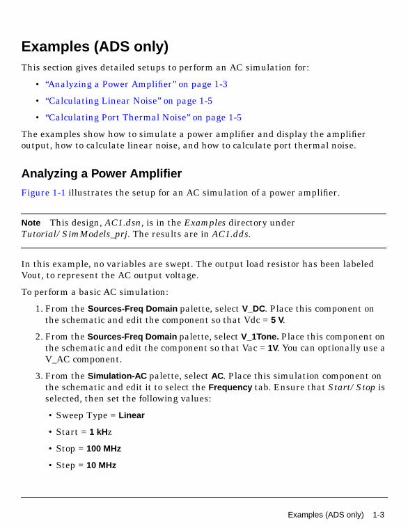
Figure 1-1 illustrates the setup for an AC simulation of a power amplifier.
Note This design, AC1.dsn, is in the Examples directory underTutorial/SimModels_prj. The results are in AC1.dds.
In this example, no variables are swept. The output load resistor has been labeledVout, to represent the AC output voltage.
To perform a basic AC simulation:
1. From the Sources-Freq Domain palette, select V_DC. Place this component onthe schematic and edit the component so that Vdc = 5 V.
2. From the Sources-Freq Domain palette, select V_1Tone. Place this component onthe schematic and edit the component so that Vac = 1V. You can optionally use aV_AC component.
3. From the Simulation-AC palette, select AC. Place this simulation component onthe schematic and edit it to select the Frequency tab. Ensure that Start/Stop isselected, then set the following values:
• Sweep Type = Linear
• Start = 1 kHz
• Stop = 100 MHz
• Step = 10 MHz
Examples (ADS only) 1-3

Linear AC and Noise Simulation
Figure 1-1. Example setup for a basic AC simulation
4. Click OK to accept changes and close the dialog box.
5. Simulate . When the simulation is finished, a Data Display window opens. PlotVout . The following illustration shows a plot of AC output voltage (Vout), in dB,versus frequency:
1-4 Examples (ADS only)

Calculating Linear Noise
You can simulate linear noise by setting the appropriate options via the Noise tab ofthe AC Simulation component.
To perform a linear noise analysis:
1. In the circuit to be simulated, ensure that you have named the nodes at whichnoise data are to be reported (for example, Input and Output).
2. Edit the AC Simulation component and select Noise , then select Calculate Noise .
3. In the Edit field, enter the names of nodes at which you want noise data to bereported.
4. Use the Mode popup menu to obtain the noise contributed by individual noisesources and sort these contributions by name or value. To obtain just the totalnoise value at the output only, set Mode to Off.
5. Either accept the default for Bandwidth, or edit it as required. The default isoften sufficient.
6. Enter a value in the Dynamic range to display field, in dB. The default is oftensufficient if Mode is set to On.
7. Click OK to accept changes and close the dialog box.
8. Launch the simulation. To display and plot resulting data, refer to the DataDisplay manual.
Calculating Port Thermal Noise
To simulate port thermal noise:
Proceed as in “Calculating Linear Noise” on page 1-5, with the following additionalsteps prior to launching the simulation:
• Ensure that you have placed input and output ports in the circuit.
• Select the Include port noise option
For information on how noise is calculated, refer to “Linear Noise SimulationDescription” on page 1-8.
Examples (ADS only) 1-5

Linear AC and Noise Simulation
AC Simulation DescriptionWhen an AC small-signal simulation is run, the system first computes the DCoperating point of the circuit. Whenever a linear simulation such as a linear ACsimulation requires a single-point DC bias simulation to be run first, it is referred toas a bias-dependent linear simulation. The most common example is the case of alinear amplifier that uses a biased transistor as the active element. The DC biassimulation is executed automatically and transparently (unless an error causes theDC simulation to fail to converge).
Following the DC bias simulation, the simulator linearizes all nonlinear devicesabout their bias points. A linearized model captures the small incremental changes ofcurrent due to small incremental changes of voltage. These are the derivatives of thetransistor model equations, which are evaluated at the DC bias point. Nonlinearresistors and current sources are replaced by linear resistors whose values are set bythe small signal conductance dI/dV. Current sources that depend on voltages otherthan the voltage across the source are replaced by linear dependent current sourcesdI1/dV2. Nonlinear capacitors are replaced by linear capacitors of value dQ/dV.
The resulting linear circuit is then simulated over the specified frequency range.Small-signal AC simulation is also performed before a harmonic-balance (spectral)simulation to generate an initial guess at the final solution.
Use the AC controller to:
• Perform a swept-frequency or swept-variable small-signal linear ACsimulation.
• Obtain small-signal transfer parameters, such as voltage gain, current gain,transimpedance, transadmittance, and linear noise.
Simulation can be performed repeatedly while sweeping some parameter. If changingthese parameters affects the DC operating point, the DC operating point andlinearized circuit will be recomputed at each step.
Note If the circuit has only one AC source, it is often convenient to set its magnitudeto one and its phase to zero. In this way, the small-signal transfer function iscomputed directly.
1-6 AC Simulation Description
Enabling Frequency Conversion
Traditional small-signal AC analysis is truly linear in the sense that frequencyconversion effects do not occur. In RF system simulation, however, it is common tohave frequency-translating mixer components that have approximately linearRF-to-IF conversion characteristics under small-signal RF drive. By enablingfrequency conversion (also known as FCAC), you can perform system-levelsmall-signal analyses on such systems. As is the case in standard AC analysis, anoise option is also available.
At the beginning of each FCAC simulation, a so-called frequency map is established.This map specifies the frequencies present at the various circuit nodes, and is basedon the frequencies of the sources and the types of behavioral mixer componentspresent in the network. Each node in the network can have only one frequencyassociated with it. Consequently, each behavioral mixer component can modelfrequency conversion to either the upper or the lower sideband, but not to bothsimultaneously.
Sources most often used for FCAC analysis include the V_1Tone, I_1Tone, andP_1Tone components. The frequency used by the source is given by the Freqparameter. If a multitone source is used, the frequency is specified by the Freq[1]parameter. When no frequency is explicitly specified, voltage and current sourcesdefault to the global value of the freq variable, while port sources simply becomepassive. Small-signal amplitudes used for FCAC analysis are given by Vac, Iac, andPac parameters for voltage sources, current source, and ports, respectively.
Note It is not possible to use FCAC analysis accurately with user-constructedcircuit-level mixer blocks (such as diode mixers, Gilbert cell mixers, and the like).
AC Simulation Description 1-7

Linear AC and Noise Simulation
Linear Noise Simulation DescriptionLinear noise simulation is an option available with the AC and S-parametersimulators. The frequency at which the noise is analyzed is the same as the ACsimulation frequency. Noise voltages and currents are saved in the dataset with thekeyword Noise included in the parameter name to identify the type of simulation.
The simulator performs an arbitrary-topology, multiport, network noise simulation.The following noise contributions are included in this simulation:
• Temperature-dependent thermal noise from lossy passive elements, includingthose specified by data files
• Temperature and bias-dependent noise from nonlinear devices
• Noise from linear active devices specified by 2-port data files that include noiseparameters
• Noise from noise source elements
The noise simulation computes the noise generated by each element, and thendetermines how that noise affects the noise properties of the network. In most cases,the noise generated by circuit elements is calculated automatically. Lossy passiveelements, for example, contribute noise according to their ability to deliver thermalnoise power. The noise contributions from nonlinear devices are computed by modelsthat include temperature and bias dependence; those models are similar to thoseused by SPICE. The computation of network-level noise properties from thecomponent elements is performed by means of noise-correlation matrices. Most noisemeasurements are based on either noise figure or noise parameter calculations, whichare defined for 2-port networks only. For networks with more than two ports, thenoise figure can be measured between two user-specified ports using Input Port andOutput Port; the other ports are treated as resistors for the noise simulation.
Note The temperature of lossy passive elements is used to calculate their noisecontributions. Since a lossy passive element at a physical temperature of 0 K does notgenerate any thermal noise, you may want to disable the noise contribution of anysuch element by setting its physical temperature to –273.15 degrees Celsius (0 K). Donot use this method for nonlinear devices such as transistors. Use the Noiseparameter for resistors and nonlinear devices to enable (Noise = YES) or disable(Noise = NO) noise generation.
1-8 Linear Noise Simulation Description
The program’s nonlinear device models include one or more of the following noiseeffects:
• Thermal noise generated by the resistances that exist within the nonlineardevice models. This noise is proportional to the device temperature and isindependent of bias.
• Channel noise for JFET, MESFET, HEMT and similar devices. This noise maybe due to thermal noise, high-field diffusion noise, or other effects. This noise isgenerally a function of device temperature and bias.
• Shot noise is caused by the quantized and random nature of current flow acrossjunctions and is modeled for diodes and BJTs. This noise is proportional to thedevice bias current and is independent of temperature.
• Flicker (1/f) noise is modeled in most nonlinear devices.
• Burst (or popcorn) noise is another low-frequency, bias-dependent noise effectmodeled in bipolar transistors.
Linear Noise Simulation Description 1-9
Linear AC and Noise Simulation
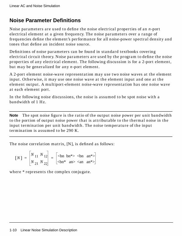
Noise Parameter Definitions
Noise parameters are used to define the noise electrical properties of an n-portelectrical element at a given frequency. The noise parameters over a range offrequencies define the element’s performance for all noise-power spectral density andtones that define an incident noise source.
Definitions of noise parameters can be found in standard textbooks coveringelectrical circuit theory. Noise parameters are used by the program to define the noiseproperties of any electrical element. The following discussion is for a 2-port element,but may be generalized for any n-port element.
A 2-port element noise-wave representation may use two noise waves at the elementinput. Otherwise, it may use one noise wave at the element input and one at theelement output. A multiport-element noise-wave representation has one noise waveat each element port.
In the following noise discussions, the noise is assumed to be spot noise with abandwidth of 1 Hz.
Note The spot noise figure is the ratio of the output noise power per unit bandwidthto the portion of output noise power that is attributable to the thermal noise in theinput termination per unit bandwidth. The noise temperature of the inputtermination is assumed to be 290 K.
The noise correlation matrix, [N], is defined as follows:
where * represents the complex conjugate.
N[ ]N11 N12
N21 N22
<bn bn*> <bn an*>
<bn* an> <an an*>= =
1-10 Linear Noise Simulation Description

Noise Entries in a Dataset
When an AC simulation runs with the linear noise simulation option enabled, noisevoltages and currents are saved in a dataset. The dataset includes the keyword Noisein the parameter name to identify the type of simulation. The entries in the datasetgenerated from an AC noise simulation include:
These entries can be viewed in the data display. For example, in a simple circuit withtwo noise generators, resistors R1 and R2, plotting name and vnc on a list, generatesthe following table:
These results show that R1 and R2 are each contributing an equal amount of noise tothe total. Notice that the sum of the individual contributors does not add up to thevalue for _total. The sum of the squares of the individual noise contributors is equalto the total noise voltage squared.
Note vout.noise reports that same noise voltage as the value of vnc associated withthe name _total.
vout.noise Total noise voltage at node Vout
vnc Noise contributors (noise voltage contribution from each noisegenerator in the circuit)
name Instance name of noise contributor
name vnc
_total 641.6 pV
R1 453.7 pV
R2 453.7 pV
Linear Noise Simulation Description 1-11
Linear AC and Noise Simulation
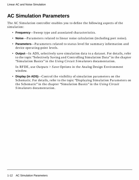
AC Simulation ParametersThe AC Simulation controller enables you to define the following aspects of thesimulation:
• Frequency —Sweep type and associated characteristics.
• Noise —Parameters related to linear noise calculation (including port noise).
• Parameters —Parameters related to status level for summary information anddevice operating-point levels.
• Output —In ADS, selectively save simulation data to a dataset. For details, referto the topic “Selectively Saving and Controlling Simulation Data” in the chapter“Simulation Basics” in the Using Circuit Simulators documentation.
In RFDE, use Outputs > Save Options in the Analog Design Environmentwindow.
• Display (in ADS) —Control the visibility of simulation parameters on theSchematic. For details, refer to the topic “Displaying Simulation Parameters onthe Schematic” in the chapter “Simulation Basics” in the Using CircuitSimulators documentation.
1-12 AC Simulation Parameters

Setting up a Sweep in ADS
Setting up the sweep portion of the simulation consists of two basic parts:
• Selecting the sweep type and setting the associated characteristics
• Optionally, specifying a sweep plan
To shorten simulation time in any parameter sweep, select a start point as close aspossible to the convergence point and vary the parameter gradually. This yieldsbetter estimates for the next simulation, and achieves convergence more rapidly thanif the parameter were changed abruptly. Names used in netlists and ADS schematicsappear under Parameter Name.
Table 1-1. ADS AC Simulation Sweep Options
Setup Dialog Name Parameter Name Description
Frequency
Sweep Type—The sweep type and parameters.
Single point () Freq Enables simulation at a single frequency point. Specify the desired value in theFrequency field.
Linear Enables sweeping a range of values based on a linear increment. ClickStart/Stop to set start and stop values for the sweep, or Center/Span to set thecenter value and a span of the sweep.
Log Enables sweeping a range of values based on a logarithmic increment. ClickStart/Stop to set start and stop values for the sweep, or Center/Span to set thecenter value and a span of the sweep.
Start/Stop
Start, Stop, Step-size,Pts./decade, Num. of pts.
StartStopStepDecLin
Select the Start/Stop option to sweep based on start, stop, step-size orpts./decade, and number of points. Linear sweep uses Step-size; Log sweepuses Pts./decade.- Start—the start point of a sweep- Stop—the stop point of a sweep- Step-size—the increments at which the sweep is conducted- Pts./decade—number of points per decade- Num. of pts.—the number of points over which sweep is conducted
Center/Span
Center, Span, Step-size,Pts./decade. Num. of pts.
CenterSpanStepDecLin
Select the Center/Span option to sweep based on center and span, step-size orpts./decade, and number of points. Linear sweep uses Step-size; Log sweepuses Pts./decade.- Center—the center point of a sweep- Span—the span of a sweep- Step-size—the increments at which the sweep is conducted- Pts./decade—number of points per decade- Num. of pts.—the number of points over which sweep is conducted
Note: Changes to any of the Start, Stop, etc. fields causes the remaining fields to be recalculated automatically.
Use sweep plan SweepPlan Enables use of an existing sweep plan component (SweepPlan). Select thisoption and enter the name of the plan or select it from the drop-down list.
AC Simulation Parameters 1-13

Linear AC and Noise Simulation
Setting up a Sweep in RFDE
Setting up the sweep portion of the simulation consists of two basic parts:
• Specifying the parameter type
• Specifying a sweep plan
To shorten simulation time in any parameter sweep, select a start point as close aspossible to the convergence point and vary the parameter gradually. This yieldsbetter estimates for the next simulation, and achieves convergence more rapidly thanif the parameter were changed abruptly.
Table 1-2. RFDE AC Simulation Parameter Sweep
Setup Dialog Name Parameter Name Description
Parameter Type
Frequency freq is automatically selected because it is a reserved variable name.
Design Variable Click Select to choose a variable name from the Select Design Variable form.The list contains variables set up in the Editing Design Variables form. You canalso type in a name in the Variable Name field. However, the variable must existin the design for a successful simulation. Also enter a value for At Frequency.
Temperature temp is automatically selected because it is a reserved variable name. Alsoenter a value for At Frequency.
Component Parameter Click Select and choose a component from the schematic. In the SelectComponent Parameter form, select the parameter to be swept, then click OK.You can also type in the names in the Component Name and Parameter Namefields. However, the component and parameter must exist in the design for asuccessful simulation. Also enter a value for At Frequency.
Model Parameter Type in the name of a defined model and the name of the model parameter to beswept. Also enter a value for At Frequency.
At Frequency The frequency at which to sweep the variable.
Sweep Plan
Choose one sweep range:
Start-Stop
Start, Stop
Sets the Start and Stop values of the sweep- Start - The start point of the sweep- Stop - The stop point of the sweep
Center-Span
Center, Span
Sets the Center value and a Span of the sweep.- Center - The center point of a sweep- Span - The span of a sweep
1-14 AC Simulation Parameters

Choose one sweep type:
Linear Enables sweeping a range of values based on a linear increment. Set theincrement with Step Size or Number of Steps. Use Additional Points to addspecific values.Step Size - The increments at which the sweep is conductedNumber of Steps - The number of points over which sweep is conducted
Logarithmic Enables sweeping a range of values based on a logarithmic increment. Set theincrement with Points Per Decade or Number of Steps. Use Additional Points toadd specific values.Points Per Decade - The number of points per decade.Number of Steps - The number of points over which sweep is conducted
Points Only Enables simulation at specific values for the parameter. Enter values in theSpecific Points field with a space between each one.
Additional Points When sweep type is Linear or Logarithmic, click this option to enter specificvalues to include in the sweep range. Enter values with a space between eachone.
Table 1-2. RFDE AC Simulation Parameter Sweep
Setup Dialog Name Parameter Name Description
AC Simulation Parameters 1-15
Linear AC and Noise Simulation
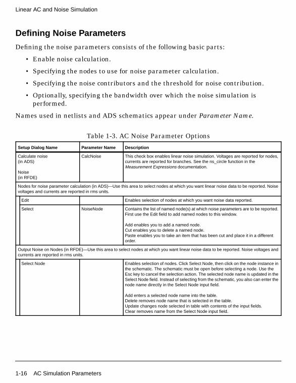
Defining Noise Parameters
Defining the noise parameters consists of the following basic parts:
• Enable noise calculation.
• Specifying the nodes to use for noise parameter calculation.
• Specifying the noise contributors and the threshold for noise contribution.
• Optionally, specifying the bandwidth over which the noise simulation isperformed.
Names used in netlists and ADS schematics appear under Parameter Name.
Table 1-3. AC Noise Parameter Options
Setup Dialog Name Parameter Name Description
Calculate noise(in ADS)
Noise(in RFDE)
CalcNoise This check box enables linear noise simulation. Voltages are reported for nodes,currents are reported for branches. See the ns_circle function in theMeasurement Expressions documentation.
Nodes for noise parameter calculation (in ADS)—Use this area to select nodes at which you want linear noise data to be reported. Noisevoltages and currents are reported in rms units.
Edit Enables selection of nodes at which you want noise data reported.
Select NoiseNode Contains the list of named node(s) at which noise parameters are to be reported.First use the Edit field to add named nodes to this window.
Add enables you to add a named node.Cut enables you to delete a named node.Paste enables you to take an item that has been cut and place it in a differentorder.
Output Noise on Nodes (in RFDE)—Use this area to select nodes at which you want linear noise data to be reported. Noise voltages andcurrents are reported in rms units.
Select Node Enables selection of nodes. Click Select Node, then click on the node instance inthe schematic. The schematic must be open before selecting a node. Use theEsc key to cancel the selection action. The selected node name is updated in theSelect Node field. Instead of selecting from the schematic, you also can enter thenode name directly in the Select Node input field.
Add enters a selected node name into the table.Delete removes node name that is selected in the table.Update changes node selected in table with contents of the input fields.Clear removes name from the Select Node input field.
1-16 AC Simulation Parameters
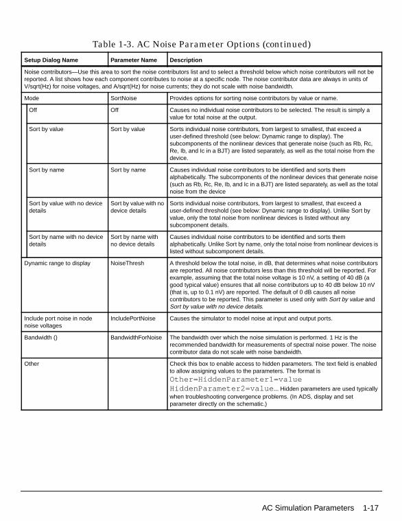
Noise contributors—Use this area to sort the noise contributors list and to select a threshold below which noise contributors will not bereported. A list shows how each component contributes to noise at a specific node. The noise contributor data are always in units ofV/sqrt(Hz) for noise voltages, and A/sqrt(Hz) for noise currents; they do not scale with noise bandwidth.
Mode SortNoise Provides options for sorting noise contributors by value or name.
Off Off Causes no individual noise contributors to be selected. The result is simply avalue for total noise at the output.
Sort by value Sort by value Sorts individual noise contributors, from largest to smallest, that exceed auser-defined threshold (see below: Dynamic range to display). Thesubcomponents of the nonlinear devices that generate noise (such as Rb, Rc,Re, Ib, and Ic in a BJT) are listed separately, as well as the total noise from thedevice.
Sort by name Sort by name Causes individual noise contributors to be identified and sorts themalphabetically. The subcomponents of the nonlinear devices that generate noise(such as Rb, Rc, Re, Ib, and Ic in a BJT) are listed separately, as well as the totalnoise from the device
Sort by value with no devicedetails
Sort by value with nodevice details
Sorts individual noise contributors, from largest to smallest, that exceed auser-defined threshold (see below: Dynamic range to display). Unlike Sort byvalue, only the total noise from nonlinear devices is listed without anysubcomponent details.
Sort by name with no devicedetails
Sort by name withno device details
Causes individual noise contributors to be identified and sorts themalphabetically. Unlike Sort by name, only the total noise from nonlinear devices islisted without subcomponent details.
Dynamic range to display NoiseThresh A threshold below the total noise, in dB, that determines what noise contributorsare reported. All noise contributors less than this threshold will be reported. Forexample, assuming that the total noise voltage is 10 nV, a setting of 40 dB (agood typical value) ensures that all noise contributors up to 40 dB below 10 nV(that is, up to 0.1 nV) are reported. The default of 0 dB causes all noisecontributors to be reported. This parameter is used only with Sort by value andSort by value with no device details.
Include port noise in nodenoise voltages
IncludePortNoise Causes the simulator to model noise at input and output ports.
Bandwidth () BandwidthForNoise The bandwidth over which the noise simulation is performed. 1 Hz is therecommended bandwidth for measurements of spectral noise power. The noisecontributor data do not scale with noise bandwidth.
Other Check this box to enable access to hidden parameters. The text field is enabledto allow assigning values to the parameters. The format isOther=HiddenParameter1=valueHiddenParameter2=value ... Hidden parameters are used typicallywhen troubleshooting convergence problems. (In ADS, display and setparameter directly on the schematic.)
Table 1-3. AC Noise Parameter Options (continued)
Setup Dialog Name Parameter Name Description
AC Simulation Parameters 1-17

Linear AC and Noise Simulation
Defining Simulation Parameters
Defining the simulation parameters consists of the following basic parts:
• Enabling the frequency conversion (in ADS).
• Enabling the budget simulation (in ADS).
• Specifying the desired level of detail in the simulation status summary.
• Specifying the amount of device operating-point information to save.
Names used in netlists and ADS schematics appear under Parameter Name.
Table 1-4. AC Simulation Parameter Options
Setup Dialog Name Parameter Name Description
Frequency Conversion (ADS only)
Enable AC frequencyconversion
FreqConversion Causes a frequency-converting AC analysis to be performed.
Budget (ADS only)
Perform Budget simulation OutputBudgetIV Enables Budget simulation, which reports current and voltage data at the pins ofdevices following a simulation. Current into the nth terminal of a device isidentified as ...device_name.tn.i. Voltage at the nth terminal of a device isidentified as ...device_name.tn.v.
Levels (in ADS)
Annotation (in RFDE)
Enables you to set the level of detail in the simulation status report.
Status level StatusLevel Prints information about the simulation in the Status/Summary part of theMessage Window.- 0 reports little or no information, depending on the simulation engine.- 1 and 2 yield more detail.- Use 3 and 4 sparingly since they increase process size and simulation timesconsiderably.
The type of information printed may include the sum of the current errors at eachcircuit node, whether convergence is achieved, resource usage, and where thedataset is saved. The amount and type of information depends on the statuslevel value and the type of simulation.
Device operating point level DevOpPtLevel Options to save device operating-point information for most active devices andsome linear devices in the circuit to the dataset. In ADS, if this simulationperforms more than one AC analysis (from multiple AC controllers), the deviceoperating point data for all AC analyses will be saved, not just the last one.Default setting is None
None None No information is saved.
Brief Brief Saves device currents, power, and some linearized device parameters.
Detailed Detailed Saves the operating point values which include the device’s currents, power,voltages, and linearized device parameters.
1-18 AC Simulation Parameters
Index
Aac frequency conversion, 1-7ac simulationand linear noise, 1-8AC Simulation component, 1-1ac simulations, 1-1
about, 1-6and dc simulations, 1-6and harmonic balance simulations, 1-6and noise, 1-5for power amplifier analysis, 1-3performing, 1-2simulation parameters, 1-12
Bbudget simulations
and harmonic balance simulations, 1-18
FFCAC (frequency-converting AC), 1-7frequency conversion, 1-7, 1-18
effects on ac linear noise, 1-7
Hharmonic balance simulations
and budget simulations, 1-18
Llinear noise
and ac simulation, 1-8calculating, 1-5
Nnoise
dataset entries, 1-11linear, calculating, 1-5noise parameter definitions, 1-10port thermal, 1-5
noise parameters, 1-7
Pport thermal noise, 1-5
Ssimulation parameters
ac simulation, 1-12
small-signal transfer parameters, 1-1
Index-1

Index-2