Embed Size (px)
Citation preview

Art.No.: AC-DOC_SY-KIT-Lambda-addon_08-000 modified 14.05.2009
t3:52.5 3:55.0 3:57.5 4:00.0 4:02.5 4:05.0 4:07.5 4:10.0
rpm
025
0050
0075
0010
000
1250
0%
025
5075
100
km/h
025
5075
100
125
150
175
200
225
1:42
.60
Start
AC-DOC_SY-KIT-Lambda-addon_08-000 page 2 / 8
Table of content
Table of content ......................................................................................................................................................... 2Preface ...................................................................................................................................................................... 3
SYMBOLS USED IN THE TEXT ...................................................................................................................31. Basic information of all modules and their features ............................................................................................... 42. The Linear A/F (lambda) add-on kit ....................................................................................................................... 5
2.1 MOUNTING THE A/F UNIT..................................................................................................................52.2 MOUNTING THE A/F (LAMBDA) SENSOR .............................................................................................62.3 CONNECTING THE A/F (LAMBDA) UNIT ...............................................................................................7
AC-DOC_SY-KIT-Lambda-addon_08-000 page 3 / 8
Preface
This documentation contains the necessary information to setup and to work with the 2D kit system.
In order to achieve the optimum result when working with the 2D-Kit System, we recommend to readthe instructions carefully and follow them step by step.
Symbols used in the text
In the paragraphs highlighted with this symbol, you will find tips and practical advice towork with the 2D-Kit System.
In the paragraphs highlighted with this symbol, you will find additional information and it isvery important that you follow the instructions given.
Documentation referenceð The user get an unique item number for an user manual to find further assistance
Additional information about manuals, datasheets, software updates or new calculationfiles can be downloaded from our homepage. The specific download area for the Kitsystem can be found at: http://www.2d-kit-system.com (=>See Downloads)
Basic Kit
Sensor options
A/F (lambda) add-on Kit (4-stroke) with 1CH or 2CH
Deto add-on Kit (2-stroke)
Possible Updates
Kit software user manual (delivered with the CD: SW-CD RaceKIT)
2D Debus & DieboldMeßsysteme GmbHAlte Karlsruher Straße 876227 KarlsruheTel.: +49(0)721 94485-0Fax: +49(0)721 94485-29EMAIL: [email protected]: http://www.2D-Datarecording.comHomepage: http://www.2D-Kit-System.com

AC-DOC_SY-KIT-Lambda-addon_08-000 page 4 / 8
1. Basic information of all modules and their features
SY-KITLSU_01-08-000: Linear A/F lambda (1 channel) add-on kit:The 1 Channel Lambda extension kit simplifies enginesetup by direct linear measurement of the lambda (A/F)value of 1 cylinder at any condition. Measures Lambdavalue with a high quality linear Bosch LSU 4.2 sensor. TheAmplifier uses full controlled heating for temperaturestabilization. Also heater off with engine off is implementedto save electrical power. The Unit is derivated from the 4Channel controller which is used in MotoGP.
Can also be used as standalone unit for bench test
SY-KITLSU_02-08-000: Linear A/F lambda (2 channel) add-on kitThis system is analog to the 1 channel LSU. Instead of 1channel Lambda you have 2 channels.
AC-DOC_SY-KIT-Lambda-addon_08-000 page 5 / 8
2. The Linear A/F (lambda) add-on kit
The kit consists of an Air/Fuel (lambda) controller unit and the A/F (lambda) sensor.
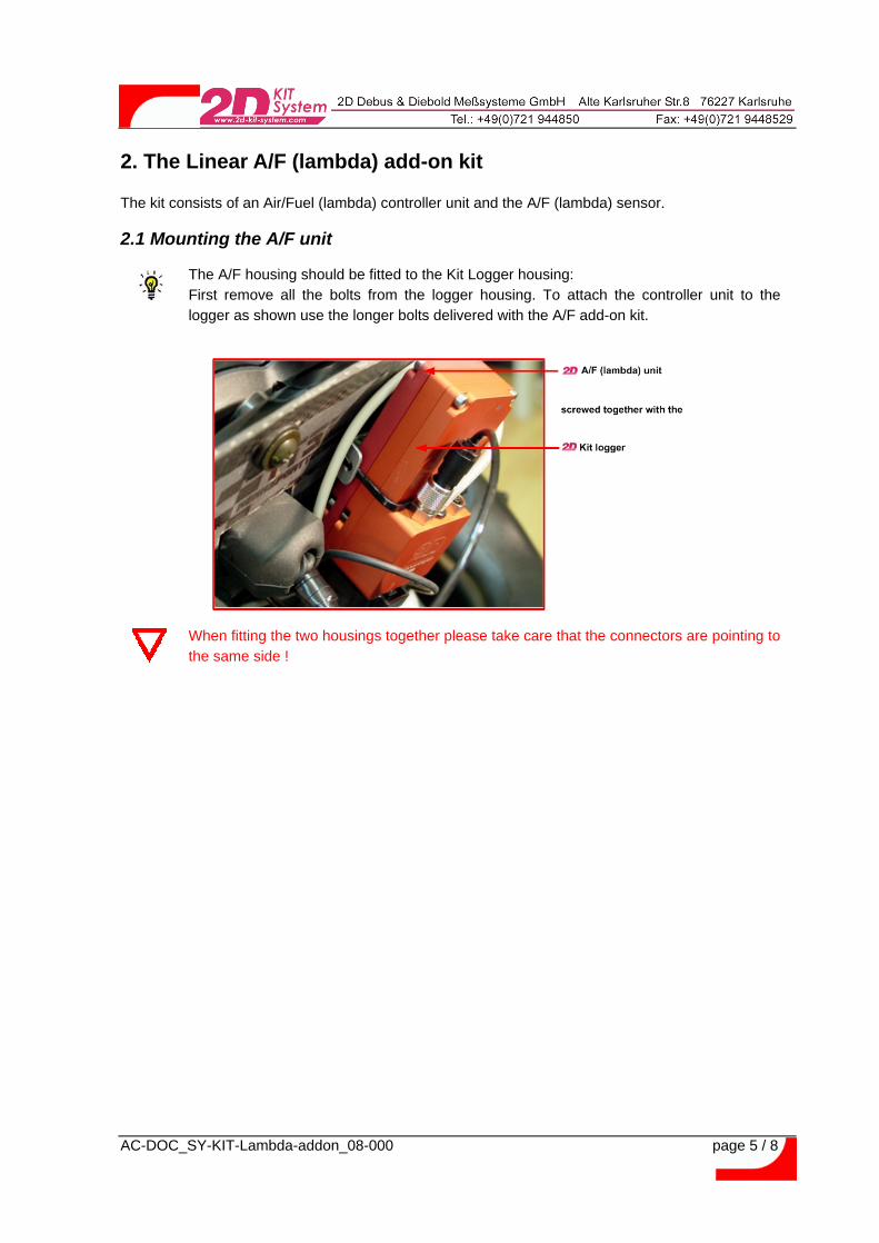
2.1 Mounting the A/F unit
The A/F housing should be fitted to the Kit Logger housing:First remove all the bolts from the logger housing. To attach the controller unit to thelogger as shown use the longer bolts delivered with the A/F add-on kit.
When fitting the two housings together please take care that the connectors are pointing tothe same side !

AC-DOC_SY-KIT-Lambda-addon_08-000 page 6 / 8
2.2 Mounting the A/F (lambda) sensor
The A/F (lambda) sensor should be installed onto the exhaust collector close to the join ofthe four collector pipes (in the case of a 4-in-1 system)
Many exhaust systems provide already a thread to attach a lambda sensor. In order to fit the A/F(lambda) sensor determine first the exact position of the A/F sensor.
Ensure carefully that the swing arm, the linkages, the fairing or other parts will not interferewith the sensor or the cable at any position. If possible the sensor should not be mountedwith it’s thread at the lowest position to avoid damage from condensing water !
The best way to fix the A/F sensor at the selected point to the exhaust collector is to fit a screw collar(or nut) soldering it onto the exhaust collector. This screw-collar must guarantee an exact, stable andgas-seal fitting for the A/F sensor. The A/F sensor tip should reach about 15mm into the gas flow togive correct values.
Once you have fixed the screw collar a hole has to be drilled into the exhaust collector (diametershould be inner screw collar diameter) and then drilling should be cleared using a tap with the samethread as the sensor. You can also drill the hole first and then solder the collar in-line onto the pipemaintaining the correct angle for the sensor.
If you are not very experienced with soldering exhaust parts we strongly recommend topass the part of the assembly process to a workshop with competence (and goodhistorical) for that type of modifications. Failing to solder the adapter correctly may crackthe sensor in the moment of fixing. It has to enter softly.Incorrect modifications can also damage the exhaust !

AC-DOC_SY-KIT-Lambda-addon_08-000 page 7 / 8
2.3 Connecting the A/F (lambda) unit
The wires of the A/F (lambda) unit are delivered from 2D with the “Tyco contact pins” alreadycrimped. Just insert the individual contacts into the 34pin AMP connector. The following tablegives you the correct positions for the pins.
Technical information Interface unit (34pin AMP connector)Cable length: 1000mmCrimp contacts: “Tyco crimp contacts”CAN_H (white) Pin 32 >> see appendixCAN_L (green) Pin 33 >> see appendixVext (red) Pin 34 >> see appendixBGND (black) Pin 25 >> see appendix

AC-DOC_SY-KIT-Lambda-addon_08-000 page 8 / 8
Required for:SY-KITLSU_01-08-000: Linear A/F lambda (1 channel) add-on kitSY-KITLSU_02-08-000: Linear A/F lambda (2 channel) add-on kit