Embed Size (px)
Citation preview
AC Coupled Diode DiscoveryTechnical Feasibility
IEEE802.3af Interim MeetingSeptember 2000
Rick Brooks, [email protected] Miller, [email protected]
Acknowledgments:Paul Moore, Geoff Thompson, Tom Gilheany, Richard Patchet,
Robert Muir, Kevin Brown, Dan Dove, Roger Karam, Avinom Levy,Nick Stapleton, Mike McCormack, Steve Ellsworth
P802.3af, Sept 2000 AC Coupled Diode Discovery Technical Feasibility Rick Brooks page 2 of 72
Contents:
• Coupled Diode Discovery Evaluation Board Update
• Discovery Process Update, the two stage approach
• Diode Loop Current Measurements
• Cable Transmission Mode Terminology: new term “ Pair to Pair” mode
• Discovery Pulse Spectrum
• EMC Test Results
• Common Mode Noise Rejection, Inhibited Discovery
• Cat-3 Cable Testing
• Crosstalk: Two Simultaneous Discovery Processes on a single CAT-5
• Discovery Process Impact on Data Integrity
• Hazard Matrix Testing, False Discovery
• Implementation Notes
• Future Tests
• Conclusions
• Reference Documents
P802.3af, Sept 2000 AC Coupled Diode Discovery Technical Feasibility Rick Brooks page 3 of 72
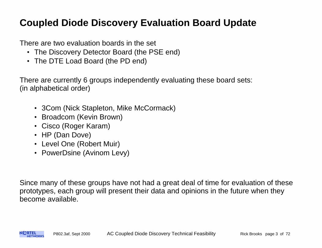
Coupled Diode Discovery Evaluation Board Update
There are two evaluation boards in the set• The Discovery Detector Board (the PSE end)• The DTE Load Board (the PD end)
There are currently 6 groups independently evaluating these board sets:(in alphabetical order)
• 3Com (Nick Stapleton, Mike McCormack)• Broadcom (Kevin Brown)• Cisco (Roger Karam)• HP (Dan Dove)• Level One (Robert Muir)• PowerDsine (Avinom Levy)
Since many of these groups have not had a great deal of time for evaluation of theseprototypes, each group will present their data and opinions in the future when theybecome available.

P802.3af, Sept 2000 AC Coupled Diode Discovery Technical Feasibility Rick Brooks page 4 of 72
DTE Detector Evaluation Board
magnetics(T1)
DC/DC power modulefor environment B
(mounted underneath)
PLD downloadconnector
PLD
power input connector,P2, pin 1
RJ-45 with power
RJ-45to legacy switch
Enable Jumper
C3348VDC
plus output48VDC
minus output
LED's
Detector Board Layout
P802.3af, Sept 2000 AC Coupled Diode Discovery Technical Feasibility Rick Brooks page 5 of 72
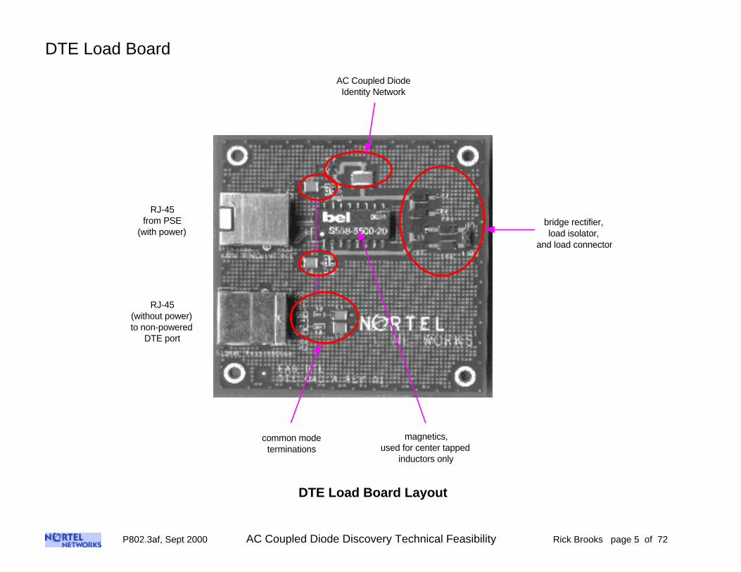
DTE Load Board
AC Coupled DiodeIdentity Network
bridge rectifier,load isolator,
and load connector
common modeterminations
RJ-45(without power)to non-powered
DTE port
RJ-45from PSE
(with power)
magnetics,used for center tapped
inductors only
DTE Load Board Layout

P802.3af, Sept 2000 AC Coupled Diode Discovery Technical Feasibility Rick Brooks page 6 of 72
DiodeT/R
Switch
POWER SOURCING EQUIPMENT POWERED DEVICE
POWERSUPPLY
DiscoveryProcess
PowerDeliveryProcess
DATACABLE
DiodeT/R
Switch
100 Ohm 100 Ohm
Comparator Comparator
LoopCurrent
Test Point
Load
AC coupleddiode
network
100k
2k
0.3 to 1uF
Diode Discovery Evaluation BoardsBlock Diagram
This shows the major components of the system• The PSE end, with the discovery and power processes• The discovery transmit/receive test point used for spectrum analysis below• The PD with the AC coupled diode identity network, and the load isolator (diodes)

P802.3af, Sept 2000 AC Coupled Diode Discovery Technical Feasibility Rick Brooks page 7 of 72
AC Coupled DiodeDiscovery Process Update
A new two stage approach
P802.3af, Sept 2000 AC Coupled Diode Discovery Technical Feasibility Rick Brooks page 8 of 72
Discovery Process Update, the two stage approach
We have been talking about the fact that for low duty cycle pulses, the AC coupleddiode network behaves essentially like a simple diode. But, when exited by a high dutycycle stream of pulses, it can be made to look like an open circuit. The current VerilogPLD code that is now implemented into the evaluation detector board uses this “ twostage” approach. Only after the successful completion of both stages can the DTEpower be energized.
• Discovery Stage 1:This is the same as described before. Currently, 256 consecutive successful discovery frames are required forcompletion. As before, the duty cycle is rather low, and the idle spaces are each an independent pseudo randomlength of time greater than 40 us. Also, as before, either polarity of the diode characteristic is accepted, toaccommodate both straight and crossover cables.
• Discovery Stage 2:Once stage one is completed, the same state machines used to form the discovery pulses start to use a muchshorter pseudo random idle time between pulses. The average duty cycle is set to be high enough to charge thediode coupling cap in the identity network. Now the diode characteristic disappears, and the identity networkbehaves like an open circuit. The requirement here is that 16 consecutive opens be detected in a maximum of64 discovery frames. When stage 2 is not successful, the discovery process must start at the beginning.
The benefit of this two stage approach is that legacy and unknown RJ-45 devices thatcontain a simple diode are now excluded from receiving power, and the overalllikelihood of a false discovery is reduced. One example of these types of devices arethose that contain a reversed biased diode as input protection on a power supply input.
P802.3af, Sept 2000 AC Coupled Diode Discovery Technical Feasibility Rick Brooks page 9 of 72
Two Stage Discovery Process: Discovery with “ Distortion”
The data:The waveforms shown below are for 260 meter CAT-5, and 2 meter CAT-5 cables, asnoted.Note that for the 260 meter cable, 17 2nd stage (distorted) discovery frames areneeded. Whereas, for the 2 meter cable, 28 2nd stage (distorted) discovery frames areneeded.This difference is purely the result of signal strength versus cable length
One limitation was noted on one particular detector board at very long cable lengths:On the unit that I tested, for CAT-5 cables between the lengths of 260 meters and 290meters, both the AC coupled diode and a normal diode loads were detected.
Above 290 meters, neither the AC coupled diode, nor the normal diode are detected.
Below 260 meters, only the AC coupled diode is detected.
Conclusion:Cables lengths like these are probably very unlikely, and would not support datacommunication anyway.
P802.3af, Sept 2000 AC Coupled Diode Discovery Technical Feasibility Rick Brooks page 10 of 72
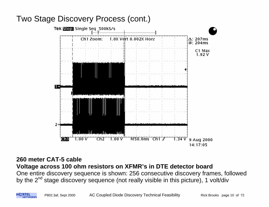
Two Stage Discovery Process (cont.)
260 meter CAT-5 cableVoltage across 100 ohm resistors on XFMR’s in DTE detector boardOne entire discovery sequence is shown: 256 consecutive discovery frames, followedby the 2nd stage discovery sequence (not really visible in this picture), 1 volt/div
P802.3af, Sept 2000 AC Coupled Diode Discovery Technical Feasibility Rick Brooks page 11 of 72
Two Stage Discovery Process (cont.)
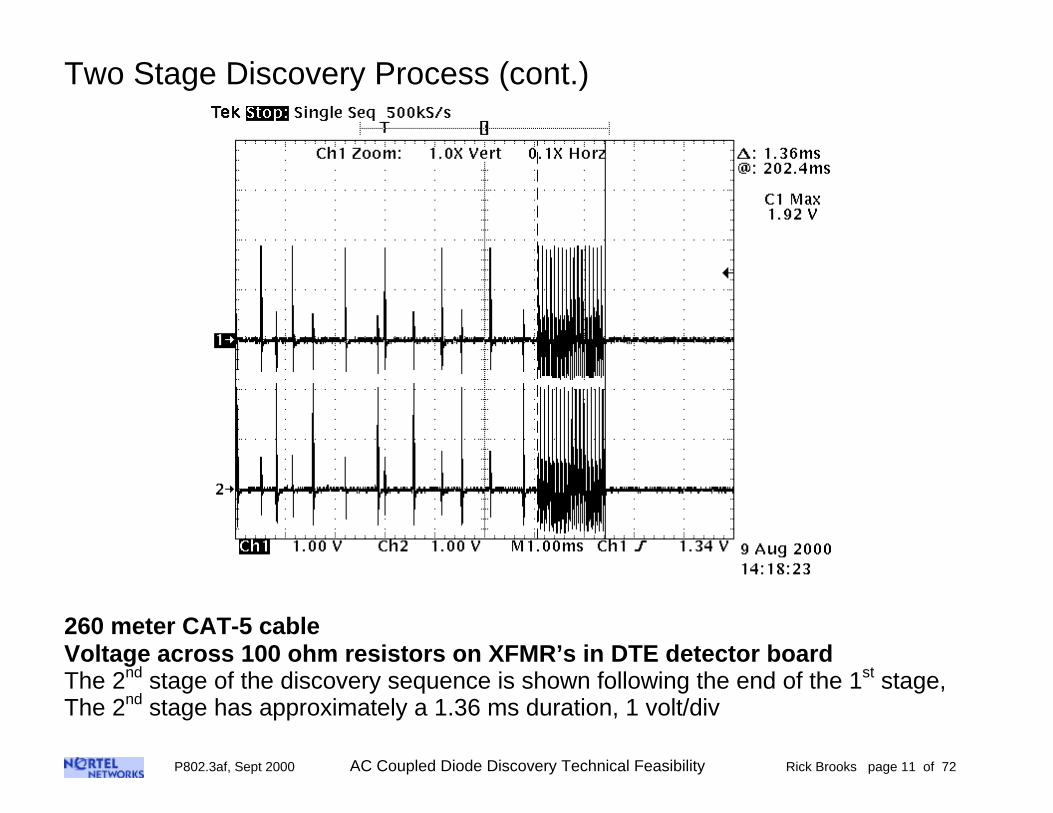
260 meter CAT-5 cableVoltage across 100 ohm resistors on XFMR’s in DTE detector boardThe 2nd stage of the discovery sequence is shown following the end of the 1st stage,The 2nd stage has approximately a 1.36 ms duration, 1 volt/div
P802.3af, Sept 2000 AC Coupled Diode Discovery Technical Feasibility Rick Brooks page 12 of 72
Two Stage Discovery Process (cont.)
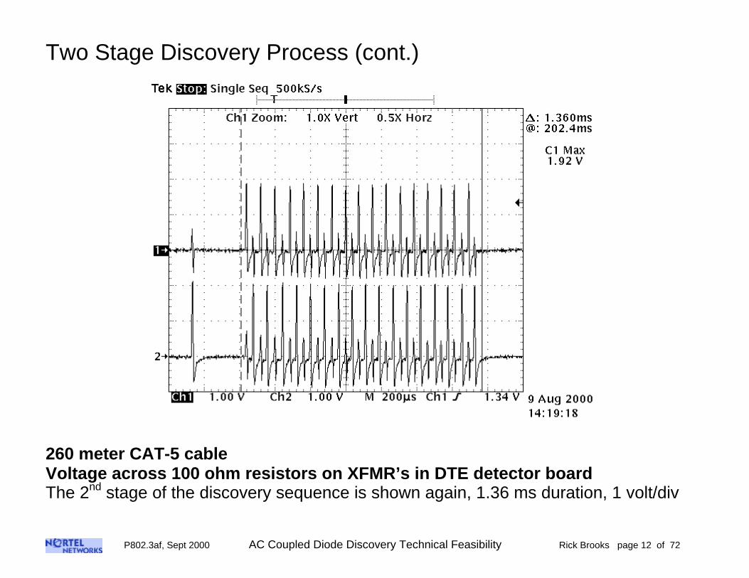
260 meter CAT-5 cableVoltage across 100 ohm resistors on XFMR’s in DTE detector boardThe 2nd stage of the discovery sequence is shown again, 1.36 ms duration, 1 volt/div
P802.3af, Sept 2000 AC Coupled Diode Discovery Technical Feasibility Rick Brooks page 13 of 72
Two Stage Discovery Process (cont.)
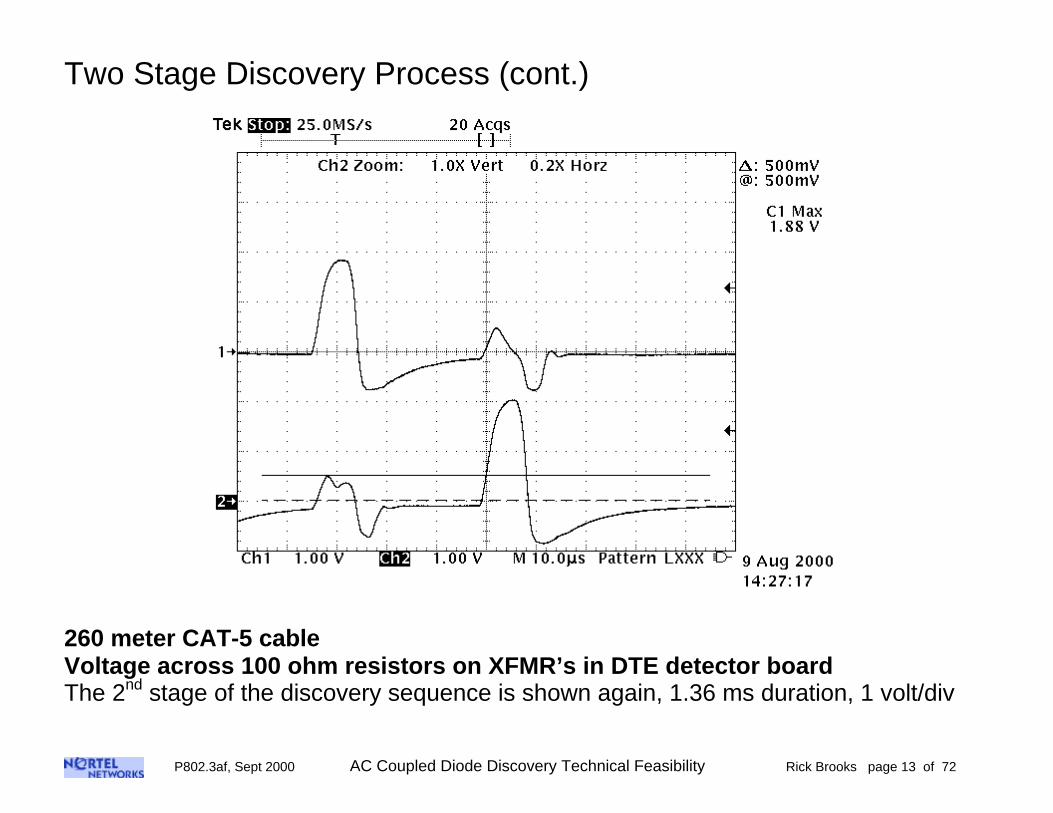
260 meter CAT-5 cableVoltage across 100 ohm resistors on XFMR’s in DTE detector boardThe 2nd stage of the discovery sequence is shown again, 1.36 ms duration, 1 volt/div

P802.3af, Sept 2000 AC Coupled Diode Discovery Technical Feasibility Rick Brooks page 14 of 72
Two Stage Discovery Process (cont.)
260 meter CAT-5 cableVoltage across 1 µF coupling capacitor in DTE load board, 200 mV/divOne entire discovery sequence is shown: 1st stage, and 2nd stageThe voltage rise at the end of the sequence is due to 2nd stage: the distortion sequence

P802.3af, Sept 2000 AC Coupled Diode Discovery Technical Feasibility Rick Brooks page 15 of 72
Two Stage Discovery Process (cont.)
260 meter CAT-5 cableVoltage across 1 µF coupling capacitor in DTE load board, 200 mV/divThe start of the discovery sequence, 1st stage, is shownNote the pseudo random ramp times
P802.3af, Sept 2000 AC Coupled Diode Discovery Technical Feasibility Rick Brooks page 16 of 72
Two Stage Discovery Process (cont.)
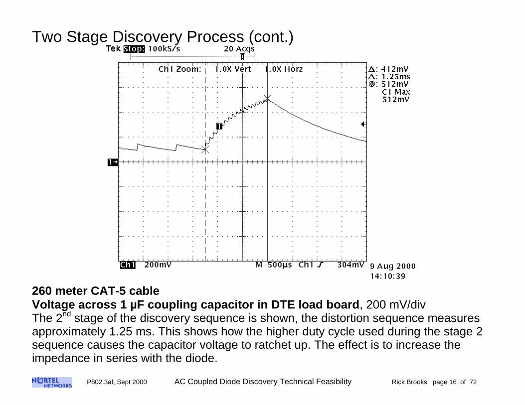
260 meter CAT-5 cableVoltage across 1 µF coupling capacitor in DTE load board, 200 mV/divThe 2nd stage of the discovery sequence is shown, the distortion sequence measuresapproximately 1.25 ms. This shows how the higher duty cycle used during the stage 2sequence causes the capacitor voltage to ratchet up. The effect is to increase theimpedance in series with the diode.
P802.3af, Sept 2000 AC Coupled Diode Discovery Technical Feasibility Rick Brooks page 17 of 72
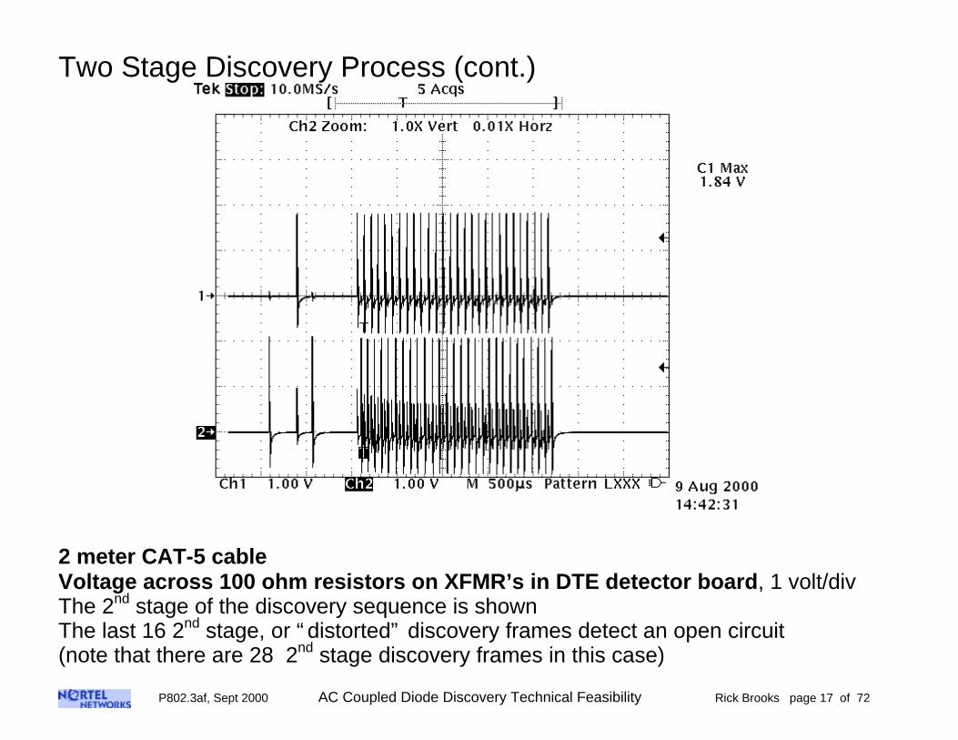
Two Stage Discovery Process (cont.)
2 meter CAT-5 cableVoltage across 100 ohm resistors on XFMR’s in DTE detector board, 1 volt/divThe 2nd stage of the discovery sequence is shownThe last 16 2nd stage, or “ distorted” discovery frames detect an open circuit(note that there are 28 2nd stage discovery frames in this case)
P802.3af, Sept 2000 AC Coupled Diode Discovery Technical Feasibility Rick Brooks page 18 of 72
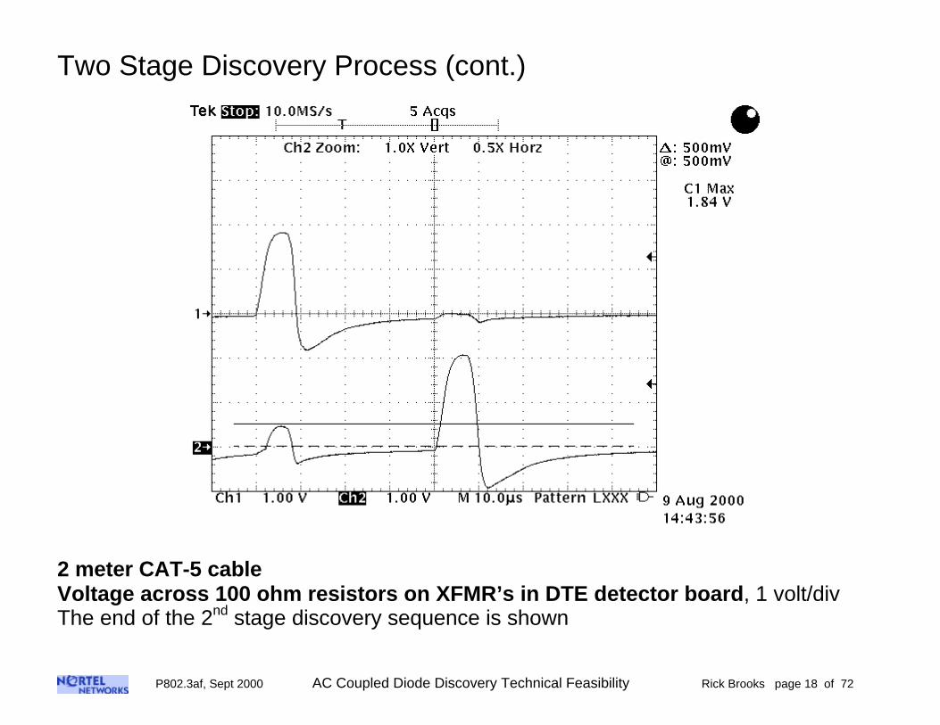
Two Stage Discovery Process (cont.)
2 meter CAT-5 cableVoltage across 100 ohm resistors on XFMR’s in DTE detector board, 1 volt/divThe end of the 2nd stage discovery sequence is shown

P802.3af, Sept 2000 AC Coupled Diode Discovery Technical Feasibility Rick Brooks page 19 of 72
Discovery Loop Current Waveforms

P802.3af, Sept 2000 AC Coupled Diode Discovery Technical Feasibility Rick Brooks page 20 of 72
AC Coupled Diode Discovery Loop Current TestCoupled Diode Identity Network Current Waveforms have been measured using the testsetup shown below. In order to get enough resolution on the scope, 10 turns werewound through the Tek current probe. Then the sensitivity was set on the probeamplifier to be 50mV per div. The net result is that the waveforms have a verticalresolution of 5 mV per Div.The peak current through the identity diode is about 12.5 ma for short UTP cables, andjust above 10 ma for the 145 meter cable.
Measurement SetupDiode Loop CurrentPair to Pair Mode
AC Coupled DiodeDTE Detector
Board
RJ-45
CAT-5cable
12
3
45
6
78
12
3
45
6
78
AC Coupled DiodeDTE Load
Board
12
3
45
6
78
12
3
45
6
78
TekCurrent
Probe Amp
10 Turns
Current Probe
Set at 50 ma per Div
Scope50 Ohm
Discovery Pulse Loop Current Test Setup
P802.3af, Sept 2000 AC Coupled Diode Discovery Technical Feasibility Rick Brooks page 21 of 72
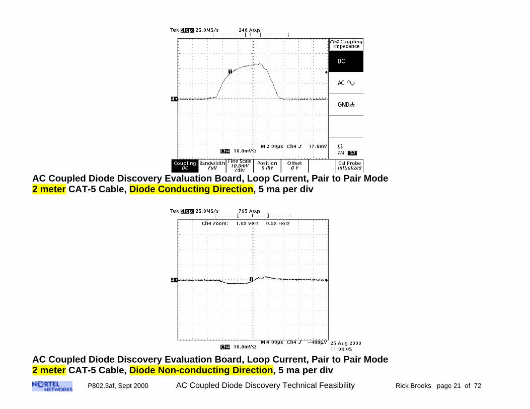
AC Coupled Diode Discovery Evaluation Board, Loop Current, Pair to Pair Mode2 meter CAT-5 Cable, Diode Conducting Direction, 5 ma per div
AC Coupled Diode Discovery Evaluation Board, Loop Current, Pair to Pair Mode2 meter CAT-5 Cable, Diode Non-conducting Direction, 5 ma per div
P802.3af, Sept 2000 AC Coupled Diode Discovery Technical Feasibility Rick Brooks page 22 of 72
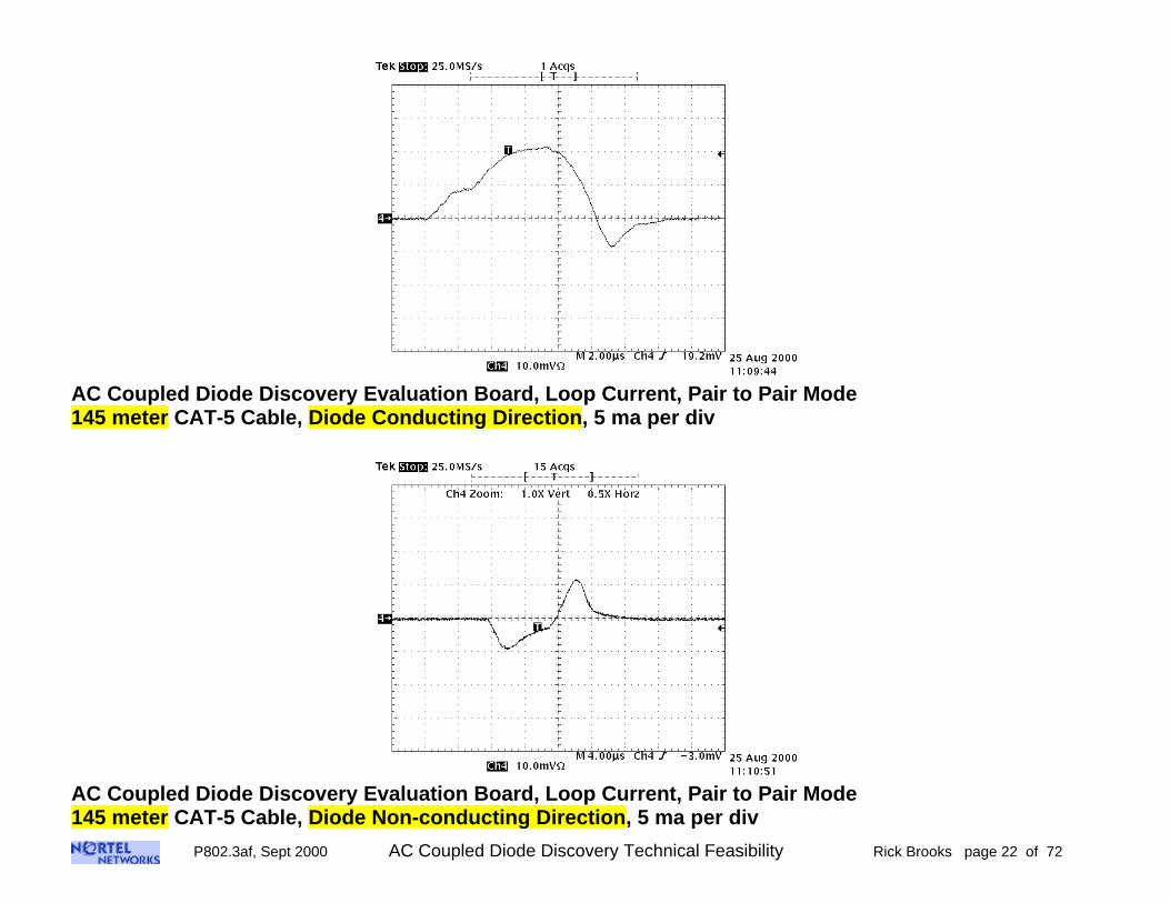
AC Coupled Diode Discovery Evaluation Board, Loop Current, Pair to Pair Mode145 meter CAT-5 Cable, Diode Conducting Direction, 5 ma per div
AC Coupled Diode Discovery Evaluation Board, Loop Current, Pair to Pair Mode145 meter CAT-5 Cable, Diode Non-conducting Direction, 5 ma per div

P802.3af, Sept 2000 AC Coupled Diode Discovery Technical Feasibility Rick Brooks page 23 of 72
UTP Cable Propagation Mode
P802.3af, Sept 2000 AC Coupled Diode Discovery Technical Feasibility Rick Brooks page 24 of 72
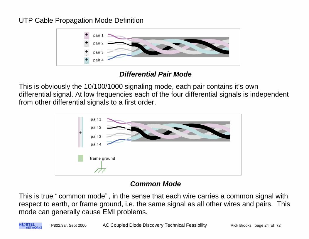
UTP Cable Propagation Mode Definition
+-
+-+-
+-
pair 1
pair 2
pair 3
pair 4
Differential Pair Mode
This is obviously the 10/100/1000 signaling mode, each pair contains it’s owndifferential signal. At low frequencies each of the four differential signals is independentfrom other differential signals to a first order.
-
+
pair 1
pair 2
pair 3
pair 4
frame ground
Common Mode
This is true “ common mode” , in the sense that each wire carries a common signal withrespect to earth, or frame ground, i.e. the same signal as all other wires and pairs. Thismode can generally cause EMI problems.

P802.3af, Sept 2000 AC Coupled Diode Discovery Technical Feasibility Rick Brooks page 25 of 72
UTP Cable Propagation Mode Definition
+-
pair 1
pair 2
pair 3
pair 4
-
+
-
+
Pair to Pair Mode
“ Pair to Pair” mode is the mode that IEEE802.3af has chosen for DTE power anddiscovery, one pair carries the DC send current, and another pair carries the DC returncurrent.
This mode has been referred to in the IEEE802.3af working group as “ common mode” ,but that is not really correct. Actual common mode is with respect to earth ground.However, what is true for the pair to pair mode, that each wire in a given pair carries acommon signal.
There are 6 examples of this mode: (pair-pair) 1-2, 1-3, 1-4, 2-3, 2-4, and 3-4.The four pair sets are all twisted around each other in CAT-3, CAT-5, etc… in a waythat is not necessarily well controlled.However, based on my measurements, all four pairs are coupled to each other, aswould be expected from the cable construction.

P802.3af, Sept 2000 AC Coupled Diode Discovery Technical Feasibility Rick Brooks page 26 of 72
AC Coupled Diode Discovery Spectrum

P802.3af, Sept 2000 AC Coupled Diode Discovery Technical Feasibility Rick Brooks page 27 of 72
AC Coupled Diode Discovery Spectrum
CommonMode Test
Fixture
32 dBGain
Preamp
SpectrumAnalyzer
with preampcompensation
RJ-45 portunder test
Test Setup
Common Mode Voltage on PSE Detector Board RJ-45 pins 4 and 5 (top trace)Noise Floor (bottom trace)Measured with a common mode test fixture for the RJ-45, as shown above, theSpectrum Analyzer had a 7 dB compensation for the preamp and fixture.The line at 65 dBuV represents a marker for radiated emissions above 30 MHzThe reference line at the top of the graph is 90 dBuV
P802.3af, Sept 2000 AC Coupled Diode Discovery Technical Feasibility Rick Brooks page 28 of 72
AC Coupled Diode Discovery Spectrum
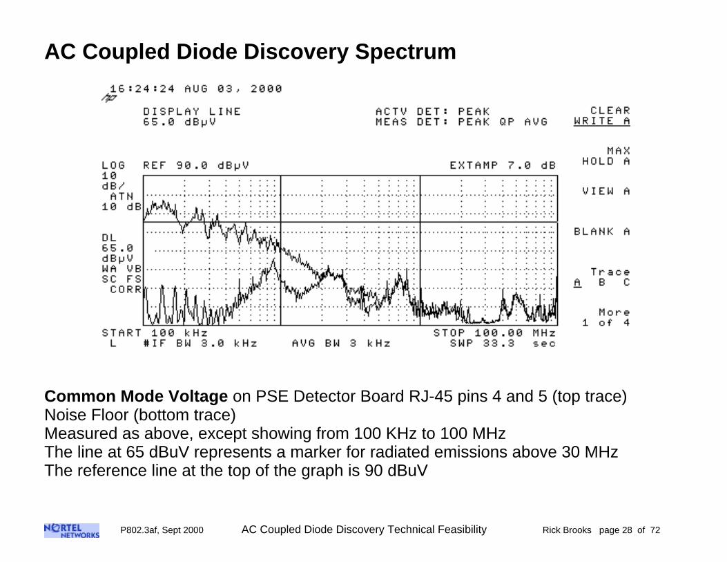
Common Mode Voltage on PSE Detector Board RJ-45 pins 4 and 5 (top trace)Noise Floor (bottom trace)Measured as above, except showing from 100 KHz to 100 MHzThe line at 65 dBuV represents a marker for radiated emissions above 30 MHzThe reference line at the top of the graph is 90 dBuV
P802.3af, Sept 2000 AC Coupled Diode Discovery Technical Feasibility Rick Brooks page 29 of 72
AC Coupled Diode Discovery Spectrum
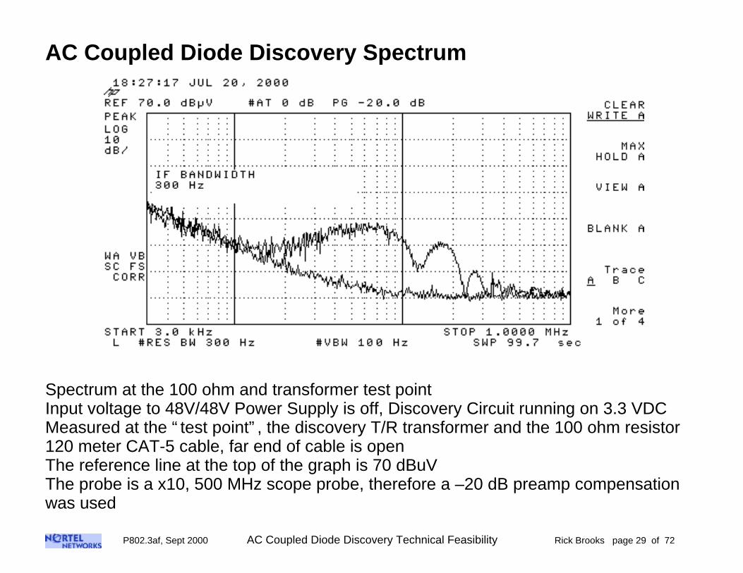
Spectrum at the 100 ohm and transformer test pointInput voltage to 48V/48V Power Supply is off, Discovery Circuit running on 3.3 VDCMeasured at the “ test point” , the discovery T/R transformer and the 100 ohm resistor120 meter CAT-5 cable, far end of cable is openThe reference line at the top of the graph is 70 dBuVThe probe is a x10, 500 MHz scope probe, therefore a –20 dB preamp compensationwas used

P802.3af, Sept 2000 AC Coupled Diode Discovery Technical Feasibility Rick Brooks page 30 of 72
EMC Tests

P802.3af, Sept 2000 AC Coupled Diode Discovery Technical Feasibility Rick Brooks page 31 of 72
Radiated Emissions and Susceptibility Testing of the DiodeDiscovery Prototype Board Set
Radiated Emissions Test Setups:
RCVR
Faraday Cage
60 meterCAT-5cable
10meters
HPDC
PowerSupply
AC Coupled DiodeDTE Detector
Board
RJ-45
LineFilter
120 VAC
12
3
45
6
78
12
3
45
6
78
Radiated Emissions Test Setup,with a
Continuous Discovery ProcessAnechoic Chamber
Radiated Emissions Test Setup for Continuous Discovery Mode
In the “ continuous” discovery mode, the far end of the CAT-5 cable is open, thereforethe discovery process continues to run. This mode is the best to see how much RFenergy is radiated due to this process.

P802.3af, Sept 2000 AC Coupled Diode Discovery Technical Feasibility Rick Brooks page 32 of 72
Radiated Emissions Test Setups (cont):
RCVR
Faraday Cage
60 meterCAT-5cable
10meters
HPDC
PowerSupply
AC Coupled DiodeDTE Detector
Board
RJ-45
LineFilter
120 VAC
AC CoupledDiode
DTE Load Board
12
3
45
6
78
12
3
45
6
78
Anechoic Chamber
Radiated Emissions Test Setupwhile Applying 48 VDC DTE Power
DCLoad
Radiated Emissions Test Setup for DTE Power Delivery Mode
Following the discovery process, DTE power is delivered continuously into the load, inthis case the load receives 7.87 watts, whereas the PSE (detector board) delivers 8.69watts.

P802.3af, Sept 2000 AC Coupled Diode Discovery Technical Feasibility Rick Brooks page 33 of 72
Radiated Emissions Test Setup, 10 meter Anechoic Chamber

P802.3af, Sept 2000 AC Coupled Diode Discovery Technical Feasibility Rick Brooks page 34 of 72
Radiated Emissions with Continuous Coupled Diode Discovery Running
Legend:
Class A Limit solid violet line6dB margin to Class A Limit dotted violet lineClass B Limit solid black line6dB margin to Class B Limit dotted light blue lineContinuous Diode Discovery solid dark blue traceNoise Floor of chamber and receiver solid black trace
50.0
40.0
30.0
20.0
10.0
0.0
-10.0
-20.0 127.1 224.2 321.3 418.4 515.5 612.6 709.7 806.8 903.9
60.0 [dBuV/m]
08/23/2000 08:38:37
30.0 1000.0Frequency [MHz]
50.0
40.0
30.0
20.0
10.0
0.0
-10.0
-20.0127.1 224.2 321.3 418.4 515.5 612.6 709.7 806.8 903.9
60.0[dBuV/m]
08/23/2000 08:30:17
30.0 1000.0Frequency [MHz]
P802.3af, Sept 2000 AC Coupled Diode Discovery Technical Feasibility Rick Brooks page 35 of 72
40.0
30.0
20.0
10.0
0.0
-10.0
-20.0
-30.0127.1
224.2
321.3
418.4
515.5
612.6
709.7
806.8
903.9
50.0[dBuV/m]
08/23/200009:07:17
30.0
1000.0Frequency
[MHz]
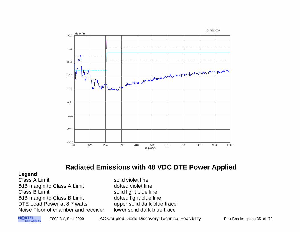
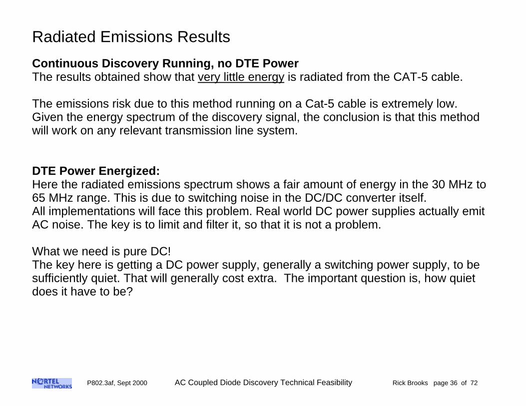
Radiated Emissions with 48 VDC DTE Power AppliedLegend:Class A Limit solid violet line6dB margin to Class A Limit dotted violet lineClass B Limit solid light blue line6dB margin to Class B Limit dotted light blue lineDTE Load Power at 8.7 watts upper solid dark blue traceNoise Floor of chamber and receiver lower solid dark blue trace
P802.3af, Sept 2000 AC Coupled Diode Discovery Technical Feasibility Rick Brooks page 36 of 72
Radiated Emissions Results
Continuous Discovery Running, no DTE PowerThe results obtained show that very little energy is radiated from the CAT-5 cable.
The emissions risk due to this method running on a Cat-5 cable is extremely low.Given the energy spectrum of the discovery signal, the conclusion is that this methodwill work on any relevant transmission line system.
DTE Power Energized:Here the radiated emissions spectrum shows a fair amount of energy in the 30 MHz to65 MHz range. This is due to switching noise in the DC/DC converter itself.All implementations will face this problem. Real world DC power supplies actually emitAC noise. The key is to limit and filter it, so that it is not a problem.
What we need is pure DC!The key here is getting a DC power supply, generally a switching power supply, to besufficiently quiet. That will generally cost extra. The important question is, how quietdoes it have to be?
P802.3af, Sept 2000 AC Coupled Diode Discovery Technical Feasibility Rick Brooks page 37 of 72
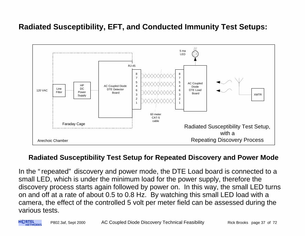
Radiated Susceptibility, EFT, and Conducted Immunity Test Setups:
Radiated Susceptibility Test Setup,with a
Repeating Discovery Process
Faraday Cage
60 meterCAT-5cable
HPDC
PowerSupply
AC Coupled DiodeDTE Detector
Board
RJ-45
LineFilter
120 VAC
AC CoupledDiode
DTE Load Board
12
3
45
6
78
12
3
45
6
78
Anechoic Chamber
XMTR
5 maLED
Radiated Susceptibility Test Setup for Repeated Discovery and Power Mode
In the “ repeated” discovery and power mode, the DTE Load board is connected to asmall LED, which is under the minimum load for the power supply, therefore thediscovery process starts again followed by power on. In this way, the small LED turnson and off at a rate of about 0.5 to 0.8 Hz. By watching this small LED load with acamera, the effect of the controlled 5 volt per meter field can be assessed during thevarious tests.
P802.3af, Sept 2000 AC Coupled Diode Discovery Technical Feasibility Rick Brooks page 38 of 72
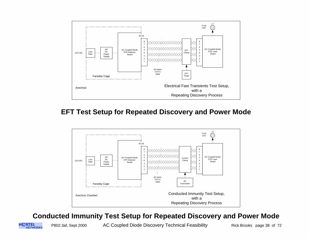
Electrical Fast Transients Test Setup,with a
Repeating Discovery Process
Faraday Cage
60 meterCAT-5cable
HPDC
PowerSupply
LineFilter
120 VAC
AnechoicChamber
5 maLED
12
3
45
6
78
AC Coupled DiodeDTE Detector
Board
RJ-45
12
3
45
6
78
AC Coupled DiodeDTE Load
Board
EFTClamp
EFTTester
EFT Test Setup for Repeated Discovery and Power Mode
Conducted Immunity Test Setup,with a
Repeating Discovery Process
Faraday Cage
60 meterCAT-5cable
HPDC
PowerSupply
LineFilter
120 VAC
Anechoic Chamber
5 maLED
12
3
45
6
78
AC Coupled DiodeDTE Detector
Board
RJ-45
12
3
45
6
78
AC Coupled DiodeDTE Load
Board
CurrentClamp
RFTransmitter
Conducted Immunity Test Setup for Repeated Discovery and Power Mode

P802.3af, Sept 2000 AC Coupled Diode Discovery Technical Feasibility Rick Brooks page 39 of 72
Radiated Susceptibility Test Setup, 10 meter Anechoic Chamber
Radiated Susceptibility Test
DTE Load Board with LED load below the minimum load

P802.3af, Sept 2000 AC Coupled Diode Discovery Technical Feasibility Rick Brooks page 40 of 72
Electrical Fast Transients Test Setup, 10 meter Anechoic Chamber

P802.3af, Sept 2000 AC Coupled Diode Discovery Technical Feasibility Rick Brooks page 41 of 72
Conducted Immunity Test Setup, 3 meter Anechoic Chamber

P802.3af, Sept 2000 AC Coupled Diode Discovery Technical Feasibility Rick Brooks page 42 of 72
EMC Susceptibility and Immunity Results:
Radiated Susceptibility:Tested from 80 MHz to 1 GHz at 5 volts per meter Test Passed, no effect seen on discovery/power cycle
Electrical Fast Transients:Tested using 500V pulses and the capacitive clampfixture to the CAT-5 cable Test Passed, no effect seen on discovery/power cycle
Conducted Immunity:Tested from 150 KHz to 80 MHz at 3 volts field strength Test Passed, no effect seen on discovery/power cycle
Summary:
Discovery Process:The discovery process tested on the prototype board has an extremely small level of radiated emissions.All of the immunity and susceptibility tests passed, although further testing is needed to find the margin to thesetests.
Power Delivery:The DTE power supply does have some output noise that creates radiated emissions, although this prototypepasses Class A, it does not pass Class B. The output switching noise of the power supply must be specified,and represents an area of risk.All of the immunity and susceptibility tests passed, although further testing is needed to find the margin to thesetests. Of particular interest will be sending power and data at the same time.

P802.3af, Sept 2000 AC Coupled Diode Discovery Technical Feasibility Rick Brooks page 43 of 72
Common Mode Noise RejectionTest

P802.3af, Sept 2000 AC Coupled Diode Discovery Technical Feasibility Rick Brooks page 44 of 72
Common Mode Noise Rejection Test
AC Coupled DiodeDTE Detector
Board
Powered
Un-Powered
J1
J2
AC Coupled DiodeDTE Load
Board
Powered
Un-Powered
DC LoadJ1
J2
RFGnerator
Scope
CAT-5 Cable
20 cm
Campbell ClampCommon Mode Injector
ETS Model CC-101
Ferrites
5 maLED
Common Mode Noise Injection Test
This test and fixture are outlined in 802.3 (1999), part 40.6.1.3.3, and Annex 40BI’m looking for any signs of inhibited discovery.
P802.3af, Sept 2000 AC Coupled Diode Discovery Technical Feasibility Rick Brooks page 45 of 72
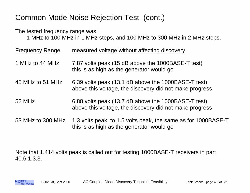
Common Mode Noise Rejection Test (cont.)
The tested frequency range was:1 MHz to 100 MHz in 1 MHz steps, and 100 MHz to 300 MHz in 2 MHz steps.
Frequency Range measured voltage without affecting discovery
1 MHz to 44 MHz 7.87 volts peak (15 dB above the 1000BASE-T test)this is as high as the generator would go
45 MHz to 51 MHz 6.39 volts peak (13.1 dB above the 1000BASE-T test)above this voltage, the discovery did not make progress
52 MHz 6.88 volts peak (13.7 dB above the 1000BASE-T test)above this voltage, the discovery did not make progress
53 MHz to 300 MHz 1.3 volts peak, to 1.5 volts peak, the same as for 1000BASE-Tthis is as high as the generator would go
Note that 1.414 volts peak is called out for testing 1000BASE-T receivers in part40.6.1.3.3.

P802.3af, Sept 2000 AC Coupled Diode Discovery Technical Feasibility Rick Brooks page 46 of 72
Common Mode Noise Rejection Test (cont.)
The setup was similar to the one used in the radiated susceptibility tests, above. Namelythat that small (5 ma) LED load, below the minimum load, was used to monitor whetheror not discovery and power were successful. Also, the “ spare” LED on the detectorboard was visually monitored for any influence upon any single discovery frame. ThisLED is turned after any discovery frame where either an open circuit or a short circuit isdetected. A further note is that for this test, unlike the EMC tests, the detector boardwas sitting on a bench, not in a faraday cage.
Result:There was no noticeable effect upon the ability to perform discovery or to power up at orbelow the voltage levels listed above.
Only at frequencies between 45 MHz and 52 MHz, did I have an RF generator thatcould output enough power to cause discovery to fail.
At frequencies that I could cause discovery to fail, the voltage required was at least 13dB higher than is called out for 1000BASE-T tests in IEEE802.3, part 40.6.1.3.3.

P802.3af, Sept 2000 AC Coupled Diode Discovery Technical Feasibility Rick Brooks page 47 of 72
Category 3 Cable Tests
P802.3af, Sept 2000 AC Coupled Diode Discovery Technical Feasibility Rick Brooks page 48 of 72
Category 3 Cable Tests
Below are the results of discovery using the AC coupled Diode method that I describedin May 2000 and July 2000 using Cat 3 cable, and running on the evaluation prototypeboards.The results are shown for 98 meters, and 304 meters of CAT-3 cable.In both cases the discovery worked properly for the 10 times that I tried it.In addition, there were 15 inch clip leads on each end to patch into the wire.
Summary:
I think this data shows that the diode method will work for Cat 3 cable, and that theresults are very similar to that of Cat 5 cable. Due to the limited bandwidth required bythe shaped pulses, the discovery process is not that particular as to the transmissionmedium.

P802.3af, Sept 2000 AC Coupled Diode Discovery Technical Feasibility Rick Brooks page 49 of 72
CAT-3 Cable Tests
AC Coupled Diode Discovery, Non-conducting DirectionCAT 3 Cable at 98 meters, plus two 15” clip leads at each end of the cableTop trace: drive signal, 1 volt/divBottom trace: receive signal, 1 volt/div

P802.3af, Sept 2000 AC Coupled Diode Discovery Technical Feasibility Rick Brooks page 50 of 72
CAT-3 Cable Tests
AC Coupled Diode Discovery, Conducting DirectionCAT 3 Cable at 98 meters, plus two 15” clip leads at each end of the cableTop trace: drive signal, 1 volt/divBottom trace: receive signal, 1 volt/div

P802.3af, Sept 2000 AC Coupled Diode Discovery Technical Feasibility Rick Brooks page 51 of 72
CAT-3 Cable Tests
AC Coupled Diode Discovery, Non-conducting DirectionCAT 3 Cable, 304 meters, plus two 15” clip leads at each end of the cableTop trace: drive signal, 1 volt/divBottom trace: receive signal, 1 volt/div
P802.3af, Sept 2000 AC Coupled Diode Discovery Technical Feasibility Rick Brooks page 52 of 72
CAT-3 Cable Tests
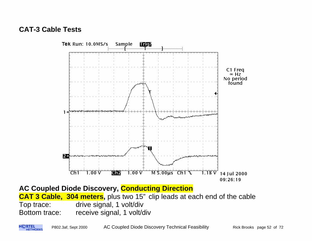
AC Coupled Diode Discovery, Conducting DirectionCAT 3 Cable, 304 meters, plus two 15” clip leads at each end of the cableTop trace: drive signal, 1 volt/divBottom trace: receive signal, 1 volt/div

P802.3af, Sept 2000 AC Coupled Diode Discovery Technical Feasibility Rick Brooks page 53 of 72
AC Coupled Diode DiscoveryCrosstalk

P802.3af, Sept 2000 AC Coupled Diode Discovery Technical Feasibility Rick Brooks page 54 of 72
Two Simultaneous Discovery Process on One CAT-5 cable
Test SetupPair to Pair Crosstalk
withDiscovery Process
AC Coupled DiodeDTE Detector
Board
RJ-45
AC Coupled DiodeDTE Detector
Board
RJ-45
CAT-5cable
12
3
45
6
78
12
3
45
6
78
12
3
45
6
78
AC Coupled DiodeDTE Load
Board
12
3
45
6
78
12
3
45
6
78
Pair to Pair Crosstalk Test Setup
P802.3af, Sept 2000 AC Coupled Diode Discovery Technical Feasibility Rick Brooks page 55 of 72
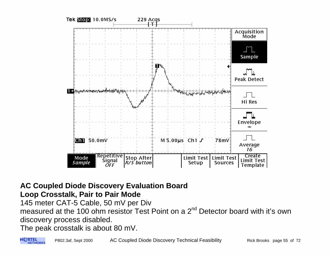
AC Coupled Diode Discovery Evaluation BoardLoop Crosstalk, Pair to Pair Mode145 meter CAT-5 Cable, 50 mV per Divmeasured at the 100 ohm resistor Test Point on a 2nd Detector board with it’s owndiscovery process disabled.The peak crosstalk is about 80 mV.

P802.3af, Sept 2000 AC Coupled Diode Discovery Technical Feasibility Rick Brooks page 56 of 72
Two Simultaneous Discovery Process on One CAT-5 cable
Test SetupTwo Simultaneous Discovery Processes
pins 4-5, 7-8 and pins 1-2, 3-6
AC Coupled DiodeDTE Detector
Board
RJ-45
AC Coupled DiodeDTE Detector
Board
RJ-45
CAT-5cable
12
3
45
6
78
12
3
45
6
78
12
3
45
6
78
12
3
45
6
78
AC CoupledDiode
DTE Load Board
12
3
45
6
78
AC CoupledDiode
DTE Load Board
12
3
45
6
781
2
3
45
6
78
12
3
45
6
78
Two Simultaneous Discovery ProcessesTest Setup

P802.3af, Sept 2000 AC Coupled Diode Discovery Technical Feasibility Rick Brooks page 57 of 72
Two Simultaneous Discovery Process on One CAT-5 cable
This test helps to demonstrate that two separate and independent discovery processescan take place on two different pair sets on a CAT-5 cable with very little crosstalk.
Task: determine the max cable length under the following conditions with the criteria of20 successful power on cycles without an interruption or noticeable delay:
Results:
Discovery Process Running on 1st Detector Board OnlyMaximum CAT-5 cable is 140m + 130m + 120m + 50m (including 6 RJ-45 mated pairs) =440 meters
Discovery Process Running on 2nd Detector Board OnlyMaximum CAT-5 cable is 140m + 90m + 30m + 5m (including 6 RJ-45 mated pairs) =265 meters
Discovery Process Running Simultaneously on both 1st and 2nd Detector Boards1st Detector maximum cable is 140m + 130m + 100m + 5m (including 6 RJ-45 mated pairs) =375 meters a 14.8% reduction in workable cable length
2nd Detector maximum cable is 140m + 90m + 30m + 5m (including 6 RJ-45 mated pairs) =265 meters no reduction in workable cable length
Considering the cable length, this is not much effect

P802.3af, Sept 2000 AC Coupled Diode Discovery Technical Feasibility Rick Brooks page 58 of 72
AC Coupled Diode Discovery,Pair to Pair Mode Open Circuit Crosstalk
Pair to pair open circuit crosstalk has been measured using the test setup shown below.
The DTE discovery prototype board was running the continuous discovery process onpins 4-5 and 7-8. The pair to pair crosstalk was then measured with 1-2 shorted, and 3-6 shorted as shown. Pins 1-2 and 3-6 were otherwise not connected, as shown below.
A differential probe was used to measure at 1-2 to 3-6, as shown below, the waveformshows a peak voltage of about 400 mV on a cable length of 145 meters.
Measurement SetupPair to Pair Mode
Open Circuit Crosstalk
AC Coupled DiodeDTE Detector
Board
RJ-45
145 meterCAT-5cable
12
3
45
6
78
12
3
45
6
78
AC Coupled DiodeDTE Load
Board
12
3
45
6
78
12
3
45
6
78
+-
Scope
DifferentialProbe
RJ-45 RJ-45
Pair to Pair Mode Open Circuit Crosstalk Test Setup
P802.3af, Sept 2000 AC Coupled Diode Discovery Technical Feasibility Rick Brooks page 59 of 72
AC Coupled Diode Discovery,Pair to Pair Mode Open Circuit Crosstalk
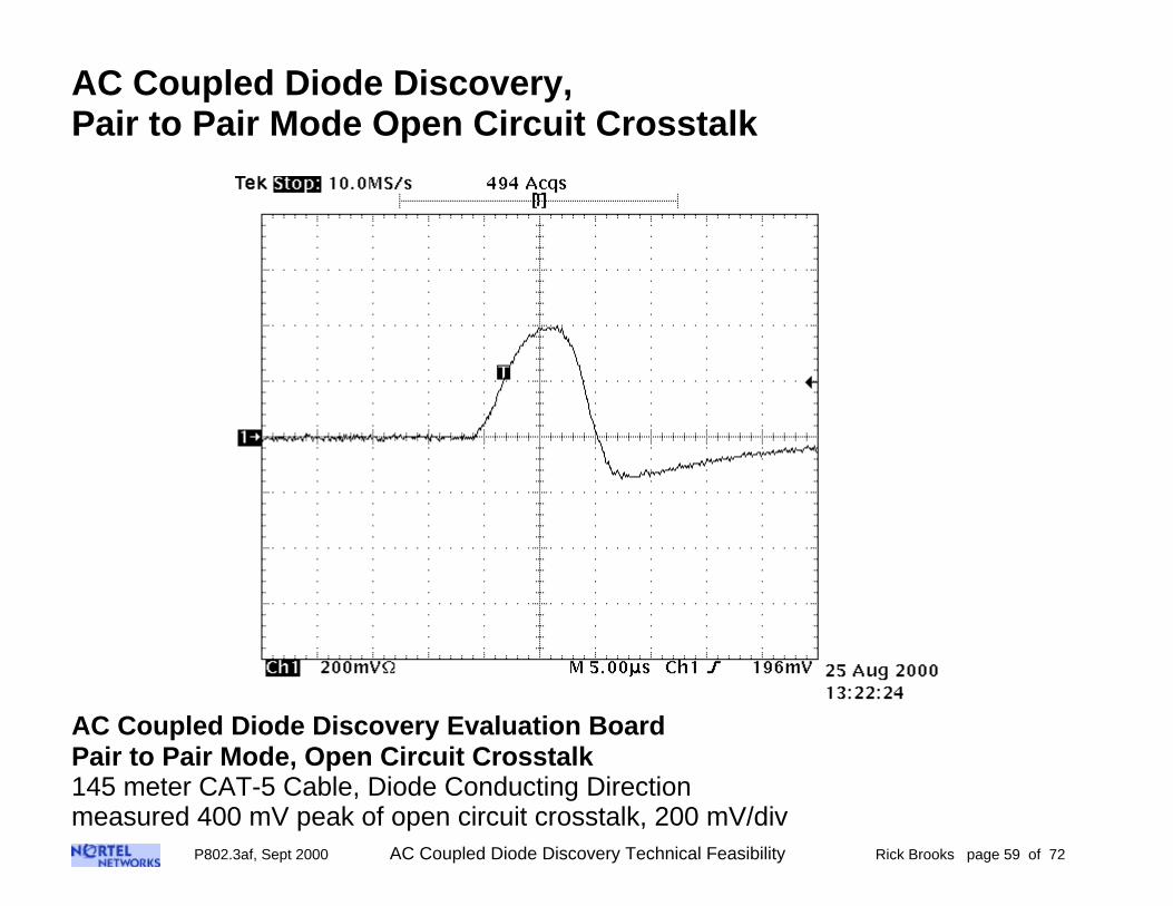
AC Coupled Diode Discovery Evaluation BoardPair to Pair Mode, Open Circuit Crosstalk145 meter CAT-5 Cable, Diode Conducting Directionmeasured 400 mV peak of open circuit crosstalk, 200 mV/div

P802.3af, Sept 2000 AC Coupled Diode Discovery Technical Feasibility Rick Brooks page 60 of 72
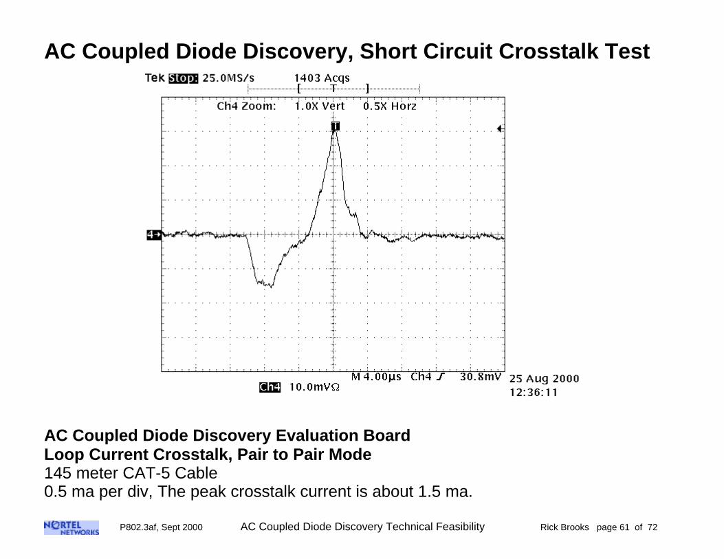
AC Coupled Diode Discovery, Short Circuit Crosstalk Test
In this test the discovery process runs continuously on pins 4-5 and 7-8. The pair to pairmode crosstalk is measured while the 1-2 and 3-6 set of pairs is shorted at the near endof the cable, as shown below.
The current probe amplifier is set for a sensitivity of 5 ma per div, so the net result isthat 0.5 ma per div is displayed on the scope.
Measurement SetupPair to Pair Mode
Short Circuit Current Crosstalk
AC Coupled DiodeDTE Detector
Board
RJ-45
CAT-5cable
12
3
45
6
78
12
3
45
6
78
AC Coupled DiodeDTE Load
Board
12
3
45
6
78
12
3
45
6
78
TekCurrent
Probe Amp
10 Turns
Current Probe
Set at 5 ma per Div
Scope50 Ohm
P802.3af, Sept 2000 AC Coupled Diode Discovery Technical Feasibility Rick Brooks page 61 of 72
AC Coupled Diode Discovery, Short Circuit Crosstalk Test
AC Coupled Diode Discovery Evaluation BoardLoop Current Crosstalk, Pair to Pair Mode145 meter CAT-5 Cable0.5 ma per div, The peak crosstalk current is about 1.5 ma.

P802.3af, Sept 2000 AC Coupled Diode Discovery Technical Feasibility Rick Brooks page 62 of 72
Discovery Impact on Data Integrity

P802.3af, Sept 2000 AC Coupled Diode Discovery Technical Feasibility Rick Brooks page 63 of 72
Discovery Impact on 100 Mbps Data Integrity
In this test a 100 Mbps link cable length is increased until a fair number of CRC errorsare seen. Then, through a repetition of the same experiment, a comparison is madebetween the 100 Mbps link without discovery running, and with discovery running.In this case the cable length is 150 meters with 8 RJ-45 connector pairs
Midspan Power Test Setup100 Mbps Full Duplex Data and
DTE power pins 4-5, 7-8
AC Coupled DiodeDTE Detector
Board
140 meterCAT-5 cable
Powered
Un-Powered
SmartBits7405
SmartBits7405
100 MbpsFull Duplex
100 MbpsFull Duplex
J1
J2
2 meterCAT-5 Patch Cable
5 meterCAT-5 Patch Cable
3 meterCAT-5 Patch Cable
RJ-45F to F
coupler
RJ-45F to F
coupler
DiscoveryPower(3.3V)
DTEPrimaryPower
(48 VDC)
Discovery Impact on Data Setup

P802.3af, Sept 2000 AC Coupled Diode Discovery Technical Feasibility Rick Brooks page 64 of 72
Discovery Impact on 100 Mbps Data IntegrityExperiment: send approximately 1 million packets, record the number of CRC’s
No Discovery, all Prototype power off:1st test: 1863 errors out of 1035280 frames: 1.7995 E-3 errors per frame2nd test: 1665 errors out of 1017255 frames: 1.6368 E-3 errors per frame3rd test: 3195 errors out of 1839308 frames: 1.7371 E-3 errors per frame4th test: 1640 errors out of 1021734 frames: 1.6051 E-3 errors per frame5th test: 1630 errors out of 1009676 frames: 1.6144 E-3 errors per frame
errors per frame:mean: 1.67858 E-3 standard deviation: 7.6564 E-5
Continuous Discovery, Prototype 3.3V power on:1st test: 1661 errors out of 1031436 frames: 1.6104 E-3 errors per frame2nd test: 2156 errors out of 1341906 frames: 1.6067 E-3 errors per frame3rd test: 1498 errors out of 1015143 frames: 1.4756 E-3 errors per frame4th test: 1601 errors out of 1022798 frames: 1.5653 E-3 errors per frame5th test: 1723 errors out of 1137458 frames: 1.5148 E-3 errors per frame
errors per frame:mean: 1.55456 E-3 standard deviation: 5.2474 E-5
This test shows very little statistical difference between no discovery and discovery

P802.3af, Sept 2000 AC Coupled Diode Discovery Technical Feasibility Rick Brooks page 65 of 72
Hazard Matrix Testing
P802.3af, Sept 2000 AC Coupled Diode Discovery Technical Feasibility Rick Brooks page 66 of 72
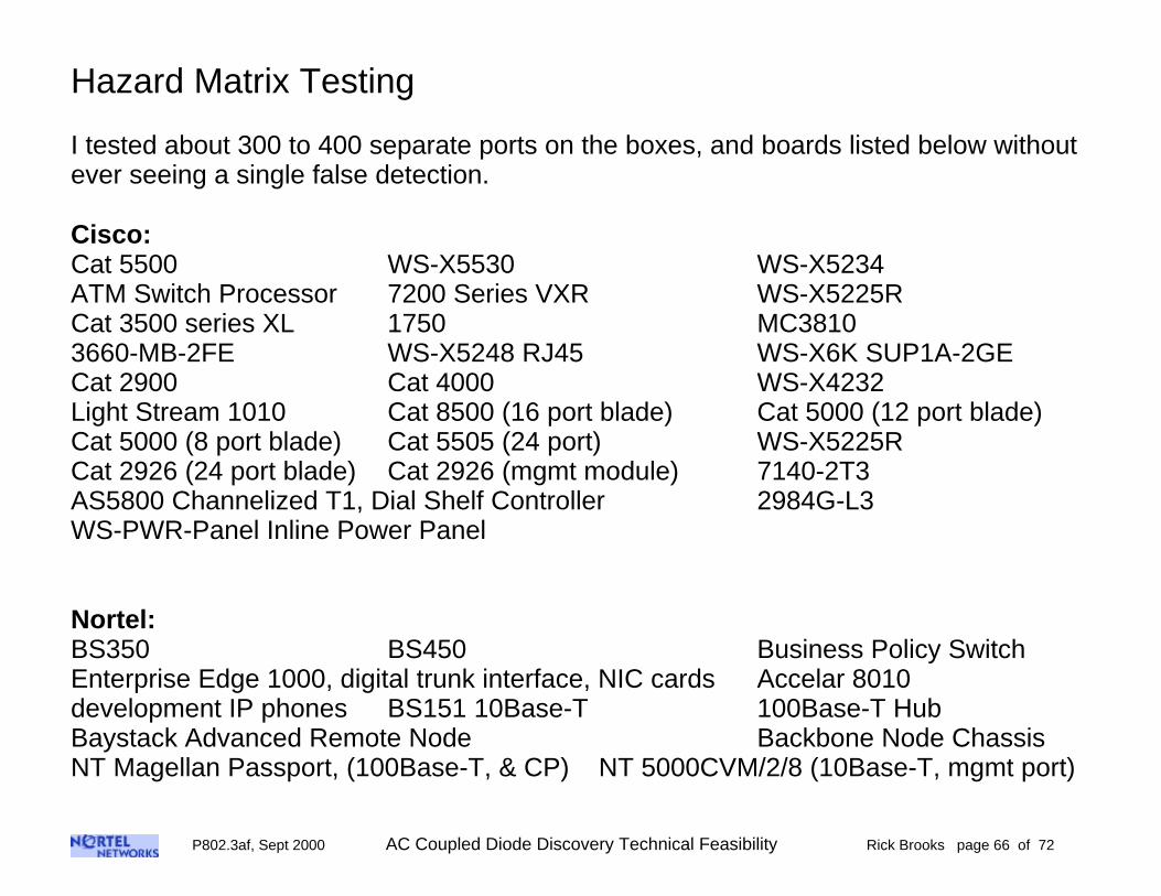
Hazard Matrix Testing
I tested about 300 to 400 separate ports on the boxes, and boards listed below withoutever seeing a single false detection.
Cisco:Cat 5500 WS-X5530 WS-X5234ATM Switch Processor 7200 Series VXR WS-X5225RCat 3500 series XL 1750 MC38103660-MB-2FE WS-X5248 RJ45 WS-X6K SUP1A-2GECat 2900 Cat 4000 WS-X4232Light Stream 1010 Cat 8500 (16 port blade) Cat 5000 (12 port blade)Cat 5000 (8 port blade) Cat 5505 (24 port) WS-X5225RCat 2926 (24 port blade) Cat 2926 (mgmt module) 7140-2T3AS5800 Channelized T1, Dial Shelf Controller 2984G-L3WS-PWR-Panel Inline Power Panel
Nortel:BS350 BS450 Business Policy SwitchEnterprise Edge 1000, digital trunk interface, NIC cards Accelar 8010development IP phones BS151 10Base-T 100Base-T HubBaystack Advanced Remote Node Backbone Node ChassisNT Magellan Passport, (100Base-T, & CP) NT 5000CVM/2/8 (10Base-T, mgmt port)

P802.3af, Sept 2000 AC Coupled Diode Discovery Technical Feasibility Rick Brooks page 67 of 72
Hazard Matrix Testing (cont.)
Nortel (cont):Development boards 10/100/1000… Netgear 10/100 SwitchesNetgear 10/100 NIC card
3Com:NBX 100, 3C10116 Digital Line Card10Base-T Hub card Superstack II Switch 9300Link Builder MSH/11 (12 port blade, mgmt blade)Superstack II Switch 3000 (12 ports)Core Builder 3500 (6 port blades, mgmt port, main blade)Cellplex 7000 Switch 16x16, mgmt portLinkswitch 1000 3C16900 (24 ports) Linkswitch 2700 (10 ports)FMS TP Hub (12 ports) FMS II (12 port and 24 port)Superstack II, 24 ports Link Switch 3000 (8 ports)Superstack II Netbuilder (3 ports) Pathbuilder S500 (2 ports)Superstack II Switch 3900 (36 ports) Switch 3000 (12 ports)
Cabletron:Switch 2200 (24 port) Switch 6000 (24 port blade)
P802.3af, Sept 2000 AC Coupled Diode Discovery Technical Feasibility Rick Brooks page 68 of 72
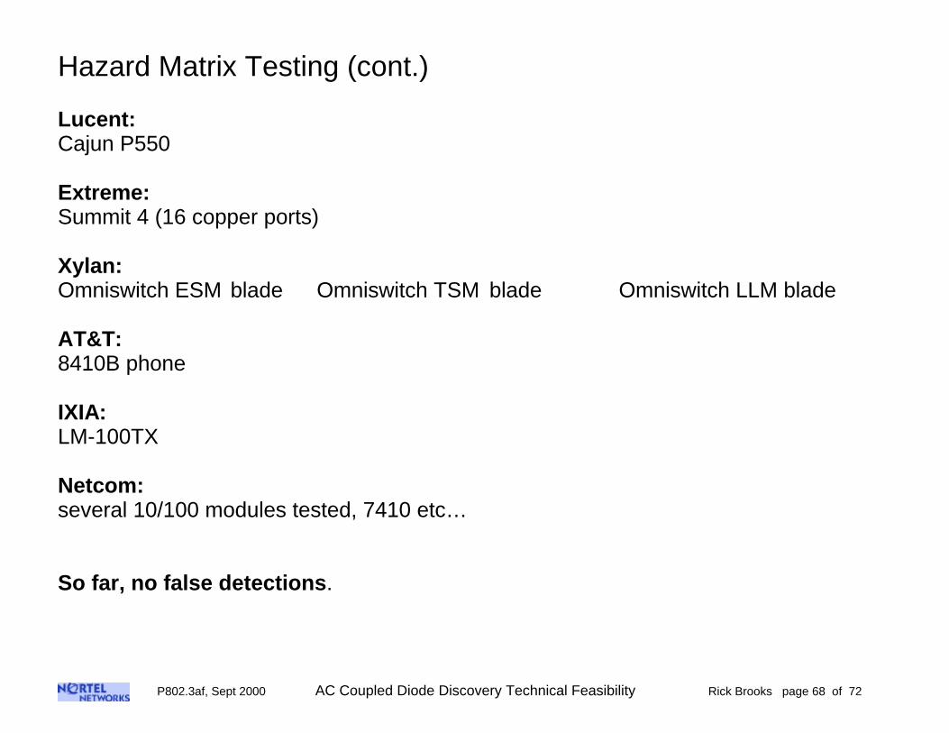
Hazard Matrix Testing (cont.)
Lucent:Cajun P550
Extreme:Summit 4 (16 copper ports)
Xylan:Omniswitch ESM blade Omniswitch TSM blade Omniswitch LLM blade
AT&T:8410B phone
IXIA:LM-100TX
Netcom:several 10/100 modules tested, 7410 etc…
So far, no false detections.

P802.3af, Sept 2000 AC Coupled Diode Discovery Technical Feasibility Rick Brooks page 69 of 72
Implementation Notes
The AC coupled diode discovery method has been demonstrated by this set ofevaluation boards running the referenced Verilog code. All of these elements are justexamples of one possible implementation, obviously not the only one. It is also quitepossible to implement this form of discovery into the DTE power circuit.
The IEEE802.3af DTE power spec should not specify:• how to implement a design• to use a coupling transformer• to use a PHY• to use a power supply• to use any specific type of component or topology
In almost all cases, these are really just implementation details.This demonstration is meant to show how practical this approach is.
The IEEE802.3af DTE power spec should specify:• the behavior for the PSE• what the acceptance template is for the PSE• the behavior for the PD• what the acceptance template is for the PD• the required elements to get all compliant PSE’s and PD’s to inter-operate

P802.3af, Sept 2000 AC Coupled Diode Discovery Technical Feasibility Rick Brooks page 70 of 72
Future Tests
• CAT-6 cable
• 25 pair cable
• Shielded UTP
• Campbell clamp common mode test at higher power
• Discovery process running simultaneously with data on the same wires
• More hazard matrix testing
• Further tests on the pair to pair mode coupling
• 1000BASE-T
• Immunity and susceptibility tests at higher levels

P802.3af, Sept 2000 AC Coupled Diode Discovery Technical Feasibility Rick Brooks page 71 of 72
AC Coupled Diode Discovery Conclusions
Robust• I have not been able to fool it into false discovery yet• Passes radiated susceptibility 5 volts per meter• Passes Electrical Fast Transients• Passes Conducted Immunity tests, treating the CAT-5 cable as a power line• Passes the Common Mode Noise Test for 1000BASE-T• Two simultaneous discovery processes can co-exist on a single CAT-5 cable• Works virtually identically on CAT-3• It works on most reasonable transmission lines, but it will not work on series
lumped elements, for instance a series 1000 µH element. This behavior will tendto reject misconnected lumped loads
Quiet• passes radiated emissions per EN55022• the discovery spectrum is limited due to the pulse shaping used• one discovery process on one pair set does not interfere with discovery on the
other pair set• discovery can co-exist with 100 Mbps data with little or no effect on the data• Discovery and DTE power share the same transmission mode – Pair to Pair
mode. This is different than true common mode, although like differential mode,Pair to Pair mode does couple into common mode to some extent
P802.3af, Sept 2000 AC Coupled Diode Discovery Technical Feasibility Rick Brooks page 72 of 72
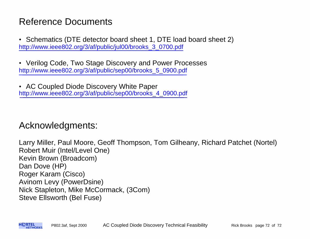
Reference Documents
• Schematics (DTE detector board sheet 1, DTE load board sheet 2)http://www.ieee802.org/3/af/public/jul00/brooks_3_0700.pdf
• Verilog Code, Two Stage Discovery and Power Processeshttp://www.ieee802.org/3/af/public/sep00/brooks_5_0900.pdf
• AC Coupled Diode Discovery White Paperhttp://www.ieee802.org/3/af/public/sep00/brooks_4_0900.pdf
Acknowledgments:
Larry Miller, Paul Moore, Geoff Thompson, Tom Gilheany, Richard Patchet (Nortel)Robert Muir (Intel/Level One)Kevin Brown (Broadcom)Dan Dove (HP)Roger Karam (Cisco)Avinom Levy (PowerDsine)Nick Stapleton, Mike McCormack, (3Com)Steve Ellsworth (Bel Fuse)