Embed Size (px)
Citation preview

Mot
herb
oard A8N32-SLI
Deluxe/WiFiDeluxe

2
T2280
© 2005

3

4
5
6

7
•
•
•
•
•
•
•
•
•
•
•
•

8
•
•
•
•
•
9
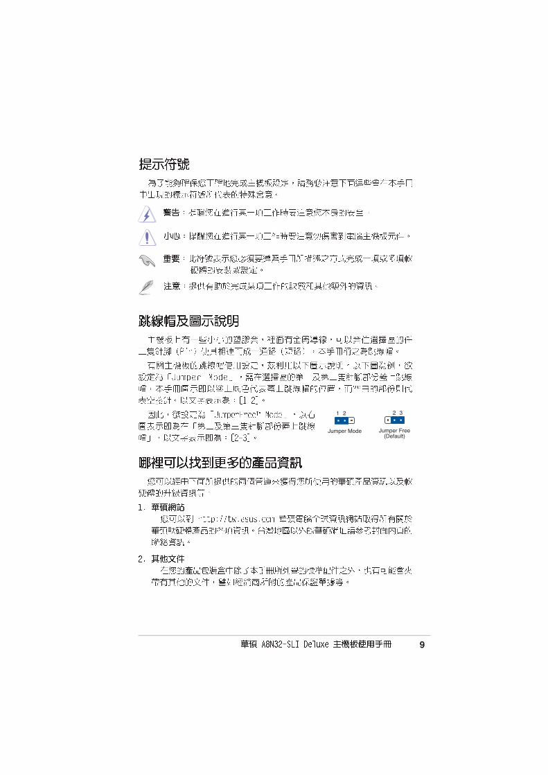
Jumper Free(Default)
2 3
Jumper Mode
1 2
10
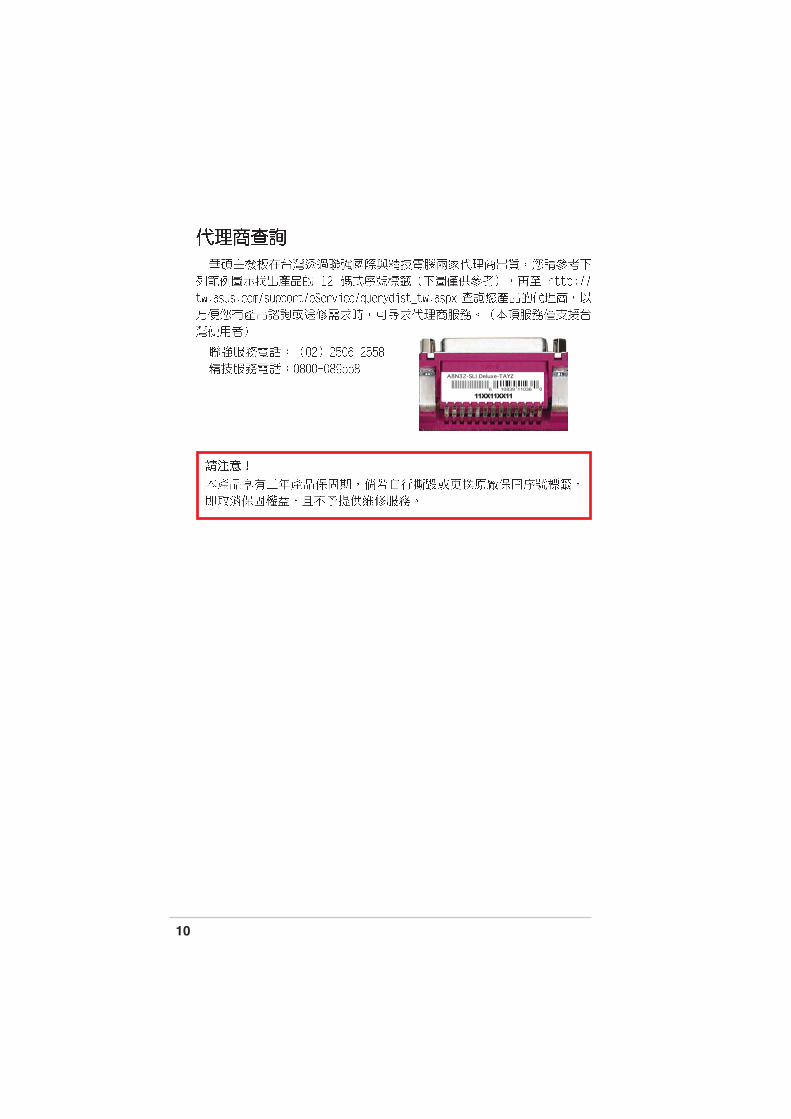
A8N32-SLI Deluxe-TAYZ
10839 110366 0
11XX11XX11

11
®
®
®
®

12

13
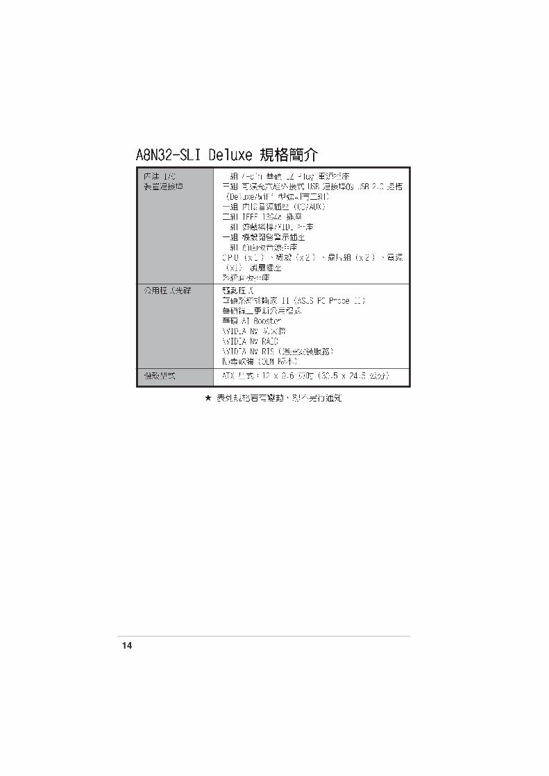
14


1-1

1-2
®
®
®
®

1-3

1-4
1-5

1-6

1-7

1-8


2-1
A8N
32-S
LI
®
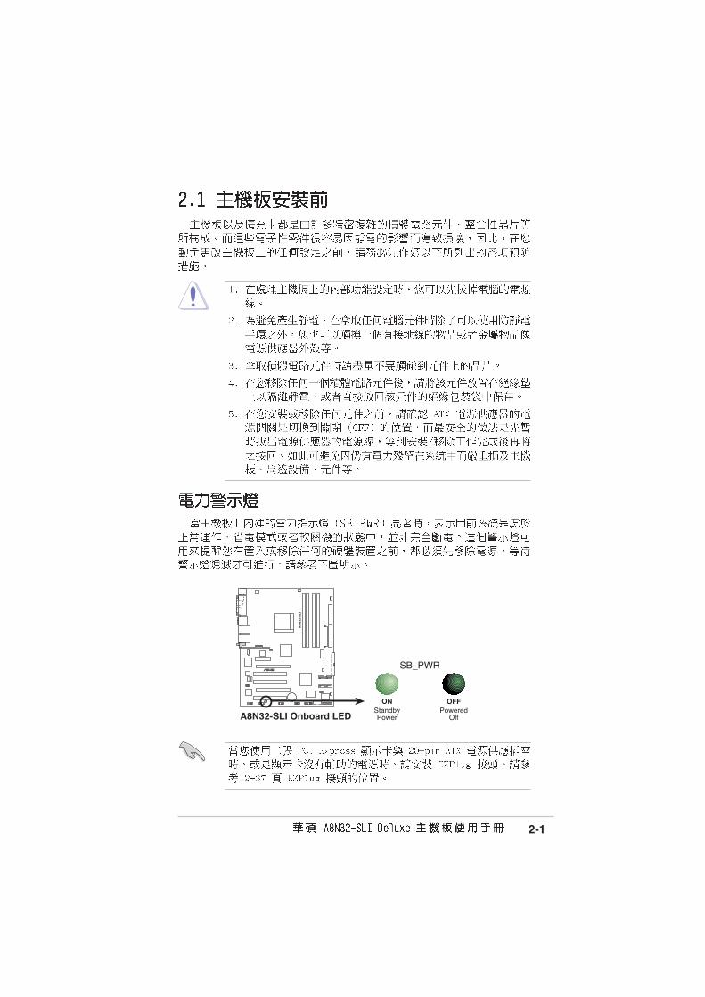
A8N32-SLI Onboard LED
SB_PWR
ONStandbyPower
OFFPowered
Off

2-2
A8N
32-S
LI
®
2-3

2-4
PANEL
A8N
32-S
LI
®
AUX
FP_AUDIO
GAME
CHASSIS
SE
C_I
DE
24.5cm (9.6in)
305c
m(1
20i
n)
CPU_FAN
DD
R D
IMM
_B1
(64
bit,1
84-p
in m
odul
e)
DD
R D
IMM
_A1
(64
bit,1
84-p
in m
odul
e)
DD
R D
IMM
_A2
(64
bit,1
84-p
in m
odul
e)
DD
R D
IMM
_B2
(64
bit,1
84-p
in m
odul
e)
PW
R_F
AN
LAN1_USB12
IE1394_1
CH
A_F
AN
2
FLO
PP
Y
SuperI/O 8Mb
BIOS
TSB43AB22A
PS/2KBMST: MouseB: Keyboard
PAR
AL
LE
L P
OR
T
SPDIF_O
SPDIF_O2
LAN2_USB34
CD
EZ
_PLU
G
ACL850
PCIEX16_1
PCI1
PCI2
Mar
vell
PH
Y
CLRTC
USB78USB56
SATA1SATA2
SATA4SATA3
SATA_RAID2
ES
ATA
NVIDIA®
CK804 SLI
SB_PWR
EAT
XP
WR
PR
I_ID
E
CR2032 3VLithium Cell
CMOS Power
CHA_FAN1
AUDIO
MarvellPCIE LAN
COM1
ATX12V
PCIEX4_1
IE1394_2
SB_FAN
WIFI_G_USB10(USB910)
Soc
ket 9
39
PCIEX16_2
PCI3
NVIDIA®
C51D
NB_FAN
2-5
2-6

2-7
®
®
®
®
A8N
32-S
LI
®
A8N32-SLI CPU Socket 939

2-8

2-9
2-10

2-11
A8N
32-S
LI
®
A8N32-SLI CPU fan connector
CPU_FAN
GN
D
Rot
atio
n+
12V
2-12
A8N
32-S
LI
®
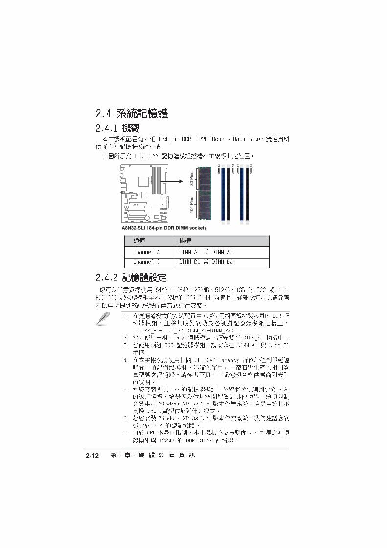
A8N32-SLI 184-pin DDR DIMM sockets
DIM
M_A
1
DIM
M_A
2
DIM
M_B
1
DIM
M_B
2
80 P
ins
104
Pin
s

2-13
2-14

2-15
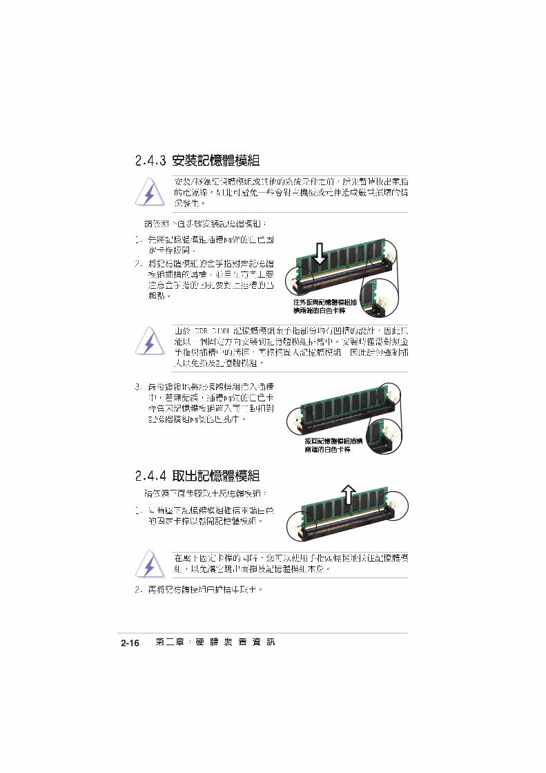
2-16

2-17
2-18
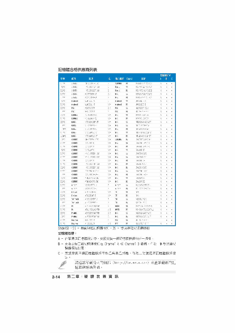
A B C

2-19
•
•
•
•
•
•

2-20
A8N
32-S
LI
®
A8N32-SLI Clear RTC RAM
CLRTC
Normal Clear CMOS(Default)
1 2 2 3
•
•
2-21
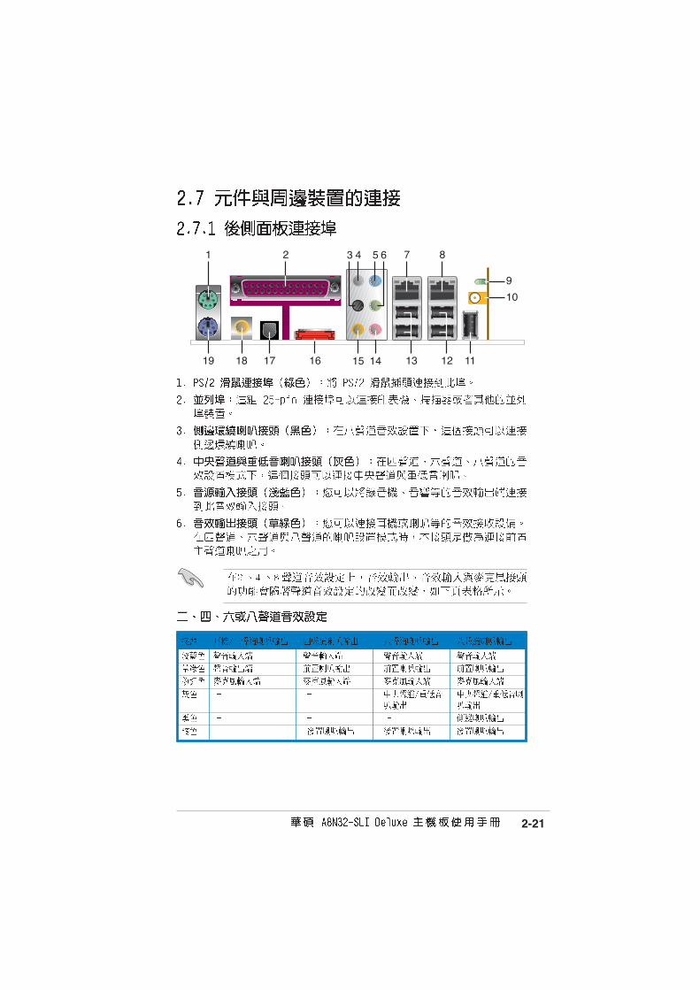
12
8
16
1
19
2
18 17 13
7
11
9
10
43 5 6
1415
2-22

2-23

2-24
•
•
A8N
32-S
LI
®
A8N32-SLI Floppy disk drive connector
s
PIN 1
FLOPPY
2-25
A8N
32-S
LI
®
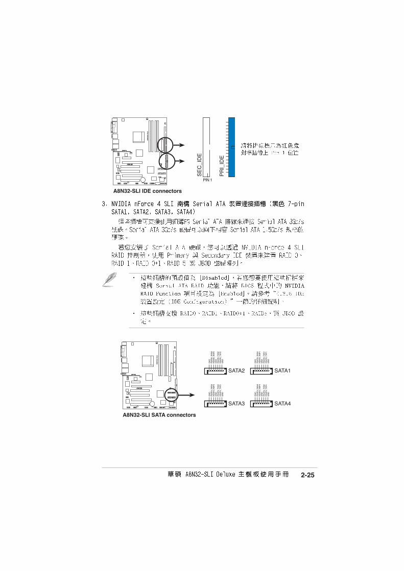
A8N32-SLI IDE connectors
PR
I_ID
E
PIN 1
SE
C_I
DE
A8N
32-S
LI
®
A8N32-SLI SATA connectors
SATA1SATA2
GN
DR
SAT
A_T
XP
4R
SAT
A_T
XN
4G
ND
RS
ATA
_RX
P4
RS
ATA
_RX
N4
GN
D
GN
DR
SAT
A_T
XP
3R
SAT
A_T
XN
3G
ND
RS
ATA
_RX
P3
RS
ATA
_RX
N3
GN
D
GN
DR
SAT
A_T
XP
2R
SAT
A_T
XN
2G
ND
RS
ATA
_RX
P2
RS
ATA
_RX
N2
GN
D
GN
DR
SAT
A_T
XP
1R
SAT
A_T
XN
1G
ND
RS
ATA
_RX
P1
RS
ATA
_RX
N1
GN
D
SATA3 SATA4

2-26
A8N
32-S
LI
®
A8N32-SLI SATA RAID connector
SATA_RAID2
GNDRSATA_TXP1RSATA_TXN1GNDRSATA_RXP1RSATA_RXN1GND
•
•
•

2-27
A8N
32-S
LI
®
A8N32-SLI USB 2.0 connectors
USB56
US
B+
5VU
SB
_P6-
US
B_P
6+G
ND
NC
US
B+
5VU
SB
_P5-
US
B_P
5+G
ND
1USB78
US
B+
5VU
SB
_P8-
US
B_P
8+G
ND
NC
US
B+
5VU
SB
_P7-
US
B_P
7+G
ND
1
A8N
32-S
LI
®
A8N32-SLI Internal audio connectors
AUX(white)
CD(black)
Right Audio Channel
Left Audio ChannelGroundGround
Right Audio Channel
Left Audio ChannelGroundGround
2-28
A8N
32-S
LI
®
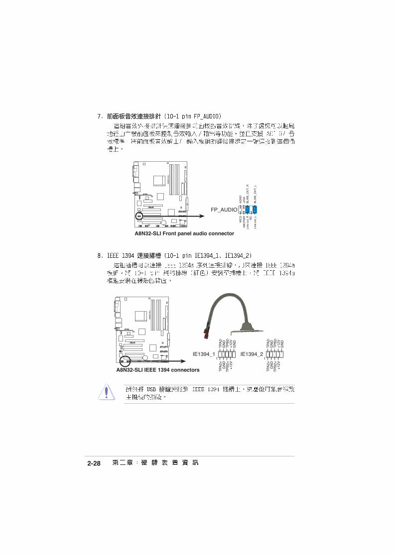
A8N32-SLI IEEE 1394 connectors
IE1394_21
TP
A2-
GN
DT
PB
2-+
12V
GN
D
TP
A2+
GN
DT
PB
2++
12V
IE1394_11
TP
A2-
GN
DT
PB
2-+
12V
GN
D
TP
A2+
GN
DT
PB
2++
12V
A8N
32-S
LI
®
A8N32-SLI Front panel audio connector
FP_AUDIO
BLI
NE
_OU
T_L
MIC
2
Line
out
_R
Line
out
_L
BLI
NE
_OU
T_R
NC
MIC
PW
R+
5VA
AG
ND

2-29
A8N
32-S
LI
®
A8N32-SLI Game connector
GAME+
5V+
5VJ2
B1
J2C
XM
IDI_
OU
TJ2
CY
J2B
2M
IDI_
IN
J1B
1J1
CX
GN
DG
ND
J1C
YJ1
B2
+5V
A8N
32-S
LI
®
A8N32-SLI COM port connector
PIN 1
COM1
2-30
A8N
32-S
LI
®
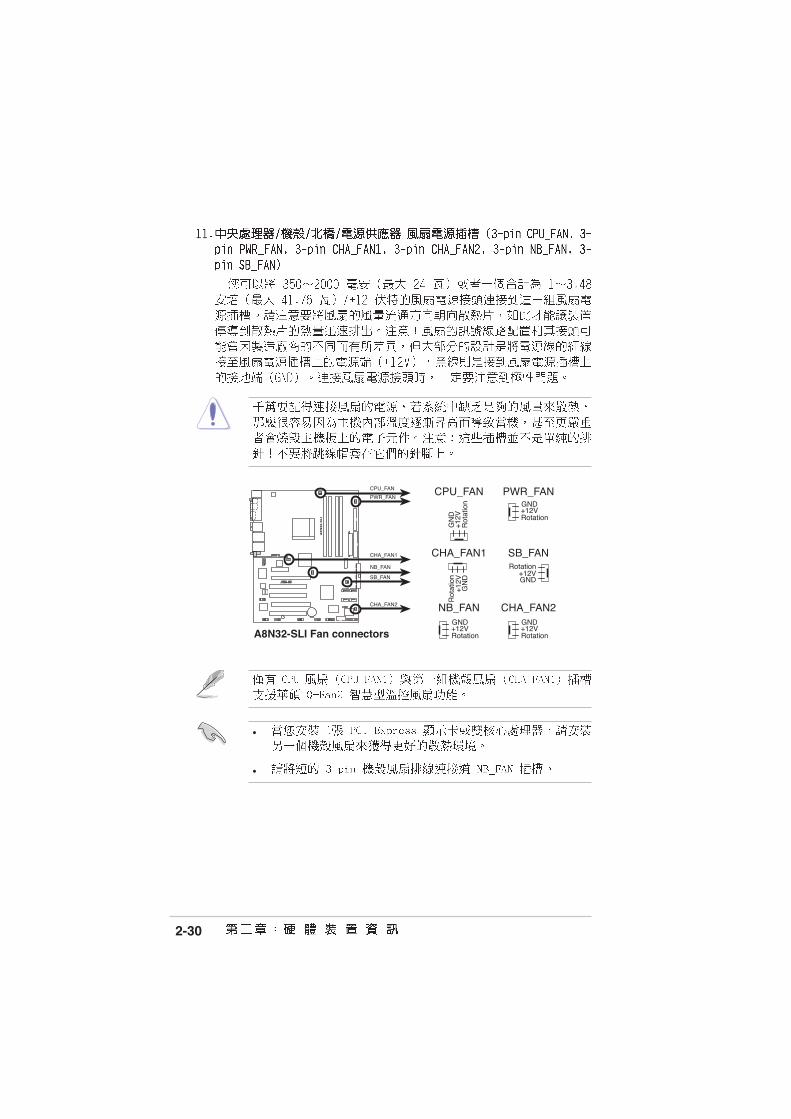
A8N32-SLI Fan connectors
CPU_FAN
CHA_FAN1
PWR_FAN
CHA_FAN2
GND
Rotation+12V
GND
Rotation+12V
CPU_FAN
PWR_FAN
CHA_FAN1
SB_FAN
SB_FAN
GN
D
Rot
atio
n+
12V
CHA_FAN2
GN
D
Rot
atio
n+
12V
GND
Rotation+12V
NB_FAN
NB_FANGND
Rotation+12V
•
•

2-31
A8N
32-S
LI
®
A8N32-SLI Chassis intrusion connector
CHASSIS
+5V
SB
_MB
Cha
ssis
Sig
nal
GN
D
(Default)
A8N
32-S
LI
®
A8N32-SLI ATX power connectors
EATXPWRATX12V
EZ_PLUG
+5VEZ_DETGND+12V
+12V DCGND
+12V DCGND
+3 Volts+3 VoltsGround+5 Volts
+5 VoltsGround
GroundPower OK+5V Standby+12 Volts
-5 Volts
+5 Volts
+3 Volts-12 VoltsGround
GroundGroundPSON#
Ground
+5 Volts
+12 Volts+3 Volts
+5 VoltsGround

2-32
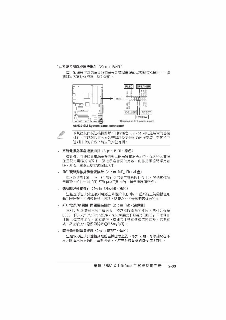
•
•
•
•
2-33
A8N
32-S
LI
®
A8N32-SLI System panel connector
* Requires an ATX power supply.
PANEL
PLE
D-
PW
R+
5V Spe
aker
Gro
und
RESET
Gro
und
Res
etG
roun
dG
roun
d
PWRSW
PLE
D+
IDE
_LE
D-
IDE
_LE
D+
IDE_LED
PLED SPEAKER
•
•
•
•
•
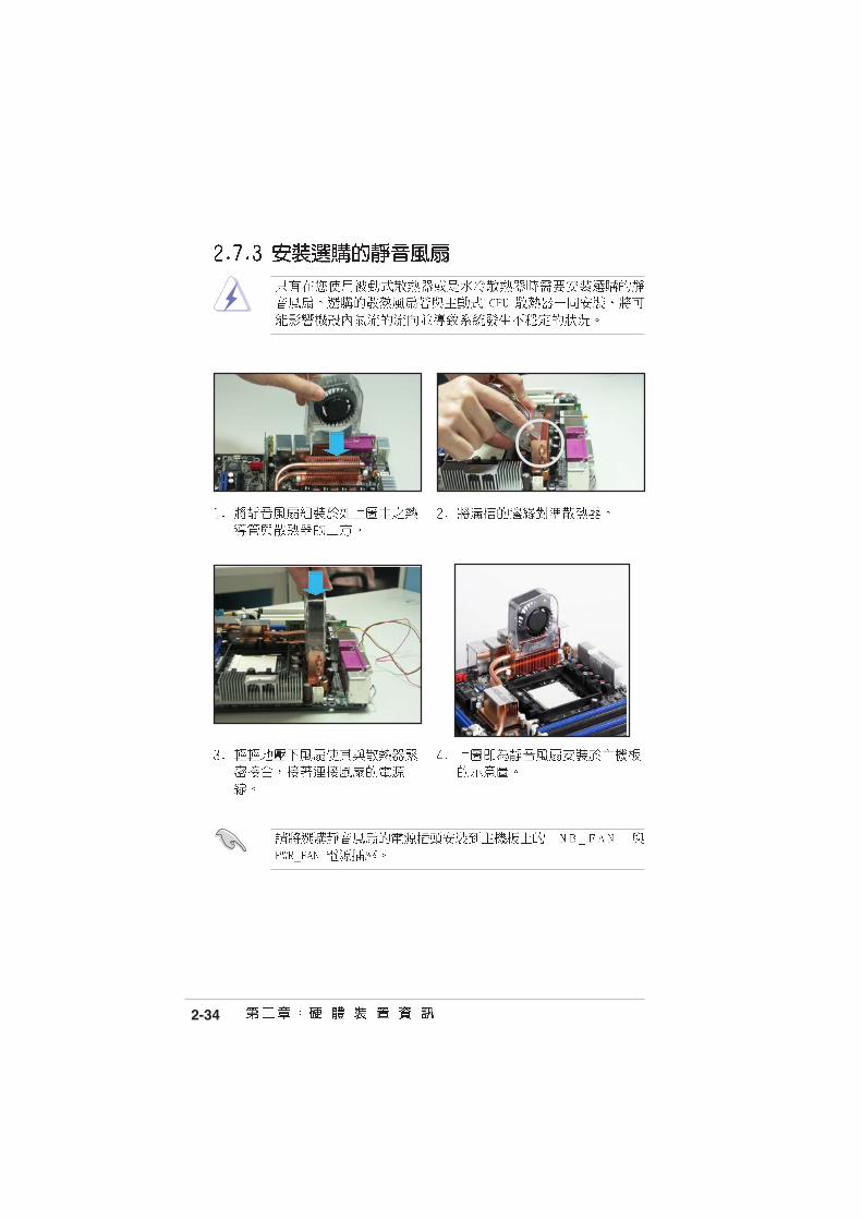
2-34

2-35

2-36


3-1

3-2


4-1
4-2
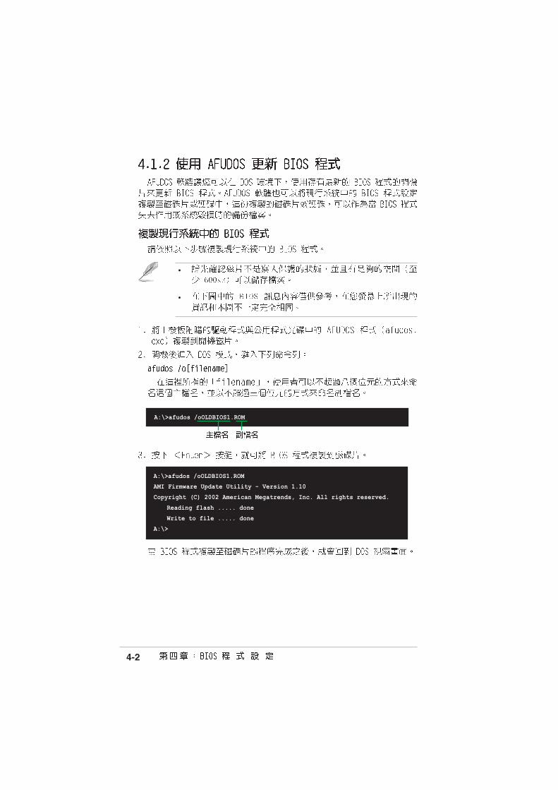
A:\>afudos /oOLDBIOS1.ROM
AMI Firmware Update Utility - Version 1.10
Copyright (C) 2002 American Megatrends, Inc. All rights reserved.
Reading flash ..... done
Write to file ..... done
A:\>
•
•
A:\>afudos /oOLDBIOS1.ROM
4-3
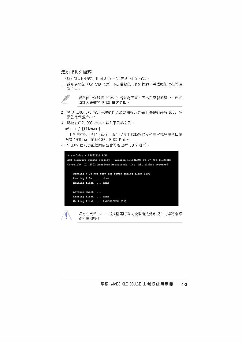
A:\>afudos /iA8N32SLI.ROM
AMI Firmware Update Utility - Version 1.10(ASUS V2.07 (03.11.24BB)
Copyright (C) 2002 American Megatrends, Inc. All rights reserved.
Warning!! Do not turn off power during flash BIOS
Reading file ..... done
Reading flash .... done
Advance Check ....
Erasing flash .... done
Writing flash .... 0x0008CC00 (9%)

4-4
A:\>afudos /iA8N32SLI.ROM
AMI Firmware Update Utility - Version 1.10(ASUS V2.07 (03.11.24BB)
Copyright (C) 2002 American Megatrends, Inc. All rights reserved.
Warning!! Do not turn off power during flash BIOS
Reading file ..... done
Reading flash .... done
Advance Check ....
Erasing flash .... done
Writing flash .... 0x0008CC00 (9%)
Verifying flash .. done
Please retart your computer
A:\>

4-5
Bad BIOS checksum. Starting BIOS recovery...
Checking for floppy...
Bad BIOS checksum. Starting BIOS recovery...
Checking for floppy...
Floppy found!
Reading file “A8N32SLI.ROM”. Completed.
Start flashing...

4-6
Bad BIOS checksum. Starting BIOS recovery...
Checking for floppy...
Bad BIOS checksum. Starting BIOS recovery...
Checking for floppy...
Floppy not found!
Checking for CD-ROM...
CD-ROM found.
Reading file “A8N32SLI.ROM”. Completed.
Start flashing...

4-7
EZFlash starting BIOS update
Checking for floppy...
•
•
EZFlash starting BIOS update
Checking for floppy...
Floppy found!
Reading file “A8N32SLI.ROM”. Completed.
Start erasing.......|
Start Programming...|
Flashed successfully. Rebooting.
4-8

4-9
4-10
4-11

4-12
Select Screen Select Item
+- Change FieldTab Select FieldF1 General HelpF10 Save and ExitESC Exit
v02.58 (C)Copyright 1985-2004, American Megatrends, Inc.
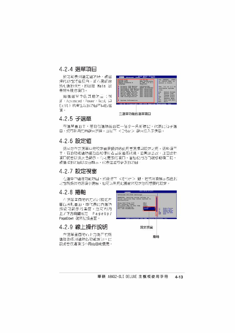
BIOS SETUP UTILITYMain Advanced Power Boot Exit
System Time [10:55:25]System Date [Mon 09/22/2005]Legacy Diskette A [1.44M, 3.5 in]Language [English]
Primary IDE Master [ST320410A]Primary IDE Slave [ASUS CD-S520/A]Secondary IDE Master [Not Detected]Secondary IDE Slave [Not Detected]First SATA Device [Not Detected]Second SATA Device [Not Detected]Third SATA Device [Not Detected]Fourth SATA Device [Not Detected]IDE Configuration [Not Detected]
System Information
Use [ENTER], [TAB] or[SHIFT-TAB] to selecta field.
Use [+] or [-] toconfigure the SystemTime.
4-13
Use [ENTER], [TAB],or [SHIFT-TAB] toselect a field.
Use [+] or [-] toconfigure systemtime.
Select ScreenSelect Item
+- Change FieldTab Select FieldF1 General HelpF10 Save and ExitESC Exit
System Time [10:55:25]System Date [Mon 09/22/2005]Legacy Diskette A [1.44M, 3.5 in.]Language [English]
Primary IDE Master [ST320410A]Primary IDE Slave [ASUS CD-S520/A]Secondary IDE Master[Not Detected]Secondary IDE Slave [Not Detected]First SATA Device [Not Detected]Second SATA Device [Not Detected]Third SATA Device [Not Detected]Fourth SATA Device [Not Detected]IDE Configuration [Not Detected]
System Information
BIOS SETUP UTILITYMain Advanced Power Boot Exit
v02.58 (C)Copyright 1985-2004,American Megatrends, Inc.
Advanced PCI/PnP Settings
WARNING: Setting wrong values inbelow sections may cause system tomalfunction.
Plug And Play O/S [No]PCI Latency Timer [64]Allocate IRQ to PCI VGA [Yes]Palette Snooping [Disabled]PCI IDE BusMaster [Enabled]

4-14
Select Screen Select Item
+- Change FieldTab Select FieldF1 General HelpF10 Save and ExitESC Exit
v02.58 (C)Copyright 1985-2004, American Megatrends, Inc.
BIOS SETUP UTILITYMain Advanced Power Boot Exit
System Date [Mon 09/22/2005]System Time [10:55:25]Legacy Diskette A [1.44M, 3.5 in]Language [English]
Primary IDE Master [ST320410A] Primary IDE Slave [ASUS CD-S520/A] Secondary IDE Master [Not Detected] Secondary IDE Slave [Not Detected] First SATA Device [Not Detected] Second SATA Device [Not Detected] Third SATA Device [Not Detected] Fourth SATA Device [Not Detected] IDE Configuration [Not Detected]
System Information
Use [ENTER], [TAB] or[SHIFT-TAB] to selecta field.
Use [+] or [-] toconfigure the SystemTime.

4-15
Select Screen Select Item
+- Change OptionF1 General HelpF10 Save and ExitESC Exit
v02.58 (C)Copyright 1985-2004, American Megatrends, Inc.
BIOS SETUP UTILITYMain
Primary IDE Master
Device : Hard DiskVendor : ST320413ASize : 20.0GBLBA Mode : SupportedBlock Mode : 16 SectorsPIO Mode : 4Async DMA : MultiWord DMA-2Ultra DMA : Ultra DMA-5S.M.A.R.T : Supported
Type [Auto]LBA/Large Mode [Auto]Block(Multi-sector Transfer) [Auto]PIO Mode [Auto]DMA Mode [Auto]SMART Monitoring [Auto]32Bit Data Transfer [Enabled]
4-16

4-17
Select Screen Select Item
+- Change OptionF1 General HelpF10 Save and ExitESC Exit
v02.58 (C)Copyright 1985-2004, American Megatrends, Inc.
BIOS SETUP UTILITYMain
Serial-ATA 1 [Enabled]Serial-ATA 2 [Enabled]
nVidia RAID Function [Disabled]SATA1 Controller [Disabled]SATA2 Controller [Disabled]
DISABLED: Disablesthe integrated IDEcontroller.PRIMARY: enablesonly the Primary IDEController.SECONDARY: enablesonly the SecondaryIDE Controller.BOTH: enables bothIDE Controllers.
4-18
Select Screen Select Item
F1 General HelpF10 Save and ExitESC Exit
v02.58 (C)Copyright 1985-2004, American Megatrends, Inc.
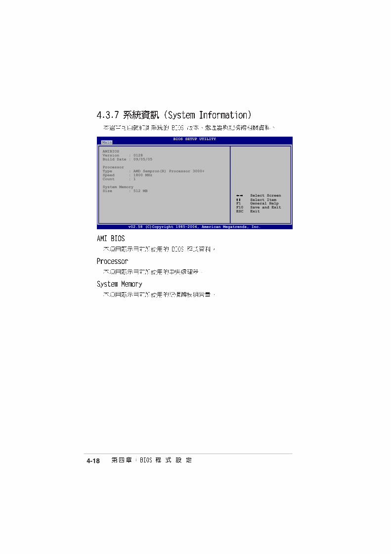
BIOS SETUP UTILITYMain
AMIBIOSVersion : 0128Build Date : 09/05/05
ProcessorType : AMD Sempron(R) Processor 3000+Speed : 1800 MHzCount : 1
System MemorySize : 512 MB

4-19
LAN Cable StatusAMD Cool ‘n’ Quiet ConfigurationJumperFree ConfigurationCPU ConfigurationChipsetOnboard Devices ConfigurationPCI PnPUSB Configuration
POST Check LAN Cable [Disabled]
LAN Cable StatusPair Status Length
1-2 Open 0.0M3-6 Open 0.0M4-5 Open 0.0M7-8 Open 0.0M
1-2 Open N/A3-6 Open N/A4-5 Open N/A7-8 Open N/A
Check LAN cable duringPOST.
4-20
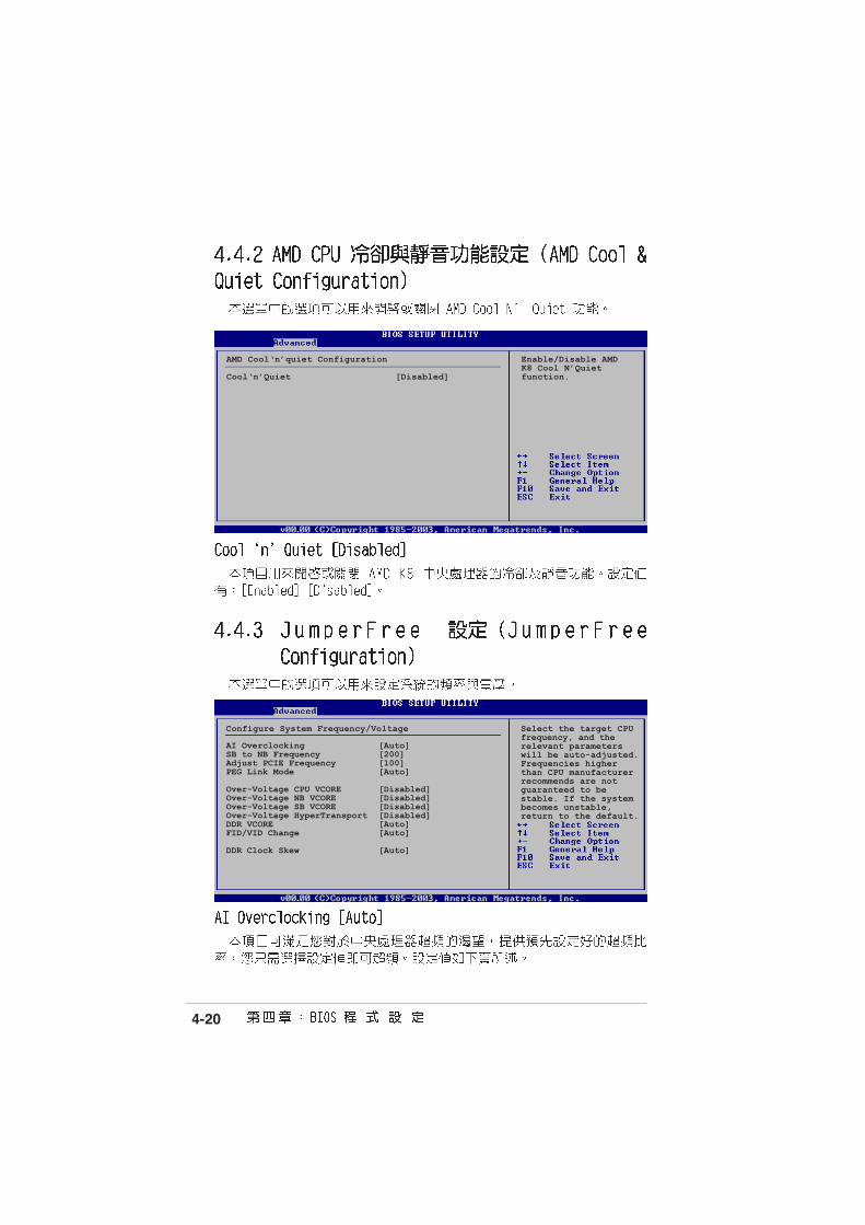
AMD Cool‘n’quiet Configuration Enable/Disable AMDK8 Cool N’Quiet
Cool‘n’Quiet [Disabled] function.
Configure System Frequency/Voltage
AI Overclocking [Auto]SB to NB Frequency [200]Adjust PCIE Frequency [100]PEG Link Mode [Auto]
Over-Voltage CPU VCORE [Disabled]Over-Voltage NB VCORE [Disabled]Over-Voltage SB VCORE [Disabled]Over-Voltage HyperTransport [Disabled]DDR VCORE [Auto]FID/VID Change [Auto]
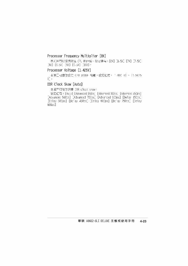
DDR Clock Skew [Auto]
Select the target CPUfrequency, and therelevant parameterswill be auto-adjusted.Frequencies higherthan CPU manufacturerrecommends are notguaranteed to bestable. If the systembecomes unstable,return to the default.

4-21

4-22
4-23
4-24
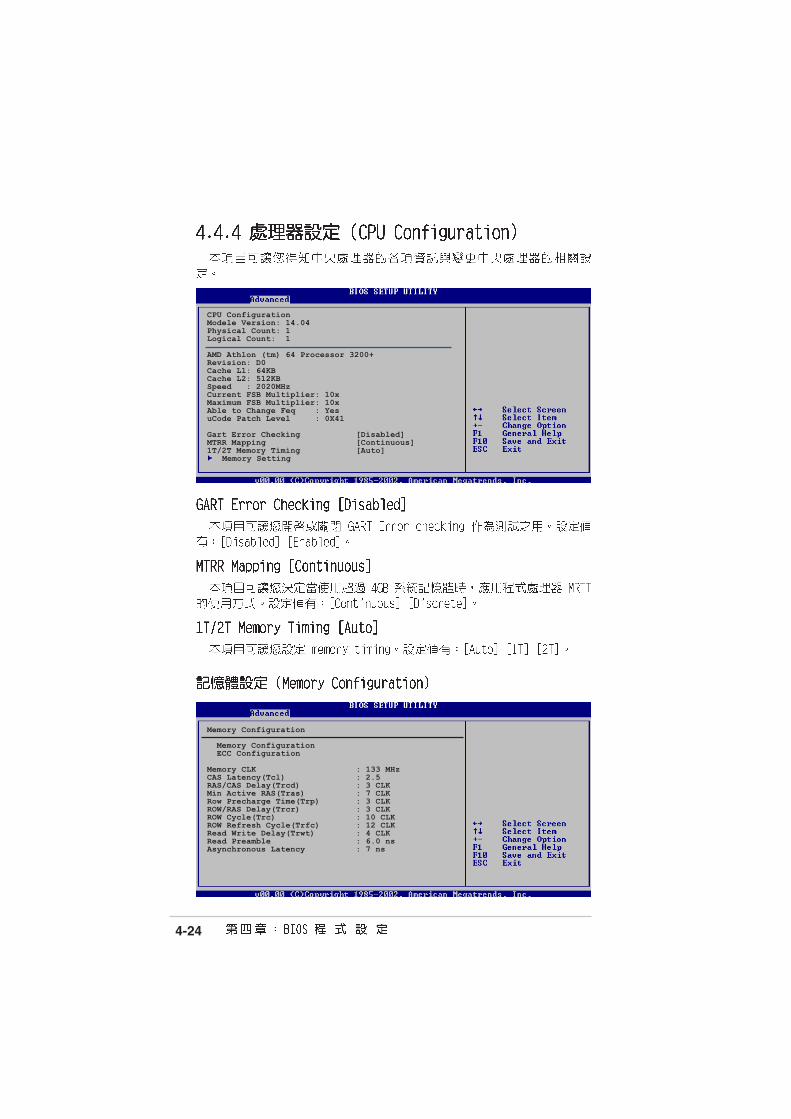
CPU ConfigurationModele Version: 14.04Physical Count: 1Logical Count: 1
AMD Athlon (tm) 64 Processor 3200+Revision: D0Cache L1: 64KBCache L2: 512KBSpeed : 2020MHzCurrent FSB Multiplier: 10xMaximum FSB Multiplier: 10xAble to Change Feq : YesuCode Patch Level : 0X41
Gart Error Checking [Disabled]MTRR Mapping [Continuous]1T/2T Memory Timing [Auto]
Memory Setting
Memory Configuration
Memory Configuration ECC Configuration
Memory CLK : 133 MHzCAS Latency(Tcl) : 2.5RAS/CAS Delay(Trcd) : 3 CLKMin Active RAS(Tras) : 7 CLKRow Precharge Time(Trp) : 3 CLKROW/RAS Delay(Trcr) : 3 CLKROW Cycle(Trc) : 10 CLKROW Refresh Cycle(Trfc) : 12 CLKRead Write Delay(Trwt) : 4 CLKRead Preamble : 6.0 nsAsynchronous Latency : 7 ns
4-25
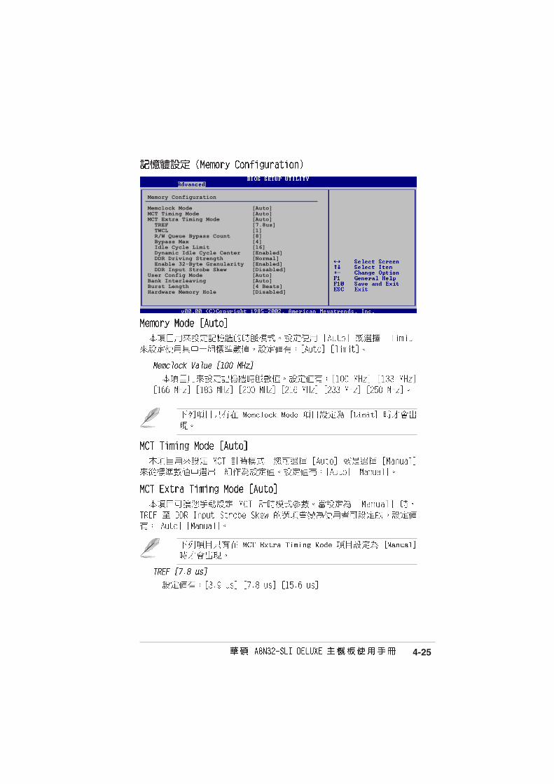
Memory Configuration
Memclock Mode [Auto]MCT Timing Mode [Auto]MCT Extra Timing Mode [Auto] TREF [7.8us] TWCL [1] R/W Queue Bypass Count [8] Bypass Max [4] Idle Cycle Limit [16] Dynamic Idle Cycle Center [Enabled] DDR Driving Strength [Normal] Enable 32-Byte Granularity [Enabled] DDR Input Strobe Skew [Disabled]User Config Mode [Auto]Bank Interleaving [Auto]Burst Length [4 Beats]Hardware Memory Hole [Disabled]

4-26
4-27
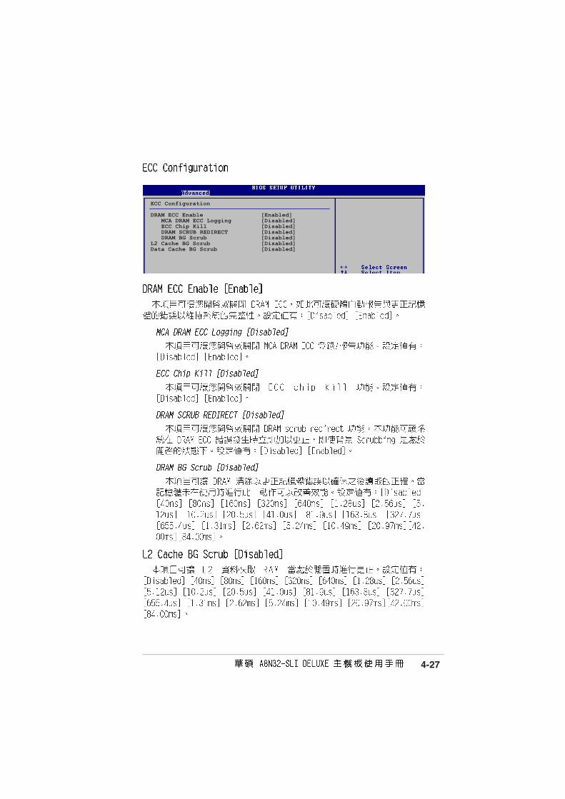
ECC Configuration
DRAM ECC Enable [Enabled]MCA DRAM ECC Logging [Disabled]ECC Chip Kill [Disabled]DRAM SCRUB REDIRECT [Disabled]DRAM BG Scrub [Disabled]
L2 Cache BG Scrub [Disabled]Data Cache BG Scrub [Disabled]

4-28
Select Screen Select Item
+- Change OptionF1 General HelpF10 Save and ExitESC Exit
v02.58 (C)Copyright 1985-2004, American Megatrends, Inc.
BIOS SETUP UTILITYAdvanced
Advanced Chipset Settings
WARNING: Setting wrong values in below settings may cause system to malfunction.
K8 to NB Frequency [Auto]K8 to NB Link Width [Auto]SB to NB Frequency [1000 MHz]SB to NB Link Width [16↓ ↓ ↓ ↓ ↓ 16↑↑↑↑↑]
Primary Graphics Adapter [PciE->PCI->PciE2]
ENABLE: Allowremapping ofoverlapped PCI memoryabove the totalphysical memory.
DISABLE: Do notallows remapping ofmemory.

4-29
Configure ITE8712 Super IO Chipset
Serial Port1 Address [3F8/IRQ4]Parallel Port Address [378]Parallel Port Mode [EPP+ECP] EPP Version [1.9] ECP Mode DMA Channel [DMA3] Parallel Port IRQ [IRQ7]OnBoard Game Port [Disabled]OnBoard MIDI Port [Disabled] MIDI IRQ Select [IRQ5]
1394 [Enabled]Silicon Image Mode [RAID Mode]Onboard\GBE LAN1 [Enabled] Onboard LAN Boot ROM [Disabled]MAC\GBE LAN2 [Auto] Onboard LAN Boot ROM [Disabled]OnBoard AC’97 Audio DEVICE [Enabled]

4-30

4-31
Select Screen Select Item
+- Change OptionF1 General HelpF10 Save and ExitESC Exit
v02.58 (C)Copyright 1985-2004, American Megatrends, Inc.
BIOS SETUP UTILITYAdvanced
Advanced PCI/PnP Settings
WARNING: Setting wrong values in below sections may cause system to malfunction.
Plug And Play O/S [No]PCI Latency Timer [64]Allocate IRQ to PCI VGA [Yes]
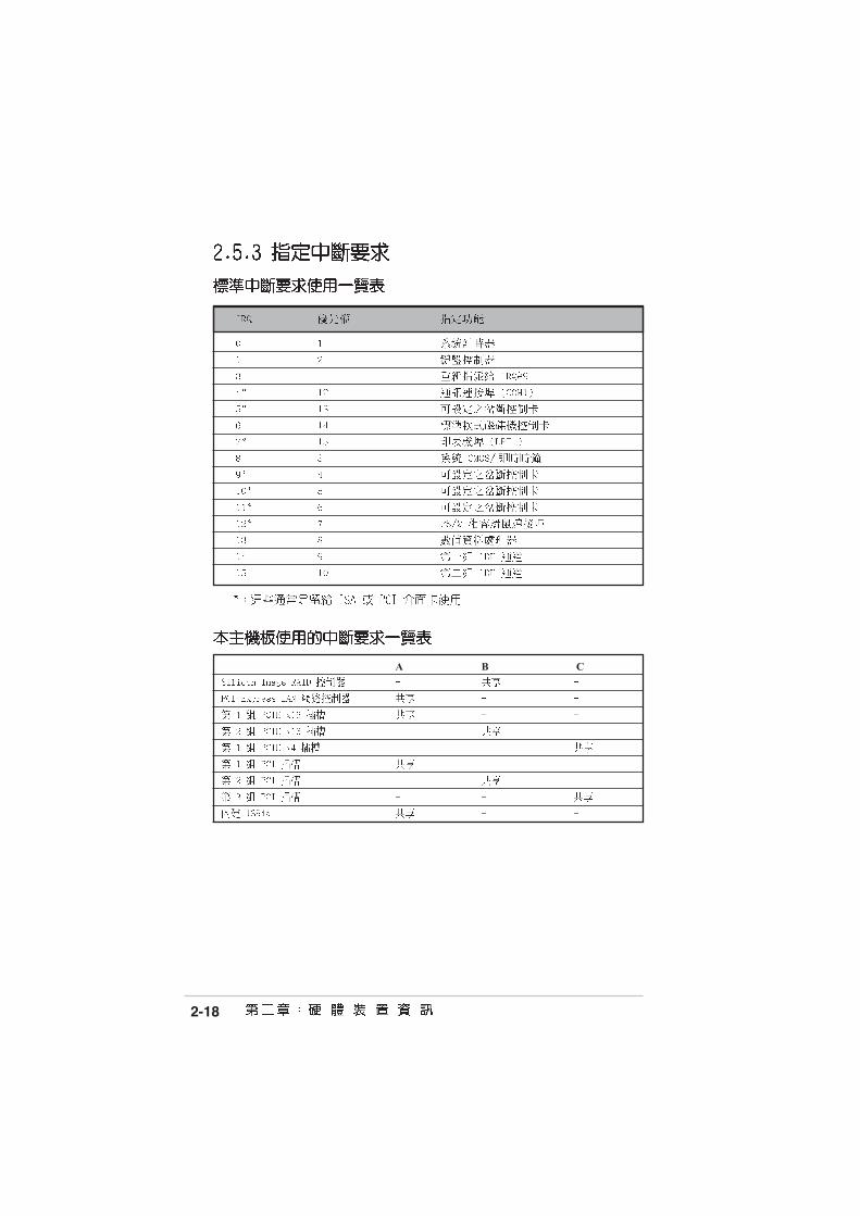
IRQ-3 assigned to [PCI Device]IRQ-4 assigned to [PCI Device]IRQ-5 assigned to [PCI Device]IRQ-7 assigned to [PCI Device]IRQ-9 assigned to [PCI Device]IRQ-10 assigned to [PCI Device]IRQ-11 assigned to [PCI Device]IRQ-14 assigned to [PCI Device]IRQ-15 assigned to [PCI Device]
NO: Lets the BIOSconfigue all thedevices in the system.YES: Lets theoperating systemconfigure Plug andPlay (PnP) devices notrequired for boot ifyour system has a Plugand Play operatingsystem.
4-32
Select Screen Select Item
+- Change OptionF1 General HelpF10 Save and ExitESC Exit
v02.58 (C)Copyright 1985-2004, American Megatrends, Inc.
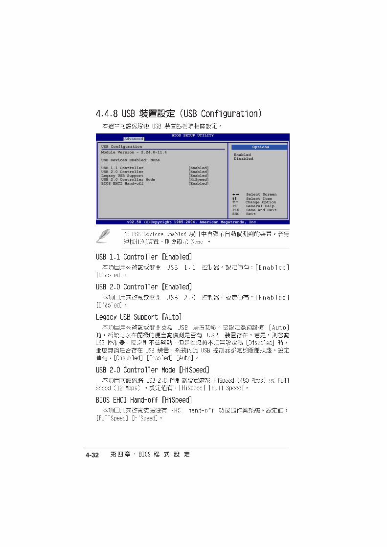
BIOS SETUP UTILITYAdvanced
USB ConfigurationModule Version - 2.24.0-11.4
USB Devices Enabled: None
USB 1.1 Controller [Enabled]USB 2.0 Controller [Enabled]Legacy USB Support [Enabled]USB 2.0 Controller Mode [HiSpeed]BIOS EHCI Hand-off [Enabled]
Options
EnabledDisabled

4-33
Select Screen Select Item
+- Change FieldF1 General HelpF10 Save and ExitESC Exit
v02.58 (C)Copyright 1985-2004, American Megatrends, Inc.
BIOS SETUP UTILITYMain Advanced Power Boot Exit
Suspend Mode [Auto]Repost Video on S3 Resume [No]ACPI APIC Support [Enabled]
APM ConfigurationHardware Monitor

4-34
Select Screen Select Item
+- Change OptionF1 General HelpF10 Save and ExitESC Exit
v02.58 (C)Copyright 1985-2004, American Megatrends, Inc.
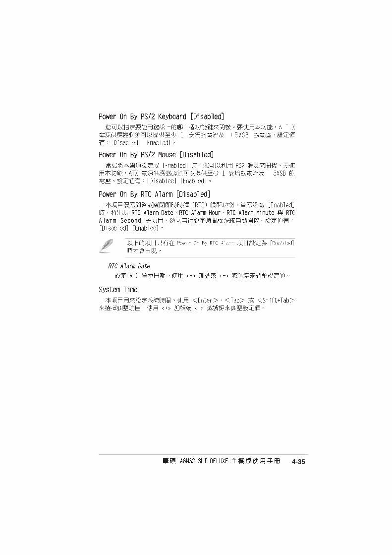
BIOS SETUP UTILITYPower
Restore on AC Power Loss [Power off]Power On By PME# [Disabled]Power On By LAN(MAC) [Disabled]Power On By Ring [Disabled]Power On By PS/2 Keyboard [Disabled]Power On By PS/2 Mouse [Disabled]Power On By RTC Alarm [Disabled]
Go into On/Off orSuspend when Powerbutton is pressed.
4-35

4-36
Select Screen Select Item
+- Change OptionF1 General HelpF10 Save and ExitESC Exit
v02.58 (C)Copyright 1985-2004, American Megatrends, Inc.
BIOS SETUP UTILITYPower
Hardware MonitorCPU Temperature [32.5ºC/90.5ºF]MB Temperature [36.0ºC/96.5ºF]
CPU Fan Speed (RPM) [3813 RPM]Chassis Fan1 Speed (RPM) [N/A]Power Fan Speed (RPM) [N/A]
VCORE Voltage [ 1.320V]3.3V Voltage [ 3.345V]5V Voltage [ 5.094V]12V Voltage [11.880V]
Smart Q-FAN Function [Disabled]
CPU Temperature
4-37
Select Screen Select ItemEnter Go to Sub-screenF1 General HelpF10 Save and ExitESC Exit
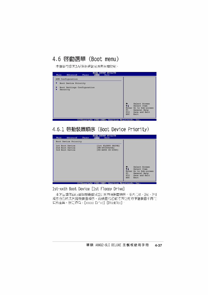
APM Configuration
Boot Device Priority
Boot Settings ConfigurationSecurity
Select Screen Select ItemEnter Go to Sub-screenF1 General HelpF10 Save and ExitESC Exit
Boot Device Priority
1st Boot Device [1st FLOPPY DRIVE]2nd Boot Device [PM-ST330620A]3rd Boot Device [PS-ASUS CD-S360]

4-38
Select Screen Select Item+- Change OptionF1 General HelpF10 Save and ExitESC Exit
Boot Settings Configuration
Quick Boot [Enabled]Full Logo Display [Enabled]AddOn ROM Display Mode [Force BIOS]Bootup Num-Lock [On]PS/2 Mouse Support [Auto]Wait For ‘F1’ If Error [Enabled]Hit ‘DEL’ Message Display [Enabled]Interrupt 19 Capture [Disabled]
Allows BIOS to skipcertain tests whilebooting. This willdecrease the timeneeded to boot thesystem.

4-39
Security Settings
Supervisor Password : Not InstalledUser Password : Not Installed
Change Supervisor PasswordChange User Password
<Enter> to changepassword.<Enter> again todisabled password.

4-40
Security Settings
Supervisor Password : Not InstalledUser Password : Not Installed
Change Supervisor PasswordUser Access Level [Full Access]Change User PasswordClear User PasswordPassword Check [Setup]

4-41
4-42
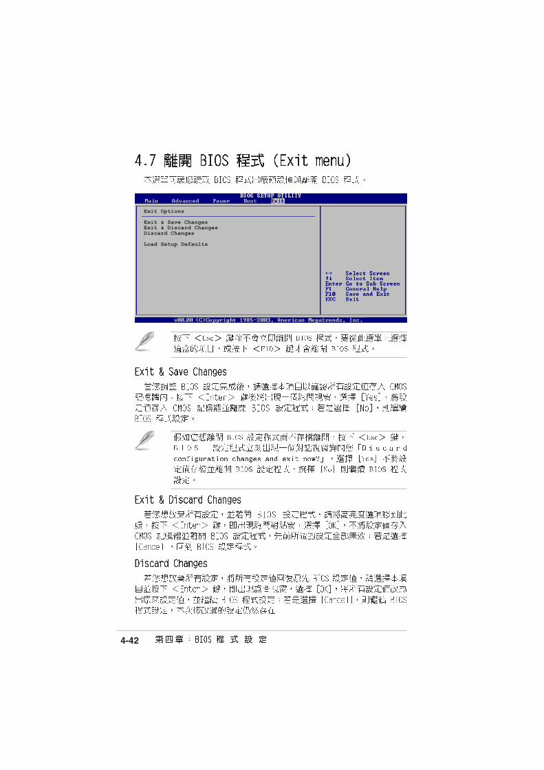
Exit Options
Exit & Save ChangesExit & Discard ChangesDiscard Changes
Load Setup Defaults

4-43

4-44


5-1

5-2

5-3

5-4

5-5
5-6

5-7

5-8

5-9

5-10
5-11
•
•

5-12

5-13

5-14

5-15
5-16
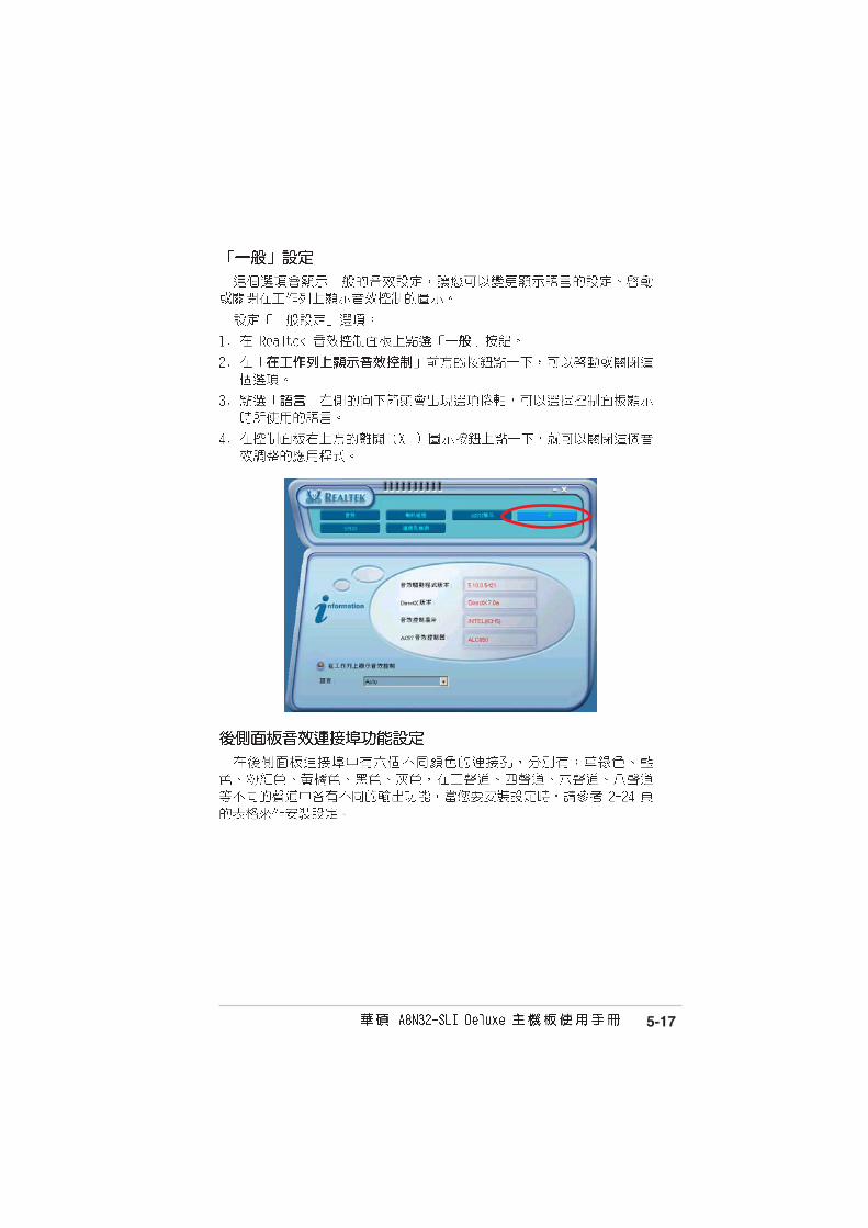
5-17

5-18
®
®
®
®
®
®
®
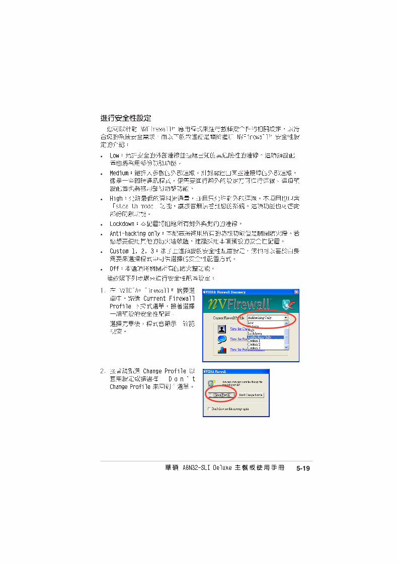
5-19
®
•
•
•
•
•
•
•

5-20
®

5-21

5-22

5-23
5-24

5-25

5-26

5-27
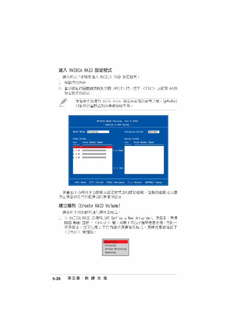
5-28
Mirroring
Striping
Stripe MirroringSpanning
[F6] Back [F7] Finish [TAB] Navigate [↑↓] Select [ENTER] Popup
NVIDIA RAID Utility Oct 5 2004
- Define a New Array -
RAID Mode: Striping Striping Block: Optimal
Free Disks Array Disks
Loc Disk Model Name Loc Disk Model Name
1.0.M XXXXXXXXXXXXXXXXXX
1.1.M XXXXXXXXXXXXXXXXXX [→] Add2.0.M XXXXXXXXXXXXXXXXXX
2.1.M XXXXXXXXXXXXXXXXXX
[←] Del

5-29
Clear disk data?
[Y] YES [N]
8K ↑↑↑↑↑16K32K64K128KOptim↓↓↓↓↓
•
•
•

5-30
[Ctrl-X]Exit [↑↑↑↑↑↓↓↓↓↓]Select [B]Set Boot [N]New Array [ENTER]Detail
NVIDIA RAID Utility Oct 5 2004
- Array List -
Boot Id Status Vendor Array Model Name
No 4 Healthy NVIDIA MIRROR XXX.XXG
[R] Rebuild [D] Delete [C] Clear Disk [ENTER] Return
Array 1 : NVIDIA MIRROR XXX.XXG- Array Detail -
RAID Mode: Mirroring
Striping Width: 1 Striping Block: 64K
Adapt Channel M/S Index Disk Model Name Capacity
2 1 Master 0 XXXXXXXXXXXXXXXXX XXX.XXGB 1 0 Master 1 XXXXXXXXXXXXXXXXX XXX.XXGB
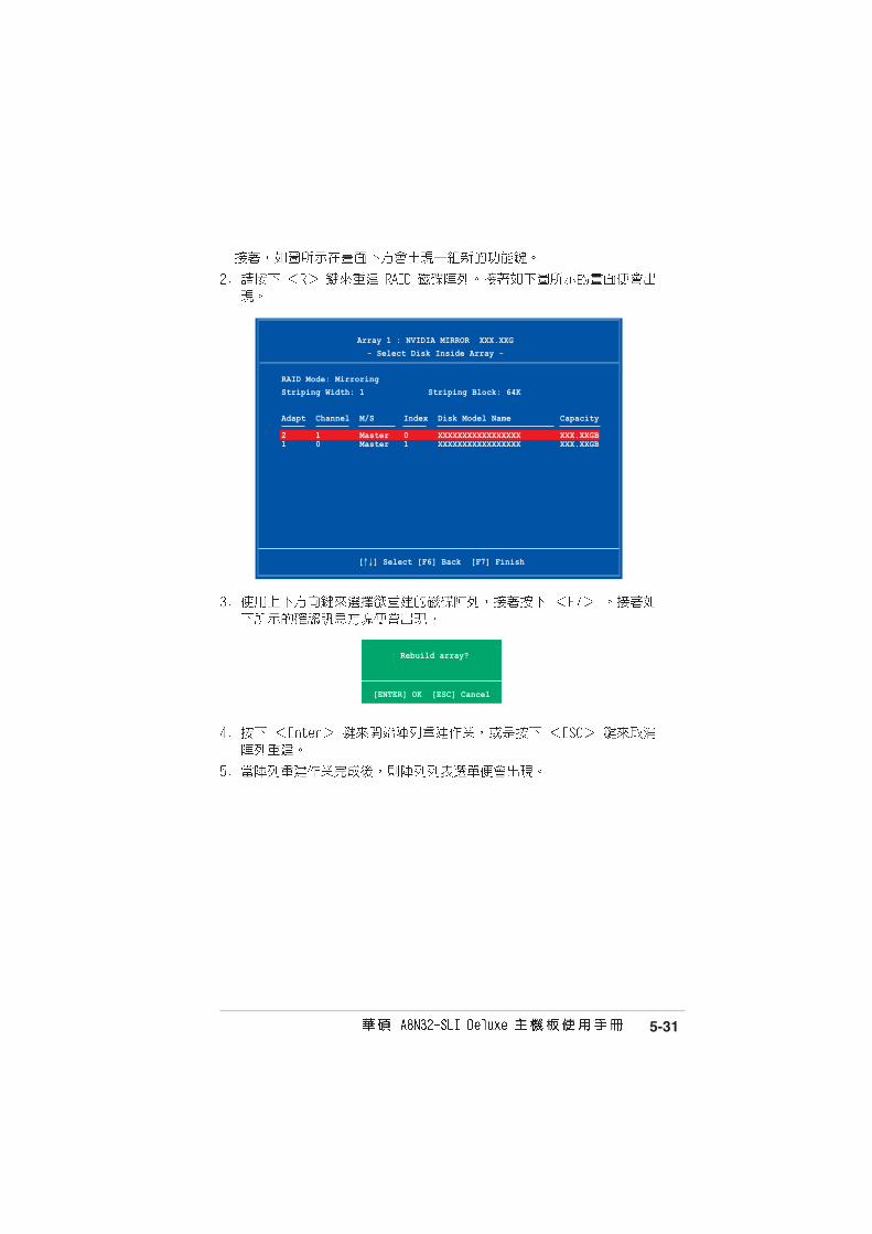
5-31
Rebuild array?
[ENTER] OK [ESC] Cancel
[↑↓] Select [F6] Back [F7] Finish
Array 1 : NVIDIA MIRROR XXX.XXG
- Select Disk Inside Array -
RAID Mode: Mirroring
Striping Width: 1 Striping Block: 64K
Adapt Channel M/S Index Disk Model Name Capacity
2 1 Master 0 XXXXXXXXXXXXXXXXX XXX.XXGB 1 0 Master 1 XXXXXXXXXXXXXXXXX XXX.XXGB

5-32
Delete this array?
[Y] YES [N] No
[R] Rebuild [D] Delete [C] Clear Disk [ENTER] Return
Array 1 : NVIDIA MIRROR XXX.XXG- Array Detail -
RAID Mode: Mirroring
Striping Width: 1 Striping Block: 64K
Adapt Channel M/S Index Disk Model Name Capacity
2 1 Master 0 XXXXXXXXXXXXXXXXX XXX.XXGB 1 0 Master 1 XXXXXXXXXXXXXXXXX XXX.XXGB
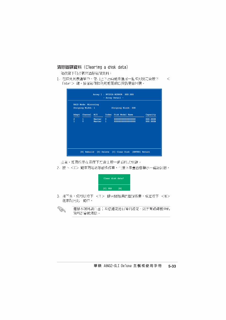
5-33
Clear disk data?
[Y] YES [N]
[R] Rebuild [D] Delete [C] Clear Disk [ENTER] Return
Array 1 : NVIDIA MIRROR XXX.XXG
- Array Detail -
RAID Mode: Mirroring
Striping Width: 1 Striping Block: 64K
Adapt Channel M/S Index Disk Model Name Capacity
2 1 Master 0 XXXXXXXXXXXXXXXXX XXX.XXGB 1 0 Master 1 XXXXXXXXXXXXXXXXX XXX.XXGB

5-34
®

5-35
Create RAID setDelete RAID setRebuild Raid1 setResolve ConflictsLow Level FormatLogical Drive Info
RAID Configuration Utility - Silicon Image Inc. Copyright (C) 2004
↑↑↑↑↑↓↓↓↓↓:Select Menu ESC:Previous Menu Enter:Select Ctrl-E:Exit
MAIN MENU
PHYSICAL DRIVE
0 XXXXXXXXXXX XXXXXXMB1 XXXXXXXXXXX XXXXXXMB2 XXXXXXXXXXX XXXXXXMB3 XXXXXXXXXXX XXXXXXMB
STXXXXXXXXX XXXXXXMBSTXXXXXXXXX XXXXXXMBSTXXXXXXXXX XXXXXXMBSTXXXXXXXXX XXXXXXMB
LOGICAL DRIVE
HELP
Press “Enter” to createRAID set
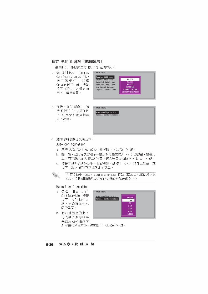
5-36
MAIN MENU
Auto configurationManual configuration chunk
size4K8K16K32K64K128K
MAIN MENU
Auto configurationManual configuration
MAIN MENU
Create RAID setDelete RAID setRebuild Raid1 setResolve ConflictsLow Level FormatLogical Drive Info
RAID0RAID1RAID5RAID10
SPARE DRIVECONCATENATION

5-37
PHYSICAL DRIVE
0 XXXXXXXXXXX XXXXXXMB1 XXXXXXXXXXX XXXXXXMB2 XXXXXXXXXXX XXXXXXMB3 XXXXXXXXXXX XXXXXXMB
MAIN MENU
Auto configurationManual configuration
MAIN MENU
Create RAID setDelete RAID setRebuild Raid1 setResolve ConflictsLow Level FormatLogical Drive Info
RAID0RAID1RAID10SPARE
DRIVE
RAID0RAID1RAID5RAID10
SPARE DRIVECONCATENATION

5-38
PHYSICAL DRIVE
0 XXXXXXXXXXX XXXXXXMB1 XXXXXXXXXXX XXXXXXMB2 XXXXXXXXXXX XXXXXXMB3 XXXXXXXXXXX XXXXXXMB
MAIN MENU
Auto configurationManual configuration
Create with data copyCreate without data copy

5-39
MAIN MENU
Auto configurationManual configuration
online copyoffline copy
5-40
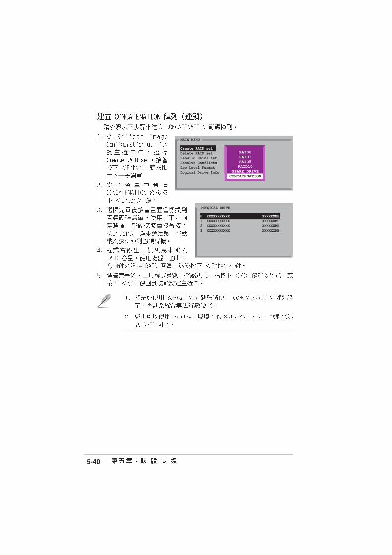
PHYSICAL DRIVE
0 XXXXXXXXXXX XXXXXXMB1 XXXXXXXXXXX XXXXXXMB2 XXXXXXXXXXX XXXXXXMB3 XXXXXXXXXXX XXXXXXMB
MAIN MENU
Create RAID setDelete RAID setRebuild Raid1 setResolve ConflictsLow Level FormatLogical Drive Info
RAID0RAID1RAID10SPARE
DRIVE
RAID0RAID1RAID5RAID10
SPARE DRIVECONCATENATION

5-41


6-1
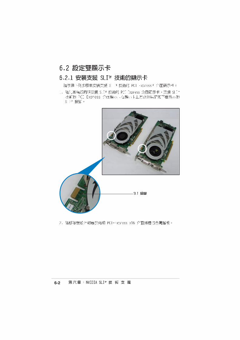
®
®
• ®
•
•
6-2

6-3
6-4
A8N
32-S
LI
®
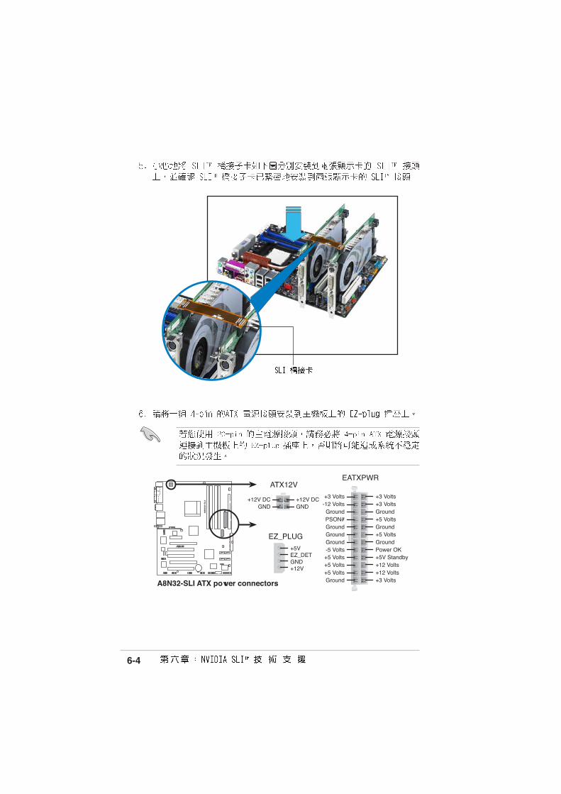
A8N32-SLI ATX power connectors
EATXPWRATX12V
EZ_PLUG
+5VEZ_DETGND+12V
+12V DCGND
+12V DCGND
+3 Volts+3 VoltsGround+5 Volts
+5 VoltsGround
GroundPower OK+5V Standby+12 Volts
-5 Volts
+5 Volts
+3 Volts-12 VoltsGround
GroundGroundPSON#
Ground
+5 Volts
+12 Volts+3 Volts
+5 VoltsGround

6-5

6-6
®
®

6-7
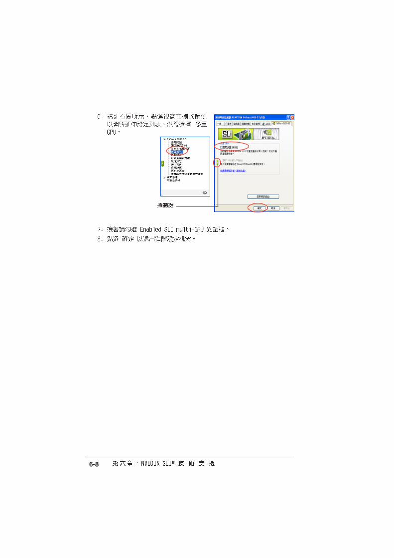
6-8