Embed Size (px)
Citation preview
A Virtual Environment for the Design and Simulated
Construction of Prefabricated Buildings
Norman Murray1, Terrence Fernando1, Ghassan Aouad2
1Centre for Virtual Environments, Business House,
University of Salford, Salford, M5 4WT, U.K. [email protected]
2School of Construction and Property Management, Bridgewater Building,
University of Salford, Salford, M7 9NU, U.K.
Abstract: The construction industry has acknowledged that its current working practices are in
need of substantial improvements in quality and efficiency and has identified that computer modeling
techniques and the use of prefabricated components can help reduce times, costs, and minimise defects
and problems of on-site construction. This paper describes a virtual environment to support the de-
sign and construction processes of buildings from prefabricated components and the simulation of their
construction sequence according to a project schedule. The design environment can import a library of
3D models of prefabricated modules that can be used to interactively design a building. Using Microsoft
Project, the construction schedule of the designed building can be altered, with this information feeding
back to the construction simulation environment. Within this environment the order of construction
can be visualised using virtual machines. Novel aspects of the system are that it provides a single 3D
environment where the user can construct their design with minimal user interaction through automatic
constraint recognition and view the real-time simulation of the construction process within the environ-
ment. This takes this area of research a step forward from other systems that only allow the planner to
view the construction at certain stages, and do not provide an animated view of the construction process.
It is intended that these models and simulations will be used to represent the dynamics of the Future-
Home construction site enhancing current construction practices that use flat 2D plans and Gantt charts.
Keywords: modular construction, prefabricated components, virtual construction environment.
CORE Metadata, citation and similar papers at core.ac.uk
Provided by University of Salford Institutional Repository
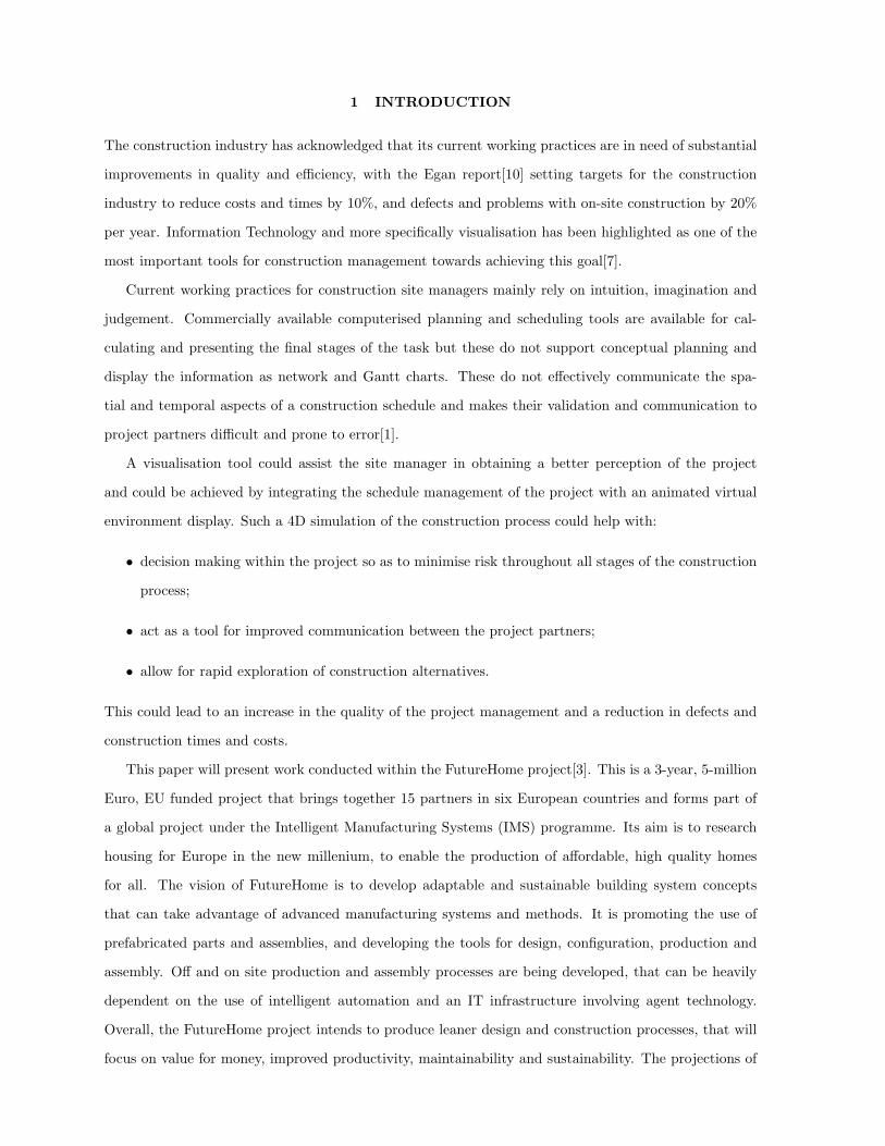
1 INTRODUCTION
The construction industry has acknowledged that its current working practices are in need of substantial
improvements in quality and efficiency, with the Egan report[10] setting targets for the construction
industry to reduce costs and times by 10%, and defects and problems with on-site construction by 20%
per year. Information Technology and more specifically visualisation has been highlighted as one of the
most important tools for construction management towards achieving this goal[7].
Current working practices for construction site managers mainly rely on intuition, imagination and
judgement. Commercially available computerised planning and scheduling tools are available for cal-
culating and presenting the final stages of the task but these do not support conceptual planning and
display the information as network and Gantt charts. These do not effectively communicate the spa-
tial and temporal aspects of a construction schedule and makes their validation and communication to
project partners difficult and prone to error[1].
A visualisation tool could assist the site manager in obtaining a better perception of the project
and could be achieved by integrating the schedule management of the project with an animated virtual
environment display. Such a 4D simulation of the construction process could help with:
• decision making within the project so as to minimise risk throughout all stages of the construction
process;
• act as a tool for improved communication between the project partners;
• allow for rapid exploration of construction alternatives.
This could lead to an increase in the quality of the project management and a reduction in defects and
construction times and costs.
This paper will present work conducted within the FutureHome project[3]. This is a 3-year, 5-million
Euro, EU funded project that brings together 15 partners in six European countries and forms part of
a global project under the Intelligent Manufacturing Systems (IMS) programme. Its aim is to research
housing for Europe in the new millenium, to enable the production of affordable, high quality homes
for all. The vision of FutureHome is to develop adaptable and sustainable building system concepts
that can take advantage of advanced manufacturing systems and methods. It is promoting the use of
prefabricated parts and assemblies, and developing the tools for design, configuration, production and
assembly. Off and on site production and assembly processes are being developed, that can be heavily
dependent on the use of intelligent automation and an IT infrastructure involving agent technology.
Overall, the FutureHome project intends to produce leaner design and construction processes, that will
focus on value for money, improved productivity, maintainability and sustainability. The projections of
benefits from the project are estimated at 30% in the cost of construction, 35% in construction time and
a reduction of 60% in the number of defects.
As part of this research a virtual design, construction and scheduling environment has been imple-
mented that allows a model of a house to be constructed from a library of prefabricated components
defined within the FutureHome project. The construction of the model requires minimal user interaction
as the environment supports automatic constraint recognition between the components, so that as the
user is constructing their model the system automatically detects whether the components the user is
manipulating can be linked. An object database has been designed that holds the types of modules
that are used in the building and relevant information pertaining to that component, such as price, size,
construction methods, etc. As the user constructs the building, the construction information is also
stored within the object database along with the order of construction and any dependencies between
the tasks. As well as being able to review the building that they have constructed from within the virtual
environment, the construction order of 3D model can be replayed to provide an animated 4D model of
the construction process combined with virtual machines, such as a crane, to simulate the construction
process. Using Microsoft Project the construction schedule of the project can be altered and fed back
into the virtual construction environment to explore alternative construction scheduling. The database
also holds information relating to the construction site, such as stock, resources and delivery information.
The paper is organised as follows: Section 2 discusses related work in the areas of 4D construction
systems and virtual environments. Section 3 describes the system architecture that is required for the
development of a virtual environment to support the design and construction simulation. Section 4
describes the implemented system in use using a conceptual prototype defined within the FutureHome
project as a developmental case study showing: how the design is created; the construction simulation
environment; and how the schedule is altered. Finally, Section 5 reviews the system.
2 RELATED RESEARCH WORK
Virtual Environments can offer the area of computer aided design many valuable extensions as it can
provide a more intuitive means of communication with the computer. Much of the work involving
virtual environments and construction has been related to architectural walkthroughs. These can allow
for such factors as aesthetics, e.g. lighting, acoustics and internal layout, and also the spatial location
of the building and its impact on the surrounding environment to be evaluated, e.g. see [16, 21, 24].
Such visualisations tend not to be dynamic: the user can navigate through the environments but has
limited or no interaction with the artifacts within the environment. Furthermore, the models of the
buildings themselves will only be realistic in their appearance, they will not be realistic as far as the
actual composition of components is concerned. These examples only deal with the final stage of the
process, visualising the completed building, whereas the construction planning and scheduling tasks deal
with the entire construction process from its conception until the completion of the construction.
Within the area of design in virtual environments much work has been done allowing users to compose
scenes within virtual environments, such as 3DM [5], and JDCAD [19] which tackled many of the issues
involved in the interactive creation of 3D objects. Problems with such systems are the absence of
constraints when interacting with virtual objects. Users are restricted to gross interactions and are
unable to perform precise object manipulation[20]. Systems that support constraint based assembly of
components provide the user with the support required to align components automatically, removing the
need for the user to align components precisely. There have been several research efforts to investigate
the development of assembly simulation environments. For example, Connachar et al. [6] describes a
system called VADE (Virtual Assembly Design Environment) interfaced with the Pro/Engineer modelling
environment. A CAD database is connected to the Open Inventor API through Pro/Engineer Pro
Develop Toolkit. In this system, direct interaction is supported through a CyberGlove. Fernando et al.
[13], Fa et al. [12], Munlin [22], and Thomson et al. [27], have developed an Interactive Constraint Based
Assembly Modelling (ICBAM) environment to bring physical realism to the assembly simulation arena.
Fernando et al. [13] describes the methods developed for allowable motion and constraint recognition
within the system. Automatic recognition of constraints such as ’against’, ’coincident’, ’tangential’, and
’concentric’ are supported in their system. By reading constraint relationships stored in a Relationship
Graph, degrees of freedom can be computed so that the system can determine the allowable motions for
a given assembly part. The VR environment is implemented using the IRIS Inventor graphical toolkit.
The system described by Fernando et al. [13] reported some shortcomings. They include, inability to
support constraint propagation from child object to parent when the child object is being manipulated
in the assembly, and the absence of a standard data translator for CAD data import into the virtual
environment.
Research has been conducted in the utilisation of computer graphics in construction planning and
scheduling. For a recent survey see[29] (this is further extended within [28]). Some early systems generate
and simulate the process of construction within CAD environments rather than use VR technology,
e.g.[17, 18]. Op den Bosch & Baker[9] provide the user with construction equipment to construct their
building. This they argue leads the user to focus on the engineering issues related to the construction of
the building, rather than issues regarding the creation of the model within a computer environment.
Other researchers have created environments that allow the user to view the model at various stages of
completion, e.g.[1, 15]. Schweglerl et al.[25] used an interactive 4D prototype tool that allowed planners
to work with the 4D model at several levels of detail and change the 3D model and schedule in the
4D environment. OSCON[2] allows users to construct buildings from parts such as doors, windows,
slabs, etc. OSCON incorporates a time and cost model within its architecture and the models that
are constructed can be viewed in VRML and queries regarding such variables as cost, visualising the
information on the 3D model, or time, showing the state of the construction at any specified time can
be performed. OSCON provides further project management capabilities over its 3D visualisations and
query facilities, for full details see[2].
The work reported here aims to supply the site managers with visualisation tools so that they are
better equipped to plan the construction process as their current activities rely on intuition, imagination
and judgement. These tools allow for 3D visualisations of the construction process and could aid site
planners organise their activities to varying degrees. To date, the OSCON project has gone furtherest in
providing the user with a tool where a building can be constructed from components located in an object
database including task information, costs, etc., and providing schedule management, cost estimation,
and a 3D view of the construction process at various stages. In the following sections, the system built
for the FutureHome project will be reviewed.
3 SYSTEM DESIGN
In this section, the design of the system and the reasoning behind it will be detailed. The initial high
level requirements of system are to:
• be able to create the building design from a set of components or objects that compose the actual
building;
• view the construction simulation in real-time in a 3D environment;
• examine the project schedule and allow it to be manipulated with changes being shown in the
construction simulation environment;
The system architecture builds upon the authors’ previous research on constraint-based modeling,
virtual environment interface design, product and object databases, and other relevant state-of-the-art
technologies, see Figure 1. To satisfy the requirements, the four main components developed were:
• the virtual environment—for importing the CAD models of the modules and for display and navi-
gation through the environment;
• automatic constraint recognition—this includes a constraint manager for defining how each of
the modules are connected in relation to one another and maintaining allowable movements and
relations between each of the components, and a collision detection module for detecting collisions
between modules so allowing the constraints to be generated automatically;
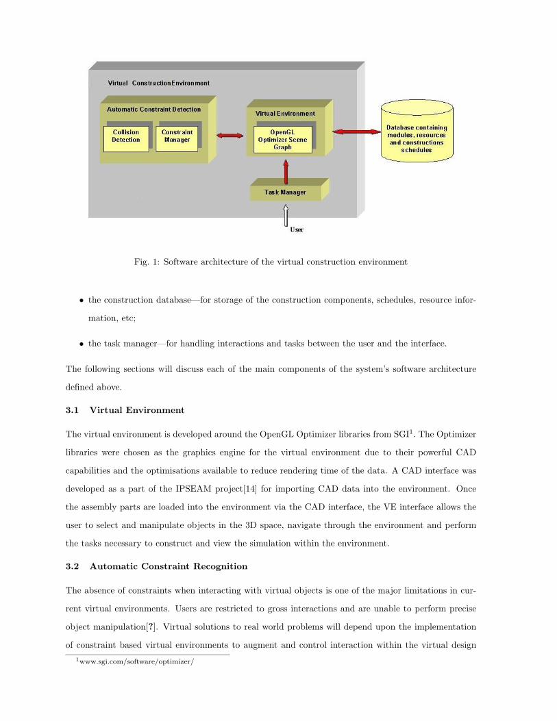
Fig. 1: Software architecture of the virtual construction environment
• the construction database—for storage of the construction components, schedules, resource infor-
mation, etc;
• the task manager—for handling interactions and tasks between the user and the interface.
The following sections will discuss each of the main components of the system’s software architecture
defined above.
3.1 Virtual Environment
The virtual environment is developed around the OpenGL Optimizer libraries from SGI1. The Optimizer
libraries were chosen as the graphics engine for the virtual environment due to their powerful CAD
capabilities and the optimisations available to reduce rendering time of the data. A CAD interface was
developed as a part of the IPSEAM project[14] for importing CAD data into the environment. Once
the assembly parts are loaded into the environment via the CAD interface, the VE interface allows the
user to select and manipulate objects in the 3D space, navigate through the environment and perform
the tasks necessary to construct and view the simulation within the environment.
3.2 Automatic Constraint Recognition
The absence of constraints when interacting with virtual objects is one of the major limitations in cur-
rent virtual environments. Users are restricted to gross interactions and are unable to perform precise
object manipulation[?]. Virtual solutions to real world problems will depend upon the implementation
of constraint based virtual environments to augment and control interaction within the virtual design1www.sgi.com/software/optimizer/
environment. Systems that support constraint based assembly of components provide the user with the
support required to align components automatically, removing the need for the user to align compo-
nents precisely. The constraint manager, within the automatic constraint recognition module supports
constraint-based interaction between the components of the building to model their assembly and dis-
assembly. The assembly process consists of a succession of tasks, each of which consists of joining
components to form the final assembly. Parts are considered joined when the necessary contacts and
alignments between parts have been established. These contacts and alignments are referred to as as-
sembly relationships, which are described in terms of geometric constraints and are solved using the
Geometric Constructive approach[13]. For further information on constraint-based modeling see[14].
Automatic constraint recognition removes the costly requirement of having the user specify each
constraint individually and relies on the system to detect the constraints as the user manipulates the
components. Bier[4] proposed a 3D snapping technique for building 3D models. These concepts were
further extended by Fernando[13] to support interactive assembly modeling. In this construction envi-
ronment, constraints are recognised between geometric elements when the assembly parts come together
and full 3D automatic constraint detection is supported.
The automatic constraint recognition component calculates whether the two components that are in
collision can have a constraint placed on them. If the user is happy with the placement of the component,
the system aligns the components precisely together according to the surfaces of each of the components.
Users do not need to align objects precisely, the system automatically aligns the objects for them.
With the collision detection and automatic constraint recognition components in place the process
of constructing a building within the virtual design environment is greatly simplified as the user only
needs to move components towards one another and the system highlights the surfaces that are to be
aligned and automatically aligns the objects precisely with each other when the user is satisfied with
their placement. This greatly aids the ability to construct 3D models from their constituent components
and further allows the ability of the models to behave realistically, such as doors rotating on hinges and
the opening of windows. Wimalaratne et al.[30] defines the constraint based system in this project.
3.3 Construction Database
The construction database manages all the information relating to a construction project. The database
stores information on each of the building elements that are available to the user for construction. As
the user selects these elements and constructs the building, the components used and the order and
form of the construction is also stored within the database. The database also stores information on
construction sites, their stock and resources, and deliveries to the sites.
Figure 2 gives an overview of the main elements that compose the object database schema to store

Fig. 2: Simplified view of the object database design and construction schema
the design and its construction schedule. On the left of the figure, a design can be seen to be composed of
components and the constraints that are associated with these components. These objects in themselves
are enough to describe a building but they do not define the order of construction, site data, delivery
times, etc. The right of Figure 2 defines the work plan associated with the design. The work plan is
composed of work tasks that can be broken down either into further work tasks or specific work elements.
There are various types of work element that can be performed such as construction tasks, delivery tasks,
etc. Each of the work elements can also have a set of dependencies or dependents, or a specific starting
time, thus defining the project schedule.
Using this information the building can be reconstructed within the virtual environment from its
constituent modules according to the construction order and its dependencies and also according to
deliveries and stocks at the construction site.
3.4 Task Manager
The task manager manages the interface between the user and the system. Current interactive software
systems can be hard to learn and baffling to the users even with their visual interfaces. One of the
major problems is because the underlying software system has no concept of what the user is trying
to achieve with the system, i.e. it has no internal task knowledge. The user of the system is trying to
complete a task, e.g. to construct a building. This in turn may be decomposed into subtasks such as
joining components together. These are the tasks that the user is trying to complete but the system has
no internal concept of these tasks. If these tasks could be built into the system then this could provide

many benefits to both the end user and the programmer of the software system.
For the end user, a system with built in knowledge of the tasks they are trying to achieve can provide
certain advantages such as context sensitive help while the user is performing their task. This makes
the interface easier to learn as the user can query the system as to its current state, the tasks that are
currently viable and how the user should proceed during a task, and could prove to be less distracting
than having to refer to either printed or online manuals. For the programmer of the software system
the task manager offers the benefits of rapid task prototyping as the specification of task order is easily
altered. Also, unlike event based systems where the programmer has to examine the code to identify the
order of tasks within the system, the task networks can easily be visualised as they are explicitly defined
within the program. For more information on the task manager see[23].
4 SYSTEM IMPLEMENTATION
In this section the system will be described using some of the demonstrator modules and houses that
have been developed within the FutureHome project. The environment will be described by examining:
• the basic virtual environment and interaction within it (Section 4.1);
• the building design process (Section 4.2);
• specification and alteration of the construction schedule (Section 4.3);
• the construction simulation environment (Section 4.4).
4.1 The Virtual Environment and Interaction
The virtual environment was designed so that all interaction takes place within a 3 dimensional domain,
that is, the environment makes no use of ’standard windows’ menus, toolbars, etc, thus making the inter-
face a true virtual environment. Classical user interfaces based on 2D input devices and 2D metaphors
are inadequate for applications that require users to carry out complex 3D tasks. In particular the low-
bandwidth communication between the 2D user interface and the application, together with the inherent
limitations of the 2D mouse for interactive 3D motion specification, make it extremely difficult for users
to perform their work with simple and intuitive actions. Much research has been conducted within the
area of 3D interaction and 3D metaphors but this work is still very much research based and no standard
3D-interaction toolkit currently exists. It was therefore required that all forms of interaction, tools and
widgets within the environment would need to be designed and implemented for the environment. This
will facilitate and ease the transfer of the software from the Windows PC based environment that it
currently runs on, to a high-end Silicon Graphics environment utilising large screen display technology,

(a) A completed building in the environment (b) The SPACE MOUSE with its 6DOF movement
capabilities
Fig. 3: The virtual environment and its interaction hardware
such as the ReaCTor (a CAVE style display), Reality Rooms and V-Desk displays that are available
within the centre[8].
Figure 3(a) gives a view of an example building constructed within the virtual environment. Due
to the limitations of the 2D mouse for accurately and quickly navigating in a virtual environment an
alternative input devices was utilised. In Figure 3(b), we can see the LogiCad3D SPACE MOUSE. Slight
finger pressure on the cap of the SPACE MOUSE can control an object in the virtual environment with
up to 6 degrees of freedom (X, Y, Z, roll, pitch, and yaw movement) simultaneously. The SPACE MOUSE
can also be used to navigate through the virtual design environment, and has nine programmable buttons
that can be used for control within the environment.
The design environment consists of a simple grid laid out along the X and Z planes (the ground) to
define the world. The user is able to navigate about the 3D environment using the SPACE MOUSE and
with the buttons on the SPACE MOUSE is able to bring up menus and make selections from these menus
to add models to the scene, construct buildings, store their designs and replay construction scenarios.
4.2 Building Design
Within the building design environment the user can navigate freely through the 3D environment to
view the components and the building; select components within the environment and apply rotations
and translations to these; and construct a building by bringing the components together. The system
automatically detects how components can be linked together and so eases the task of design construction
within the environment.
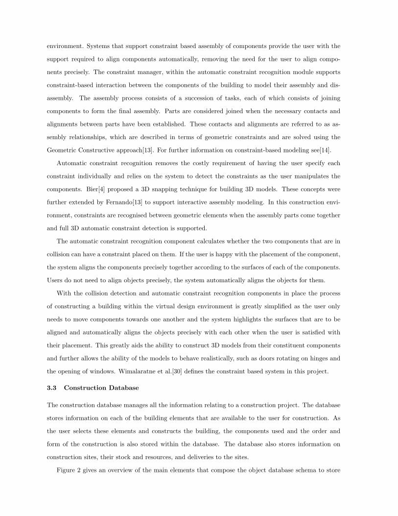
(a) Selection of the components is via a rotating tree
menu
(b) Component selected to be added to the environ-
ment
Fig. 4: Selecting a component
Currently the user can either begin constructing a building from the empty environment or can load
a partially constructed building into the environment and continue construction on that model. From
a menu the user can select a component to add to the building. Figure 4(a) shows the top level of the
rotating menu that depicts the initial breakdown off the module types. The modules are organised as a
tree-like structure with module types having either instances of the type or more specific type descriptors
hanging off each type. The user can rotate the menu with the SPACE MOUSE and also select the module
type which is shown foremost on the screen. This will bring them down the tree menu to the next level
which will display further module types and/or specific modules for selection. When a module is selected
the user can then move that module to where they wish to add it to their current building. Figure 4(b)
shows a service module that has been selected and is about to be added to the current building. The
modules shown within the virtual environment are currently under development within the FutureHome
project. The modules shown have been designed to give an early overview of the concepts that are being
investigated within FutureHome and these will be further developed and envisioned by the FutureHome
project partners.
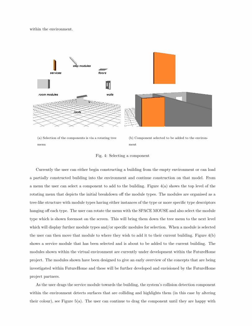
As the user drags the service module towards the building, the system’s collision detection component
within the environment detects surfaces that are colliding and highlights them (in this case by altering
their colour), see Figure 5(a). The user can continue to drag the component until they are happy with
the alignment. The user does not have to align the parts exactly—the system automatically detects
which surfaces can be mated together and aligns each of the components exactly for the user. The user
releases the part when they are happy with their alignment (shown in Figure 5(a)). When the component
is released, the system aligns the parts exactly as shown in Figure 5(b). This is performed using the
constraint manager within the virtual environment that aids the user in aligning parts exactly within
the environment and maintains the relationships between each of the modules and their construction
order (the constraint manager is defined in Section 3.2). As each component is added to the building,
information on the component, its placement, etc are stored within the object database.
(a) Collision between the selected component and
other components within the environment are high-
lighted
(b) The component is released and constrained ap-
propriately
Fig. 5: Example of constraning/constructing a component
Using this approach and with the import of additional 3D models of the modules the building can
be constructed. Figure 3(a) shows the external view of a building modeled using the virtual design
environment from the modules.
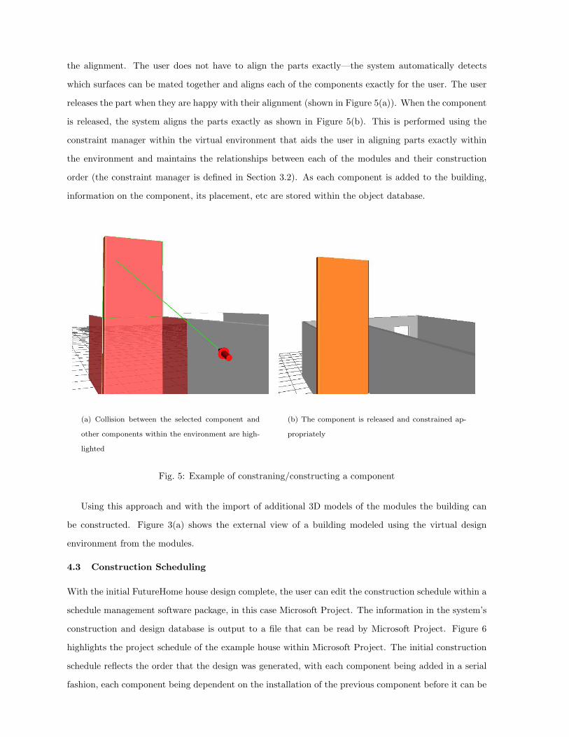
4.3 Construction Scheduling
With the initial FutureHome house design complete, the user can edit the construction schedule within a
schedule management software package, in this case Microsoft Project. The information in the system’s
construction and design database is output to a file that can be read by Microsoft Project. Figure 6
highlights the project schedule of the example house within Microsoft Project. The initial construction
schedule reflects the order that the design was generated, with each component being added in a serial
fashion, each component being dependent on the installation of the previous component before it can be
added to the building.
Fig. 6: A section of the project schedule as viewed in Microsoft Project
Within Microsoft Project, the logic of the construction plan can be altered, e.g. the breakdown of
tasks, dependencies, ordering, etc. Currently it is the constrution planners responsibility to define the
location of plant on the construction site and the definition of exact task times. In the future the system
will incorporate automatic site layout specification software to aid the construction planner in defining
the layout of temporary structures and defining working spaces. This software is currently under de-
velopment within the centre[26]. The construction environment currently supports the typical temporal
sequence relationships (finish-start, start-start, finish-finish and start-finish) between activities and lag
or lead times for the activities. When the construction planner is satisfied with the new construction
schedule, the information can be saved and fed into the construction environment’s database to up-
date the construction schedule. The new construction schedule can then be visualised and animated, as
described in the following section.
4.4 Construction Simulation
With the complete building, the virtual environment can replay the construction process of the building
using the knowledge of the components and their order of construction to provide a 4D animated model
of the construction of the building. The environment supports the replay of any number of simultaneous
tasks up to the amount of available machinery on site. Where an item of plant attempts to be used more
than once at the same time, the system flags an error to the user.
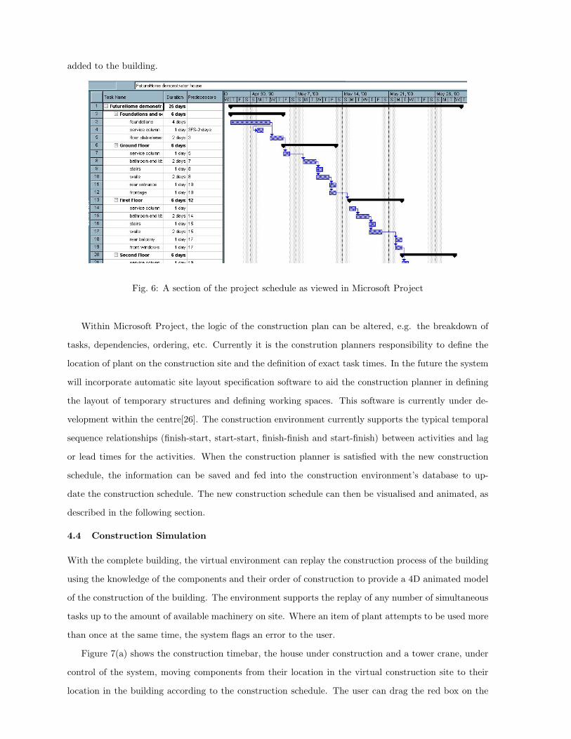
Figure 7(a) shows the construction timebar, the house under construction and a tower crane, under
control of the system, moving components from their location in the virtual construction site to their
location in the building according to the construction schedule. The user can drag the red box on the

(a) The crane in the construction simulation envi-
ronment in action
(b) A component and some details viewed within the
construction environment
Fig. 7: The construction simulation environment
timebar widget to move construction either forwards or backwards in time. As the user drags this bar,
the animation of the tower crane would cease with only the building appearing or disappearing to speed
up processing to the newly selected time.
Planning staff would normally use the 2D working drawings to generate a site layout and working
schedule for the construction process of the prefabricated components. Such a task can rely heavily on
the intuition, imagination and judgement of the planner as current tools fail to offer the planner realistic
visualisations of the schedules. The planning staff have to visualise the spatial relationships in abstract
terms as the plans cannot reflect the construction process of each of the individual components due to
its static nature. The 3D model of the building shown here, integrated with timing parameters so that
the construction process and the on-site layout can be simulated over time goes a step towards solving
this problem, and can be used to assess the placement of plant machinery such as cranes. This could
also be used to test the order of construction of the building so that construction of specific walls or
roofs would not hinder further construction in the vicinity at a later date. Such issues aren’t typically
assessed until the construction process has begun which can lead to costly problems on-site.
Within the construction environment the user also has access to component information via the
construction database. A user can select a component within the design and obtain details on the
component such as cost, dimensions, date of installation, etc. Figure 7(b) shows a component that has
been selected by the user, highlighting some of its attributes.
The environment was developed in association with the construction partners of the FutureHome
project for initial design and implementation tests. Further testing of the of the usability of the en-
vironment will be conducted towards the end of the project in conjunction with the actual building
components that are being designed within FutureHome.
In this section it has been shown how the user can construct a building within the environment
from a database of prefabricated components, edit the construction schedule and view the construction
simulation.
5 CONCLUSIONS
This report discussed the development of a virtual construction environment to allow prefabricated
building components to be used to model the construction processes. Within the environment the user
can:
• create the building design from a set of prefabricated components as defined within FutureHome.
Within the virtual environment the user can construct a geometrically constrained building from
a library of components using collision detection and automatic constraint recognition. OSCON
also allows for construction from components although this is performed in a CAD environment
and does not support automatic constraint recognition.
• examine the project schedule within Microsoft Project and allow it to be manipulated with changes
being fed back to the construction simulation environment. This provides functionality that is
similar to OSCON.
• view the construction simulation in real-time in a 3D environment. Allows the construction to
be simulated in real-time animation with virtual machines rather than showing certain stages of
construction as in OSCON and other systems.
Novel aspects of the system are that it provides a single 3D environment where the user can construct
their design with minimal user interaction through automatic constraint recognition that eases the task of
aligning components within the 3D environment, and view the real-time simulation of the construction
within the environment. This takes the work a step forward from other systems that only allow the
planner to view construction at certain stages and do not provide an animated view of the construction
process.
Currently the construction planner alters the logic of the construction schedule via a Gantt chart
within Microsoft Project. This separates the work items within the Gantt chart from their visualisation
within the virtual environment. Further development will include an interface within the construction
environment to allow for the construction planner to alter the logic of the plan within the virtual
environment, and so be able to see their altered plan in operation immediately. Further development of
the interface will allow it to be used in a CAVE and Reality Wall type environments that are housed
within the Centre for Virtual Environments.
It is envisaged that the models generated could be used throughout the construction and maintenance
of the building as a reference tool to aid the construction site planners. These 4D models will provide
more effective communication of the FutureHome construction process, making clear the sequence of
construction and the utilisation of intelligent automation and site sensors at the construction site to
establish the constructability of proposed systems. A by-product of the use of virtual reality is that
the completed model can be examined in the future when the building owners need to perform some
maintenance or replacement. Instead of handing over as-built drawings, FutureHome will provide an
adaptable 3D model of the building. Within the FutureHome project, an actual demonstrator of the
components and construction of the house will be tested through the construction of a full scale demon-
strator. Using this full scale demonstration of FutureHome, the system will be tested with an actual test
case to evaluate the capabilities, advantages and limitations of the system.
There is still much work to be conducted in this area. Schweglerl et al.[25] identify the advantages
that could be gained from this area of research and identifies many areas that can benefit from the use
of 3D and 4D models throughout the life-cycle of a project. The research presented in this paper aims
to increase the construction company’s competitiveness through the integration of technology, a priority
highlighted in a recent EU paper[11].
ACKNOWLEDGEMENTS
The constraint based development manager is being developed as part of an EPSRC funded project.
The development of the virtual environment for simulating building construction is being developed
as part of the FutureHome project supported by the EU Brite/Euram award (project ER4-29671), see
http://www.cv.ic.ac.uk/futurehome/ for more information.
REFERENCES
[1] T. Adjei-Kumi, A. Retik, and A. Shapira. Integrating on-site tasks into planning and scheduling of
construction projects. In International Symposium on Organisation and Management of Construc-
tion, pages 282–292, 1996.
[2] G. Aouad, F. Marir, T. Child, P. Brandon, and A. Kawooya. Construction integrated databases -
linking design, planning and estimating: The oscon approach. In Proceedings of the International
Conference on the Rehabilitation and Development of Civil Engineering Infrastructures, 1997.
[3] B.L. Atkin and R.D. Wing. FutureHome - Manufactured Housing for Europe. In 16th IAARC
International Symposium on Automation and Robotics in Construction, September 1999.
[4] A. Bier. Snap-Dragging in Three Dimensions. In Symposium on Interactive 3D Graphics, pages
193–204, 1990.
[5] Jeff Butterworth, Andrew Davidson, and T. Marc Olano Stephen Hench. 3dm: A three-dimensional
modeler using a head-mounted display. ACM Computer Graphics (1992 Symposium on Interactive
3D Graphics), 25(2):135–138, 1992.
[6] H. Connacher, S. Jayaram, and K. Lynos. Integration of virtual assembly with cad. In Symposium
on Virtual Realiry in Manufacturing Research and Education, pages 32–40, October 1996.
[7] Construct IT. Research Futures: Academic Responses to Industry Challenges. Salford, Construct
IT Centre of Excellence, 1997.
[8] C. Cruz-Neira, D. J. Sandin, and T. A. DeFanti. Surround-Screen Projection-Based Virtual Reality:
The Design and Implementation of the CAVE. In Proceedings of the 20th annual conference on
Computer graphics, pages 135–142, Anaheim, CA USA, 1993.
[9] A. Op den Bosch and N. Baker. Simulation of Construction Operations in Virtual Environments.
In Proceedings of the Second ASCE Congress for Computing in Civil Engineering, 1995.
[10] DETR. Rethinking Construction - The Egan Report. UK’s Depatment of the Environment, Trans-
port and the Regions, 1998.
[11] EU. The Competitiveness of the Construction Industry. Brussels, 4.11.1997, COM(97) 539 final,
1997.
[12] M. Fa. Interacive Constraint-Based Assembly Modelling. PhD thesis, School of Computer Studies,
University of Leeds, Sept 1993.
[13] T. Fernando, M. Fa, P. Dew, and M. Munlin. Constraint-based 3D Manipulation Techniques for
Virtual Environments. In Virtual Reality Application, chapter 6, pages 71–89. Academic Press,
1995.
[14] T. Fernando, P. Wimalaratne, K. Tan, and I. Llewelyn. Interactive Product Simulation Environment
for Assessing Assembly and Maintainability Tasks. In Proceedings of the UKVRSIG Conference,
September 1998.
[15] M. Fischer and J. Kunz. Data Sharing and Control in AEC Software Integration. The International
Journal of Construction and Information Technology, 1995.
[16] M. Griffin. Applications of virtual reality in architecture and design. In VR and Rapid Prototyping
for Engineering, pages 73–77, 1995. Salford, EPSRC.
[17] A. Jagbeck. MDA PLANNER: Interface Planning Tool using Product Models and Construction
Methods. Journal of Computing in Civil Engineering, 8(4), 1994.
[18] J. C. Lafon, S. Kezeu, T. Soulier, E. Christol, and F. Lambez. Computer Assisted Design of Building
Sites. Visualisation and Intelligent Design in Engineering and Architecture, pages 571–586, 1993.
[19] J. Liang and M. Green. JDCAD: A Highly Interactive 3D Modeling System. Computer & Graphics,
18(4):499–506, 1994.
[20] M. Mine. A Meta-CAD System for Virtual Environments. Computer-Aided Design, 29(8):547–553,
1997.
[21] M. Mine and H. Weber. Large Models for Virtual Environments: A Review of Work by the Ar-
chitectural Walkthrough Project at UNC . Presence: Teleoperators and Virtual Environments,
5(1):136–145, 1995.
[22] M. Munlin. Interactive Assembly Modling within a Virtual Environment. PhD thesis, School of
Computer Studies, University of Leeds, September 1995.
[23] N. Murray and T. Fernando. A Task Manager for Virtual Environments. In Proceedings of the
Workshop on User Centred Design and Implementation of Virtual Environments, 1999.
[24] W. Ribarsky, J. Bolter, A. O. Van den Bosch, and R. Teylinden. Visualisation and Analysis Using
Virtual Reality. IEEE Computer Graphics and Applications, 14(1):10–12, 1994.
[25] B. Schweglerl, M. Fischer, and K. Liston. New Information Technology Tools Enable Productivity
Improvements. In Proceedings of the North American Steel Construction Conference, AISC, January
2000.
[26] H. Tawfik and T. Fernando. A Simulation Environment for Construction Site Planning. In Pro-
ceedings of the 5th International Conference on Infomration Visualisation, July 2001.
[27] M.R Thompson, J.H. Maxfield, and P.M Dew. Interactive virtul prototyping. In Eurographics ’98,
pages 107–119, April 1998.
[28] J. Whyte. Virtual Reality Applications in the House-Building Industry. PhD thesis, Loughborough
University, UK, 2000.

[29] J. Whyte, N. Bouchlaghem, A. Thorpe, and R. McCaffer. A Survey of CAD and Virtual Reality
within the House Building Industry. Engineering, Construction and Architectural Management,
6(4), 1999.
[30] P. Wimalaratne and T Fernando. Supporting Assembly and Disassembly Operations through Direct
Manipulation within a Virtual Prototyping Environment. In 8Th ISPE International Conference
On Concurrent Engineering: Research And Applications, July 2001.