Embed Size (px)
DESCRIPTION
THIS PROJECT TELLS ABOUT THE DIESEL HYDROTREATING AT VARIOUS TEMPERATURES IN A PILOT PLANT
Citation preview

INTRODUCTION
1

1.INTRODUCTION
1.1 GENERAL
As the petroleum resources are depleting and the crudes being
refined are becoming higher in density and have higher content of hetero
atoms (S,O,N etc) the need and demand for high-quality middle distillates
has grown significantly over the past decade and continues to grow in the
international market.
Stringent environment legislation regarding fuel specifications has
been imposed worldwide over the last decade in order to improve the
quality of diesel fuels with a view to reduce oxides of sulphur(SOX), oxides
of nitrogen(NOX) and particulate matter (PM) in the diesel engine exhaust
emissions which are major contributors to environmental pollution. In
order to meet the increased demand for on-road diesel, the refiners use
heavy distillates as blending components into the diesel pool. For the above
reasons, the refining industry today faces on the one hand tighter
specifications and on the other hand higher production demands for diesel.
As a result, refiners worldwide have started revamping or optimising the
existing middle-distillate hydrotreaters to achieve deep desulphurisation.
The tightening of diesel fuel specifications began in 1993 when the
USA lowered sulphur to 500ppmw maximum. The California Air
Resources Board (CARB) went one step further by mandating a maximum
2

aromatic level as well as a minimum cetane level. Similar specifications
are being considered by the European Commission (EC), which requires
a maximum of 50ppmw sulphur as well as maximum cetane and
minimum polyaromatic levels. Germany is also considering tax incentives
to encourage refiners to produce and market diesel fuel with 10ppmw
sulphur.
In December 2000, the US Environmental Protection Agency
(EPA) introduced a new mandate to further reduce the level of sulphur in
on-road diesel by 97 percent (to 15ppmw maximum) starting in mid-2006.
In a typical refinery, diesel fuel is produced from one or more
blending components derived from crude distillation and conversion units.
The main blending components are heavy naphtha, straight run diesel,
hydrocracker diesel, Light Cycle Oil (LCO) from fluid catalytic cracker
(FCC), Coker diesel etc.
The desirability of these streams (for example LCO) would require
much more severe treating then others eg: Straight Run Light Gas Oil
(SRLGO).
The technologies for removing sulphur are not necessarily the same
as the technologies required to upgrade other diesel fuel qualities. In the
opinion of many refiners and process vendors, the technologies for
removing sulphur from diesel fuel are probably the least expensive and
easiest to implement compared to those required to upgrade other diesel
fuel qualities.
3

At present, the most common diesel sulphur specifications
worldwide are around 500ppmw. However, the sulphur specifications are
being revised in many of the countries conforming to Euro-III/Euro-IV
specifications. In India, BUREAU OF INDIAN STANDARDS (BIS) has
laid down specification for auto fuels. Inline with global specification,
India has also reduced diesel fuel sulphur level from 1.0 wt%
(10000ppmw) down to 350ppmw (Euro-III or Bharat-III equivalent norms)
over the last decade and is likely to be reduced further to 50ppmw (Euro-
IV or Bharat-III equivalent norms) by April 1, 2010.
Initially, the diesel hydrodesulphurisation units in India were
designed to produce 500ppmw sulphur that consists of two reactors
operating in series. The typical operating conditions of the industrial units
are as follows: reactor temperature of 340oC,Reactor pressure of 40kg/cm2,
LHSV of 2.0h-1 and hydrogen-to-oil ratio of 200L/L
Current diesel specifications in India and proposed changer’s are
compared with Euro-III and Euro-IV specifications in table 1.1.
4

Table 1.1 Existing and future specifications of diesel
Characteristics Bharat-III(current)
Bharat-IV
Euro- III Euro- IV
Density @ 15o C , kg/cm3
820-845 820-845 820-845 820-845
Kinematic viscosity @ 40o C,cSt
2.0-4.5 2.0-4.5 2.0-4.5 2.0-4.5
Flash point, o C 35 - 35 35Pour point , oC, max., WinterSummer
315
- - -
Cetane Number, min 51 51 51 51Cetane Index , min 46 - 46 48RCR on 10 % Residue max.
0.3 - 0.3 0.3
Total Sulphur, wt.% max.
0.035 0.005 0.035 0.005
Polycyclic Aromatic Hydrocarbon (PAH), wt.% , max.
11 11 11 11
Distillation , 95 vol.% Recovery@ oC, max.
370 360 360 360
5
1.2. CRUDE ASSAY
Crude oil is defined as the mixture of naturally occurring
hydrocarbons that is refined in to diesel, gasoline, heating oil, jet
fuels, kerosene and literally thousands of other products called
petrochemicals. Crude oil are named according to their contents and
origins, and classified according to their per unit weight (specific
gravity). Heavier crudes yield more heat upon burning, but have
lower API gravity and market price in comparison to light (or sweet)
crudes.
1.2.1 COMPOSITION OF CRUDE OIL
The composition of crude oil varies according to where it was
obtained. This largely has to do with the type of ground in which
the oil was formed, and what contaminants were present and in what
relative concentrations. In addition to colour variations, there are also
various contaminant levels and various flowing properties. Variations
aside, crude oil, on average, has the composition shown below.
Carbon (C) 84-89
Hydrogen (H) 11-14
Sulfur (S) 0.1-4.5
Nitrogen (N) 0.01-0.8
Metals 0.0-0.01
6

Crude oil is comprised of:
1. Paraffins
2. Oleffins
3. Naphthenes
4. Aromatics
1.2.2 TYPES OF CRUDE
The different Types of Crude oil have variations in viscosity
and appearance from one oil field to another. The variations range in
odour, color and in the basic properties and qualities. While all Types of
crude oil are basically hydrocarbons, there are differences in their
properties, especially in the variations in the molecular structure. The many
variations may also influence the suitability of the different types of crude
oil for particular products and the resulting quality of the products.
The different Types of crude oil are classified based on the
American Petroleum Gravity (API) gravity and viscosity. The properties
may vary in terms of proportion of hydrocarbon elements, sulfur content
etc as it is extracted from different geographical locations all over the
world. If the API gravity of the crude oil is of 20 degrees or less, it is
graded as 'heavy', those with an API gravity of 40.1 degrees or greater than
that is known as 'light' and if the oil ranges between 20 and 40.1 degrees, it
is graded as 'intermediate'. Classifications are made based on the sulfur
content as well. Crude oil with low content of sulfur means 'sweet' and the
presence of high content sulfur is known as 'sour'. The purity of crude oil
increases or decreases based on the sulfur content as sulfur is an acidic
material.
7

1.2.3.DISTILLATION COLUMN
Figure 1.2.3. distillation column
8

1.2.4.DESCRIPTION OF DISTILLATION PROCESS
The diagram above is a schematic flow diagram of a typical oil
refinery that depicts the various unit processes and the flow of intermediate
product streams that occurs between the inlet crude oil feedstock and the
final end products. The diagram depicts only one of the literally hundreds
of different oil refinery configurations. The diagram also does not include
any of the usual refinery facilities providing utilities such as steam, cooling
water, and electric power as well as storage tanks for crude oil feedstock
and for intermediate products and end products.
The atmosphric distillation unit is the first processing unit in
virtually all petroleum refineries. It distills the incoming crude oil into
various fractions of different boiling ranges, each of which are then
processed further in the other refinery processing units.
The incoming crude oil is preheated by exchanging heat with some
of the hot, distilled fractions and other streams. It is then desalted to
remove inorganic salts (primarily sodium chloride).
Following the desalter, the crude oil is further heated by exchanging
heat with some of the hot, distilled fractions and other streams. It is then
heated in a fuel-fired furnace (fired heater) to a temperature of about
398 °C and routed into the bottom of the distillation unit.
The cooling and condensing of the distillation tower overhead is
provided partially by exchanging heat with the incoming crude oil and
partially by either an air-cooled or water-cooled condenser. Additional heat
9
is removed from the distillation column by a pump around system as shown
in the diagram below.
As shown in the flow diagram, the overhead distillate fraction from
the distillation column is naphtha. The fractions removed from the side of
the distillation column at various points between the column top and
bottom are called sidecuts. Each of the sidecuts (i.e., the kerosene, light
gas oil and heavy gas oil) is cooled by exchanging heat with the incoming
crude oil. All of the fractions (i.e., the overhead naphtha, the sidecuts and
the bottom residue) are sent to intermediate storage tanks before being
processed further.
The reduced crude is sent to vacuum distillation , to obtain products
such as asphalt , wax, tar etc, The products obtained from distillation
column are processed in respective units.
1.2.5.MAJOR PRODUCTS
Petroleum products are usually grouped into three categories: light
distillates (LPG, gasoline, naphtha), middle distillates (kerosene, diesel),
heavy distillates and residuum (heavy fuel oil, lubricating oils, wax,
asphalt). This classification is based on the way crude oil is distilled and
separated into fractions (called distillates and residuum) as in the above
drawing.
Liquified petroleum gas (LPG)
Gasoline (also known as petrol)
Naphtha
10

Kerosene and related jet aircraft fuels
Diesel fuel
Fuel oils
Lubricating oils
Paraffin wax
Asphalt and tar
Petroleum coke
11

LITERATURE REVIEW
12

2.LITERATURE REVIEW
2.1.GENERAL
Babich and Moulijin (2003) reported that organosulfur
compounds are usually present in almost all fractions of crude oil
distillation. Higher boiling point fractions contain relatively more sulfur
and the sulfur compounds are of higher molecular weight. The
reactivity of organosulfur compounds varies widely depending on their
structure and local sulphur atom environment. The low boiling crude oil
fraction contains mainly the aliphatic organosulfur compounds:
mercaptans, sulfides , and disulfides. They are very reactive in
conventional hydro treating processes and they can easily be completely
removed from the fuel. Other processes like merox can be applied to
extract mercaptans and disulfides from gasoline and light refinery
streams.
For higher boiling crude oil fractions such as heavy straight
run naphtha, straight run diesel and light FCC naphtha, the organosulfur
compounds predominantly contain thiophennic rings. These
compounds include thiophenes and benzothiophenes and their
alkylated derivatives. These thiophene containing compounds are more
13
difficult than mercaptans and sulphides to convert via hydrotreating. The
heaviest fractions blended to the gasoline and diesel pools are bottom
FCC naphtha , coke naphtha , FCC and coker diesel, contains mainly
alkylated benzthiophenes, dibenzothiophenes (DBT) and
alkylbenzthiophenes, as well as polynuclear organic sulphur
compounds,i.e. the least sulphur compounds in the HDS rection.
The reactivity of sulphur compounds in the HDS follows this order
(from most rective to least reactive); thiophene>alkylated
thiophene>BT>alkylated BT>DBT and alkylated DBT without
substituents at the 4 and 6 positions>alkylated DBT with one substituent at
either the 4 or 6 position>alkylated DBT with alkyl substituents at the 4 or
6 position. Deep desulfurisation of the fuel implies that more and more of
the least reactive sulphur compounds must be converted.
2.1.LIETERATURE REVIEW ON HYDRODESULPHURISATION
PROCESS
The conventional HDS process is usually conducted over sulfided
Co-MO/Al2O3 and Ni-Mo/Al2O3cataylsts. Their performance in terms of
desulfurisation level, activity and selectivity depends on the properties of
the specific catalyst used , the reaction conditions, nature and
14
concentrations of sulphur compounds present in the feed stream, and
reactor and process design.
Chunsang song (2003) reported that the key to ultra-deep
desulfurisation is the removal of refractory sulphur compounds from diesel
fuels. These compounds are higher molecular weight
dibenzothiophenes(DBTs) that contain substituents in positions adjacent
to the sulphur atom. In addition to straight-run gas oil , the light cycle oil
from fluid catalytic cracking of heavy oils is a major blend stock for diesel
fuels which tends to have the highest contents of refractory sulphur
compounds especially 4,6-dimethyldibenzothiophene (4,6- DMDBT), 4,6-
diehtylbenzothiophene(4,6-DEDBT), 4-methyldibenzothiophene (4-
MDBT) and dibenzothiophene(DBT).
Knudsen et al.(1999) reported that about four times more active
catalysts are required to reduce the diesel fuel sulfur content from 500 to
50ppmw compared to a typical Co-Mo catalyst at constant LHSV and the
corresponding temperature increament is about 38˚C.
Knudsen et al. (1999) reported that the effect of process variables
such as LHSV, temperature, hydrogen partial pressure, hydrogen sulfide
partial pressure and hydrogen to oil ratio on catalyst activity applied to
deep desulfurisation could be predicted by a suitable kinetic expression.
15
They found that the equation 2.1 could be used to describe the kinetics of
Co-Mo and Ni-Mo catalysts for very deep desulfurisation of diesel. In the
expression for the rate of desulfurisation,the first term represents the direct
extraction route,which is enhanced by an increase of the hydrogen partial
pressure and inhibited by the presence of H2S. The second term represents
the hydrogenation route, which is also enhanced by an increase of
hydrogen partial pressure and inhibited by the presence of aromatic
compounds, and in particular heterocyclic compounds (denoted by F in
the equation)
2.2.LITERATURE REVIEW ON CATALYST
For Co-Mo catalysts, the second term can to a good approximation
be neglected, and the rate constant k, can be determined by integration of
the expression. The partial pressure of hydrogen sulfide, P H2S can be
expressed in terms of the sulfur concentration CS , which means that an
explicit expression can be obtained for k. The rate constant of catalyst
type, temperature and feedstock
For Ni-Mo catalyst both terms are important, and the removal of
the inhibitors has to be solves simultaneously in the rate equation.
16

Lappas et al.(1999) carried out hydrodesulfurisation of LCO and
SRGO blend in a continuous flow, trickle bed hydrotreating pilot plant unit
using a commercial Co-Mo catalyst and investigated the effect of operating
parameters (temperature, pressure, weight hourly space velocity,
hydrogen-to –oil-ratio) on sulfur removal and aromatics saturation and
reported that by decreasing the space velocity and by increasing the
temperature, the pressure and the hydrogen-to -oil-ratio , the product
density and the aromatics and sulfur content of diesel decreased.
Selakovic and Jovanovic (2001) carried out hydrodesulfurisation of
middle distillates with various blends of LGO-LCO and LGO-LVGO using
Co-Mo catalyst of different producers with product sulfur specifications
and determined the required severity in achieving low sulfur levels.
Lamourelle and Nelson (2001) discussed various means to produce
ultralow sulfur diesel products using new generation Ni-Mo and Co-Mo
catalyst combinations. They studied various revamp options for making
ultralow sulphur diesel from existing hydro treating units, hydrogen
strategy , reaction pathways , catalyst options.
Bhaskar et al. (2004) developed a three phase non-isothermal
heterogeneous model to simulate the performance of pilot plant and
industrial trickle bed reactors applied to the hydrodesulfurisation of diesel
17

fractions. The developed model was found to simulate the performance of
the industrial reactor adequately. The model was also applied to study the
influence of operating conditions on product quality.
Bhaskar et al. (2004) developed a three phase non- isothermal
heterogeneous model to stimulate the performance of pilot plant and
industrial trickle-bed reactors applied to the hydrodesulphurisation of diesel
fractions. The developed model was found to stimulate the performance of
the industrial reactor adequately. The model was applied to study the
influence of operating conditions on product quality.
The reactive reaction rates of various sulphur species are shown in
table 2.1. The more difficult sulphur species i.e. the substituted
dibenzothiophenes, have the highest boiling points and are more prevalent
in streams with high end points.
18

Table 2.1. Relative reaction rates and boiling points of various sulphur
species
Sulphur species Relative Reaction
Rate
Boiling Point, oF
Thiophene 100 185
Benzothiophene 30 430
Dibenzothiophene 30 590
Methyl Dibenzothiophene 5 600-620
Dimethyl Dibenzothiophene 1 630-650
Trimethyl Dibenzothiophene 1 660-680
The basic reactions that take place during hydrodesulfurisaton are
as follows,
Mercaptans RSH + H2 RH +H2S
Sulfides R2SH + 2H2 2RH +H2S
Disulfides RSSR + 3H2 2RH +2H2S
Aromatics ArS +2H2 Aromatic + H2S ( excluding ring saturation)
Aromatic ring saturation is a reversible reaction that is controlled by
equilibrium.
19

Salvatore and Michael (2004) reported that desulphurisation
reactions can follow a number of paths, but two routes are generally
favoured under typical hydro treating conditions. The most common route
for removing sulfur is the direct extraction, or hydrogenolysis, reaction
(carbon-sulfur bond breakage). This mechanism is predominant when the
sulfur requirement is above 350ppm. At this level most of the sulfur in the
more reactive compounds (up to and including non-substituted
dibenzothiophene) has been removed. Typically, conventional Cobalt-
molybdenum (Co-Mo) catalysts and low-to-moderate reactor pressure are
applied to favour this reaction mechanism.
Salvatore and Michael (2004) reported that removing sulfur from
most difficult compounds such as 4,6-dimethyldibenzothiophene, generally
follows the hydrogenation route. It is easier to break the sterically hindered
carbon-sulfur bond if one of the aromatic rings is first saturated. Saturating
the ring changes the molecule’s spatial configuration and makes the sulfur
atom more accessible to react with the catalyst’s active sites. After the
aromatic ring is hydrogenated, the sulfur atom can be removed via
hydrogenolysis. Nickel-molybdenum (Ni-Mo) catalysts and higher pressure
help promote the hydrogenation reaction mechanism.
20

Bhaskar et al. (2004) reported that the hydrogenation route was
found to be slower than direct extraction for most of alkyl-substituted DBT
molecules but is much faster for sterically hindered DBT’S.
Knudsen et al. (1999) reported that Co-Mo catalysts desulfurise
primarily via the direct extraction route. Ni-Mo catalysts, exhibit a higher
hydrogenation activity, have a relatively higher selectivity for
desulfurisation via the hydrogenation route.
As compared with the Ni-Mo catalysts, the Co-Mo catalyst is not
as good for the removal of 4,6-DMDBT, but better than Ni-Mo catalyst for
removal of DBT and 4-MDBT.
Juarez et al. (1999) carried out hydrotreating of SRGO-LCO blends
to evaluate the effect of LCO on product quality at varied operating
conditions over a commercial Co-Mo catalyst and determined apparent
reaction orders and activation energies.
Bhaskar et al. (2000) reported that the revised specification of
diesel fuel can met by increasing the hydro treating capacity, operating the
existing units at high severity levels and using a modified higher activity
hydro desulphurisation catalysts .
21

FEED USED
22

3.DIESEL
Diesel is produced from the fractional distillation of crude oil
between 200 °C and 380 °C at atmospheric pressure , resulting in a
mixture of carbon chains that typically contain between 8 and 21 carbon
atoms per molecule. The best diesel fuels are “straight-run” Stocks,
derived from simple distillation of crude oil.
3.1.COMPOSITION
Diesel is composed of about
(i) 75% saturated hydrocarbons (primarily paraffins including n, iso,
and cycloparaffins),
(ii) 25% aromatic hydrocarbons (including naphthalenes
and alkylbenzenes).
The average chemical formula for common diesel fuel is C12H23, ranging
approximately from C10H20 to C15H28.
3.2TYPES OF DIESEL FUEL
In India we have two types of diesel fuels:
1. High speed diesel (HSD) used in automotive applications and
2. Light diesel oil (LDO) used in stationary applications
23

3.3.DIESEL PROPERTIES
Sulphur content
Affects wear, depsits, and particulate emmissions. Diesel fuels
contain varying amounts of various sulphur compounds which increase oil
acidity. Legislation has reduced sulphur content of highway fuels to 0…5%
by weight. Off road fuel has an average of 0.29% sulphur by weight.
Cetane number
A measure of the starting and warm-up characteristics of a fuel. In
cold weather or in service with prolonged low loads, a higher cetane
number is desirable. Legislation dictates the Cetane Index shoud be 40 or
above.
Aromatic content
By definition, aromatic content is characterised by the presence of
the benzene family in hydrocarbon compounds that occur naturally in the
refining of diesel fuel. In the chemical make up of fuel, the heavier
aromatic compounds of toluene, xylene, and naphthalene are also present.
Limiting these aromatic compounds has the effect of reducing burning
temperature and thus NOX formation.
24

Cloud & pour point
Affect low-temperature operation. The cloud point of the fuel is the
temperature at which crystals of paraffin wax first appear. Crystals can be
detected by a cloudiness of the fuel. These crystals cause filters to plug.
API gravity
Related to heat content, affecting power and economy. Gravity is an
indication of the energy content of the fuel. A fuel with a high density (low
API gravity) contains more BTU's per gallon than a fuel with a low density
(higher API gravity).
API gravity = 141.5
specific gravity at 60oF60oF
− 131 .5
Ash
Measures inorganic residues - The small amount of non-
combustable metallic material found in almost all petroleum products is
commonly called ash. Ash content should not exceed 0.02 mass percent.
25

Water sediment
Affect the life of fuel filters and injectors. The amount of water and
solid debris in the fuel is generally classified as water and sediment. It is
good practice to filter fuel while it is being put into the fuel tank. More
water vapor condenses in partially filled tanks due to tank breathing caused
by temperature changes. Filter elements, fuel screens in the fill pump, and
fuel inlet connections on injectors must be cleaned or replaced when they
become dirty. These screens and filters, in performing intended function,
will become clogged when using a poor or dirty fuel and will need to be
changed more often. Water and sediments should not exceed 0.1 volume
percent.
Viscosity
Affects injector lubrication and atomization. The injector system
works most effectively when the fuel has the proper "body" or viscosity.
Fuels that meet the requirements of 1-D or 2-D diesel fuels are satisfactory
with Cummins fuel systems.
26

Carbon residue
Measures residue in fuel - can influence combustion. The
tendency of a diesel fuel to form carbon deposits in an engine can be
estimated by various tests to determine the carbon residue after 90% of
the fuel has been evaporated .
3.4.INFERENCE
It is found that
1. Specific gravity, flash point, viscosity, sulfur content, and
carbon residue increase with increase in service severity.
2. The cetane number (which measures the fuel’s ignition
quality) decreases with increase in service severity. There is also a
decrease in volatility with increase in service severity.
3. Properties are, however, inter-related and it is difficult to
isolate the effect of any single variable
4. It is found that the self-ignition temperature of the normal
paraffins decreases as the length of the chain increases.
5. Since the cetane rating of the fuel is a measure of the
ignition characteristics of the fuel, it can be concluded that the
heavier members of the paraffin family have higher cetane ratings.
6. In fact, cetane, C16H34 (hexadecane) is the primary
27

reference fuel in the cetane scale with an arbitrary cetane rating of
100 while other normal paraffins have cetane ratings that vary
almost linearly with the length of the chain.
3.5.Characteristics of Hydrocarbons as Diesel Fuel
S.N
O
GENERAL
FORMULA
HYDROCARBON CHARACTERISTICS
1. n-paraffins CnH2n+2
(Straight chain)
Low specific gravity & high
cetane number
2. Iso-paraffins CnH2n+2 (Branch
chain)
Same sp.gr as 1 but lower
cetane no. & B.P.
3. Cycloparaffins CnH2n Higher sp. Gr. Than 1 but
lower cetane number
4. Benzenes CnH2n-6 Higher sp.gr & B.P but lower
cetane number than 1-3
5. Naphthalenes CnH2n-12 Highest sp. Gr & B.P. &
lowest cetane no.
Important characteristics of diesel fuel
Knock characteristics-requires high cetane number
1. Starting characteristics-requires high volatility but will give lower
power
28

2. Smoking and Odor-high volatility will give better mixing and lower
smoke but also lower power
3. Corrosion and Wear-due to presence of sulfur and ash
4. Ease of Handling-should have low pour point and viscosity for ease
of handling but high flash and fire point for safety and fire hazard.
5. Density, heat of combustion and cleanliness.
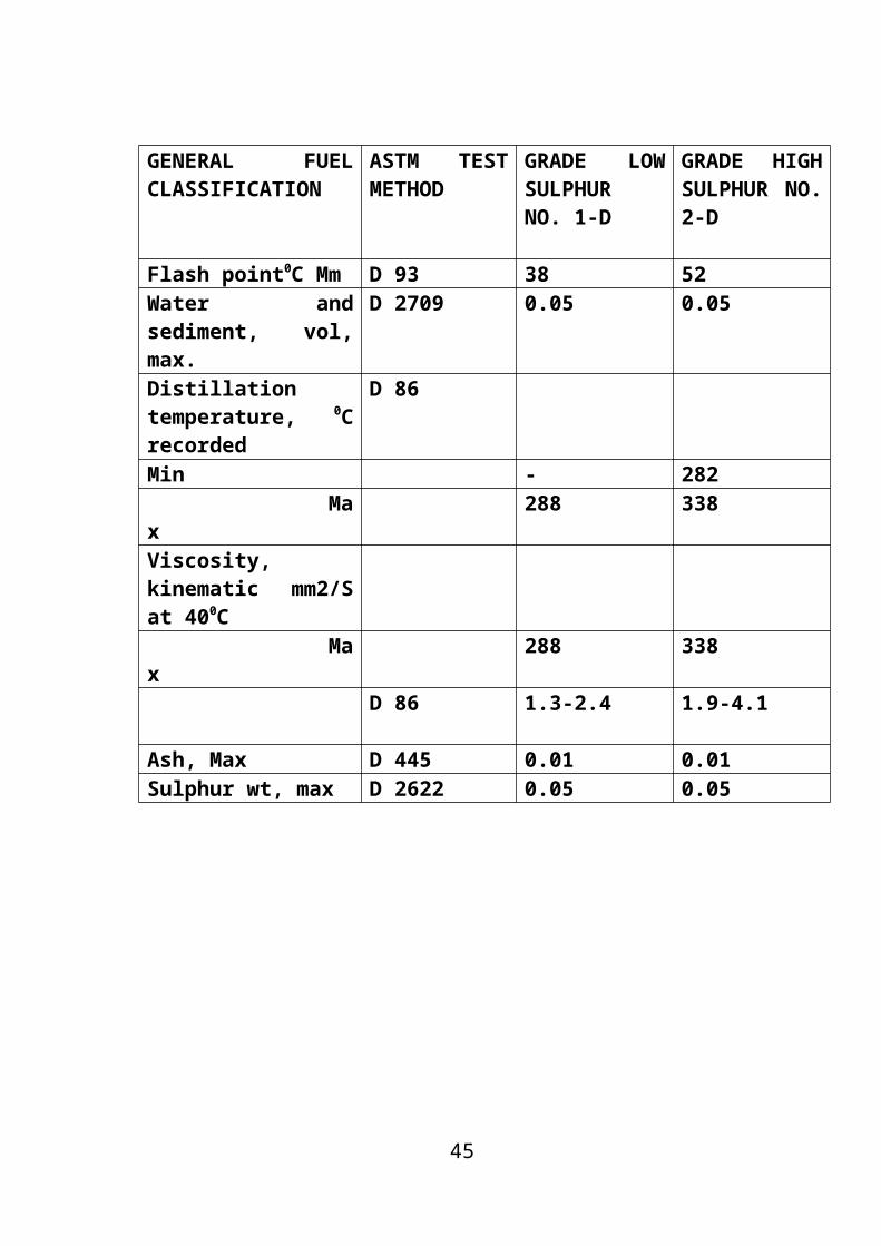
3.6.DIESEL FUEL SPECIFICATIONS
GENERAL FUEL CLASSIFICATION
ASTM TEST METHOD
GRADE LOW SULPHURNO. 1-D
GRADE HIGH SULPHUR NO. 2-D
Flash point0C Mm D 93 38 52Water and sediment, vol, max.
D 2709 0.05 0.05
Distillation temperature, 0C recorded
D 86
Min - 282 Max 288 338Viscosity, kinematic mm2/S at 400C Max 288 338
D 86 1.3-2.4 1.9-4.1
Ash, Max D 445 0.01 0.01Sulphur wt, max D 2622 0.05 0.05
29
HYDROTREATING
4.1HYDROTREATING
30
Hydrotreating (HDT) is a catalytic process , which effectively
removes sulphur and other impurities like nitrogen, oxygen and metals
from crude oil and petroleum distillates.
A refining process for treating petroleum fractions from
atmospheric or vacuum distillation units (e.g., naphthas, middle
distillates, reformer feeds, residual fuel oil, and heavy gas oil) and other
petroleum (e.g., cat cracked naphtha, coker naphtha, gas oil, etc.) in the
presence of catalysts and substantial quantities of hydrogen. Hydrotreating
includes desulfurization, removal of substances (e.g., nitrogen compounds)
that deactivate catalysts, conversion of olefins to paraffins to reduce gum
formation in gasoline, and other processes to upgrade the quality of the
fractions.
Hydrotreating applications include Hydrodesulfurisation (HDS) of
kerosene, Hydrodesulfurisation (HDS) of naphtha, Hydrodesulfurisation
(HDS )of diesel, hydrofinishing of lube oil base stocks, hydrofinishing of
wax etc.
4.2HYDROTREATING REACTIONS
The chemical reactions that are of primary interest in hydrotreating
include
1. Hydrodesulfurisation (HDS)
2. Hydrodenitrogenation (HDN)
3. Hydrodeoxygenation (HDO)
4. Hydrogenation of aromatic compounds
31

5. Saturation of olefins
6. Hydrodemetallation (HDM)
4.2.1.HYDRODESULPHURISATION
Hydrodesulfurization (HDS) is a catalytic chemical process widely
used to remove sulfur (S) from refined petroleum products such as
gasoline or petrol, jet fuel, kerosene, diesel fuel. The purpose of removing
the sulfur is to reduce the sulfur dioxide (SO2) emissions that result from
using those fuels in automotive vehicles, aircraft, railroad locomotives,
ships, gas or oil burning power plants, residential and industrial furnaces,
and other forms of fuel combustion.
R-S-R’ + 2H2 → RH + R’H +H2S
4.2.2.HYDRODENITROGENATION
The hydrogenolysis reaction is also used to reduce the nitrogen
content of a petroleum stream and removes as ammonia in a process
referred to as hydrodenitrogenation (HDN). The rate of HDN reaction
was little lower than the rate of HDS reaction.
R=N-R’+ 3H2 → RH + R’H
4.2.3.HYDRODEOXYGENATION
32

During hydrotreating, oxygen compounds in the form of naphthenic
acids, phenols, alcohols, aldehydes etc were also removed as water vapour
from the feed.
R-O-R’ + 2 H2 → RH + R’H +H2O
4.2.4.HYDRODEMETALLATION
Metals like nickel, vanadium, iron, copper, sodium etc present in
traces get adsorbed over the catalyst
R-M + ½ H2 + A → RH + M-A
4.2.5.HYDROGENATION OF AROMATIC COMPOUNDS
Aromatics combined with hydrogen and get converted in to
napthenes.
C10 H8 + 2 H2 →C10 H12
4.2.6.SATURATION OF OLEFINS
Olefins combines with hydrogen and get saturated
R=R’ + H2 → HR-R’H
4.3.UNDESIRABLE REACTIONS
33

The undesirable reactions that occur in hydrotreating are
1. Hydrocracking
2. Coking
These undesirable reactions reduce the yield of the product. At high
temperature and pressure of HDS reaction, Hydrocracking occurs as a side
reaction. Hydrocracking reaction has to be minimised, because it consumes
hydrogen, reduces the product yield and the hydrogen purity of the recycle
gas. It is limited by the selection of catalyst with low hydrocracking
capacity and working at low temperature. During HDS reaction the heavy
molecules are adsorbed on the acidic site of the catalyst and reduce the
catalytic activity
4.4.HYDROTREATING OPERATING VARIABLES
The principle operating variables affecting the performance of
hydrotreating reactions are as follows:
1. Reaction temperature
2. Hydrogen partial pressure
3. Liquid hourly space velocity and
4. Hydrogen-to-oil ratio
Reaction temperature :
34

Reactor temperature has strong influence on hydrotreating
reactions. Increasing reactor temperature increases conversion of sulphur,
nitrogen and oxygen compounds. But increasing the reactor temperature
also increases the side reactions namely, hydrocracking and coking.
Hydrogen partial pressure
Hydrogen partial pressure can be increased by increasing the
hydrogen recycle rate or hydrogen purity at a given feed rate. Increasing
hydrogen partial pressure reduces coke formation by suppressing
polymerization and condensation reactions. Adequate hydrogen-to-oil ratio
is to be maintained to have desirable cycle length.
Liquid hourly space velocity
Increasing Liquid Hourly Space Velocity(LHSV) increases feed
rate processed per unit volume of catalyst and hence reduces the severity of
hydrotreating reactions. However, lower LHSV will produce product with
low sulphur, nitrogen and oxygen. LHSV is fixed based on the design feed
rate of the unit.
Hydrogen-to-oil ratio
Hydrogen-to-oil ratio can be increased by increasing the hydrogen
recycle rate or hydrogen purity at a given feed rate and should be kept as
high as possible to decrease the rate of undesirable gases and to improve
the catalyst efficiency by avoiding coke formation.
35

CATALYST USED
5.1. HYDRO TREATING CATALYST
36

There are two types of catalyst available for hydrotreating purposes.
They are Cobalt-Molybdenum and Nickel- Molybdenum on alumina
support. Cobalt and Nickel are responsible for catalytic action whereas
Molybdenum acts as a promoter. Nickel- Molybdenum catalyst exhibits a
higher hydrogenation activity than Cobalt- Molybdenum catalyst and is
more suitable for treating cracked stocks. Very often the support material
also has catalytic action related to its chemical nature.
5.2.CATALYST OPTIONS FOR PRODUCING ULTRA LOW
SULPHUR DIESELS
Proper choice of catalyst is of paramount importance in the
production of Ultra Low Sulphur Diesel (ULSD). Recent advances in
hydrotreating catalyst technologies have significantly improved the sulphur
removal capability. The use of the most advanced hydrotreating catalyst or
catalyst system can significantly increase the desulphurisation capability of
the existing hydrotreaters.
New and improved HDS catalyst for ULSD production have been
developed and marketed by Akzo Nobel(KF 757, KF 848), Criterion
(Century and Centinel), Haldor-Topsoe(TK 573, TK 574), IFP, united
catalyst/Sud-Chemie, Advanced Refining, Exxon Mobil. Nippon Ketjen in
Japan and RIPP in China.
Improved level of desulphurisation can be obtained by using a more
active catalyst. Ther are both Co-Mo and Ni-Mo type of catalyst available
for the production of ULSD. But typically to reach ultra low sulphur levels
in the diesel product, a low space velocity and a high hydrogen partial
pressure will be needed if acceptable operating catalyst cycle is desired. Ni-
37
Mo catalyst will be a better choice for the production of ultra low sulphur
diesel at low space velocity and high hydrogen partial pressures. But for
existing units constrained by pressure and throughput, Co-Mo catalyst is a
better choice since it is better at high space velocities compared to Ni-Mo
catalyst.
In general, for low to moderate pressure and high-temperature
desulphurisation of distillate fuels, Co-Mo catalyst may be better than Ni-
Mo catalyst. For high-pressure and low-temperature conditions, Ni-Mo
catalyst performs better than Co-Mo catalyst.
The new generation catalyst exhibit 30-40% higher HDS activity
compared to previous generation catalyst (either Co-Mo or Ni-Mo). Use of
such high activity new generation catalyst will help in achieving ultra low
sulphur levels in existing units without shortening catalyst life.
About 15% more catalyst can be loaded using dense loading in
place of sock loading. This result in a 3-4oC reduction in start-of-run (SOR)
temperature for the same desulphurisation activity. Dense loading result in
a higher pressure-drop, which combined with a more uniform packing
normally obtained with dense loading will improve liquid distribution
within the catalyst bed.
38

PROCESS FLOWSHEET
39

FIGURE 5. HYDROTREATING PROCESS FLOW SHEET
40

PROCESS DESCRIPTION
41

6.PROCESS DESCRIPTION
The experiments have been carried out in a pilot plant that
was designed and assembled to perform hydrotreating operation . The
reactor of this pilot plant is a 500 cm3 vessel which can operate at
pressure of 90Kg/cm2 . the flow chart (demonstrates the schematic
process flow diagram (PFD) of this pilot plant . As it is shown in this
figure, the feed and hydrogen are mixed with a certain ratio before flowing
into the reactor. The mixed feed enters to the reactor with definite pressure
to achieve a predetermined temperature for performing the HDS reactions.
There are four thermocouples along the reactor for determining
the skin and the inside reactor temperature. The reactor product stream is
fed to a flash drum to separate gas and liquid products. The liquid product
is accumulated in a drum and the gas product is transferred for online
analysis to determine the H2S and H2 content of stream.
In addition to feed preparation, the catalyst should be presulfided
before using it with actual feed. Presulfiding of catalyst is done by
dimethyl disulfide (DMDS), which is added to the Isomax gas oil, and
circulated through the reactor bed.
This is performed to strengthen the activity and selectivity of
catalyst. To execute the procedure, an inert gas followed by a pure H2
stream is fed to the reactor. Then the reactor temperature is raised to a
certain value.
42

Presulfiding procedure was followed by a set of experiments which
was carried out to investigate the reproducibility of pilot plant setup and to
find out a suitable procedure for carrying out the main set of experiments.
The liquid samples were analyzed by Raney nickel method to
determine the total sulfur content. The results elucidated that for
improvement of reproducibility of experimental results, twelve hours
should pass to attain steady state of pilot plant system. By passing each six
hours the liquid sample is collected to analyze. The average total sulfur
content for each experiment is calculated by averaging the set of results
which are attained during the experiment. By passing one day the operating
condition can be changed to carry out another
experiment.
6.1.PROCESS OPTION FOR ULSD PRODUCTION
The main process option or types of improvements that may be
required to produce ULSD are listed and discussed below. Some of these
options can be readily implemented and may not have serious cost
implications while some other options require additional capital
investments. All these process options can improve product sulphur and
combination of them can be used to reduce sulphur significantly, but no
single option is adequate in producing ULSD.
43

Raising reactor temperature
This is obvious option to increase the desulphurisation activity. The
maximum reactor temperature is limited by design furnace outlet
temperature of the unit. Higher reactor temperature will also result in
shorter catalyst run lengths and severely restrict its usefulness.
Reducing throughputs
Reducing feed rates can decrease liquid hourly space velocities in
the reactor and thus increase the rates of hydrodesulphurisation and result
in lower product sulphur. The required throughput reduction is estimated to
be 8 times lower for the production of ULSD from a current level of 350
ppmw product sulphur making this option impractical.
Increasing hydrogen partial pressure
Increasing the hydrogen partial pressure in the reactor can reduce
the reactor SOR temperature and also reduces the rate of catalyst
deactivation. Hydrogen partial pressure can be increased by increasing the
purity of makeup hydrogen or purging the recycle gas and increasing its
purity.
Increasing the hydrogen purity by 10% of the recycle gas corresponds to
about 3oC decrease in average SOR temperature, and a 20-30% increase
cycle length. The effect of increasing hydrogen partial pressure by
increasing total pressure is less than by increasing hydrogen purity: a 10%
increase in hydrogen partial pressure corresponds to about 1oC decrease in
44
average reactor temperature. The reason for lower response is that H2S
partial pressure is also increased and total pressure is increased.
Increasing hydrogen sulphide partial pressure
Hydrogen sulphide strongly inhibits HDS reactions and its partial
pressure has great impact on hydrogen partial pressure. SOR temperature
should be raised to achieve the same HDS level when the recycle gas
contained large amount of hydrogen sulphide. This effect is lager at higher
total reactor pressure and more pronounced for Co-Mo catalysts than Ni-
Mo catalysts. Scrubbing the recycle gas to remove hydrogen sulphide will
decreased H2S partial pressure and increase hydrogen partial pressure. The
increased partial pressure of hydrogen can increase the catalyst life by
reducing coke formation.
Increasing hydrogen-to-oil ratio
Increasing hydrogen-to-oil ratio will reduce the inhibition effect of
H2S and ammonia and thereby increase the desulphurisation activity of
catalyst. This effect is rather small compared to the needs of achieving
ULSD. Increasing hydrogen-to-oil ratio by 50% may only gain 4-8% in
catalyst activity. Increasing the recycle gas-to-oil ratio also decreases the
reactor average hydrogen sulphide partial pressure and thus in turn
increases the apparent catalyst activity.
45

Adding reactor volumes
The catalyst volume can be increased either by adding new reactors
to existing units or by installing new dehydrosulphurisation units.
Generally doubling the catalyst volume results, in a 20oC decrease in
average temperature, if all other operating conditions are unchanged.
Increased catalyst volume decreases the deactivation rate of the
catalyst by reducing the start of run temperature in addition to the
availability of more deactivation temperature span. In addition, low LHSV
by itself reduces deactivation rate eve at the same SOR average reactor
temperature. Though this option requires new capital investment, it is the
best option in terms of good flexibility of feed stock and product quality.
Reactor internals
Reactor internals play a key role in improving the contact of the
reactant with the catalyst. Improper distribution of the reactants over the
catalyst will contribute to channelling through the catalyst bed, resulting in
an inefficient utilisation of the catalyst, development of hot spots and
premature catalyst deactivation due to coke formation. It was reported that
around one percent of bypassing of feed over catalyst an contribute 50 to
150 ppmw sulphur in the diesel product. Properly designed reactor internals
with good distribution of reactants over catalyst surface is necessary while
producing ultra low level of sulphur.
46
EXPERIMENTAL
DETAILS
47

7.EXPERIMENTAL DETAILS
Pilot plant studies were carried out to evaluate the performance of
DHDT catalyst.
The objective of the present work is to evaluate the DHDT catalyst
to study the effect of temperature on the performance of Diesel
hydrotreating catalyst.
The catalyst evaluation studies were carried out in a high pressure
catatest unit Procured from Vinci Technologies, France. The hydrotreating
reactions were carried out in co-current down flow mode of operation
without hydrogen recycle.
Feedstock Details
A straight run diesel sample collected from crude distillation
column was used in the pilot plant study. The characteristics of the straight
run diesel feed are presented in table 1.
Catalyst evaluated:
The DHDT catalyst is from procatalyse is NiO-MoO 3/Al2O3 type.
The characteristics of this catalyst are tabulated in table-2.
48

Table7.1.Characteristics of procatalyse hydrotreating catalyst.
Properties
Surface area , m2/gm 206
Pore volume ,ml/gm 0.55
Bulk density ,kg/L 0.737
Loss on ignition at 550o ,wt % 2.1
Single Grain Crushing Strength , DaN/mm
Average of 10 pellets
Max
Min
12.7
18.0
6.9
Bulk Crushing strength MPa 1.01
Ni O content ,wt % 4.2
Co O content ,wt % -
Mo O3 content ,wt % 18.0
49

Table 7.2.Properties of Diesel Products Hydrotreated in Pilot Plant
Reactor
Reactor pressure - 77.7 kg/cm2, Hydrogen / Oil Ratio – 150 lit/lit.
Properties Operating conditions
Reactor Temp,o C 310 320 330 340 350 360
LHSV , hr 0.7 0.7 0.7 0.7 0.7 0.7
Density @15o C
g/ml
0.8410 0.8392 0.8365 0.8345 0.8318 0.8289
API Gravity 36.8 37.1 37.7 38.1 38.7 39.3
Viscosity @ 40o
C ,cSt
4.47 4.34 4.32 4.21 4.19 4.13
Cetane Index 52.9 53.4 54.4 55.7 56.7 57.7
Sulfur , ppmw 254 137 88 67 55 42
Aniline Point, o C 76 76.5 78 79 81.5 83
ASTM D-86 Dist, Vol % ,o C
IBP 245 241 238 235 233 232
5 258 256 253 255 254 249
10 263 261 259 261 259 256
20 271 269 268 269 267 265
30 279 277 276 277 276 273
50 298 297 295 296 295 293
60 310 309 308 307 307 305
70 325 324 322 323 322 320
80 344 342 344 341 340 339
90 369 368 366 365 364 362
50
The experimental data obtained as a effect of temperature and
pressure, on the sulfur content of products hydrotreated over different
temperature is presented in the table.
The sulfur and nitrogen content of the hydrotreated products were
decreased due to the conversion of sulfur and nitrogen in the feed to
hydrogen sulfide and ammonia respectively. The aromatic content of the
products was found to decrease owing to the hydrogenation of aromatics to
naphthenes results in the decrease of density and specific gravity of
hydrotreated products. The decrease in density results in a higher API
gravity product. Saturation of olefins also increases the percentage of
saturates in the hydrotreated product. The increase in aniline point of the
hydrotreated products indicates that the product is highly paraffinic(more
saturated or less aromatic) than the feed. The decrease in aromatics reduces
the amount of carbonaceous residue in the product. The increase in aniline
point and API gravity results in a higher cetane number product , which in
turn indicates a lower ignition delay. The viscosity of the hydrotreated
products was also decreased which in turn relates to ease of starting of
diesel engine.
7.1.EFFECT OF TEMPERATURE
The effect of reactor temperature on product quality was studied
between 310o C and 360oc at 0.7 liquid hourly space velocity and
77.7 Kg/cm2.
The tables show the effect of reactor temperature on product
sulfur hydrotreated over catalyst NiO-MoO 3/Al2O3 at a hydrogen-to-oil
ratio of 150L/L.
51

With catalyst and 77.7kg/cm2 reactor pressure, the product with a
sulfur content of 254ppmw to 42 ppmw was obtained at a reactor
temperature of 360oC and a LHSV of 0.7h-1 indicating a conversion of
about 98.7 %. As expected ,highest conversion of sulfur compounds was
achieved at the severe most operating conditions employed.
From the table , it is shown that increase in temperature has
decreased the level of sulphur content in the feed. At a temperature of
310oC the sulfur content was 254 ppmw. As the temperature increases to
360oC sulphur content decreases to 42 ppmw.
It was found that the sulfur content of the product decreases with
increasing reactor temperature at constant LHSV. The effect of reactor
temperature on product sulfur was more pronounced at higher liquid hourly
space velocities and the sulfur conversion decrease at higher reactor
temperature.
7.2.EFFECT OF PRESSURE
The data show that the increase in the reactor pressure improved
product quality. The API gravity and cetane number of the hydrotreated
products increased and the sulfur and aromatic contents decreased with
increased reactor pressure. The rate of hydrodesulfurisation reaction is
faster at higher pressure. The reason for this effect of pressure is considered
to be that the higher the pressure better is the contact between hydrogen,
and hydrocarbons and the catalyst. In general, the effect is considerably
weaker at higher pressures i.e., sulfur conversion decreases with increasing
pressure. However, very high pressures reduce the activity of the catalyst,
owing to the adhesion of carbon to its surface.
52

At higher operating pressures, the effect of pressure on sulfur
conversion becomes insignificant. The partial pressure and the
concentration of hydrogen sulfide in the gas phase goes up as the
conversion of sulfur compounds increases. Beyond a certain operating
pressure, the concentration of hydrogen sulfide in the gas phase decreases
because of the increase in solubility of hydrogen sulfide in liquid phase.
In general, the hydrotreated products showed a decrease in density,
viscosity, sulfur, nitrogen and aromatic contents, and increase in API
gravity, aniline point, cetane number and saturates content when the
temperature is increased.
The polyaromatics content of the hydrotreated products was well
below 11wt% meeting Euro-III as well as Euro-IV specifications.
7.3.EFFECT OF ANILINE POINT
This is an approximate measure of the aromatic content of a
hydrocarbon fuel. It is defined as the lowest temperature at which a fuel oil
is completely miscible with an equal volume of aniline. Aniline is an
aromatic compound and aromatics are more miscible in aniline than are
paraffins. Hence, the lower the aniline point, the higher the aromatics
content in the fuel oil. The higher the aromatics content, the lower the
cetane number of the fuel. The aniline point can thus be used to indicate the
probable ignition behavior of a diesel fuel. aniline point increases from 76
to 83.
53

7.4.EFFECT OF IBP
According to American Society for Testing and Materials
petroleum- analysis distillation procedures, the recorded temperature when
the first drop of distilled vapor is liquefied and falls from the end of the
condenser.
The initial boiling point in the feed is actually higher than that of
the product. So when the initial boiling point is taken for 5 vol % it has a
certain higher temperature and finally if the temperature is noted for 90
vol % certainly it will have a temperature less than the 5 vol %.
7.5.OVERALL HDS KINETICS
The kinetics for sulfur removal from real feedstocks are complex
and depend on the distribution of sulfur compounds and the degree of
conversion. For industrial feedstocks, the structural differences between the
sulfur containing molecules make it impractical to produce a complex rate
equation to describe the HDS kinetics. Hence, in the present work the
following conventional power law kinetic expression was used (Juarez et
al.1999):
where S is the sulfur content in the feedstock (wt%), S the sulfur content in
the product (w%). n the apparent reaction order and k is the kinetic
constant.
54

The data at various space velocities, temperatures and product
sulfur contents were used for kinetic data analysis and to determine the
following apparent reaction orders and activation energies.
Diesel indx
The Diesel Index indicates the ignition quality of the fuel. It is
found to correlate, approximately, to the cetane number of commercial
fuels. It is obtained by the following equation
Diesel Index =
aniline po int (o F ) x Degrees API gravity (60 o F )100
Diesel Index and cetane number are usually about 50. Lower values will
result in smoky exhaust
Cetane improvement
Cetane number or CN is a measurement of the combustion quality
of diesel fuel during compression ignition. It is a significant expression of
the quality of a diesel fuel. Cetane has improved significantly . as the
temperature is increased the cetane number is increased 52.9 to 57.7.
Cetane improvers
55

These are compounds that readily decompose to give free radicals
and thus enhance the rate of chain initiation in diesel combustion. They
promote fast oxidation of fuels and thus improve their ignition
characteristics. Chemical compounds such as alkyl nitrates, ether nitrates,
dinitrates of polyethylene glycols and certain peroxides are well known
cetane improvers. In general, however, in view of their low cost and ease
of handling, most commercial significance has been attached to different
primary alkyl nitrates.
Cetane index
Cetane index is used as a substitute for the cetane number of diesel
fuel. The cetane index is calculated based on the fuel's density and
distillation range (ASTM D86). There are two methods used, ASTM D976
and D4737.
56
DESIGN OF FEED
VESSEL & SEPERATOR
OF A PILOT PLANT
57

8.1. DESIGN OF FEED VESSEL :
Design of feed vessel of hydro treater in a pilot plant
The feed vessel is a unfired pressure vessel . Pressure vessels used
in industry are leak-tight pressure containers, usually cylindrical or
spherical in shape, with different head configurations. They are usually
made from carbon or stainless steel and assembled by welding. Early
operation of pressure vessels and boilers resulted in numerous explosions,
causing loss of life and considerable property damage. In 1925 the
committee issued a set of rules for the design and construction of unfired
pressure vessels.
8.2.DESIGN CRITERIA
The Code design criteria consist of basic rules specifying the design
method, design load, allowable stress, acceptable material, and fabrication,
inspection certification requirements for vessel construction.The design
method known as "design by rule" uses design pressure, allowable stress,
and a design formula compatible with the geometry of the part to calculate
the minimum required thickness of the part. This procedure minimizes the
amount of analysis required to ensure that the vessel will not rupture or
undergo excessive distortion. In conjunction with specifying the vessel
thickness, the Code contains many construction details that must be
followed. Where vessels are subjected to complex loadings such as
58

cyclic, thermal, or localized loads, and where significant discontinuities
exist, the Code requires a more rigorous analysis to be performed. This
method is known as the "design by analysis" method.
8.3.SPECIFICATIONS
1. Here the operation is considered to be running for 12 hours .
2. Maximum liquid flow rate : 600 ml/hr.
(pumping capacity)
3. For a day, the flow rate is : 7.2 lt /day
4. Consider 30% excess for the N2 inert atmosphere.
5. So Z, we have to design the capacity of the vessel
approximately to be 10 litres.
6. Let the feed vessel considered to be cylindrical.
7. Volume = (Π/4) d2 L
8. Length of the cylindrical vessel = 320 mm
9. Diameter of the cylindrical vessel = 200m.
10. so, the volume = 10 litres
11. L/D ratio = 320/200 =1.6
MATERIAL OF CONSTRUCTION:
59

1. The material used here is SS316 .
2. It is stainless steel and the maximum allowable stress is
18100.
3. It can withstand temp of about 500 o C & pressure of about
150 Kg/cm2 .
TABLE8.4.Thickness calculation
DIMENSIONS UNIT VALUES
Design pressure Kg/cm2 3
Design temperature oC 150
Inside radius Mm 100
Maximum allowable stress PSI 18100
Joint efficiency (from table uw12) % 0.7
Circulated thickness (circular stress) Mm 3.42
Circulated thickness (longitudinal stress) Mm 1.71
Internal corrosion allowance Mm 0
External corrosion allowance Mm 1.25
Total thickness Mm 4.67
Desired thickness Mm 12
60

TABLE 8.5. Max Allowable stress in PSI
UPTO
100OF
UPTO
37.7OC
SS 316 SS 316L SS 304 MS
200 93.33 18800 14100 15700 11500
300 148.89 18400 12700 14100 11500
400 204.44 18100 11700 12900 11500
500 260.00 18000 10900 12100 11500
600 315.56 17000 10400 11400 11500
650 343.33 16700 10200 11200 11500
700 371.11 16300 10000 11100 11500
750 398.89 16100 9800 10800
800 426.67 15900 9600 10600
850 454.44 15700 9400 10400
900 482.22 15600 10200
950 510.00 15400 10000
8.6.CALCULATION OF CIRCULAR THICKNESS:
(i) (Circular stress)
61

((D.P *14.5) * (I.R/25.4) / ((M.A.S*J.E) - 0.6*D.P*14.5)) *25.4
((1 * 14.5) * (100/25.4) / ((18100*0.7) - 0.6*1*14.5))* 25.4 = 3.42
(ii) (Longitudinal stress):
((D.P*14.5)*(I.R/25.4) /((2*M.A.S*J.E) + (0.4*D.P*14.5))* 25.4
((1*14.5) * (100/25.4) / ((2*18100*0.7) +(0.4*1*14.5))*25.4 = 1.71
Total thickness :
(C.T.C+I.C.A+E.C.A)
(3.42+ 0 + 1.25 ) = 4.67
External pressure : 0
62

8.7.DESIGN OF GAS LIQUID SEPERATOR
Figure8.7. GAS LIQUID SEPERATOR
A vapor–liquid separator is a device used in several
industrial applications to separate a vapor–liquid mixture. For the common
variety, gravity is utilized in a vertical vessel to cause the liquid to settle to
the bottom of the vessel, where it is withdrawn. In low
gravity environments such as a space station, a common liquid separator
will not function because gravity is not usable as a separation mechanism.
In this case, centrifugal force needs to be utilized in a spinning centrifugal
separator to drive liquid towards the outer edge of the chamber for removal.
63

Gaseous components migrate towards the center. The gas outlet may itself
be surrounding by a spinning mesh screen or grating, so that any liquid that
does approach the outlet strikes the grating, is accelerated, and thrown
away from the outlet.
SPECIFICATIONS
1. Operation : Continous
2. Consider the seperator is occupied with 60% liquid & 40%
gas.
3. Volume : 1 lt
4. L/D ratio : 165/90 = 1.8
5. Length : 165 mm
6. Diameter : 90 mm
7. M.O.C : SS316.
8.8.Thickness calculation
DIMENSIONS UNIT VALUES
Design pressure Kg/cm2 77.7
Design temperature oC 400
Inside radius Mm 45
Maximum allowable stress PSI 18100
Joint efficiency (from table uw12) % 0.7
Circulated thickness (circular stress) Mm 1.6
Circulated thickness (longitudinal stress) Mm 1.6
Internal corrosion allowance Mm 0
64

External corrosion allowance Mm 1.25
Total thickness Mm 2.85
Desired thickness Mm 12
8.9.Calculation of circular thickness:
(i) (Circular stress)
((D.P *14.5) * (I.R/25.4) / ((M.A.S*J.E) 0.6*D.P*14.5))*25.4
(
(77.7 * 14.5) * (45/25.4) / ((18100*0.7) - 0.6*77.7*14.5))*25.4 = 1.6
(ii) (Longitudinal stress):
((D.P*14.5)*(I.R/25.4)/((2*M.A.S*J.E) + (0.4*D.P*14.5))*25.4
((77.7*14.5) * (45/25.4) / ((2*18100*0.7) +(0.4*77.7*14.5))*25.4 = 1.6
Total thickness :
(C.T.C+I.C.A+E.C.A)
(1.6+ 0 + 1.25 ) = 2.85
65

External pressure : 0
FIGURE 8.10 CETANE RESPONSE FOR VARIOUS CETANE
IMPROVERS
66

Scope of the project work
The scope of the project work includes the following:
1. To evaluate the performance of various activity new
generation hydrotreating catalyst in a pilot plant trickle-bed reactor
67

to determine the required severity level and different combination of
catalyst for the production of ultra low sulphur diesel.
2. To study the effect of reactor temperature and liquid hourly
space velocity on product quality at constant reactor pressure and
hydrogen-to-oil ratio using different hydrotreating catalysts.
Applications
1. Useful in the production of Ultra Low Sulfur Diesel
(ULSD) as per fuel quality regulations assigned by government.
2. We are able to minimize pollution in the environment by
reducing mainly sulfur & also other impurities present in the diesel
by hydro treating process.
68

RESULTS &
DISCUSSIONS
9.RESULTS & DISCUSSIONS
The hydrotreated products from pilot plant were characterized in
detail to study the extent Hydrodesulphurisation and cetane improvement.
69
1. Increase in temperature has increased the HDS activity as
evidenced by reduction in sulphur content progressively of 254
ppmw to 42ppmw.
2. Increase in temperature has beneficially increased the
important property namely Cetane Index also. The Cetane Index
increase observed was 4.5 to 10.5 units
CONCLUSIONS
The pilot plant studies help in concluding the demand less than
50ppm product sulphur can be achieved from high sulphur Raw Diesel
Sample. The Cetane improvement is remarkable from Diesel feed which
has high aromatic content.
APPENDIX
1) Determination of Density (ASTM D-4052)
The density, specific gravity and API volume (approximately
0.7ml) of diesel was introduced into an oscillating sample tube. The change
70

in oscillating frequency caused by the change in mass of the tube was
measured. Using the calibration data the density, specific gravity and API
gravity were determined.
2) Determination of Kinematic Viscosity (ASTM D-445)
Kinematic viscosity is the resistance to flow of fluid under gravity.
Kinematic Viscosity was determined at 40o C using Ubbelohde’s
Viscometer. Time was measured for a fixed volume of liquid to flow under
gravity through the capillary of a calibrated viscometer under a
reproducible driving head and at a closely controlled and known
temperature. The kinematic viscosity is the product of the measured flow
time and the calibration constant of the viscometer.
3) Determination of Pour Point (ASTM D-97)
The Pour Point is the lowest temperature, expressed as a multiple of
3o C at which the oil is observed to flow when cooled and examined under
prescribed conditions.
The Pour Point was determined using Pour Point apparatus. The
Pour Point is an index of the lowest temperature of its utility for certain
applications.
After preliminary heating, the sample was cooled at a specified rate
and examined at intervals of 3o C for its flow characteristics. The lowest
temperature at which movement of the sample occurred was observed and
recorded as the pour point.
71

4) Determination of Aniline Point (ASTM D-611)
Aniline Point is the minimum equilibrium solution temperature, in
degree Celsius, of a mixture of equal volumes of aniline and the sample
under test. The aniline point is used to estimate the aromatic content of
mixture.
Specified equal volumes of aniline and sample were placed in a
tube and mixed mechanically. The mixture was heated at a controlled rate
and the temperature at which two phases become miscible was noted. The
mixture was then cooled at a controlled rate and the temperature at which
two phases separate was recorded as the aniline point.
5) Determination of Flash Point (ASTM D-93)
Flash Pont is the minimum temperature at which the vapors from
test sample will give a momentary flash on application of a standard flame
under specific test conditions. The flash point is determined using Pensky-
Martens closed cup apparatus.
A brass test cup of specified dimensions, filled to the mark with test
sample and fitted with a cover of specified dimensions, was heated and the
sample stirred at specified rates. An ignition source was directed into the
test cup at regular intervals with simultaneous interruption of the stirring,
until a flash detected. The temperature at which flash was detected is
reported as flash point.
6) Determination of Ramsbottom Carbon Residue (ASTM D-524)
72

It is the amount of carbonaceous residue formed by evaporation and
thermal degradation (phyrolysis) of the sample.
The sample was weighed into a special glass bulb having a capillary
opening and placed in a metal furnace maintained at approximately 550o C.
The sample was quickly heated to the point at which all volatile matter is
evaporated out of the bulb with or without decomposition while the heavier
residue remaining in the bulb undergoes cracking and reactions. In the
latter portion of the heating period, the cole or carbon residue was
subjected to further decomposition or slight oxidation due to the possibility
of breathing air in to the bulb. After a specified heating period, the bulb
was removed from the bath, cooled in a dessicator, and the residue
remaining was again weighed and expressed as a percentage of the original
sample and reported as Ramsbottom Carbon Residue.
Provision is made for determining the proper operating
characteristics of the furnace with a controlled bulb containing a
thermocouple, which must give a specified time-temperature relationship.
7) Determination of Total Sulfur (ASTM D-2622)
The total sulfur content of diesel is determined by Energy
Dispersive S-ray Fluorescence spectrometry.
The diesel sample is placed in a beam emitted from the X-ray
source. The resultant excited characteristics X-radiation is measured and
the accumulated count is compared with counts from previously prepared
calibration samples to obtain the sulfur concentration in mass%.
8) Determination of Total Aromatics and Total Saturates (IP-391)
73

Diesel sample contains monoaromatic, diaromatic and polyaromatic
hydrocarbons.
A known mass of diesel sample was diluted in the mobile phase (n-
heptane) and a fixed volume of the solution was injected into a High
Performance Liquid Chromatography (HPLC) fitted with a polar column.
This column has little affinity for the non-aromatic hydrocarbons whilst
exhibiting a pronounced selectivity for aromatic hydrocarbons. As a result
of this selectivity the aromatic hydrocarbons are separated from the non-
aromatic hydrocarbons into distinct bands according to their ring structure
i.e., MAH, DAH, PAH compounds. At a pre-determined time, after the
elution of DAHs the column was back flused to elute the PHAs as a single
Sharp band.
The column was connected to a refractive index detector that
detects the components as they elute from the column. The electronic
signal from the detector was continually monitored by a data processor.
The amplitudes of the signal from the sample aromatics were compared
with those obtained from previously run calibration standards in order to
calculate % mass of MAHs, DAHs, PAHs in the diesel. The sum of MAHs,
DAHs and PAHs is reported as the total content of the aromatic contents in
the sample.
The Saturates content of the sample is obtained by subtracting the total
aromatics content from 100 percent.
9) Determination of Nitrogen (ASTM D-4629)
ANTEK analyzer as per ASTM D-4629 method determines the
Nitrogen content of the sample.
74

10) Determination of ASTM Distillation Characteristics (ASTM D-
86)
The distillation characteristics of the sample were determined using
ASTM D-86 Distillation apparatus.
A 100 mL specimen of the sample was distilled under prescribed
conditions. The distillation was performed in a laboratory batch distillation
unit at ambient pressure under conditions that were designed to provide
approximately one theoretical plate fraction. Systematic observations of
temperature readings and volumes of condensate were made. The volume
of the residue and the losses were also recorded.
At the conclusion of the distillation the observed vapor
temperatures can be corrected for barometric pressure and the data were
examined for conformance to procedural requirements, such as distillation
rates. The test was repeated if any specified conditions have not been met.
Test results are commonly expressed as percentage recovered and
corresponding temperature in a table.
75

REFERENCES
References
1. Babich I.V. and Moulijn J.A. (2002), ‘ science and technology of
novel processes for deep sulfurisation of oil refinery streams : a review’,
fuel, vol.82,pp.607-631.
76

2. Bhaskar M., Valavarasu G., and Balaraman K.S (2000), ‘deep
desulfurization of a diesel blend in a pilot plant trickle bed reactor ’,
Petroleum Science and Technology, vol.18, No.7 & 8, pp.851-869.
3. Bhaskar M., Valavarasu G., Selvavathi V. and Sairam B.(2004),
‘Production of ultra Low Sulfur Diesel-Catalyst and process options’, XII
Refinery Technology Meet, Goa, India, September23-25,2004;pp.474-486.
4. Bhaskar M., Valavarasu G., Sairam B., Balaraman K.S and Balu
K.(2004),
‘Three Phase Reactor Model to Simulate the performance of pilot-plant
Trickle –Bed Reactors Sustaining Hydrotreating Reactions’, Ind.
Eng.Chem
Res., Vol.43,pp.6654-6669.
5. Chunshan Song (2003), ‘An overview of new approaches to deep
desulfurization for ultra-clean gasoline, diesel fuel and jet fuel’, Catalysis
today , Vol.86,pp.211-263.
6. Lamourelle A.P and Nelson D.E.(2001), ‘ Ultra low aromatic
diesel’, Petroleum Technology Quarterly , june 2001.
7. Perry’s chemical engineers’ handbook. — 7th ed. /
prepared by a staff of specialists under the editorial
direction of late editor Robert H.
Perry : editor, Don W. Green : associate editor, James
O’Hara Maloney.
77

8. Salvatore T.JR. and Gunter P.M (2004), ‘ Fundamentals of ULSD
Production’, Petroleum Technology Quarterly – Summer 2004,pp.29-35.
78


![Modelado del proceso de hidrotratamiento de diésel … · Modelado del proceso de hidrotratamiento de diésel Diesel hydrotreating process modelling ... Mapiour et al. [9] estudiaron](https://img.dokumen.tips/doc/110x75/5baeef8709d3f290738debfd/modelado-del-proceso-de-hidrotratamiento-de-diesel-modelado-del-proceso-de.jpg)