Embed Size (px)
DESCRIPTION
This is for Engineering students who want to research in wireless technology.
Citation preview
A
RESEARCH PROPOSAL
On
MIMO
Wireless System Technology
Submitted to
Cultural & Public Relations Department
Embassy of Japan
Submitted by
Deep Raj Bhujel
Bachelor’s Degree in Engineering
Electronics and Communication Engineering
30-May-2013
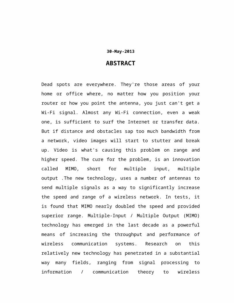
ABSTRACT
Dead spots are everywhere. They're those areas of your home or office where, no
matter how you position your router or how you point the antenna, you just can't get a
Wi-Fi signal. Almost any Wi-Fi connection, even a weak one, is sufficient to surf the
Internet or transfer data. But if distance and obstacles sap too much bandwidth from a
network, video images will start to stutter and break up. Video is what's causing this
problem on range and higher speed. The cure for the problem, is an innovation called
MIMO, short for multiple input, multiple output .The new technology, uses a number
of antennas to send multiple signals as a way to significantly increase the speed and
range of a wireless network. In tests, it is found that MIMO nearly doubled the speed
and provided superior range. Multiple-Input / Multiple Output (MIMO) technology
has emerged in the last decade as a powerful means of increasing the throughput and
performance of wireless communication systems. Research on this relatively new
technology has penetrated in a substantial way many fields, ranging from signal
processing to information / communication theory to wireless propagation. Equally
importantly, MIMO technology has made its way into current and next generation
communication standards and systems. In this paper, I will provide an overview of
MIMO systems, starting with the fundamentals of capacity, random channels, basic
transceiver architectures, diversity, space-time coding and channel estimation. I will
then review some more recent results in the areas of diversity versus multiplexing
trade-offs, input optimization / precoding, fundamental limits of coherent operation
and multi-user MIMO, including systems with interference. Finally we will cover
certain applications of MIMO techniques in current wireless systems.
TABLE OF CONTENTS
ABSTRACT ………………………………………………………………………....i
TABLE OF CONTENTS …………………………………………………………...ii
LIST OF FIGURES ………………………………………………………………..iii
LIST OF TABLES …………………………………………………………………iii
LIST OF SYMBOLS AND ABBREVIATIONS …………………………………iv
1. MOTIVATION AND OBJECTIVES …………………………………………....1
1.1 Motivation …………………………………………………………….....1
1.2 Objectives ………………………………………………………………..1
2. LITERATURE REVIEW ………………………………………………………...3
2.1 Introduction ……………………………………………………………...3
2.2 Concept of MIMO …………………………………………………….....5
2.3 Principle ……………………………………………………………….....7
2.4 How It Works ……………………………………………………………8
2.5 Channel Capacity ………………………………………………………...9
2.6 Antenna Selection ………………………………………………………..9
2.7 Outage Capacity ………………………………………………………...10
3. MIMO APPLICATIONS IN 3G WIRELESS SYSTEMS AND BEYOND ……11
3.1 Background ……………………………………………………………...11
3.2 MIMO in 3G Wireless Systems and Beyond …………………………....11
4. ACTIVITIES ……………………………………………………………………...13
4.1 MIMO testing …………………………………………………………....13
5. OUTCOMES ……………………………………………………………………..15
5.1 Applications of MIMO ………………………………………………….15
6. CONCLUSIONS AND FUTURE TRENDS …………………………………….16
7. REFERENCES …………………………………………………………………...17

LIST OF FIGURES
Figure 1 : A Multi-channel Network …………………………………………………3
Figure 2 : Understanding of SISO, SIMO, MISO and MIMO ……………………...6
Figure 3 : Working of MIMO ………………………………………………………..8
Figure 4 : MIMO channel model ……………………………………………………13
LIST OF TABLES
Table 1 : Peak Data Rates of Various MIMO Architectures ………………………..11
LIST OF SYMBOLS AND ABBREVIATIONS
MIMO …………………….Multiple Input Multiple Output
SISO ……………………...Single Input Single Output
SIMO …………………….Single Input Multiple Output
MISO …………………….Multiple Input Single Output
QoS ………………………Quality of Service
WLAN ………………..….Wireless Local Area Network
IEE ……………………….Institute of Electrical and Electronics Engineers
WiMAX ………………….Worldwide Interoperability for Microwave Access
HSDPA…………………...High-Speed Digital Packet Access
HSDPA+………………….High-Speed Digital Packet Access plus
MEAs……………………..Multiple-Element Antenna systems
ARQ ……………………...Automatic Repeat Request
3GPP ……………………..3rd Generation Partnership Project
OFDM…………………….Orthogonal Frequency Division Multiplexing
OFDMA…………………..Orthogonal Frequency Division Multiple Access
RRC……………………….Radio Resource Control
CSI………………………..Channel State Information
ITU………………………..International Telecommunication Union
BLAST ……………………Basic Local Alignment Search Tool
LTE ……………………….Long Term Evolution
PAR………………………Peak-to-Average Ratio
VSG………………………Vector Signal Generator
VSA………………………Vector Signal Analyzer
TX ………………………..Transmitter
RX ………………………..Receiver
IST-MASCOT …………...Information Society Technologies Multiple Access Space-
Time Coding Testbed
1. MOTIVATION AND OBJECTIVES
1.1 Motivation
Comprehensive broadband, integrated mobile communication will step into all mobile
4G service and communication. The 4G will be the migration from the other
generation of mobile services to overcome the limitation of boundary and achieve the
integration. The 4G of mobile services aims to total wireless.
The 4G will be developed to provide high speed transmission, next generation
internet support, seamless integrated services and coverage, utilization of higher
frequency, lower system cost, seamless personal mobility, mobile multimedia,
sufficient spectrum use, quality of service (QoS), reconfigurable network and end-to-
end IP systems.
In conventional wireless communication, a single antenna is used at the source and
another antenna is used at destination. In many cases, it gives rise to problem with
multipath fading, making difficult to meet promises aim by the 4G.
The solution to multipath fading can be solved using MIMO technology. The
following paper will outline the concept of MIMO technology and why it’s superior
to present the present day technology. That is the reason I want my research on
MIMO technology exploration and advancement to make the wireless service hassle-
free and easier.
1.2 Objectives
MIMO technology promises higher data rate, higher quality of service and better
reliability by exploiting antenna array at both the transmitter and the receiver. Signals
at both sides (transmitter and receiver) are mixed such that they either generate
multiple parallel, spatial bit pipes and/or add diversity to decrease the bit-error rate.
Diversity helps in selecting the clearest signal out of many signals, resulting in lower
bit-error rate. Multiple bit pipes effectively increase the data rate (quantitative
improvement), whereas the reduced bit-error rate improve the quality of service,
throughput and reliability (qualitative improvement).
The fundamental gain in MIMO is increased data rate. Why not use more bandwidth
or complex modulation scheme to increase the data rate? The use of more bandwidth
depends upon the availability of spectrum and again the use may be difficult to meet
the spectral efficiency. All wireless devices use a particular part of radio spectrum.
Air traffic radar, for example, operates between 960 and 1215 megahertz and
cellphone between 824 to 849 megahertz. As growing number of wireless devices
enter the consumer market, the spectrum becomes congested every year. MIMO has
potential to expand radio capacity and relieve the burden on existing bandwidth.
By spreading the transmitted signal over the multiple paths, the MIMO technology
increases the chances of signal reception at receiver. It also increases the range of
operation.
Multipath fading causes the distortion by scrambling the copy of the signals reaching
the receiver via multiple paths on bouncing of the objects. Then how does the
multipath signals work in MIMO? Proper algorithms are used at both the transmitter
and receiver to analyses the signal received from different path and different antenna
of array.
Proper spacing of antenna and signal analysis via a matrix manipulation technology
that cross-correlate the signals are the requirement of MIMO technology.
2. LITERATURE REVIEW
2.1 Introduction
Multiple Input Multiple Output (MIMO) is a smart antenna technique that increases
speed, range, reliability and spectral efficiency for wireless systems. Given the
demands that applications are placing on WLANs, MIMO chipsets will figure
prominently in new access points and network interface cards.
MIMO is one technology being considered a standard for next-generation that boosts
throughput to 100 Mbit/sec. In the meantime, proprietary MIMO technology
improves performance of existing networks.
A conventional radio (or telephony) uses one antenna to transmit a DataStream as
shown in figure 1. A typical smart antenna radio, on the other hand, uses multiple
antennas. This design helps combat distortion and interference. Examples of multiple-
antenna techniques include switched antenna diversity selection, radio-frequency
beam forming, digital beam forming and adaptive diversity combining.
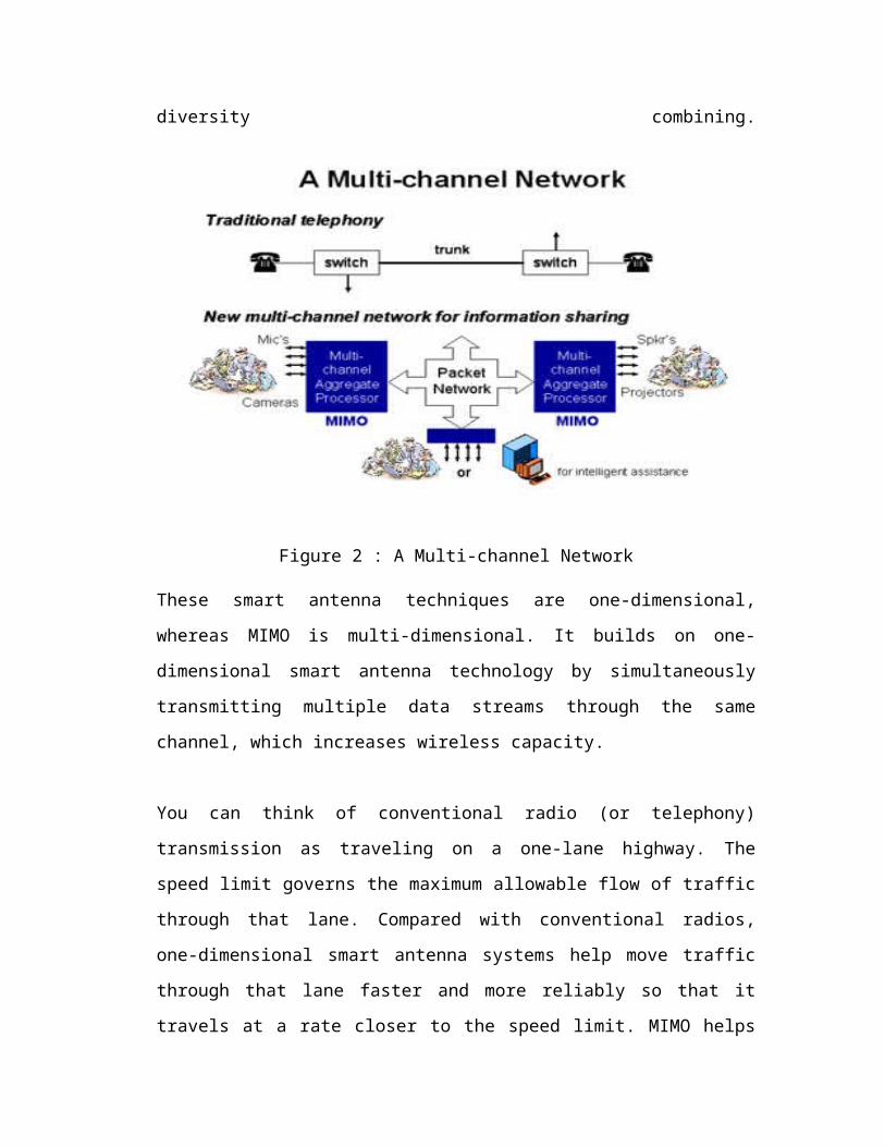
Figure 2 : A Multi-channel Network
These smart antenna techniques are one-dimensional, whereas MIMO is multi-
dimensional. It builds on one-dimensional smart antenna technology by
simultaneously transmitting multiple data streams through the same channel, which
increases wireless capacity.
You can think of conventional radio (or telephony) transmission as traveling on a
one-lane highway. The speed limit governs the maximum allowable flow of traffic
through that lane. Compared with conventional radios, one-dimensional smart
antenna systems help move traffic through that lane faster and more reliably so that it
travels at a rate closer to the speed limit. MIMO helps traffic move at the speed limit
and opens more lanes. The number of lanes that are opened as shown in figure 1
multiplies the rate of traffic flow.
A characteristic of radio transmission called multipath, which had previously been
considered an impairment to radio transmission, is actually a gift of nature. Multipath
occurs when signals sent from a transmitter reflect off objects in the environment and
take multiple paths to the receiver. The researchers showed that multipath could be
exploited to multiplicatively increase the capacity of a radio system.
If each multipath route could be treated as a separate channel, it would be as if each
route were a separate virtual wire. A channel with multipath then would be like a
bundle of virtual wires.
To exploit the benefits the virtual wires offer, MIMO uses multiple, spatially
separated antennas. MIMO encodes a high-speed DataStream across multiple
antennas. Each antenna carries a separate, lower-speed stream. Multipath virtual
wires are utilized to send the lower-speed streams simultaneously.
But wireless is not as well behaved as a bundle of wires. Each signal transmitted in a
multipath environment travels multiple routes. This makes a wireless system act like
a bundle of wires with a great deal of leakage between them, causing transmitted
signals to jumble together. The MIMO receiver uses mathematical algorithms to
unravel and recover the transmitted signals.
2.2 Concept of MIMO
In radio, MIMO (commonly pronounced my-moh or me-moh), is the use of multiple
antennas at both the transmitter and receiver to improve communication performance.
It is one of several forms of smart antenna technology. Note that the terms input and
output refer to the radio channel carrying the signal, not to the devices having
antennas.
MIMO technology has attracted attention in wireless communications, because it
offers significant increases in data throughput and link range without additional
bandwidth or increased transmit power. It achieves this goal by spreading the same
total transmit power over the antennas to achieve an array gain that improves the
spectral efficiency (more bits per second per hertz of bandwidth) and/or to achieve a
diversity gain that improves the link reliability (reduced fading). Because of these
properties, MIMO is an important part of modern wireless communication standards
such as IEEE 802.11n (Wi-Fi), 4G, 3GPP Long Term Evolution, WiMAX and
HSPA+.
Wireless channels input and output modulated signals. For the purpose of modulation,
the two basic things are considered are frequency and time. The frequency plan and
time plan use ‘bits per hertz’ and ‘bits per second’ as measures for data rate
transportation.
A new dimension to upgrade the data transportation rate is spatial dimension. This is
the concept behind MIMO technology.
MIMO technology may be seen as an upgrade of SIMO and MISO. All three
technologies namely SIMO, MISO and MIMO use multipaths for increasing data
rate, throughput and reliability. Multiple paths are used by multiple transmit antenna
and multiple receiver antenna.
Multiple antennas at one end either at transmitter or at the receiver were in use long
ago. The then use of multiple antennas aimed at beam forming and spatial diversity,
which are mainly used to increase the signal to noise ratio. The improved signal to
noise ratio decreases the bit-error rate.
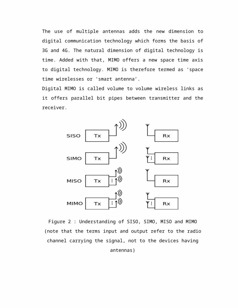
The use of multiple antennas adds the new dimension to digital communication
technology which forms the basis of 3G and 4G. The natural dimension of digital
technology is time. Added with that, MIMO offers a new space time axis to digital
technology. MIMO is therefore termed as ‘space time wirelesses or ‘smart antenna’.
Digital MIMO is called volume to volume wireless links as it offers parallel bit pipes
between transmitter and the receiver.
Figure 2 : Understanding of SISO, SIMO, MISO and MIMO (note that the terms
input and output refer to the radio channel carrying the signal, not to the devices
having antennas)
2.3 Principle
The increase in spectral efficiency offered by MIMO systems is based on the
utilization of space (or antenna) diversity at both the transmitter and the receiver. Due
to the utilization of space diversity, MIMO systems are also referred to as MEAs.
With a MIMO system, the data stream from a single user is de-multiplexed into nT
separate sub-streams. The number nT equals the number of transmit antennas. Each
sub-stream is then encoded into channel symbols. It is common to impose the same
data rate on all transmitters, but adaptive modulation rate can also be utilized on each
of the sub-streams. The signals are received by nR receive antennas. With this
transmission scheme, there is a linear increase in spectral efficiency compared to a
logarithmic increase in more traditional systems utilizing receive diversity or no
diversity. The high spectral efficiencies attained by a MIMO system are enabled by
the fact that in a rich scattering environment, the signals from each individual
transmitter appear highly uncorrelated at each of the receive antennas. When the
signals are conveyed through uncorrelated channels between the transmitter and
receiver, the signals corresponding to each of the individual transmit antennas have
attained different spatial signatures. The receiver can use these differences in spatial
signature to simultaneously and at the same frequency separate the signals that
originated from different transmit antennas.
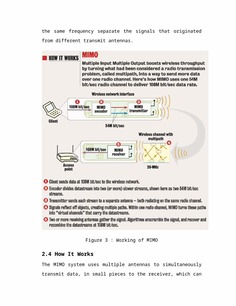
Figure 3 : Working of MIMO
2.4 How It Works
The MIMO system uses multiple antennas to simultaneously transmit data, in small
pieces to the receiver, which can process the data flows and put them back together.
This process, called spatial multiplexing, proportionally boosts the data-transmission
speed by a factor equal to the number of transmitting antennas. In addition, since all
data is transmitted both in the same frequency band and with separate spatial
signatures, this technique utilizes spectrum very efficiently (Refer to figure 3)
2.5 Channel Capacity
At the input of a communication system, discrete source symbols are mapped into a
sequence of channel symbols. The channel symbols are then transmitted/ conveyed
through a wireless channel that by nature is random. In addition, random noise is
added to the channel symbols. In general, it is possible that two different input
sequences may give rise to the same output sequence, causing different input
sequences to be confusable at the output. To avoid this situation, a non-confusable
subset of input sequences must be chosen so that with a high probability, there is only
one input sequence causing a particular output. It is then possible to reconstruct all
the input sequences at the output with negligible probability of error. A measure of
how much information that can be transmitted and received with a negligible
probability of error is called the channel capacity.
2.6 Antenna Selection
The MIMO channel capacity has so far been optimized based on the assumption that
all transmit and receive antennas are used at the same time. Recently, several authors
have presented papers on MIMO systems with either transmit or receive antenna
selection. The capacity of the MIMO channel reduces with a rank deficient channel
matrix. A rank deficient channel matrix means that some columns in the channel
matrix are linearly dependent. When they are linearly dependent, they can be
expressed as a linear combination of the other Columns in the matrix. The
information within these columns is then in some way redundant and is not
contributing to the capacity of the channel. The idea of transmit antenna selection is
to improve the capacity by not using the transmit antennas that correspond to the
linearly dependent columns, but instead redistributing the power among the other
antennas. Since the total number of parallel sub channels is equal to the rank of the
channel matrix, the optimal choice is to distribute the transmit power on a subset of k
transmit antennas that maximizes the channel capacity. The optimal choice of k
transmits antennas that maximize the channel capacity results in a channel matrix that
is full rank. In, a computationally efficient, near-optimal search technique for the
optimal subset based on classical water pouring is described.
2.7 Outage Capacity
In this paper, the ergodic (mean) capacity has been used as a measure for the spectral
efficiency of the MIMO channel. The capacity under channel ergodicity is defined as
the average of the maximal value of the mutual information between the transmitted
and the received signal, where the maximization was carried out with respect to all
possible transmitter statistical distributions. Another measure of channel capacity that
is frequently used is outage capacity. With outage capacity, the channel capacity is
associated to an outage probability. Capacity is treated as a random variable, which
depends on the channel instantaneous response and remains constant during the
transmission of a .nite-length coded block of information. If the channel capacity falls
below the outage capacity, there is no possibility that the transmitted block of
information can be decoded with no errors, whichever coding scheme is employed.
The probability that the capacity is less than the outage capacity denoted by Coutage
is q. This can be expressed in mathematical terms by
Prob {C = Coutage} = q.
In this case, represents an upper bound due to fact that there is a .nite probability q
that the channel capacity is less than the outage capacity. It can also be written as a
lower bound, representing the case where there is a .nite probability (1 - q) that the
channel capacity is higher than Coutage, i.e., Prob {C > Coutage} = 1- q.
3. MIMO APPLICATIONS IN 3G WIRELESS SYSTEMS AND
BEYOND
3.1 Background
With MIMO-related research entering a maturing stage and with recent measurement
campaign results further demonstrating the benefits of MIMO channels, the
standardization of MIMO solutions in third generation wireless systems (and beyond)
has recently begun. Several techniques, seen as complementary to MIMO in
improving throughput, performance and spectrum efficiency are drawing interest,
especially as enhancements to present 3G mobile systems, e.g., HSDPA. These
include adaptive modulation and coding, hybrid ARQ, fast cell selection, transmit
diversity.
Table 1 : Peak Data Rates of Various MIMO Architectures
3.2 MIMO in 3G Wireless Systems and Beyond
There is little commercial implementation of MIMO in cellular systems as yet and
none is currently being deployed for 3G outside pure transmit diversity solutions for
MISO. Current MIMO examples include the Lucent’s BLAST chip and proprietary
systems intended for specific markets such as Iospan Wireless’ Airburst system for
fixed wireless access. The earliest lab trials of MIMO have been demonstrated by
Lucent Technologies several years ago. In the case of 3GPP, some MIMO results are
presented here.
Based on link level simulations of a combination of V-Blast and spreading code
reuse. Table 1 gives the peak data rates achieved by the down link shared channel
using MIMO techniques in the 2-GHz band with a 5-MHz carrier spacing under
conditions of flat fading. The gains in throughput that MIMO offer are for ideal
conditions and are known to be sensitive to channel conditions. In particular, the
conditions in urban channels that give rise to uncorrelated fading amongst antenna
elements are known to be suitable for MIMO. The gains of MIMO come at the
expense of increased receiver complexity both in the base station and in the handsets.
Also various factors such as incorrect channel estimation, presence of correlation
amongst antenna elements, higher Doppler frequencies, etc., will tend to degrade the
ideal system performance.
4. ACTIVITIES
Figure 4 : MIMO channel model
4.1 MIMO testing
MIMO signal testing focuses first on the transmitter/receiver system. The random
phases of the sub-carrier signals can produce instantaneous power levels that cause
the amplifier to compress, momentarily causing distortion and ultimately symbol
errors. Signals with a high PAR can cause amplifiers to compress unpredictably
during transmission. OFDM signals are very dynamic and compression problems can
be hard to detect because of their noise-like nature.
Knowing the quality of the signal channel is also critical. A channel emulator can
simulate how a device performs at the cell edge, can add noise or can simulate what
the channel looks like at speed. To fully qualify the performance of a receiver, a
calibrated transmitter, such as a VSG, and channel emulator can be used to test the
receiver under a variety of different conditions. Conversely, the transmitter's
performance under a number of different conditions can be verified using a channel
emulator and a calibrated receiver, such as a VSA.
Understanding the channel allows for manipulation of the phase and amplitude of
each transmitter in order to form a beam. To correctly form a beam, the transmitter
needs to understand the characteristics of the channel. This process is called channel
sounding or channel estimation. A known signal is sent to the mobile device that
enables it to build a picture of the channel environment. The mobile device sends
back the channel characteristics to the transmitter. The transmitter can then apply the
correct phase and amplitude adjustments to form a beam directed at the mobile
device. This is called a closed-loop MIMO system. For beamforming, it is required to
adjust the phases and amplitude of each transmitter. In a beamformer optimized for
spatial diversity or spatial multiplexing, each antenna element simultaneously
transmits a weighted combination of two data symbols.
5. OUTCOMES
5.1 Applications of MIMO
Spatial multiplexing techniques make the receivers very complex, and therefore they
are typically combined with OFDM or with OFDMA modulation, where the problems
created by a multi-path channel are handled efficiently. The IEEE 802.16e standard
incorporates MIMO-OFDMA. The IEEE 802.11n standard, released in October 2009,
recommends MIMO-OFDM.
MIMO is also planned to be used in Mobile radio telephone standards such as recent
3GPP and 3GPP2. In 3GPP, HSPA+ and LTE standards take MIMO into account.
Moreover, to fully support cellular environments, MIMO research consortia including
IST-MASCOT propose to develop advanced MIMO techniques, e.g., multi-user
MIMO (MU-MIMO).
MIMO technology can be used in non-wireless communications systems. One
example is the home networking standard ITU-T G.9963, which defines a powerline
communications system that uses MIMO techniques to transmit multiple signals over
multiple AC wires (phase, neutral and ground).
6. CONCLUSIONS AND FUTURE TRENDS
This paper reviews the major features of MIMO links for use in future wireless
networks. It is clear that the success of MIMO integration into commercial standards
such as 3G, WLAN, and beyond will rely on a fine compromise between rate
maximization (BLAST type) and diversity (space–time coding) solutions, also
including the ability to adapt to the time changing nature of the wireless channel
using some form of (at least partial) feedback. To this end more progress in modeling,
not only the MIMO channel but also its specific dynamics, will be required. As new
and more specific channel models are being proposed, it will be useful to see how
those can affect the performance tradeoffs between existing transmissions and
whether new, tailored to specific models, can be developed. Finally, upcoming trials
and performance measurements in specific deployment conditions will be key to
evaluate precisely the overall benefits of MIMO systems in real-world wireless
scenarios.
7. REFERENCES
i. http://en.wikipedia.org/wiki/MIMO
ii. http://www.nari.ee.ethz.ch/wireless/research/projects.html
iii. http://www.howstuffworks.com/
iv. www.comsoc.com
v. http://www.networkworld.com/topics/wireless.html
vi. http://www.youtube.com/watch?v=VLAgYUQCgD8
vii. George V. Tsoulos, MIMO System Technology for Wireless Communications,
CRC Press, Taylor & Francis Group, 2006
viii. http://www.swatijaininst.com/