Embed Size (px)
Citation preview

Fundamentals of MIMO WPart IV
Prof. Rakhesh Singh
Wireless CommunicationsPart IV
Singh Kshetrimayum

Introduction to MIMO detection
• In MIMO detection, we need to detect signals jointly
• since many signals are transmitted from
• the transmitter to the receiver
• For instance, consider a 2×1 MIMO system with • For instance, consider a 2×1 MIMO system with
• two transmit antennas and one single receive antenna
• Two antennas are transmitting two signals at the same time,
• hence the receiving antenna receives both signals
• Hence, we need to detect both the signals jointly
4/18/2017 Fundamentals of MIMO Wireless Communications
Introduction to MIMO detection
In MIMO detection, we need to detect signals jointly
since many signals are transmitted from
1 MIMO system with 1 MIMO system with
two transmit antennas and one single receive antenna
Two antennas are transmitting two signals at the same time,
hence the receiving antenna receives both signals
Hence, we need to detect both the signals jointly
Fundamentals of MIMO Wireless Communications 2

Introduction to MIMO detection
4/18/2017 Fundamentals of MIMO Wireless Communications
Introduction to MIMO detection
Fundamentals of MIMO Wireless Communications 3

Introduction to MIMO detection
4/18/2017 Fundamentals of MIMO Wireless Communications
Introduction to MIMO detection
Fundamentals of MIMO Wireless Communications 4

Introduction to MIMO detection
• Maximum likelihood (ML) detector
• Let us consider a MIMO system whose I
• at any symbol time t for frequency flat fading is given by
• r =H s +n• rt=Htst+nt
• where symbol time slot t=1,2,…N
• NL may be considered as frame or packet length
4/18/2017 Fundamentals of MIMO Wireless Communications
Introduction to MIMO detection
Maximum likelihood (ML) detector
Let us consider a MIMO system whose I-O relation (matrix form)
at any symbol time t for frequency flat fading is given by
where symbol time slot t=1,2,…NL and
may be considered as frame or packet length
Fundamentals of MIMO Wireless Communications 5

Introduction to MIMO detection
• In component form, it can be expressed as
tt
tt
t
t
hhh
hhh
r
r
2,22,21
1,12,11
,2
,1
L
L
4/18/2017 Fundamentals of MIMO Wireless Communications
=
NtNtN
tt
tN
t
RRRhhh
hhh
r
r
,2,1
2,22,21
,
,2
L
OMM
L
M
Introduction to MIMO detection
In component form, it can be expressed as
t
t
t
t
tN
tNT
n
n
s
sh
,2
,1
,2
,1
,2
,1
Fundamentals of MIMO Wireless Communications 6
+
tN
t
tN
t
tNN
tN
RTTR
T
n
n
s
s
,
,2
,
,2
,
,2
MMM

Introduction to MIMO detection
• ML detection outputs the vector
• which minimizes the Euclidean distance
• between the received vector and
• all possible combinations of the transmitted symbol vectors• all possible combinations of the transmitted symbol vectors
4/18/2017 Fundamentals of MIMO Wireless Communications
2min
ˆ arg= −s r Hss
Introduction to MIMO detection
which minimizes the Euclidean distance
between the received vector and
all possible combinations of the transmitted symbol vectorsall possible combinations of the transmitted symbol vectors
Fundamentals of MIMO Wireless Communications 7
Introduction to MIMO detection
• Example:
• Explain the ML detection for a 2 × 2 MIMO system
• Consider a 2 × 2 MIMO system at time instant t
• We have the received signal, channel matrix, transmitted signal and • We have the received signal, channel matrix, transmitted signal and noise vector as follows
4/18/2017 Fundamentals of MIMO Wireless Communications
=
=
2221
1211
2
1;
hh
hh
r
rHr
Introduction to MIMO detection
2 MIMO system
2 MIMO system at time instant t
We have the received signal, channel matrix, transmitted signal and We have the received signal, channel matrix, transmitted signal and
Fundamentals of MIMO Wireless Communications 8
=
=
2
1
2
1;;
n
n
s
sns

Introduction to MIMO detection
• Now we can write the received signal vector
• for frequency flat fading as follows
+= nHsr
4/18/2017 Fundamentals of MIMO Wireless Communications
=
⇒
+=
2221
1211
2
1
hh
hh
r
r
nHsr
12121111 ;rnshshr ++=
Introduction to MIMO detection
Now we can write the received signal vector
for frequency flat fading as follows
Fundamentals of MIMO Wireless Communications 9
+
2
1
2
1
22 n
n
s
s
22221212 nshshr ++=

Introduction to MIMO detection
• At the detector, we want to detect santenna 1) and s2 (symbol transmitted from antenna 2) at time t,
• but there exist interference of these two signals
• for both the receiving antennas• for both the receiving antennas
• Assume that are modulated in M-ary
• We need to find the minimum metric of the Euclidean distance
4/18/2017 Fundamentals of MIMO Wireless Communications
{ }1 2, , ,
k Ms s s s∈ L
({ }
1 11 12 2 21 22
1 2
min
, , , ,
i j i jr h s h s r h s h s
i j M
− + + − +
∈ L
Introduction to MIMO detection
At the detector, we want to detect s1 (symbol transmitted from (symbol transmitted from antenna 2) at time t,
but there exist interference of these two signals
for both the receiving antennasfor both the receiving antennas
ary constellation
find the minimum metric of the Euclidean distance
Fundamentals of MIMO Wireless Communications 10
}, , ,
) ( )2 2
1 11 12 2 21 22i j i jr h s h s r h s h s
− + + − +

Introduction to MIMO detection
• For instance,
• 16-QAM, (s1,s2) are (1 of 16 symbols, 1 of 16 symbols)
• implies 16×16 pairs
• Metric calculations of 256 are required• Metric calculations of 256 are required
• For 3×3 MIMO system, (s1,s2, s3) are (1 of 16 symbols, 1 of 16 symbols, 1 of 16 symbols)
• 163=4096 metric calculations of are required
• For 5×5 MIMO system, (s1,s2, s3, s4, s5) are 1 of 16 symbols each
• 165=10,48,576 metric calculations are required
• which is obviously impractical
4/18/2017 Fundamentals of MIMO Wireless Communications
Introduction to MIMO detection
QAM, (s1,s2) are (1 of 16 symbols, 1 of 16 symbols)
Metric calculations of 256 are requiredMetric calculations of 256 are required
3 MIMO system, (s1,s2, s3) are (1 of 16 symbols, 1 of 16
=4096 metric calculations of are required
5 MIMO system, (s1,s2, s3, s4, s5) are 1 of 16 symbols each
=10,48,576 metric calculations are required
Fundamentals of MIMO Wireless Communications 11
Introduction to MIMO detection
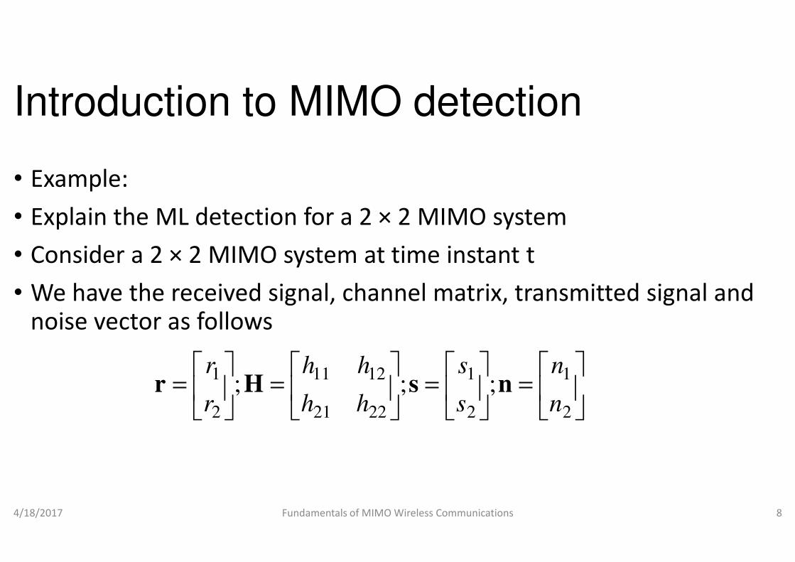
• In general, the decoding complexity increases exponentially
• where NT is the number of transmit antennas and M is the signal
TN
S M=
• where NT is the number of transmit antennas and M is the signal constellation size
• Performance analysis
• Let us try to find the PEP for detecting
• when the signal vector transmitted was
4/18/2017 Fundamentals of MIMO Wireless Communications
( ) (21 Pr Hsyss −=→ obP
Introduction to MIMO detection
In general, the decoding complexity increases exponentially
is the number of transmit antennas and M is the signal
TN
S M=
is the number of transmit antennas and M is the signal
Let us try to find the PEP for detecting s2
when the signal vector transmitted was s1
Fundamentals of MIMO Wireless Communications 12
)2
1
2
2 HsyHs −≤

Introduction to MIMO detection
• Define (it is like your codeword difference matrix)
• Note that
21 ssd −=
hhn 12111
4/18/2017 Fundamentals of MIMO Wireless Communications
=
=
RRR NNN hh
hh
hh
n
n
n
MMM
1
2221
1211
2
1
; Hn
Introduction to MIMO detection
Define (it is like your codeword difference matrix)
TN dhL 1112
Fundamentals of MIMO Wireless Communications 13
=
TTRR
T
T
NNN
N
N
d
d
d
h
h
h
M
L
MO
L
L
2
1
2
222
112
;d

Introduction to MIMO detection
• The PEP can be calculated as
( )
=→0
2
212N
QPHd
ss
• Using Chernoff’s bound, PEP is bounded as
4/18/2017 Fundamentals of MIMO Wireless Communications
02N
( )
−≤→ 21 expP
Hdss
Introduction to MIMO detection
2
bound, PEP is bounded as
Fundamentals of MIMO Wireless Communications 14
0
2
4N
Hd

Introduction to MIMO detection
• When we assume that the first matrix is
• Hd is already a vector, we are trying to find an alternate form of
( ) (CABCvecT ⊗=Q
( ) ( )IABAB vecvec =
• Hd is already a vector, we are trying to find an alternate form of representation
• which will be useful in calculating the average PEP from
• the MGF of a random quadratic form of a complex Gaussian multivariate v
• Using the above identity
4/18/2017 Fundamentals of MIMO Wireless Communications
(vec vec∴ = ⊗Hd d I H
Introduction to MIMO detection
When we assume that the first matrix is I, we have
is already a vector, we are trying to find an alternate form of
) ( )BA vec⊗
( ) ( )AIB vecT ⊗=
is already a vector, we are trying to find an alternate form of
which will be useful in calculating the average PEP from
random quadratic form of a Hermitian matrix A in
Fundamentals of MIMO Wireless Communications 15
) ( ) ( )R
T
Nvec vec∴ = ⊗Hd d I H

Introduction to MIMO detection
• Therefore, the average PEP with respect to
( )
−≤
>→<
2
21
4exp
NE
P
Hd
ss
4/18/2017 Fundamentals of MIMO Wireless Communications
( )
( )( ) ( ) (
⊗
−=
−≤
−≤
0
0
0
4exp
4exp
4exp
N
vec
E
NE
NE
R
TH
NTH
H
dIdH
HdHd Q
Introduction to MIMO detection
Therefore, the average PEP with respect to h is given by
Fundamentals of MIMO Wireless Communications 16
) ( )
⊗ vec
RNT
HI
( ) ( ) ( )R
T
Nvec vec= ⊗ =Hd d I H HdQ

Introduction to MIMO detection
• Using the identity on the Kronecker
( )( )
( )⊗∴
=⊗⊗
*
R NH
NT
IIdd
ACDCBAQ
4/18/2017 Fundamentals of MIMO Wireless Communications
( )( )
( )( )(
−≤
>→<
⊗∴
21
expvec
E
P
R NN
H
ss
IIdd
Introduction to MIMO detection
Kronecker product, we have,
⊗=
⊗
*
RR NT
Idd
BDAC
Fundamentals of MIMO Wireless Communications 17
) ( ) ( ))
⊗
⊗=
0
*
4N
vecR
RR
NTH
N
HIdd
Idd

Introduction to MIMO detection
• Theorem:
• Consider the random quadratic form of a complex Gaussian multivariate =v
4/18/2017 Fundamentals of MIMO Wireless Communications
• The MGF of the y is given as
( ) Hy Quad= =
Av vAv
( ){exp
y
s sM s
=
v vµ A I R A
Introduction to MIMO detection
Consider the random quadratic form of a Hermitian matrix A in
( ),N
CN=
v Vv µ R
Fundamentals of MIMO Wireless Communications 18
{ } ( )1 H
v
v
s s
s
− −
−
v vµ A I R A µ
I R A

Introduction to MIMO detection
• We can show that for a symmetric and positive semi
• and note that h=vect
• In the mgf, if we put s=-1 and µv=0
( )( ) (
( )hRh ,0~ cN
• For and iid Rayleigh fading
4/18/2017 Fundamentals of MIMO Wireless Communications
( )( ) (detexp =− IAhhH
E
0
*
4N
RNT Idd
A⊗
=
( )21 det≤→∴ P ss
+ J. Choi, Optimal Combining & Detection, Cambridge University Press, 2010
Introduction to MIMO detection
We can show that for a symmetric and positive semi-definite matrix A
vect(H) and µv=0
0 in the previous theorem,
)
Rayleigh fading Rh=I
Fundamentals of MIMO Wireless Communications 19
) 1−+ hARI
( ) 1
0
*
4det
−
⊗+
N
RNT
IddI
, Cambridge University Press, 2010.

Introduction to MIMO detection
( )21 det
≤→∴ P ssIII =⊗Q
( )P ≤→∴ ss
• Diversity gain
• From the above equation on the upper bound on PEP
• we can say that the diversity gain of the ML detection is N
4/18/2017 Fundamentals of MIMO Wireless Communications
( )P ≤→∴ 21 ss
Introduction to MIMO detection1
0
*
4
−
⊗
+
RN
T
NI
ddI
RNT
−
+≤*
detdd
I
From the above equation on the upper bound on PEP
we can say that the diversity gain of the ML detection is NR
Fundamentals of MIMO Wireless Communications 20
N
+≤
04det I

Introduction to MIMO detection
• Another alternative MIMO detection technique
• Employ simpler and easy to implement linear detectors
• but they have poorer performance
• Linear sub-optimal detectors• Linear sub-optimal detectors
• In linear detector,
• a linear preprocessor (W) is first applied to the received signal vector
• the estimated symbol is given by
4/18/2017 Fundamentals of MIMO Wireless Communications
rWsH=ˆ
Introduction to MIMO detection
Another alternative MIMO detection technique
Employ simpler and easy to implement linear detectors
but they have poorer performance
) is first applied to the received signal vector
Fundamentals of MIMO Wireless Communications 21
Introduction to MIMO detection
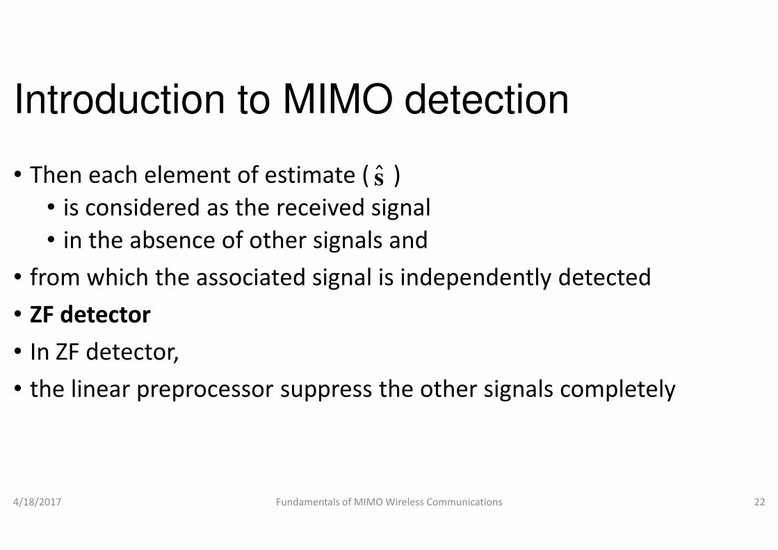
• Then each element of estimate ( )
• is considered as the received signal
• in the absence of other signals and
• from which the associated signal is independently detected
s
• from which the associated signal is independently detected
• ZF detector
• In ZF detector,
• the linear preprocessor suppress the other signals completely
4/18/2017 Fundamentals of MIMO Wireless Communications
Introduction to MIMO detection
Then each element of estimate ( )
is considered as the received signal
in the absence of other signals and
from which the associated signal is independently detected
s
from which the associated signal is independently detected
the linear preprocessor suppress the other signals completely
Fundamentals of MIMO Wireless Communications 22
Introduction to MIMO detection
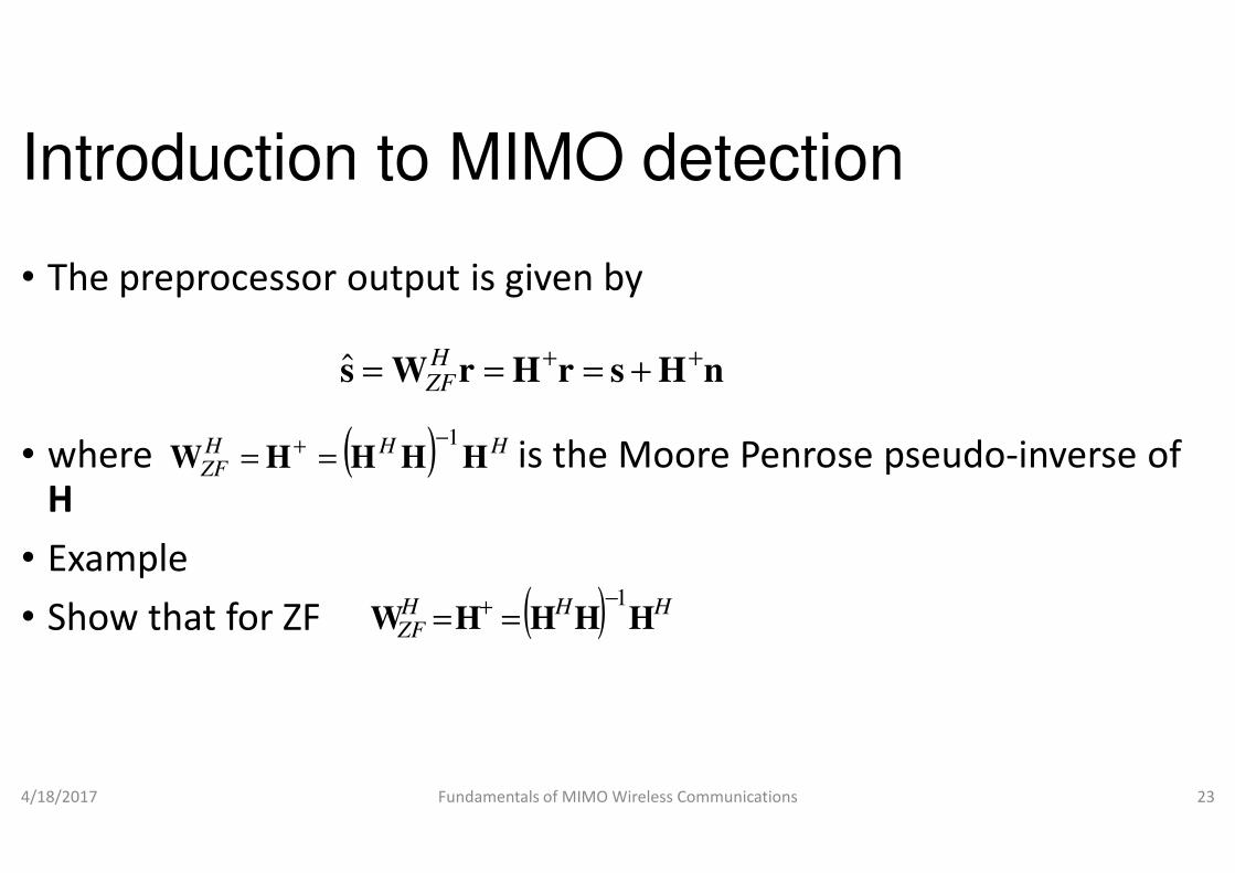
• The preprocessor output is given by
• where is the Moore Penrose pseudo
srHrWs+ === H
ZFˆ
( ) HHH 1−+ ==• where is the Moore Penrose pseudoH
• Example
• Show that for ZF
4/18/2017 Fundamentals of MIMO Wireless Communications
( ) HHHZF HHHHW
1−+ ==
( )HHZF HHHW
1−+ ==
Introduction to MIMO detection
The preprocessor output is given by
where is the Moore Penrose pseudo-inverse of
nHs++
where is the Moore Penrose pseudo-inverse of
Fundamentals of MIMO Wireless Communications 23
HH
1−

Introduction to MIMO detection
• Note that the ZF searches for unconstrained vector
• (not constrained to alphabet S) that
• minimizes the squared Euclidean to the received vector
• This can be done by taking partial derivative
• w.r.t. and setting to 0 as follows
4/18/2017 Fundamentals of MIMO Wireless Communications
2min
arg
Hsr
s
−
∈ TNC
Introduction to MIMO detection
Note that the ZF searches for unconstrained vector
(not constrained to alphabet S) that
minimizes the squared Euclidean to the received vector r as
TNC∈s
This can be done by taking partial derivative
Fundamentals of MIMO Wireless Communications 24
2Hsr −
Introduction to MIMO detection
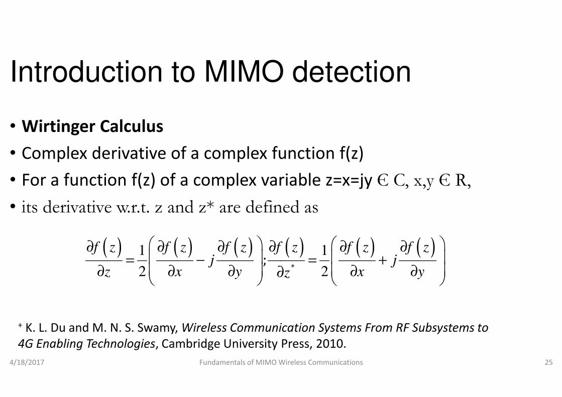
• Wirtinger Calculus
• Complex derivative of a complex function f(z)
• For a function f(z) of a complex variable z=x=
• its derivative w.r.t. z and z* are defined as• its derivative w.r.t. z and z* are defined as
4/18/2017 Fundamentals of MIMO Wireless Communications
( ) ( ) ( )1 1
2 2;
f z f z f z f z f z f zj j
z x y x y
∂ ∂ ∂ ∂ ∂ ∂ = − = + ∂ ∂ ∂ ∂ ∂∂
+ K. L. Du and M. N. S. Swamy, Wireless Communication Systems From RF Subsystems to
4G Enabling Technologies, Cambridge University Press, 2010.
Introduction to MIMO detection
Complex derivative of a complex function f(z)
For a function f(z) of a complex variable z=x=jy Є C, x,y Є R,
. z and z* are defined as. z and z* are defined as
Fundamentals of MIMO Wireless Communications 25
( ) ( ) ( )1 1
2 2*;
f z f z f z f z f z f zj j
z x y x yz
∂ ∂ ∂ ∂ ∂ ∂ = − = + ∂ ∂ ∂ ∂ ∂∂
Wireless Communication Systems From RF Subsystems to
, Cambridge University Press, 2010.
Introduction to MIMO detection
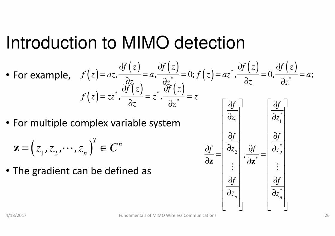
• For example,
• For multiple complex variable system
( )( ) (
( )( )
* *
, , ; , , ;
, ,
f z f z f z f zf z az a f z az a
z zz zf z f z
f z zz z zz
∂ ∂ ∂ ∂= = = = = =
∂ ∂∂ ∂∂ ∂
= = =∂
• For multiple complex variable system
• The gradient can be defined as
4/18/2017 Fundamentals of MIMO Wireless Communications
( )1 2, , ,
Tn
nz z z C= ∈z L
Introduction to MIMO detection
For multiple complex variable system
( )( )
( ) ( )
( )0 0*
* *
*
, , ; , , ;
, ,
f z f z f z f zf z az a f z az a
z zz zf z f z
f z zz z zz
∂ ∂ ∂ ∂= = = = = =
∂ ∂∂ ∂∂ ∂
= = =∂
1
*
f f
z z
∂ ∂
∂ ∂ For multiple complex variable system
Fundamentals of MIMO Wireless Communications 26
1 1
2 2
*
*
*
*
,
n n
z z
f f
z zf f
f f
z z
∂ ∂
∂ ∂ ∂ ∂∂ ∂ = =
∂ ∂ ∂ ∂ ∂ ∂
z zM M

Introduction to MIMO detection
• Similarly,( )
( )
( )( )
*
, ,
, ,
T T
T H
f ff
f ff
∂ ∂= = = =
∂
∂ ∂= = = =
z zz c z z c c 0
z
z zz c z z c 0 c
4/18/2017 Fundamentals of MIMO Wireless Communications
( )( )
( )
( )1 2
*
* *
, ,
, , ;
, , ,
T H
H T T
Tn
n
f ff
f
c c c C
∂ ∂= = = =
∂
∂ ∂= = = =
= ∈
z zz c z z c 0 c
z
z z Mz z Mz M z Mz
c L
Introduction to MIMO detection
( )
) ( )
*
*
, ,
, ,
f f
f f
∂ ∂= = = =
∂
∂ ∂= = = =
z zz c z z c c 0
z
z zz c z z c 0 c
Fundamentals of MIMO Wireless Communications 27
) ( )
( ) ( )
*
* *
*
, ,
, , ;H T T
f f
f f
∂ ∂= = = =
∂
∂ ∂= = = =
∂ ∂
z zz c z z c 0 c
z z
z zz z Mz z Mz M z Mz
z z
Introduction to MIMO detection
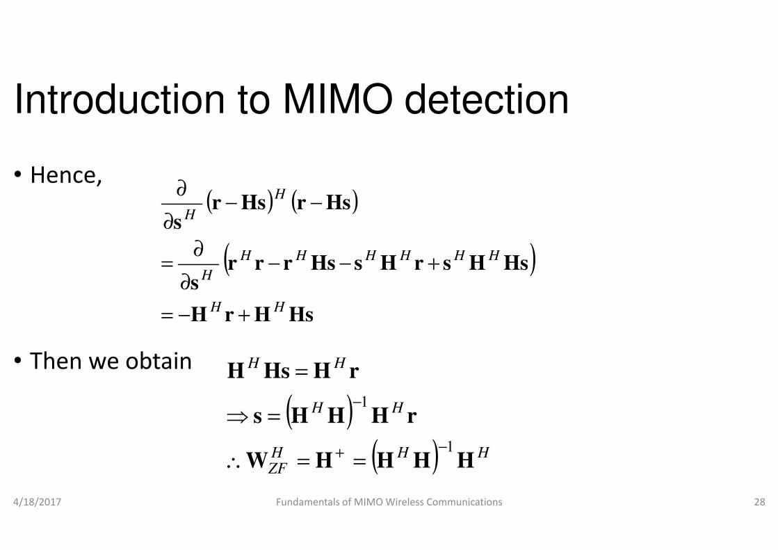
• Hence,( ) ( )
( HsHsrrrs
HsrHsrs
HHH
H
H
H
−−∂
∂=
−−∂
∂
• Then we obtain
4/18/2017 Fundamentals of MIMO Wireless Communications
(
HsHrH
sHH
H
+−=
∂
( )(H
ZF
H
HH
HHW
HHHs
rHHsH
1
+
−
==∴
=⇒
=
Introduction to MIMO detection
)HsHsrHHHH +
Fundamentals of MIMO Wireless Communications 28
)
) HH
H
HHH
r
1−
Introduction to MIMO detection
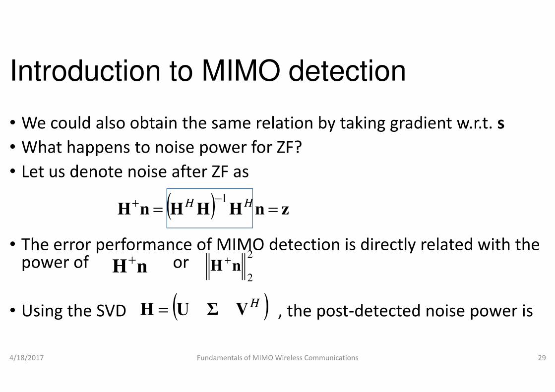
• We could also obtain the same relation by taking gradient
• What happens to noise power for ZF?
• Let us denote noise after ZF as
( )−+ HH 1
• The error performance of MIMO depower of or
• Using the SVD , the post
4/18/2017 Fundamentals of MIMO Wireless Communications
( ) nHHHnH ==−+ HH 1
nH+ 2
2nH
+
( )HVΣUH =
Introduction to MIMO detection
We could also obtain the same relation by taking gradient w.r.t. s
What happens to noise power for ZF?
detection is directly related with the
Using the SVD , the post-detected noise power is
Fundamentals of MIMO Wireless Communications 29
z=

Introduction to MIMO detection
( ) (
22
22
22
2
12
2
HHH
HH
HH
===
∑=∑∑=
∑==
−
−
xxxQxQxQx
VnUVVV
VnHHHz
Q
4/18/2017 Fundamentals of MIMO Wireless Communications
{ } {
( ){ } {
2min
2
12
2
11
2
2
12
2
2
2
2
2
σ
σ
σ
σ n
N
i i
n
HH
H
HHH
T
trEtr
trEEE
≈=
∑=∑∑=
=
∑=∴
===
∑=
−−
−
UUnn
nUz
xxxQxQxQxQ
Introduction to MIMO detection
)
2
21
2
2
1
H
HH
∑
∑
−
−
nU
nUVV
Fundamentals of MIMO Wireless Communications 30
( )}
} { }2222
11
2
2
σ nn
HH
tr
tr
∑=∑
∑∑
−−
−−
σ
UnnU

Introduction to MIMO detection
• Looking at the above equation, for not well behaved channel matrix,
• is very small and hence will be a large number
• Main hurdle of linear detector:
2minσ 2
min
2
σ
σn
• Main hurdle of linear detector:
• noise power is getting amplified due to
• application of the linear preprocessor (
• for ill behaved channel matrix
• Possible solution: Employ techniques like lattice reduction (LR)
4/18/2017 Fundamentals of MIMO Wireless Communications
Introduction to MIMO detection
Looking at the above equation, for not well behaved channel matrix,
is very small and hence will be a large number
noise power is getting amplified due to
linear preprocessor (W)
Possible solution: Employ techniques like lattice reduction (LR)
Fundamentals of MIMO Wireless Communications 31

Introduction to MIMO detection
• SINR for ZF
• Post-detected noise :
• is a zero mean circular symmetric complex Gaussian with covariance matrix given by
( HHnH =+ H
matrix given by
4/18/2017 Fundamentals of MIMO Wireless Communications
( ) ( ) (
( ) ( ) ( )
1
1 1 1 12 2
H H H H H H H H H
zz
H H
H H H H H
n n
E E E
σ σ
−
− − − −
= = = = = =
R zz H H H nn H H H H H H nn H H H
H H H H H H H H H H
Introduction to MIMO detection
is a zero mean circular symmetric complex Gaussian with covariance
) znHH =− H1
Fundamentals of MIMO Wireless Communications 32
) ( ) ( ) ( )
( )
1 1 1
1 1 1 12 2
H H
H H H H H H H H H
H H
H H H H H
n n
E E E
σ σ
− − −
− − − −
= = = = = =
R zz H H H nn H H H H H H nn H H H
H H H H H H H H H H

Introduction to MIMO detection
• Then we can obtain the kth diagonal element of
( ) ( )Hnkk
=
−12,
HHRzz σ
• Consider the received signal in the i
4/18/2017 Fundamentals of MIMO Wireless Communications
[ iiii hhhr = 2,1, L
Introduction to MIMO detection
diagonal element of aszzR
kk
Consider the received signal in the ith antenna given by
Fundamentals of MIMO Wireless Communications 33
] iNi nhT
+s,
Introduction to MIMO detection
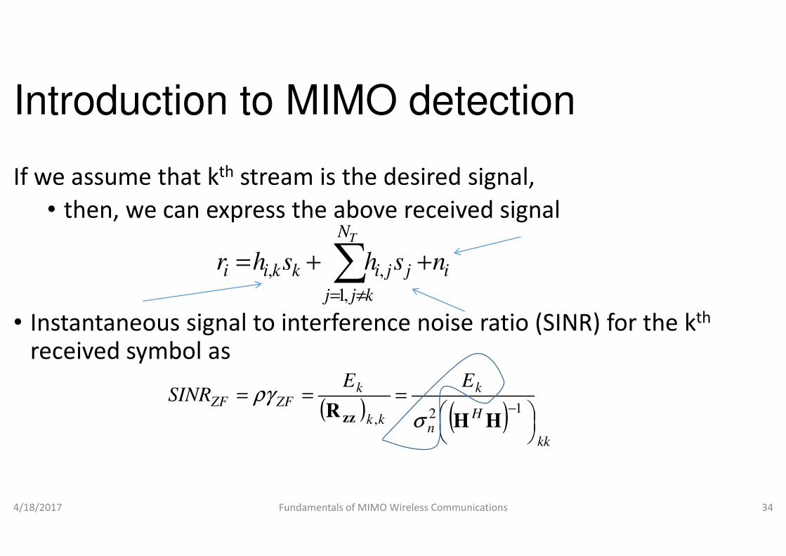
If we assume that kth stream is the desired signal,
• then, we can express the above received signal
∑+=TN
jikkii hshr ,,
• Instantaneous signal to interference noise ratio (SINR) for the received symbol as
4/18/2017 Fundamentals of MIMO Wireless Communications
∑≠= kjj
jikkii
,1
,,
( )kk
kZFZF
ESINR ==
,R zz
ργ
Introduction to MIMO detection
stream is the desired signal,
then, we can express the above received signal
+ ij ns
Instantaneous signal to interference noise ratio (SINR) for the kth
Fundamentals of MIMO Wireless Communications 34
ij
( )kk
Hn
kE
=−12
HHσ

Introduction to MIMO detection
• where is the mean SNR
• SINR of ZF has been shown+ to be a Chi
• is distributed with degrees
ρ
γ χ• is distributed with degrees
4/18/2017 Fundamentals of MIMO Wireless Communications
ZFγ
( )2 1R T
N Nχ
− +
+ M. Rupp, C. Mecklenbrauker and G. Gritsch, “High diversity with simple space
block-codes and linear receivers,” in Proc. IEEE GLOBECOM
Introduction to MIMO detection
to be a Chi-square RV
is distributed with degrees-of-freedom( )− +is distributed with degrees-of-freedom
Fundamentals of MIMO Wireless Communications 35
( )2 1R T
N N− +
, “High diversity with simple space-time
IEEE GLOBECOM, 2003, pp. 302-306.

Introduction to MIMO detection
• Example
• Find the outage probability of ZF
• Consider the separate spatial encoding case
• the data is demultiplexed (DMUX) to several sub• the data is demultiplexed (DMUX) to several sub
• each one of them separately encoded and
• feed to the corresponding transmitting antenna and
• sent through the channel
4/18/2017 Fundamentals of MIMO Wireless Communications
+ A. Hedayat and A. Nostrania, “Outage and diversity of linear receivers in flat
MIMO channels,” IEEE Trans. Signal Processing, vol. 55, no. 12, Dec. 2007, pp. 5868
5873.
Introduction to MIMO detection
Consider the separate spatial encoding case+,
(DMUX) to several sub-streams, (DMUX) to several sub-streams,
each one of them separately encoded and
feed to the corresponding transmitting antenna and
Fundamentals of MIMO Wireless Communications 36
, “Outage and diversity of linear receivers in flat-fading
, vol. 55, no. 12, Dec. 2007, pp. 5868-

Introduction to MIMO detection
• If any one of the data sub-stream is for each sub-streams),
• the whole MIMO system is in outage
• The mutual information between • The mutual information between
• the kth transmitted symbol vector and
• kth estimated symbol vector at the output of the ZF detector
4/18/2017 Fundamentals of MIMO Wireless Communications
+ J. Choi, Optimal Combining & Detection, Cambridge University Press, 2010
ks
( ) (kk SINRI += 1logˆ; 2ss
Introduction to MIMO detection
is in outage (assume equal data rate
the whole MIMO system is in outage
transmitted symbol vector and
estimated symbol vector at the output of the ZF detector+
Fundamentals of MIMO Wireless Communications 37
, Cambridge University Press, 2010.
ks
) ( )ZFZFSINR ργ+= 1log2
Introduction to MIMO detection
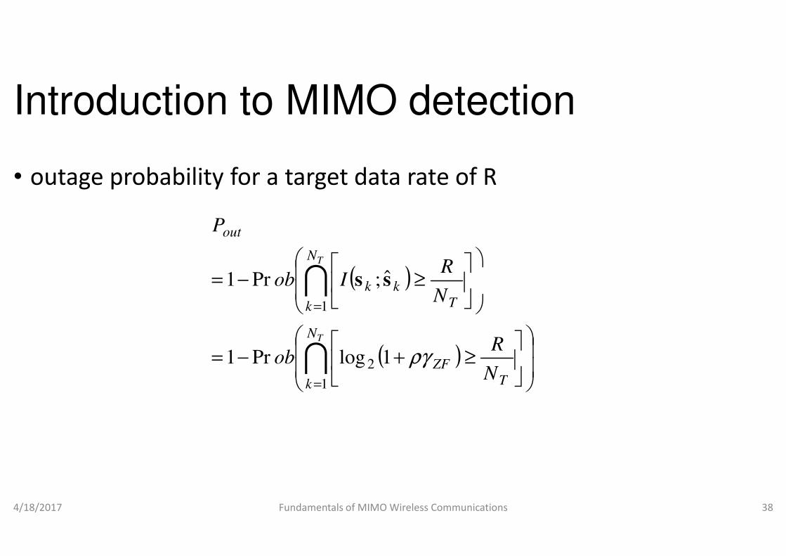
• outage probability for a target data rate of R
(
−= ITN
out
Iob
P
ˆ;Pr1 ss
4/18/2017 Fundamentals of MIMO Wireless Communications
(
(
−=
−=
=
=
I
I
TN
k
k
kk
ob
Iob
1
2
1
1logPr1
ˆ;Pr1 ss
Introduction to MIMO detection
outage probability for a target data rate of R
)
≥R
Fundamentals of MIMO Wireless Communications 38
)
)
≥+
≥
T
ZF
T
k
N
R
N
ργ

Introduction to MIMO detection• Assume independent and equal sub
( ZF
out
ob
P
+−= ργ1logPr1 2
• For outage probabilities for sub-channels are small, we have,
4/18/2017 Fundamentals of MIMO Wireless Communications
( )
(
+=
<+≈
ZFT
ZF
out
obN
ob
P
ργ
ργ
1logPr
1logPr
2
2
Introduction to MIMO detectionAssume independent and equal sub-channel outage probabilities
)TN
T
ZFN
R
≥
channels are small, we have,
Fundamentals of MIMO Wireless Communications 39
T
)
<
<
T
ZF
N
R
N
R
N
RT

Introduction to MIMO detection• Since is distributed , outage probability from the CDF ZF
γ ( )2 1R T
N Nχ
− +
−
<≈12
PrN
R
ZFT
out
obN
P
T
ργ
4/18/2017 Fundamentals of MIMO Wireless Communications
−= ∑=
−
− 1+N-N
1
12
TR
1
i
T eN
TN
R
ρ
Introduction to MIMO detectionSince is distributed , outage probability from the CDF
− 1iR
Fundamentals of MIMO Wireless Communications 40
( )
−
−
− 1
!1
12
i
N
R
i
T
ρ
Introduction to MIMO detection
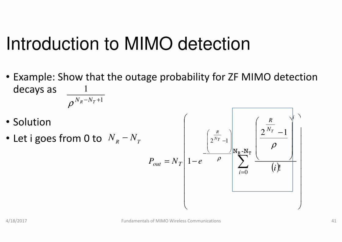
• Example: Show that the outage probability for ZF MIMO detection decays as
• Solution
1
1+− TR NNρ
• Solution
• Let i goes from 0 to
4/18/2017 Fundamentals of MIMO Wireless Communications
R TN N−
=outP
Introduction to MIMO detection
Example: Show that the outage probability for ZF MIMO detection
iR
Fundamentals of MIMO Wireless Communications 41
( )
−
− ∑=
−
− N-NTR
0
12
!
12
1
i
N
R
Ti
eN
T
TN
R
ρ
ρ

Introduction to MIMO detection
• Using the infinite series expansion of exponential function, we get,
−
− 212 TN
R
TN
R
4/18/2017 Fundamentals of MIMO Wireless Communications
−=
−
−
−
212
1Tout eeNP
TNTN
ρρ
Introduction to MIMO detection
Using the infinite series expansion of exponential function, we get,
−
−1
12
i
N
R
T
ρ
Fundamentals of MIMO Wireless Communications 42
( )
− ∑
∞
+=
−
N-NTR
1
1
!i
i
ρ

Introduction to MIMO detection
−12
2N
TN
R
• Pout
4/18/2017 Fundamentals of MIMO Wireless Communications
= ∑
∞
+=
−
1N-N TRi
T eN ρ
Introduction to MIMO detection
−1
i
N
R
T
ρ
Fundamentals of MIMO Wireless Communications 43
( )
!i
ρ
Introduction to MIMO detection
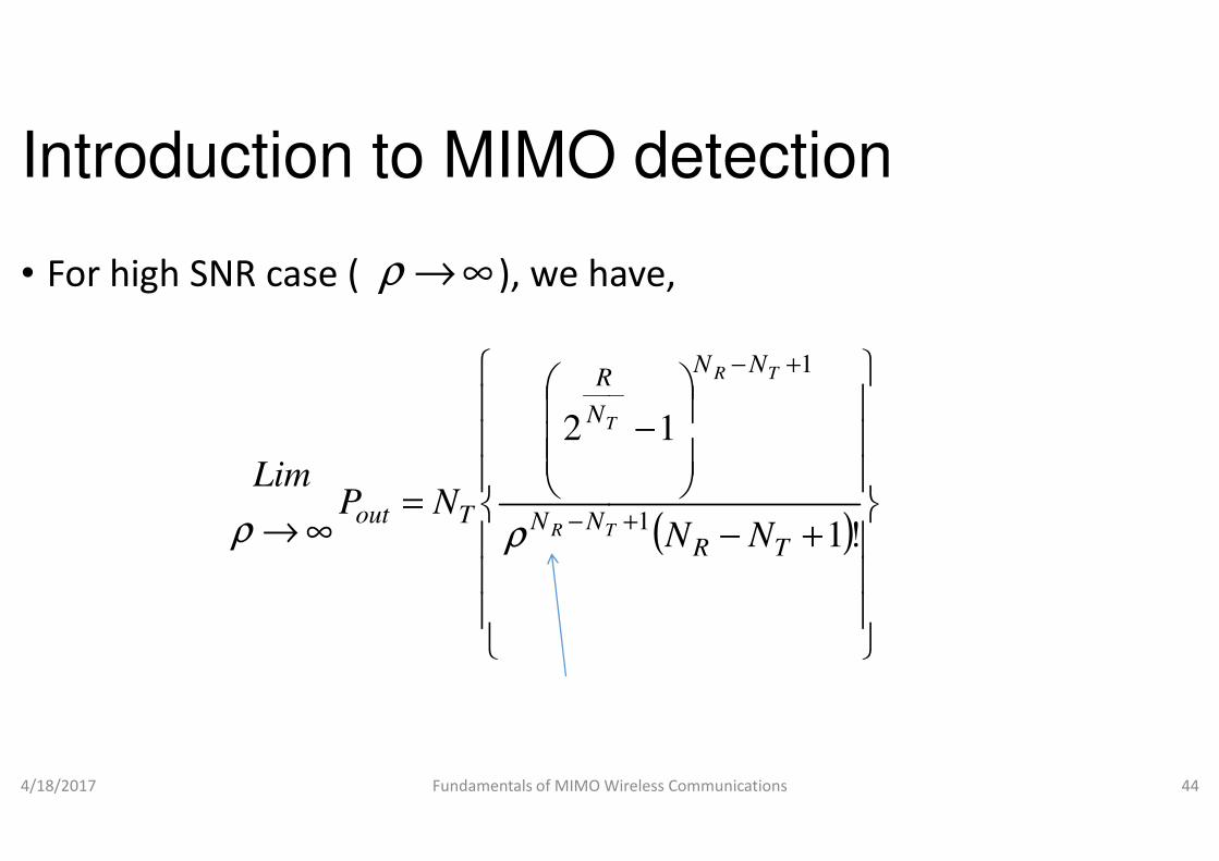
• For high SNR case ( ), we have, ∞→ρ
2
N
R
T
4/18/2017 Fundamentals of MIMO Wireless Communications
=
∞→ −
2
NNTout NPLim
TR
T
ρρ
Introduction to MIMO detection
For high SNR case ( ), we have,
−
+−
1
1NNR TR
T
Fundamentals of MIMO Wireless Communications 44
( )
+−
−
+!1
1
1TR NNT
T

Introduction to MIMO detection
• Hence the diversity gain is
• Performance analysis
• The post-detection SINR of ZF detector is given by
R TN N− +
• Assume hi is the ith row vector of H
• hi has complex multivariate normal distribution
4/18/2017 Fundamentals of MIMO Wireless Communications
( )Hn
kZFZF
ESINR
12
==−
HHσργ
Introduction to MIMO detection
detection SINR of ZF detector is given by
1R T
N N− +
H, then,
has complex multivariate normal distribution
Fundamentals of MIMO Wireless Communications 45
T
kk
Nk ,,2,1;
,
1L=
( )iiNCi
TN ∑,~ µh
Introduction to MIMO detection
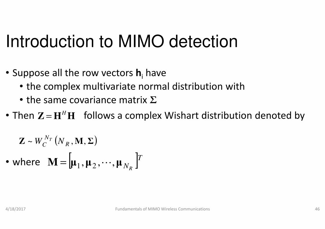
• Suppose all the row vectors hi have
• the complex multivariate normal distribution with
• the same covariance matrix Σ
• Then follows a complex H=Z H H• Then follows a complex
• where
4/18/2017 Fundamentals of MIMO Wireless Communications
H=Z H H
( )ΣMZ ,,~ RN
C NW T
[ ]TNRµµµM ,,, 21 L=
Introduction to MIMO detection
have
the complex multivariate normal distribution with
Then follows a complex Wishart distribution denoted byThen follows a complex Wishart distribution denoted by
Fundamentals of MIMO Wireless Communications 46

Introduction to MIMO detection
• For M=0, we have central complex
• M≠0, then we have non-central complex
• One can also convert
• non-central complex Wishart to central complex • non-central complex Wishart to central complex distribution
• The non-central complex Wishart distribution can be approximated
• by central complex Wishart distribution as
4/18/2017 Fundamentals of MIMO Wireless Communications
( )ΣZ RN
C NW T ;ˆ,~
Introduction to MIMO detection
, we have central complex Wishart distribution and
central complex Wishart distribution
to central complex Wishartto central complex Wishart
distribution can be approximated
distribution as
Fundamentals of MIMO Wireless Communications 47
) MMΣΣH
RN
1ˆ; +=
Introduction to MIMO detection
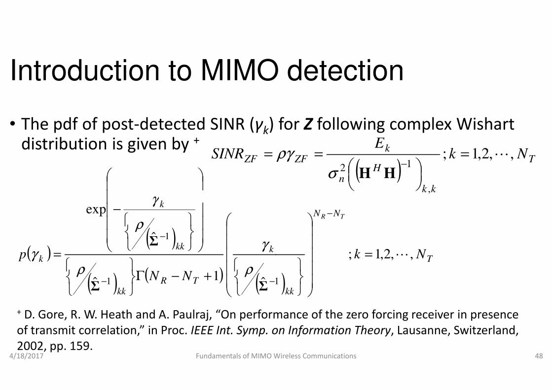
• The pdf of post-detected SINR (γk) for distribution is given by +
γ
ZFSINR =
4/18/2017 Fundamentals of MIMO Wireless Communications
( )( )
( ) ( ) (
k
TRkk
kk
k
k
NN
p
ˆ1
ˆ
ˆ
exp
11
1
+−Γ
−
=
−−
−
ΣΣ
Σ
ρ
γ
ρ
ρ
γ
γ
+ D. Gore, R. W. Heath and A. Paulraj, “On performance of the zero forcing receiver in presence
of transmit correlation,” in Proc. IEEE Int. Symp. on Information Theory
2002, pp. 159.
Introduction to MIMO detection
) for Z following complex Wishart
( )T
kk
Hn
kZF Nk
E,,2,1;
,
12
L=
=−
HHσργ
Fundamentals of MIMO Wireless Communications 48
)T
NN
kk
Nk
TR
,,2,1;
1
L=
−
, “On performance of the zero forcing receiver in presence
. on Information Theory, Lausanne, Switzerland,

Introduction to MIMO detection
• Hence CDF is given by
,1
+− TR NN
ργ
• where is the mean SNR
4/18/2017 Fundamentals of MIMO Wireless Communications
( )( −Γ
=TR
kNN
P
ρ
γ
2n
kE
σρ =
Introduction to MIMO detection
( )
k
ρ
γ
Fundamentals of MIMO Wireless Communications 49
( ))1
ˆ 1
+
−
T
kkΣ
ρ
Introduction to MIMO detection
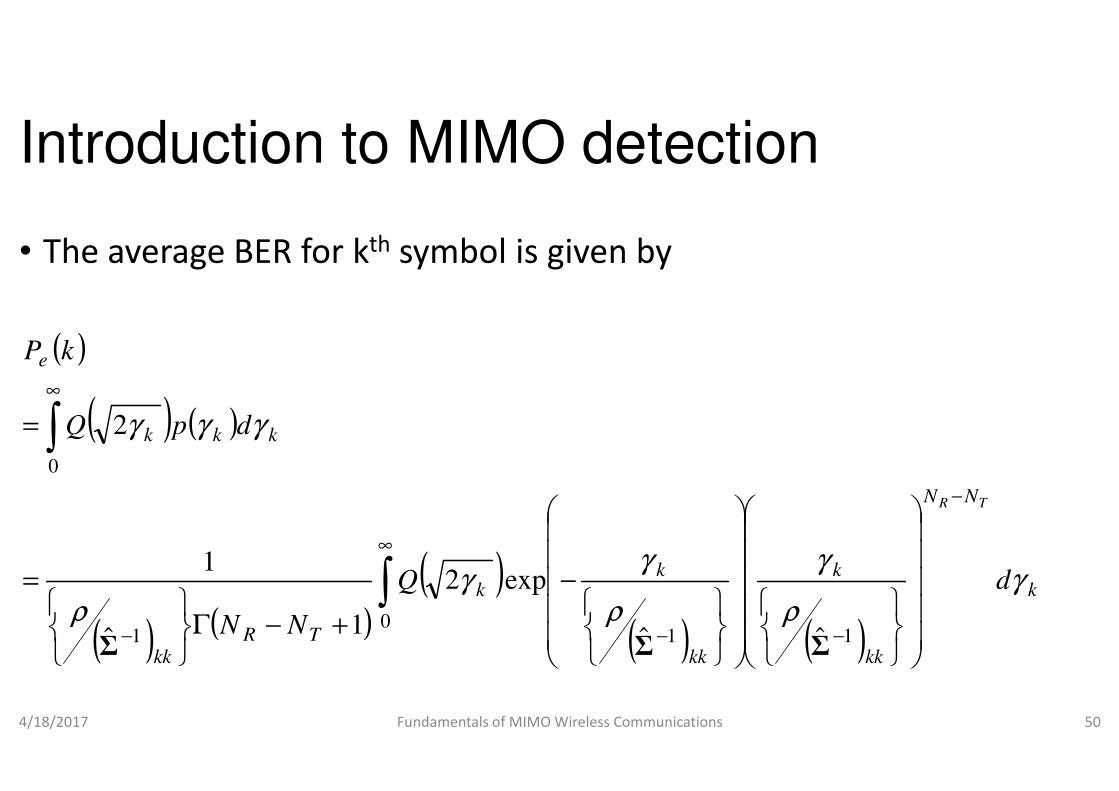
• The average BER for kth symbol is given by
( )
( ) ( )
e kP
∞
4/18/2017 Fundamentals of MIMO Wireless Communications
( ) ( )
( ) ( )( )k
TRkk
kkk
Q
NN
dpQ
γρ
γγγ
∞
−
∞
+−Γ
=
=
∫
∫
01
0
exp2
1ˆ
1
2
Σ
Introduction to MIMO detection
symbol is given by
Fundamentals of MIMO Wireless Communications 50
( ) ( )k
NN
kk
k
kk
kd
TR
γρ
γ
ρ
γ
−
−−
−
11 ˆˆ ΣΣ

Introduction to MIMO detection
• Let , then( )
= −kk
k 1Σ
ργγ
( )( ) (
ργQNN
kPe
∞
+−Γ= ∫ ˆ
21
1
Σ
4/18/2017 Fundamentals of MIMO Wireless Communications
( ) (NN TR
e
+−Γ ∫ ˆ1
0Σ
( )( ) ( )1
0
, ,m
q mqI p q m Q p e d
m
γγ γ γ∞
− −=Γ
∫
2
=p
Introduction to MIMO detection
) ( )( ) γγγ dTR NN −− −
exp1Σ
Fundamentals of MIMO Wireless Communications 51
)kk−
1
Σ
1q mI p q m Q p e d
γγ γ γ− −
( ) 1,1,ˆ 1 +−==
− TRkk
NNmqΣ
ρ
Introduction to MIMO detection
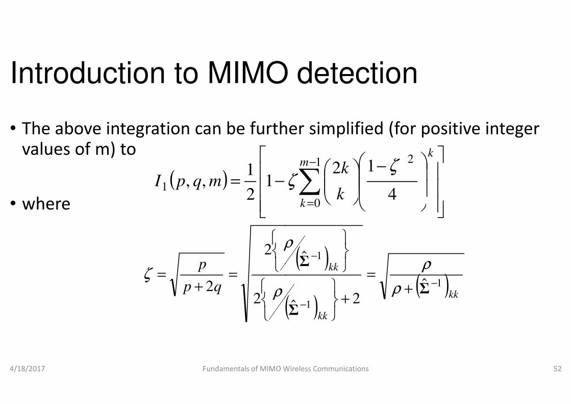
• The above integration can be further simplified (for positive integer values of m) to
• where
( )
−=1 12
1,, mqpI
• where
4/18/2017 Fundamentals of MIMO Wireless Communications
(qp
p
2
2
2
=+
=ρ
ρ
ζ
2
Introduction to MIMO detection
The above integration can be further simplified (for positive integer
−
∑
−
=
1
0
2
4
12m
k
k
k
k ζζ
Fundamentals of MIMO Wireless Communications 52
( )
( )( )kk
kk
kk
1
1
1
ˆ2ˆ
ˆ
−
−
−
+=
+
Σ
Σ
Σ
ρ
ρ
ρ
=04
kk

Introduction to MIMO detection
• Therefore, average BER for symbol k is simply
• Hence we need to find the
( ) ( )
= − ,1,ˆ
2 11 Rkk
e NIkPΣ
ρ
( )1ˆ −• Hence we need to find the
• Let us consider i.i.d. Rayleigh fading MIMO channel
4/18/2017 Fundamentals of MIMO Wireless Communications
( ) 1ˆ
ˆ
0
1 =⇒
==∴
=
−kk
NTI
Σ
ΣΣ
MQ
( )kk1ˆ −
Σ
Introduction to MIMO detection
Therefore, average BER for symbol k is simply
+− 1TR N
. Rayleigh fading MIMO channel
Fundamentals of MIMO Wireless Communications 53

Introduction to MIMO detection
• Therefore, average BER for symbol k is
• MMSE detector
( ) (12 1 1, ,
e R TP k I N Nρ= − +
• MMSE detector
• As we have seen for ZF, noise was getting enhanced
• even if the spatial interference was removed
• MMSE detector minimizes the mean
• of the spatial interference plus noise
4/18/2017 Fundamentals of MIMO Wireless Communications
Introduction to MIMO detection
Therefore, average BER for symbol k is
)2 1 1, ,e R T
P k I N N= − +
As we have seen for ZF, noise was getting enhanced
even if the spatial interference was removed
MMSE detector minimizes the mean-square value
of the spatial interference plus noise
Fundamentals of MIMO Wireless Communications 54
Introduction to MIMO detection
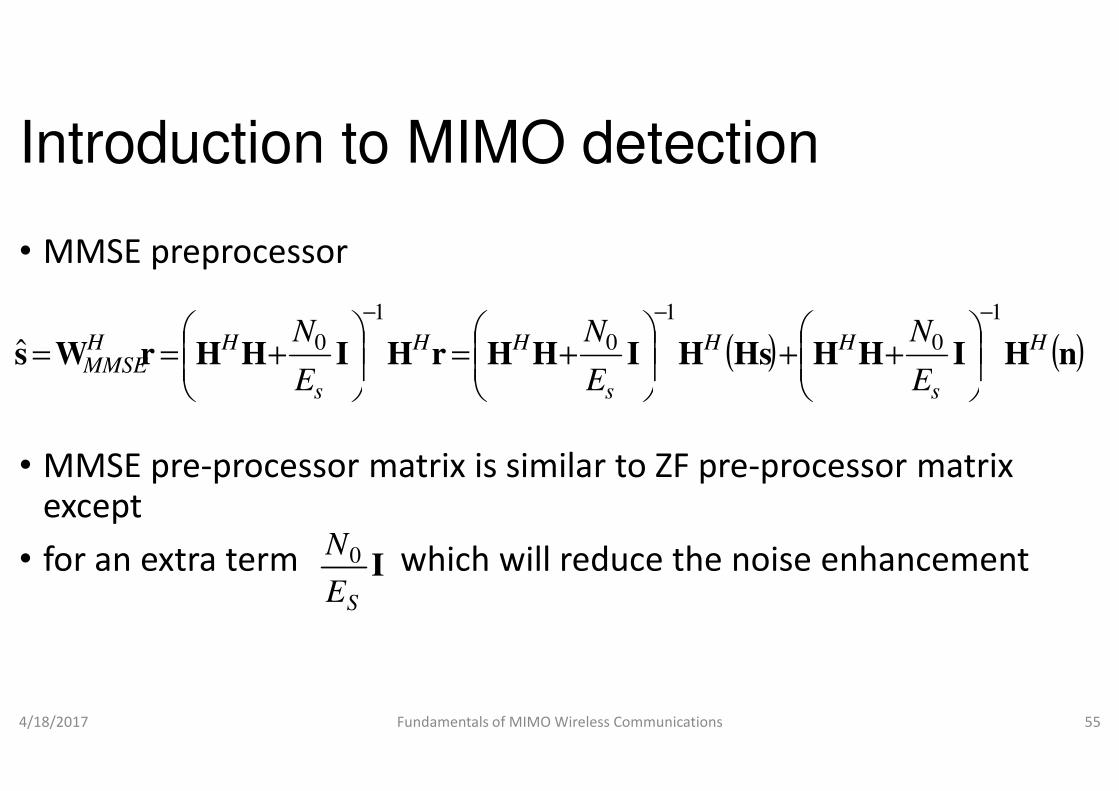
• MMSE preprocessor
HHrHIHHrWs HH
s
HHMMSE
E
N1
0ˆ
−
+=
+==
• MMSE pre-processor matrix is similar to ZF preexcept
• for an extra term which will reduce the noise enhancement
4/18/2017 Fundamentals of MIMO Wireless Communications
sE
ISE
N0
Introduction to MIMO detection
( ) ( )nHIHHHsHI H
s
HH
s E
N
E
N1
0
1
0
−−
++
+
processor matrix is similar to ZF pre-processor matrix
for an extra term which will reduce the noise enhancement
Fundamentals of MIMO Wireless Communications 55
ss EE

Introduction to MIMO detection
• Show that
• Solution
• In MMSE detector, one tries to minimize
( 22 += Hs
Hs
HMMSE HHHW σσσ
• In MMSE detector, one tries to minimize
• the mean square error between the
4/18/2017 Fundamentals of MIMO Wireless Communications
min
arg
rW
s ∈ ×
H
NN
E
C RT
Introduction to MIMO detection
In MMSE detector, one tries to minimize
) 12 −
TNn Iσ
In MMSE detector, one tries to minimize
the actual signal and detected signal
Fundamentals of MIMO Wireless Communications 56
2
sr −

Introduction to MIMO detection
• This can be done by taking partial derivative
• w.r.t. W and setting to 0
( )(WsrW
−
∂ HHtrE
4/18/2017 Fundamentals of MIMO Wireless Communications
( )(
({[(
(
srrr
rr
RRW
RWWRWW
WWrrWW
WsrWW
−=
−∂
∂=
−∂
∂=
−
∂
H
HH
HH
HH
trE
trE
Introduction to MIMO detection
This can be done by taking partial derivative 2
srW −HE
)sr −
HH
Fundamentals of MIMO Wireless Communications 57
)
)}])
)sssrrs RWRR
ssWsrrsW
sr
+−
+−
−
HHHH
H

Introduction to MIMO detection
• Hence,
• Assuming noise vector and signal vector are independent
1−= rrsrRRWHMMSE
Hs
HR HHRHHR nnssrr
2σ +=+=
• Therefore,
4/18/2017 Fundamentals of MIMO Wireless Communications
Hs
HR HHR sssr
2σ==
( 222 +=TNn
Hs
Hs
HMMSE IHHHW σσσ
Introduction to MIMO detection
Assuming noise vector and signal vector are independent
RTT NnNsNn IRIRI nnss222 ,; σσσ ==+
Fundamentals of MIMO Wireless Communications 58
RTT
) 1−
T

Introduction to MIMO detection
• Example
• What happens to noise power for MMSE?
• Let us denote noise after MMSE as
• Using SVD of H+ as , we have,
4/18/2017 Fundamentals of MIMO Wireless Communications
HIHH
+
−
s
H
E
N1
0
HVΣUH =
Introduction to MIMO detection
What happens to noise power for MMSE?
Let us denote noise after MMSE as
as , we have,
Fundamentals of MIMO Wireless Communications 59
( ) znH =H

Introduction to MIMO detection
2 21 1
20 0
2
2 2
H H H H
s s
N N
E E
− −
= + = +
z H H I H n V
z2
2∴
4/18/2017 Fundamentals of MIMO Wireless Communications
( ) ∑=−−
VVΣ11 H
Q
V
V
z
s
H
E
N 0
2
+∑=
+∑=
∴
Introduction to MIMO detection
2 21 1
20 0
2 2
H H H H
s s
N N
E E
− −
= + = +
z H H I H n VΣ V I VΣU n
Fundamentals of MIMO Wireless Communications 60
( )
( )nUΣ
nUVΣ
H
s
HH
sE
N
1
10
1
10
−
−
−
−

Introduction to MIMO detection
• Since the multiplication of a unitary matrix do not change the Frobenius norm, we have
z2
2
• We also know that,
4/18/2017 Fundamentals of MIMO Wireless Communications
( )nUΣH
sE
N1
10
−
−
+∑=
( ) ( ) BBBBB == HHTrTr
Introduction to MIMO detection
Since the multiplication of a unitary matrix do not change the
Fundamentals of MIMO Wireless Communications 61
)
2
2

Introduction to MIMO detection
( )1
210
2
1 1
1 10 0
s
H H
s s
NE E
E
N NE tr
E E
−
−
− −
− −
= +
= + +
z Σ Σ U n
Σ Σ U nn U
4/18/2017 Fundamentals of MIMO Wireless Communications
(1 1
1 10 0
2
10
0
s s
H H
s s
s
E E
N Ntr E
E E
Ntr N
E
− −
− −
−
−
= + +
= +
Σ Σ U nn U
Σ Σ
Introduction to MIMO detection2
2
1 1
1 10 0
H
H H
s s
N N
E E
− −
− −
= + +
U n
U nn U Σ Σ
Fundamentals of MIMO Wireless Communications 62
)1 1
1 10 0
s s
H H
s s
E E
N N
E E
− −
− −
= + +
U nn U Σ Σ
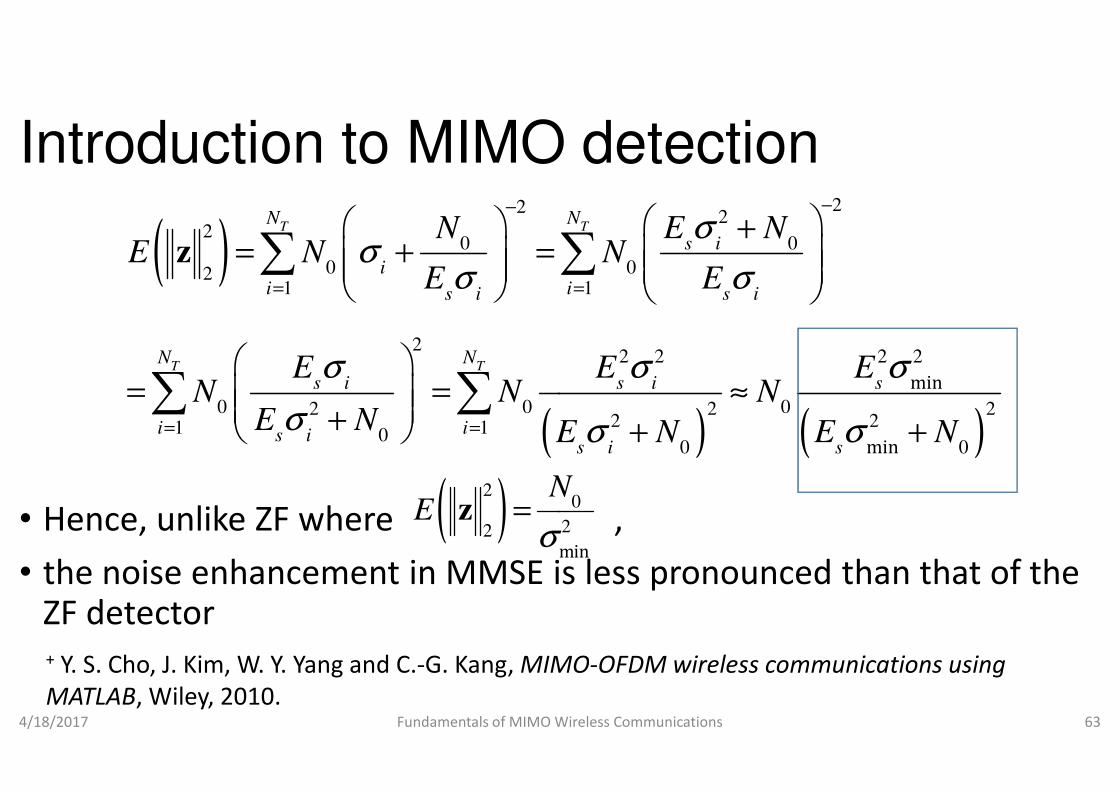
Introduction to MIMO detection
( )
(
2
20 0
0 021 1
2
0 0 0
T T
T T
N N
ii is i s i
N N
s i s i s
N E NE N N
E E
E E EN N N
σσ σ
σ σ σ
−
= =
= + =
= = ≈
∑ ∑
∑ ∑
z
• Hence, unlike ZF where ,
• the noise enhancement in MMSE is ZF detector
4/18/2017 Fundamentals of MIMO Wireless Communications
(0 0 02 2 2
1 10i is i
N N NE N E N E Nσ= =
= = ≈ + ∑ ∑
( )2
2min
NE
σ=z
+ Y. S. Cho, J. Kim, W. Y. Yang and C.-G. Kang, MIMO
MATLAB, Wiley, 2010.
Introduction to MIMO detection
) ( )
22
0 0
0 01 1
2 2 2 2
0 0 0
min
min
T TN N
s i
i is i s i
s i s i s
N E NE N N
E E
E E EN N N
σ
σ σ
σ σ σ
−
= =
+= + =
= = ≈
∑ ∑
Hence, unlike ZF where ,
E is less pronounced than that of the
Fundamentals of MIMO Wireless Communications 63
) ( )0 0 02 2 2
2 2
0 0
min
mins i s
N N N
E N E Nσ σ= = ≈
+ +
0
2
min
N
σ
MIMO-OFDM wireless communications using

Introduction to MIMO detection• Performance analysis
• In linear detector, a linear preprocessor (received signal vector
rWs H=ˆ
• Then we can do individual detection of
• Without loss of generality, let us assume that we are detecting
4/18/2017 Fundamentals of MIMO Wireless Communications
rWs H=ˆ
1ˆ ,k
s k =
Introduction to MIMO detection
In linear detector, a linear preprocessor ( W) is first applied to the
( ) 1 2
H
H
N
=
W w w wL
Then we can do individual detection of
Without loss of generality, let us assume that we are detecting
Fundamentals of MIMO Wireless Communications 64
s
( ) 1 2T
N =
W w w wL

Introduction to MIMO detection
• Then
• One may show that
nwhwrwHHH
ss 111111 +==1 1 11 12 1
= =h w
• One may show that
• The conditional error probability (CEP) for sub
4/18/2017 Fundamentals of MIMO Wireless Communications
( )21 ,0~ nCH
N σnw
= 12 hw
HQCEP
Introduction to MIMO detection
11
21
1 1 11 12 1
1
;R
H
N
N
h
h
w w w
h
= =
h wM L
The conditional error probability (CEP) for sub-channel 1 is given by
Fundamentals of MIMO Wireless Communications 65
1h
1
;
RN
h
Introduction to MIMO detection
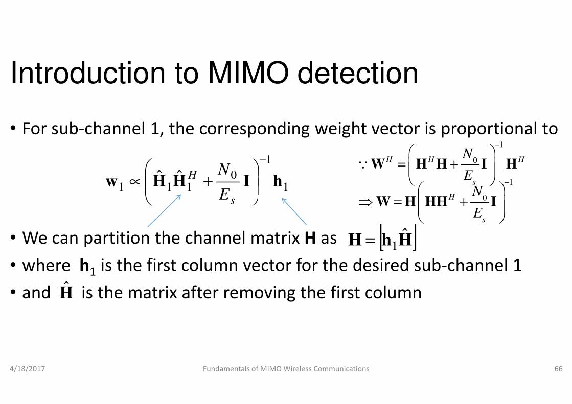
• For sub-channel 1, the corresponding weight vector is proportional to
1
1
0111
ˆˆ hIHHw
−
+∝
s
H
E
N
• We can partition the channel matrix
• where h1 is the first column vector for the desired sub
• and is the matrix after removing the first column
4/18/2017 Fundamentals of MIMO Wireless Communications
sE
H
Introduction to MIMO detection
channel 1, the corresponding weight vector is proportional to
1
1
0
1
0
H H H
s
H
N
EN
−
−
= +
⇒ = +
W H H I H
W H HH I
Q
We can partition the channel matrix H as
is the first column vector for the desired sub-channel 1
and is the matrix after removing the first column
Fundamentals of MIMO Wireless Communications 66
[ ]HhH ˆ1=
0
sE
⇒ = +
W H HH I
Introduction to MIMO detection
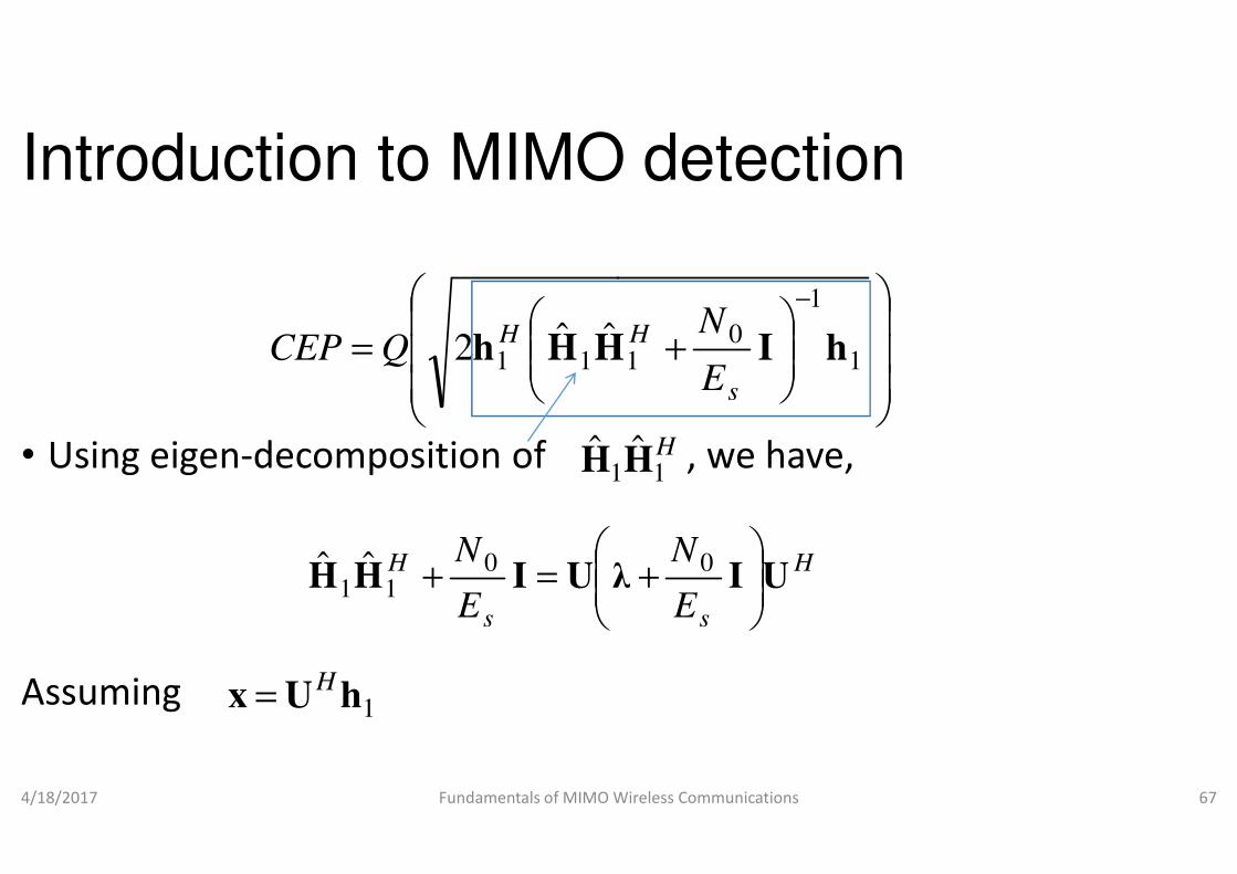
• Using eigen-decomposition of
= 11
ˆˆ2 HHhH
QCEP
H• Using eigen-decomposition of
Assuming
4/18/2017 Fundamentals of MIMO Wireless Communications
1H
s
H
E
NλUIHH
=+ 0
11ˆˆ
1hUxH=
Introduction to MIMO detection
decomposition of , we have,
+
−
1
1
01 hIH
s
H
E
N
HHdecomposition of , we have,
Fundamentals of MIMO Wireless Communications 67
H11H
H
sE
NUIλ
+ 0

Introduction to MIMO detection
• Note that the rank of is
1
01
1
0111
ˆˆN
i s
i
s
HH
E
N
E
N R
=
−
∑
+=
+ λhIHHh
H N −1• Note that the rank of is
• hence, eigenvalues of are zero
4/18/2017 Fundamentals of MIMO Wireless Communications
1H TN −1
1+− TR NN
∑−
=
−
=
+
TR NN
i
s
s
HH
N
E
E
N
101
1
0111
ˆˆ hIHHh
Introduction to MIMO detection
2
1
0i
s
x
−
N≤1
1hUx H=
HH
E
N
E
NUIλUIHH
+=+ 00
11ˆˆ
of are zero
Fundamentals of MIMO Wireless Communications 68
RN≤1
H11
ˆˆ HH
∑∑+−=
−+
++
R
TR
T N
NNi
i
s
ii xE
Nx
2
21
0
12
λ
ss EE
11
Introduction to MIMO detection
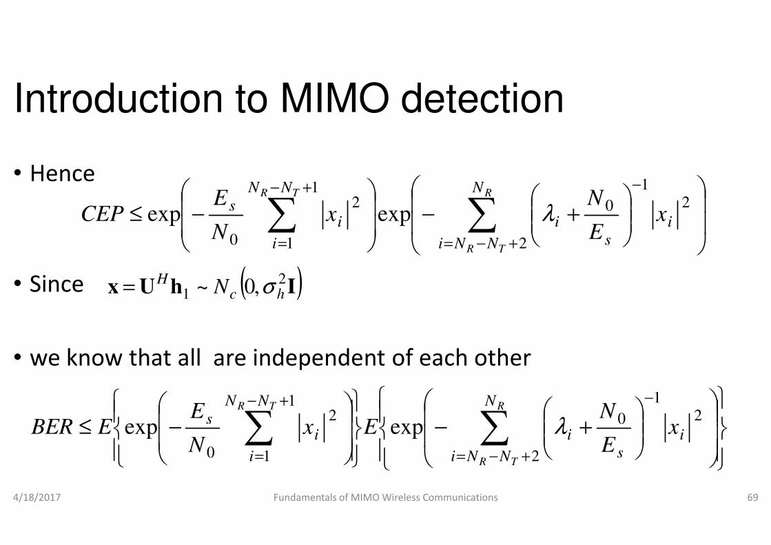
• Hence
• Since
−≤ ∑
+−
=
TR NN
i
is
xN
ECEP
1
1
2
0
expexp
( )2H σ=• Since
• we know that all are independent of each other
4/18/2017 Fundamentals of MIMO Wireless Communications
( )IhUx2
1 ,0~ hcH
N σ=
−≤ ∑
+−
=
TR NN
i
is Ex
N
EEBER
1
1
2
0
exp
Introduction to MIMO detection
+− ∑
+−=
−R
TR
N
NNi
i
s
i xE
N
2
21
0exp λ
we know that all are independent of each other
Fundamentals of MIMO Wireless Communications 69
+− ∑
+−=
−R
TR
N
NNi
i
s
i xE
N
2
21
0exp λ

Introduction to MIMO detection
• which can be approximated as
11
1N
BER
RNN TRγ
+
≅
+−
4/18/2017 Fundamentals of MIMO Wireless Communications
11
1
N
BER
R
γ
γ
++
+≅
+ J. Choi, Optimal Combining & Detection, Cambridge University Press,
Introduction to MIMO detection
2
1
;
1
E hb
NT
σγ
γ=
−
Fundamentals of MIMO Wireless Communications 70
0
;1 N
E hbσγ
γ
γ=
, Cambridge University Press, 2010.

Introduction to MIMO detection
• The diversity gain for ML detection was N
• whereas ZF and MMSE detectors have diversity gain of
• MMSE has slightly higher diversity than ZF
• we will discuss this in conservation theorem• we will discuss this in conservation theorem
• Sphere Decoding
• the complexity of ML detection grows exponentially
• Is there way to reduce this complexity without compromising the performance?
• That’s what sphere decoding (SD) exactly does
4/18/2017 Fundamentals of MIMO Wireless Communications
Introduction to MIMO detection
The diversity gain for ML detection was NR
whereas ZF and MMSE detectors have diversity gain of
MMSE has slightly higher diversity than ZF
we will discuss this in conservation theorem
1R T
N N− +
we will discuss this in conservation theorem
the complexity of ML detection grows exponentially
Is there way to reduce this complexity without compromising the
That’s what sphere decoding (SD) exactly does
Fundamentals of MIMO Wireless Communications 71

Introduction to MIMO detection
• How does SD achieve this?
• It tries to find the ML solution vector within a sphere
• instead of all possible transmitted signal vectors (ML detection)
• But there may be • But there may be
• no vector at all or
• numerous vectors
• inside the chosen sphere
• How to handle such situations?
4/18/2017 Fundamentals of MIMO Wireless Communications
Introduction to MIMO detection
It tries to find the ML solution vector within a sphere
instead of all possible transmitted signal vectors (ML detection)
Fundamentals of MIMO Wireless Communications 72

Introduction to MIMO detection
• In the first case,
• one may increase the radius of the sphere
• In the second case,
• one may decrease the radius of the sphere • one may decrease the radius of the sphere
• so that only one vector exists inside the sphere
• which will give us the ML solution
• Hence, SD is an iterative decoding
• which converges to the ML solution
• when the number of iterations is unbounded
4/18/2017 Fundamentals of MIMO Wireless Communications
Introduction to MIMO detection
one may increase the radius of the sphere
one may decrease the radius of the sphere one may decrease the radius of the sphere
so that only one vector exists inside the sphere
which will give us the ML solution
Hence, SD is an iterative decoding
which converges to the ML solution
when the number of iterations is unbounded
Fundamentals of MIMO Wireless Communications 73

Introduction to MIMO detection
• First step:
• converting the complex I-O MIMO system model
• into an equivalent real system model
4/18/2017 Fundamentals of MIMO Wireless Communications
real real real real
equi equi equi equi⇒ = +y H x n
( )( )
( ) ( )( ) ( )
Re Re Im Re Re
Im Im Re Im Im
− ⇒ = +
y H H x n
y H H x n
Introduction to MIMO detection
O MIMO system model
into an equivalent real system model
= +y Hx n
Fundamentals of MIMO Wireless Communications 74
( )( )
( )( )
Re Re Im Re Re
Im Im Re Im Im
= +
y H H x n
y H H x n

Introduction to MIMO detection
• Example
• Convert a complex MIMO I-O model to an equivalent real system model
• Solution:• Solution:
• For a MIMO system,
4/18/2017 Fundamentals of MIMO Wireless Communications
1 11 12 1 1
2 21 22 2 2
y h h x n
y h h x n
= +
Introduction to MIMO detection
O model to an equivalent real system
Fundamentals of MIMO Wireless Communications 75
1 11 12 1 1
2 21 22 2 2
y h h x n
y h h x n
= +

Introduction to MIMO detection
• Separating the imaginary and real parts, we have,
1 1 11 11 12 12 1 1 1 1
2 2 21 21 22 22 2 2 2 2
real imag real imag real imag real imag real imag
real imag real imag real imag real imag real imag
y jy h jh h jh x jx n jn
y jy h jh h jh x jx n jn
+ + + + +
+ + + + + ⇒ = +
• Hence the real equivalent model is
4/18/2017 Fundamentals of MIMO Wireless Communications
2 2 21 21 22 22 2 2 2 2y jy h jh h jh x jx n jn+ + + + + ⇒ = +
Introduction to MIMO detection
Separating the imaginary and real parts, we have,
1 1 11 11 12 12 1 1 1 1
2 2 21 21 22 22 2 2 2 2
real imag real imag real imag real imag real imag
real imag real imag real imag real imag real imag
y jy h jh h jh x jx n jn
y jy h jh h jh x jx n jn
+ + + + +
+ + + + + = +
Hence the real equivalent model is
Fundamentals of MIMO Wireless Communications 76
2 2 21 21 22 22 2 2 2 2y jy h jh h jh x jx n jn+ + + + + = +

Introduction to MIMO detection
1 11 12 11 12 1
2 21 22 21 22 2
1 11 12 11 12 1
real real real imag imag real
real real real imag imag real
imag imag imag real real imag
imag imag imag real real ima
y h h h h x
y h h h h x
y h h h h x
y h h h h x
− −
− −
=
• MLD for the real equivalent system
• can be expressed as
4/18/2017 Fundamentals of MIMO Wireless Communications
2 21 22 21 22 2y h h h h x
Introduction to MIMO detection
1 11 12 11 12 1
2 21 22 21 22 2
1 11 12 11 12 1
real real real imag imag real
real real real imag imag real
imag imag imag real real imag
imag imag imag real real ima
y h h h h x
y h h h h x
y h h h h x
y h h h h x
− −
− −
1
2
1
real
real
imag
g imag
n
n
n
n
+
MLD for the real equivalent system
Fundamentals of MIMO Wireless Communications 77
2 21 22 21 22 2y h h h h x
2n
2
arg min real real real
equi equi equi
real real
equi equi
−
∈
y H x
x χ
Introduction to MIMO detection
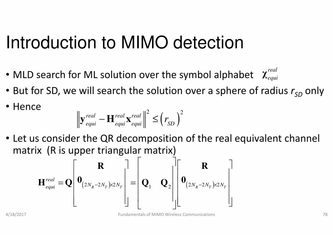
• MLD search for ML solution over the symbol alphabet
• But for SD, we will search the solution over a sphere of radius
• Hence
(2
real real realr− ≤y H x
• Let us consider the QR decomposition of the real equivalent channel matrix (R is upper triangular matrix)
4/18/2017 Fundamentals of MIMO Wireless Communications
(real real real
equi equi equi SDr− ≤y H x
( )2 2 2 2 2 21 2R T T R T T
realN N N N N Nequi − × − ×
= =
R R
0 0H Q Q Q
Introduction to MIMO detection
MLD search for ML solution over the symbol alphabet
But for SD, we will search the solution over a sphere of radius rSD only
real
equiχ
)2
r
Let us consider the QR decomposition of the real equivalent channel matrix (R is upper triangular matrix)
Fundamentals of MIMO Wireless Communications 78
)equi equi equi SDr
( )2 2 2 2 2 21 2R T T R T TN N N N N N− × − ×
R R
0 0H Q Q Q

Introduction to MIMO detection
• Note that is a matrix
• Multiplying by and
real
equiH 2 2
R TN N×
1
H
H
Q
• Multiplying by and
• using the unitary property of the Q
4/18/2017 Fundamentals of MIMO Wireless Communications
2
HH =
Introduction to MIMO detection
Note that is a matrix
Q matrix, we have,
Fundamentals of MIMO Wireless Communications 79

Introduction to MIMO detection
• Therefore,
(
1
2 2 22R T T
H
H real realN N Nequi equi SD− ×
− ≤
Q R
0Q y x
4/18/2017 Fundamentals of MIMO Wireless Communications
2 2
1 2
H real real H real
equi equi SD equi⇒ − ≤ −Q y Rx Q y
+ F. A. Monteiro, I. J. Wassell and N. Souto, “MIMO Detection Methods,” in
4G and beyond, M. M. da Silva and F. A. Monteiro
Introduction to MIMO detection
) ( )
2
2
2 2 2R T T
real realN N Nequi equi SD
r− ×
− ≤
Q R
y x
Fundamentals of MIMO Wireless Communications 80
( )2 22
1 2
H real real H real
equi equi SD equir− ≤ −Q y Rx Q y
, “MIMO Detection Methods,” in MIMO Processing for
Monteiro, Eds., Boca Raton: CRC Press, 2014, pp. 47-117.

Introduction to MIMO detection
• Substituting the new
1
n H real
equi=y Q y ( )
22
2
H real
n SD equir r= − Q y
• Hence,
• Since R is upper triangular matrix,
• we can write the above inequality in component form as
4/18/2017 Fundamentals of MIMO Wireless Communications
( )2 2
n r
nr− ≤y Rx
Introduction to MIMO detection
2r real
equi=x x
is upper triangular matrix,
we can write the above inequality in component form as
Fundamentals of MIMO Wireless Communications 81

Introduction to MIMO detection
• Example
22 2
1 1
T TN N
n r
i ij j ni j
y R x r= =
− ≤
∑ ∑
• Example
• Find the above SD metric for a 2×2
• Solution
4/18/2017 Fundamentals of MIMO Wireless Communications
Introduction to MIMO detection
( ) 2
i ij j ny R x r− ≤
2 MIMO system
Fundamentals of MIMO Wireless Communications 82

Introduction to MIMO detection
• SD metric for a 2×2 MIMO system
1 111 12 13 14
2 22 23 24 20
0 0
n r
n r
n r
y xR R R R
y R R R x
R R
4/18/2017 Fundamentals of MIMO Wireless Communications
33 343 3
4 4
0 0
0 0 0
n r
n r
R Ry x
y x
− ≤
1 11 1 12 2 13 3 14 4 2 22 2 23 3 24 4
2 2
3 33 3 34 4 4 44 4
n r r r r n r r r
n r r n r
y R x R x R x R x y R x R x R x
y R x R x y R x r
⇒ − − − − + − − −
+ − − + − ≤
Introduction to MIMO detection
( )
2
1 111 12 13 14
2 22 23 24 2
n r
n r
n r
y xR R R R
y R R R x
R R
Fundamentals of MIMO Wireless Communications 83
( ) 233 343 3
444 40 0 0
n r
nn r
R Ry x r
Ry x
− ≤
( )
2 2
1 11 1 12 2 13 3 14 4 2 22 2 23 3 24 4
2 2 2
3 33 3 34 4 4 44 4
n r r r r n r r r
n r r n r
n
y R x R x R x R x y R x R x R x
y R x R x y R x r
− − − − + − − −
+ − − + − ≤

Introduction to MIMO detection
• Reordering the terms in the LHS, we have,
2 2 2
4 44 4 3 34 4 33 3 2 24 4 23 3 22 2
n r n r r n r r r
n r r r r
y R x y R x R x y R x R x R x
y R x R x R x R x r
− + − − + − − −
+ − − − − ≤
• Similarly, expanding SD metric for a MIMO system, we have,
4/18/2017 Fundamentals of MIMO Wireless Communications
1 14 4 13 3 12 2 11 1y R x R x R x R x r+ − − − − ≤
2 2
2 2 2 2 2 1 2 1 2 2 2 1 2 1 2 1
1 1 2 2 1 2 1 2 1 11 1
, , ,
, , ,
T T T T T T T T T T T
T T T T
n r n r r
N N N N N N N N N N N
n r r r
N N N N n
y R x y R x R x
y R x R x R x r
− − − − −
− −
− + − −
+ + − − − − ≤L L
Introduction to MIMO detection
Reordering the terms in the LHS, we have,
( )
2 2 2
4 44 4 3 34 4 33 3 2 24 4 23 3 22 2
2 2
n r n r r n r r r
n r r r r
y R x y R x R x y R x R x R x
y R x R x R x R x r
− + − − + − − −
+ − − − − ≤
Similarly, expanding SD metric for a MIMO system, we have,
Fundamentals of MIMO Wireless Communications 84
( )1 14 4 13 3 12 2 11 1 ny R x R x R x R x r+ − − − − ≤
( )
2 2
2 2 2 2 2 1 2 1 2 2 2 1 2 1 2 1
2 2
1 1 2 2 1 2 1 2 1 11 1
, , ,
, , ,
T T T T T T T T T T T
n r n r r
N N N N N N N N N N N
n r r r
N N N N n
y R x y R x R x
y R x R x R x r
− − − − −
− −
− + − −
+ + − − − − ≤L L
Introduction to MIMO detection
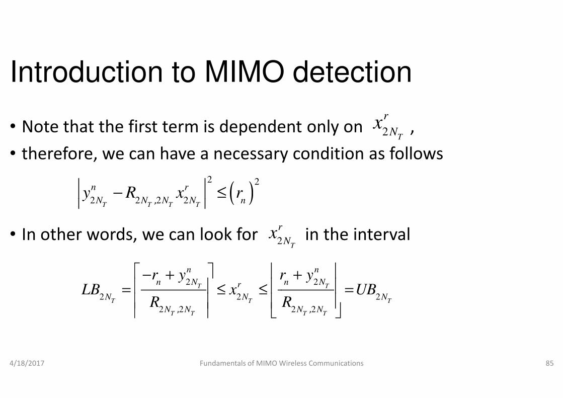
• Note that the first term is dependent only on ,
• therefore, we can have a necessary condition as follows
( )2 2
2 2 2 2,
n r
N N N N ny R x r− ≤
• In other words, we can look for in the interval
4/18/2017 Fundamentals of MIMO Wireless Communications
( )2 2 2 2,T T T T
N N N N ny R x r− ≤
2
rx
2 2
2 2 2
2 2 2 2, ,
T T
T T T
T T T T
n n
n N n Nr
N N N
N N N N
r y r yLB x UB
R R
− + + = ≤ ≤ =
Introduction to MIMO detection
Note that the first term is dependent only on ,
therefore, we can have a necessary condition as follows
2T
r
Nx
In other words, we can look for in the interval
Fundamentals of MIMO Wireless Communications 85
2T
r
Nx
2 2
2 2 2
2 2 2 2, ,
T T
T T T
T T T T
n n
n N n N
N N N
N N N N
r y r yLB x UB
R R
− + + = ≤ ≤ =
Introduction to MIMO detection
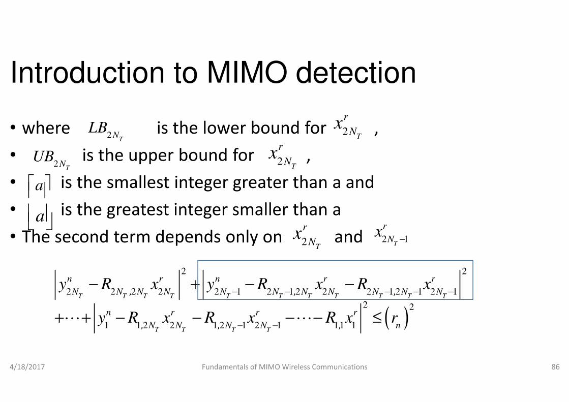
• where is the lower bound for ,
• is the upper bound for ,
• is the smallest integer greater than a and
• is the greatest integer smaller than a
2T
NLB
2T
NUB 2
r
Nx
a • is the greatest integer smaller than a
• The second term depends only on and
4/18/2017 Fundamentals of MIMO Wireless Communications
a
2 2
2 2 2 2 2 1 2 1 2 2 2 1 2 1 2 1
1 1 2 2 1 2 1 2 1 11 1
, , ,
, , ,
T T T T T T T T T T T
T T T T
n r n r r
N N N N N N N N N N N
n r r r
N N N N n
y R x y R x R x
y R x R x R x r
− − − − −
− −
− + − −
+ + − − − − ≤L L
Introduction to MIMO detection
where is the lower bound for ,
is the upper bound for ,
is the smallest integer greater than a and
is the greatest integer smaller than a
2T
r
Nx
2T
r
Nx
is the greatest integer smaller than a
The second term depends only on and
Fundamentals of MIMO Wireless Communications 86
2T
r
Nx 2 1
T
r
Nx
−
( )
2 2
2 2 2 2 2 1 2 1 2 2 2 1 2 1 2 1
2 2
1 1 2 2 1 2 1 2 1 11 1
, , ,
, , ,
T T T T T T T T T T T
n r n r r
N N N N N N N N N N N
n r r r
N N N N n
y R x y R x R x
y R x R x R x r
− − − − −− + − −
+ + − − − − ≤L L
Introduction to MIMO detection
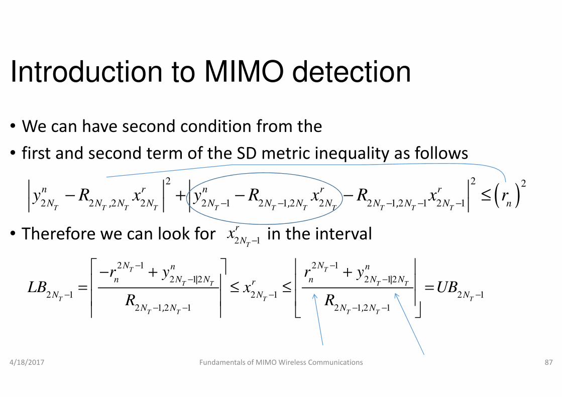
• We can have second condition from the
• first and second term of the SD metric inequality as follows
2 2
2 2 2 2 2 1 2 1 2 2 2 1 2 1 2 1, , ,
n r n r r
N N N N N N N N N N N ny R x y R x R x r
− − − − −− + − − ≤
• Therefore we can look for in the interval
4/18/2017 Fundamentals of MIMO Wireless Communications
2 2 2 2 2 1 2 1 2 2 2 1 2 1 2 1, , ,T T T T T T T T T T T
N N N N N N N N N N N ny R x y R x R x r
− − − − −− + − − ≤
2 1T
r
Nx
−
2 1 2 1
2 12 2 12
2 1 2 1 2 1
2 1 2 1 2 1 2 1
| |
, ,
T T
T T T T
T T T
T T T T
N Nn n
n N N n N Nr
N N N
N N N N
r y r yLB x UB
R R
− −
− −
− − −
− − − −
− + + = ≤ ≤ =
Introduction to MIMO detection
We can have second condition from the
first and second term of the SD metric inequality as follows
( )2 2 2
2 2 2 2 2 1 2 1 2 2 2 1 2 1 2 1, , ,
n r n r r
N N N N N N N N N N N ny R x y R x R x r
− − − − −− + − − ≤
Therefore we can look for in the interval
Fundamentals of MIMO Wireless Communications 87
( )2 2 2 2 2 1 2 1 2 2 2 1 2 1 2 1, , ,T T T T T T T T T T T
N N N N N N N N N N N ny R x y R x R x r
− − − − −− + − − ≤
2 1 2 1
2 12 2 12
2 1 2 1 2 1
2 1 2 1 2 1 2 1
| |
, ,
T T
T T T T
T T T
T T T T
N Nn n
n N N n N N
N N N
N N N N
r y r yLB x UB
R R
− −
− −
− − −
− − − −
− + + = ≤ ≤ =

Introduction to MIMO detection
• Where2 12 2 1 2 1 2 2| ,
T T T T T T
n n r
N N N N N Ny y R x
− − −= −
( ) ( )2 22 1
2 2 2 2,T
T T T T
N n r
n n N N N Nr r y R x
−= − −
• Following the same procedure,
• we can find the interval in which one can look for
4/18/2017 Fundamentals of MIMO Wireless Communications
( ) ( ) 2 2 2 2,T T T T
n n N N N N
2 2 2 3 1, , ,
T T
r r r
N Nx x x
− −L
Introduction to MIMO detection
2 12 2 1 2 1 2 2| ,T T T T T T
n n r
N N N N N Ny y R x
2
2 2 2 2,T T T T
n r
n n N N N Nr r y R x
we can find the interval in which one can look for
Fundamentals of MIMO Wireless Communications 88
2 2 2 2,T T T T
n n N N N N
Introduction to MIMO detection
• In SD, the multidimensional search of MLD is transformed
• to multiple searches in one dimension
• Example
• Write the SD pseudo code for a simple 2• Write the SD pseudo code for a simple 2
• Solution:
• Step 1:
• Find the QR factorization of
4/18/2017 Fundamentals of MIMO Wireless Communications
Introduction to MIMO detection
In SD, the multidimensional search of MLD is transformed
to multiple searches in one dimension
Write the SD pseudo code for a simple 2×2 MIMO system.Write the SD pseudo code for a simple 2×2 MIMO system.
Fundamentals of MIMO Wireless Communications 89
Introduction to MIMO detection
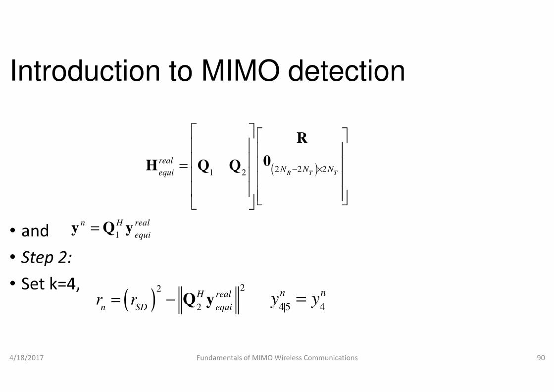
(2 2 21 2
real
equi
=
0H Q Q
• and
• Step 2:
• Set k=4,
4/18/2017 Fundamentals of MIMO Wireless Communications
1
n H real
equi=y Q y
( )22
2
H real
n SD equir r= − Q y y y
Introduction to MIMO detection
)2 2 2R T T
N N N− ×
R
0
Fundamentals of MIMO Wireless Communications 90
45 4|
n ny y=

Introduction to MIMO detection
• Step 3:
• Set the bounds
1 1| |
, ,
k n k n
n k k n k krr y r y
LB x UB+ +
− + + = ≤ ≤ =
• Step 4:
• Increase
4/18/2017 Fundamentals of MIMO Wireless Communications
| |
, ,
k k k
k k k k
LB x UBR R
= ≤ ≤ =
1r
k kx LB= −
1k k
x x= +
Introduction to MIMO detection
1 1| |
, ,
k n k n
n k k n k kr y r y
LB x UB+ +
− + + = ≤ ≤ =
Fundamentals of MIMO Wireless Communications 91
| |
, ,
k k k
k k k k
LB x UBR R
= ≤ ≤ =

Introduction to MIMO detection
• Decision 1: ?
• If no then
• Step 6:
• k=k+1
r
k kx UB≤
• k=k+1
• Decision 2: k=5?
• If yes then
• stop.
• If no then go to step 4
4/18/2017 Fundamentals of MIMO Wireless Communications
Introduction to MIMO detection
Fundamentals of MIMO Wireless Communications 92

Introduction to MIMO detection
• If yes then
• Decision 3: k=1?
• If no then
• Step 5: Decrease k=k-1• Step 5: Decrease k=k-1
4/18/2017 Fundamentals of MIMO Wireless Communications
2
11
| ,
TN
n n r
k k k k j jj k
y y R x+
= +
= − ∑ ( ) (2 2 2
k k n r
n n k k k k kr r y R x
+= − −
Introduction to MIMO detection
Fundamentals of MIMO Wireless Communications 93
) ( )2 2 2
1
1 2 1 1 1| ,
k k n r
n n k k k k kr r y R x
+
+ + + + += − −
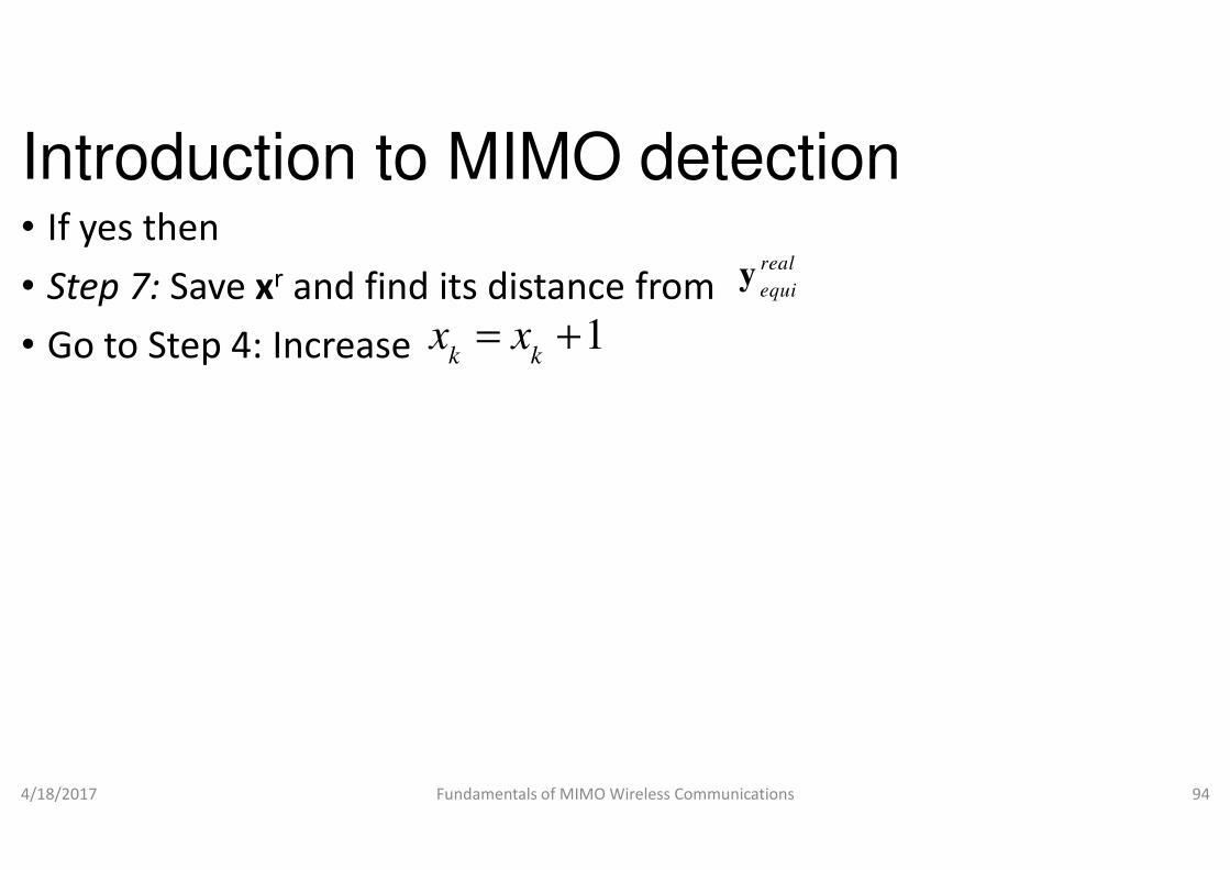
Introduction to MIMO detection• If yes then
• Step 7: Save xr and find its distance from
• Go to Step 4: Increase 1k k
x x= +
4/18/2017 Fundamentals of MIMO Wireless Communications
Introduction to MIMO detection
and find its distance from real
equiy
Fundamentals of MIMO Wireless Communications 94
Introduction to MIMO detection
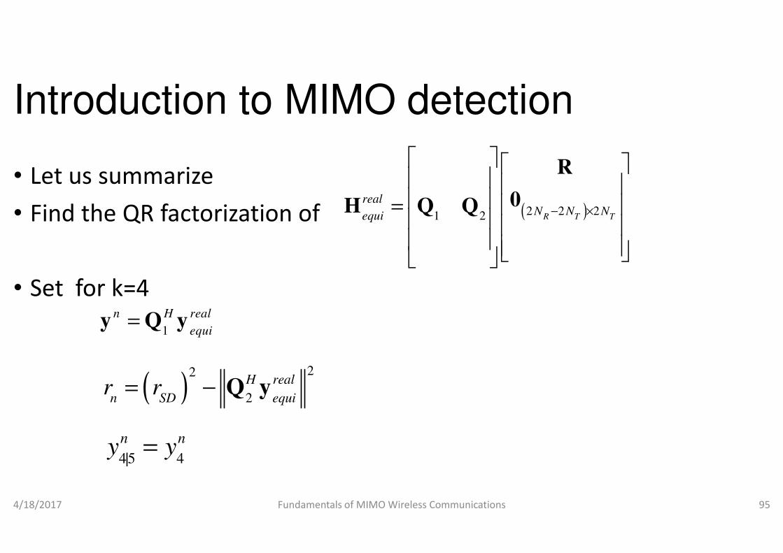
• Let us summarize
• Find the QR factorization of
• Set for k=4
real
equi=H Q Q
• Set for k=4
4/18/2017 Fundamentals of MIMO Wireless Communications
1
n H real
equi=y Q y
( )22
2
H real
n SD equir r= − Q y
45 4|
n ny y=
Introduction to MIMO detection
( )2 2 21 2 R T T
realN N Nequi − ×
=
R
0H Q Q
Fundamentals of MIMO Wireless Communications 95

Introduction to MIMO detection
• Choose a candidate point from the following range
• If there exists not candidate point in the range,
1 1| |
, ,
k n k n
n k k n k kr
k k k
k k k k
r y r yLB x UB
R R
+ + − + + = ≤ ≤ =
rx 4
• If there exists not candidate point in the range,
• the radius needs to be increased
• If the a candidate point has been chosen successfully,
• then we proceed to find a candidate point in the range for k=3
4/18/2017 Fundamentals of MIMO Wireless Communications
+ Y. S. Cho, J. Kim, W. Y. Yang and C.-G. Kang, MIMO
MATLAB, Wiley, 2010.
Introduction to MIMO detection
Choose a candidate point from the following range
If there exists not candidate point in the range,
1 1| |
, ,
k n k n
n k k n k kr
k k k
k k k k
r y r yLB x UB
R R
+ + − + + = ≤ ≤ =
If there exists not candidate point in the range,
If the a candidate point has been chosen successfully,
then we proceed to find a candidate point in the range for k=3
Fundamentals of MIMO Wireless Communications 96
rx 3
MIMO-OFDM wireless communications using
Introduction to MIMO detection
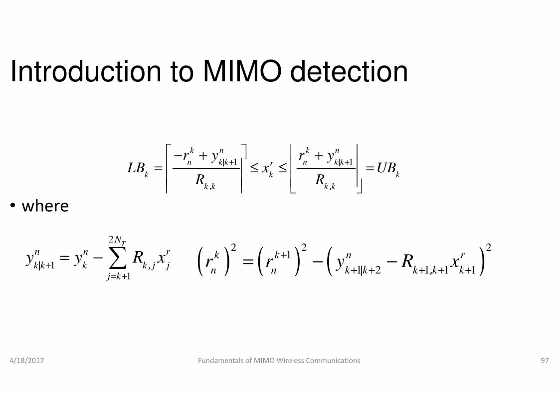
• where
1 1| |
, ,
k n k n
n k k n k kr
k k k
k k k k
r y r yLB x UB
R R
+ + − + + = ≤ ≤ =
• where
4/18/2017 Fundamentals of MIMO Wireless Communications
2
11
| ,
TN
n n r
k k k k j jj k
y y R x+
= +
= − ∑ ( ) (2 2 2
k k n r
n n k k k k kr r y R x= − −
Introduction to MIMO detection
1 1| |
, ,
k n k n
n k k n k kr
k k k
k k k k
r y r yLB x UB
R R
+ + − + + = ≤ ≤ =
Fundamentals of MIMO Wireless Communications 97
) ( )2 2 2
1
1 2 1 1 1| ,
k k n r
n n k k k k kr r y R x
+
+ + + + += − −

Introduction to MIMO detection
• If a candidate value for does not exist,
• then go back to the previous step and choose another value of
• Then search for that meets the bound for that new value of
• In case no candidate exist for for
rx 3
rx 3
rx• In case no candidate exist for for
• Increase the radius of the sphere
• Assume that and are the final chosen candidate points
• Given and , a candidate fointervals
4/18/2017 Fundamentals of MIMO Wireless Communications
rx 3
rx 4
rx 3
rx 4
rx 3
Introduction to MIMO detection
If a candidate value for does not exist,
then go back to the previous step and choose another value of
Then search for that meets the bound for that new value of
for all possible values of
rx 4
rx 4
rxfor all possible values of
Assume that and are the final chosen candidate points
te for is chosen for k=2 from the
Fundamentals of MIMO Wireless Communications 98
rx 4
rx 2

Introduction to MIMO detection
• where
1 1| |
, ,
k n k n
n k k n k kr
k k k
k k k k
r y r yLB x UB
R R
+ + − + + = ≤ ≤ =
• where
4/18/2017 Fundamentals of MIMO Wireless Communications
2
11
| ,
TN
n n r
k k k k j jj k
y y R x+
= +
= − ∑ ( ) (2 2 2
k k n r
n n k k k k kr r y R x= − −
Introduction to MIMO detection
1 1| |
, ,
k n k n
n k k n k kr
k k k
k k k k
r y r yLB x UB
R R
+ + − + + = ≤ ≤ =
Fundamentals of MIMO Wireless Communications 99
) ( )2 2 2
1
1 2 1 1 1| ,
k k n r
n n k k k k kr r y R x
+
+ + + + += − −

Introduction to MIMO detection
• If a candidate value for does not exist,
• then go back to the previous step and choose another value of
• Then search for that meets the bound for that new value of
• In case no candidate exist for for
rx 2
rx 2
rx• In case no candidate exist for for
• Then we go back the step before previous,
• and choose another value of
• Assume that and are the final chosen candidate points
4/18/2017 Fundamentals of MIMO Wireless Communications
rx 2
rx 4
rx 2
rx 3
rx 4
Introduction to MIMO detection
If a candidate value for does not exist,
then go back to the previous step and choose another value of
Then search for that meets the bound for that new value of
for all possible values of
rx 3
rx 3
rxfor all possible values of
Then we go back the step before previous,
Assume that and are the final chosen candidate
Fundamentals of MIMO Wireless Communications 100
rx 3
r
2

Introduction to MIMO detection• Similarly, we can find
• and are the final chosen candidate points
• And it turns out to be a single point
• It is declared as the ML solution vector and search stops
• How do we decide the radius of the sphere?
rx1
rx 4
rx 3
rx 2
rx1
• How do we decide the radius of the sphere?
• We can choose where is the noise variance
• Hence for low SNR the radius of the sphere is large and SD is less efficient
• SD is highly efficient for high SNR since the sphere radius is small
4/18/2017 Fundamentals of MIMO Wireless Communications
( ) 22nRSD Nr σ∝
+ T. Kailath, H. Vikalo and B. Hassibi, “MIMO Receive
From Array Processing to MIMO Communications,
van der Veen, Eds., Cambridge, UK: Cambridge University Press, 2006, pp. 302
Introduction to MIMO detection
and are the final chosen candidate points
oint within the sphere with that radius
It is declared as the ML solution vector and search stops
How do we decide the radius of the sphere? How do we decide the radius of the sphere?
We can choose where is the noise variance
Hence for low SNR the radius of the sphere is large and SD is less
SD is highly efficient for high SNR since the sphere radius is small
Fundamentals of MIMO Wireless Communications 101
2nσ
, “MIMO Receive Algorithms,”in Space-Time Wireless Systems:
From Array Processing to MIMO Communications, H. Bolcskei, D. Gesbert, C. Papadias, and A. J.
, Eds., Cambridge, UK: Cambridge University Press, 2006, pp. 302-321

Advanced MIMO detection techniques
Fig. Vertical Layered Space Time Transmission
4/18/2017 Fundamentals of MIMO Wireless Communications
Advanced MIMO detection techniques
Fig. Vertical Layered Space Time Transmission
Fundamentals of MIMO Wireless Communications 102
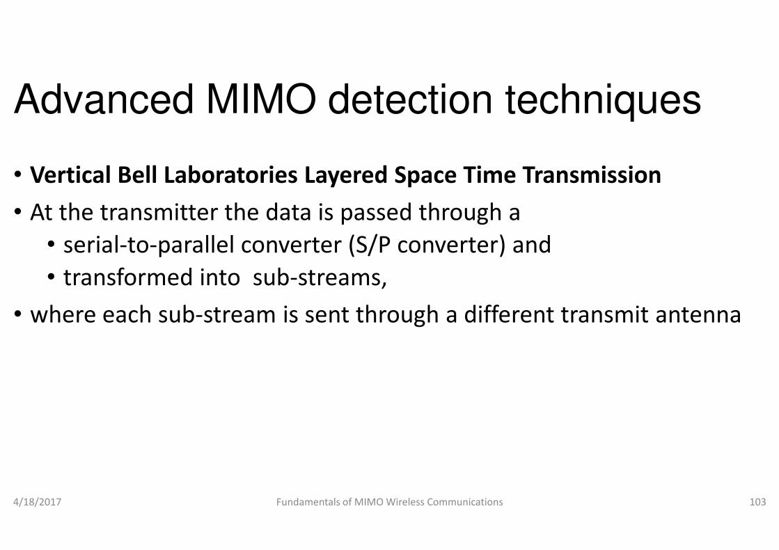
Advanced MIMO detection techniques
• Vertical Bell Laboratories Layered Space Time Transmission
• At the transmitter the data is passed through a
• serial-to-parallel converter (S/P converter) and
• transformed into sub-streams, • transformed into sub-streams,
• where each sub-stream is sent through a different transmit antenna
4/18/2017 Fundamentals of MIMO Wireless Communications
Advanced MIMO detection techniques
Vertical Bell Laboratories Layered Space Time Transmission
At the transmitter the data is passed through a
parallel converter (S/P converter) and
streams, streams,
stream is sent through a different transmit antenna
Fundamentals of MIMO Wireless Communications 103

Advanced MIMO detection techniques
• As usual in any communication system,
• after the S/P converter,
• all sub-streams will be modulated and
• may be interleaved and • may be interleaved and
• sent through the transmitting antenna
4/18/2017 Fundamentals of MIMO Wireless Communications
Advanced MIMO detection techniques
As usual in any communication system,
streams will be modulated and
sent through the transmitting antenna
Fundamentals of MIMO Wireless Communications 104

Advanced MIMO detection techniques
• The transmission matrix (X) for V-BLAST can be represented as
11 2 1 3 1
1 2 2 2 3 2
, , ,
, , ,
x x x
x x x
• where in , t is the time index and j is the antenna index
4/18/2017 Fundamentals of MIMO Wireless Communications
1 2 2 2 3 2
1 2 3
, , ,
, , ,
, , ,T T T
N N Nx x x
=
X M M M M
,t jx
Advanced MIMO detection techniques
BLAST can be represented as
11 2 1 3 1
1 2 2 2 3 2
, , ,
, , ,
x x x
x x x
L
L
, t is the time index and j is the antenna index
Fundamentals of MIMO Wireless Communications 105
1 2 2 2 3 2
1 2 3
, , ,
, , ,
, , ,T T T
N N Nx x x
M M M M
L

Advanced MIMO detection techniques
• First row of matrix is transmitted from the first antenna for time t=1,2,3,…
• Second row of matrix is transmitted from the second antenna for time t=1,2,3,… time t=1,2,3,…
• and so on
• Example
• For NT=5, write down the transmission matrix for Vtransmission.
• Assume that there are 35 sub-streams.
4/18/2017 Fundamentals of MIMO Wireless Communications
Advanced MIMO detection techniques
matrix is transmitted from the first antenna for time
matrix is transmitted from the second antenna for
=5, write down the transmission matrix for V-BLAST
streams.
Fundamentals of MIMO Wireless Communications 106

Advanced MIMO detection techniques
• The V-BLAST demultiplex the data stream into subto as layers
• and sent one sub-stream over one transmit antenna
161161
4/18/2017 Fundamentals of MIMO Wireless Communications
=
2015105
191494
181383
171272
161161
X
Advanced MIMO detection techniques
the data stream into sub-streams referred
stream over one transmit antenna
312621
Fundamentals of MIMO Wireless Communications 107
353025
342924
332823
322722
312621
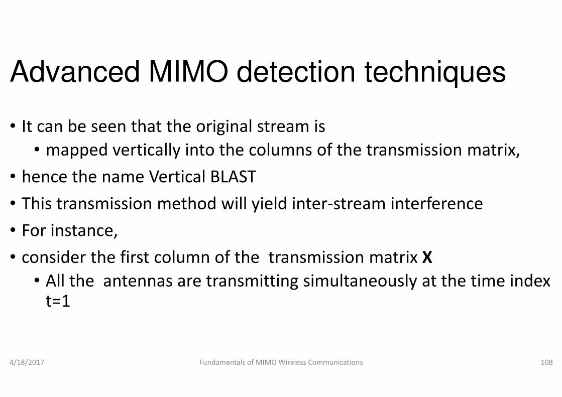
Advanced MIMO detection techniques
• It can be seen that the original stream is
• mapped vertically into the columns of the transmission matrix,
• hence the name Vertical BLAST
• This transmission method will yield inter• This transmission method will yield inter
• For instance,
• consider the first column of the transmission matrix
• All the antennas are transmittingt=1
4/18/2017 Fundamentals of MIMO Wireless Communications
Advanced MIMO detection techniques
It can be seen that the original stream is
mapped vertically into the columns of the transmission matrix,
This transmission method will yield inter-stream interferenceThis transmission method will yield inter-stream interference
consider the first column of the transmission matrix X
itting simultaneously at the time index
Fundamentals of MIMO Wireless Communications 108

Advanced MIMO detection techniques
• Hence any antenna at the receiver will receive
• all the signals streams from transmitting antennas 1 to N
• V-BLAST detection is done with
• zero forcing successive interference cancellation (ZF• zero forcing successive interference cancellation (ZF
• minimum mean square error successive interference cancellation (MMSE-SIC)
• which will cancel the interference from the previously detected signals
4/18/2017 Fundamentals of MIMO Wireless Communications
Advanced MIMO detection techniques
Hence any antenna at the receiver will receive
all the signals streams from transmitting antennas 1 to NT
zero forcing successive interference cancellation (ZF-SIC)zero forcing successive interference cancellation (ZF-SIC)
minimum mean square error successive interference cancellation
which will cancel the interference from the previously detected
Fundamentals of MIMO Wireless Communications 109

Advanced MIMO detection techniques
Fig. Horizontal Layered Space Time Transmission4/18/2017 Fundamentals of MIMO Wireless Communications
Advanced MIMO detection techniques
Fig. Horizontal Layered Space Time TransmissionFundamentals of MIMO Wireless Communications 110

Advanced MIMO detection techniques• If we introduce channel coding for each data sub
• before modulation in the V-BLAST
• then we have horizontal BLAST
• V-BLAST architecture can also include
• optional encoder in series after the message source• optional encoder in series after the message source
• But the main difference between
• V-BLAST and H-BLAST
• is that in V-BLAST
4/18/2017 Fundamentals of MIMO Wireless Communications
+ D.-S. Shiu and M. Kahn, “Layered space-time codes for wireless communications using multiple
transmit antennas,” IEEE International Conference on Communications
440
Advanced MIMO detection techniquesIf we introduce channel coding for each data sub-streams
BLAST
BLAST architecture can also include
optional encoder in series after the message sourceoptional encoder in series after the message source
Fundamentals of MIMO Wireless Communications 111
time codes for wireless communications using multiple
IEEE International Conference on Communications, June 1999, vol. 1, pp. 436 -
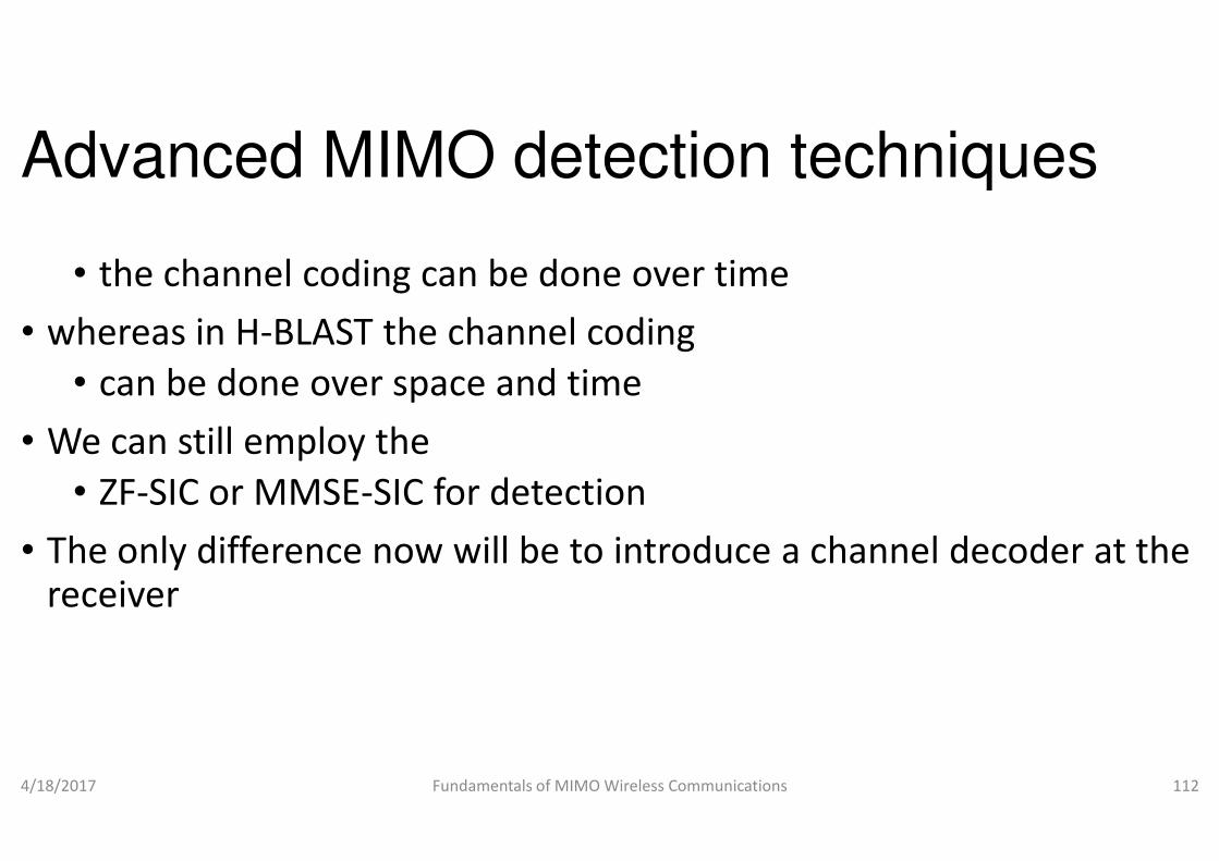
Advanced MIMO detection techniques
• the channel coding can be done over time
• whereas in H-BLAST the channel coding
• can be done over space and time
• We can still employ the • We can still employ the
• ZF-SIC or MMSE-SIC for detection
• The only difference now will be to inreceiver
4/18/2017 Fundamentals of MIMO Wireless Communications
Advanced MIMO detection techniques
the channel coding can be done over time
BLAST the channel coding
can be done over space and time
SIC for detection
to introduce a channel decoder at the
Fundamentals of MIMO Wireless Communications 112

Advanced MIMO detection techniques
• Diagonal Bell Labs Layered Space Time Transmission
• The information stream is DMUX into sub
• and each data sub-stream is transmitted by a different antenna
• through a diagonal interleaving scheme• through a diagonal interleaving scheme
• Table in next slide shows four different data subfor instance
• The sub-streams are cyclically shifted
• before sending it over the NT antennas
4/18/2017 Fundamentals of MIMO Wireless Communications
Advanced MIMO detection techniques
Diagonal Bell Labs Layered Space Time Transmission
The information stream is DMUX into sub-streams
stream is transmitted by a different antenna
through a diagonal interleaving schemethrough a diagonal interleaving scheme
Table in next slide shows four different data sub-streams a, b, c and d
streams are cyclically shifted
antennas
Fundamentals of MIMO Wireless Communications 113
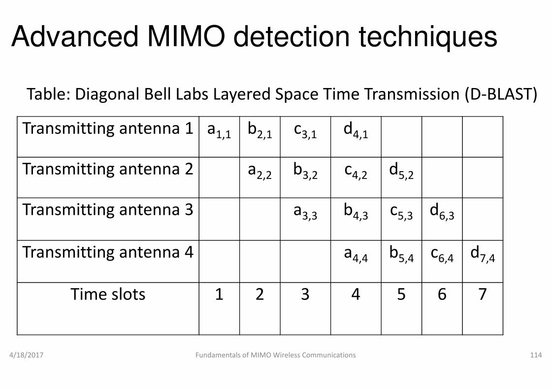
Advanced MIMO detection techniques
Transmitting antenna 1 a1,1 b2,1
Transmitting antenna 2 a2,2
Table: Diagonal Bell Labs Layered Space Time Transmission (D
Transmitting antenna 3
Transmitting antenna 4
Time slots 1 2
4/18/2017 Fundamentals of MIMO Wireless Communications
Advanced MIMO detection techniques
c3,1 d4,1
b3,2 c4,2 d5,2
Table: Diagonal Bell Labs Layered Space Time Transmission (D-BLAST)
a3,3 b4,3 c5,3 d6,3
a4,4 b5,4 c6,4 d7,4
3 4 5 6 7
Fundamentals of MIMO Wireless Communications 114
Advanced MIMO detection techniques
• Note that a1,1, a2,2, a3,3 and a4,4 are referring to the same sub
• which has been transmitted from the 1transmitting antenna
• at time slots 1, 2, 3 and 4 respectively• at time slots 1, 2, 3 and 4 respectively
• It will ensure higher diversity order than the H
• since same sub-streams are transmitted from different antennas
• This results in diagonally layered signal in space and time
4/18/2017 Fundamentals of MIMO Wireless Communications
Advanced MIMO detection techniques
are referring to the same sub-stream
which has been transmitted from the 1st, 2nd, 3rd and 4th
at time slots 1, 2, 3 and 4 respectivelyat time slots 1, 2, 3 and 4 respectively
It will ensure higher diversity order than the H-BLAST
streams are transmitted from different antennas
This results in diagonally layered signal in space and time
Fundamentals of MIMO Wireless Communications 115
Advanced MIMO detection techniques
• As we can see from Table,
• for NT=4, there are four layers and
• each codeword is divided into four blocks
• number of blocks should be equal to N• number of blocks should be equal to N
• The decoder decode layer (sub-stream) by layer
• The first layer is detected without any error
• since it is transmitted alone ( refer to Table)
4/18/2017 Fundamentals of MIMO Wireless Communications
Advanced MIMO detection techniques
=4, there are four layers and
each codeword is divided into four blocks
number of blocks should be equal to NTnumber of blocks should be equal to NT
stream) by layer
The first layer is detected without any error
since it is transmitted alone ( refer to Table)
Fundamentals of MIMO Wireless Communications 116
Advanced MIMO detection techniques
• After that, the second layer is demodulated and detected
• and it has only one interferer from the first layer
• But the first layer is already decoded,
• it can be subtracted• it can be subtracted
• The third will face two interferers
• But the first and second layers are already detected and
• they can be subtracted
4/18/2017 Fundamentals of MIMO Wireless Communications
Advanced MIMO detection techniques
After that, the second layer is demodulated and detected
and it has only one interferer from the first layer
But the first layer is already decoded,
But the first and second layers are already detected and
Fundamentals of MIMO Wireless Communications 117

Advanced MIMO detection techniques
• The process goes on
• Note that the decoding in the previous layers should be error free,
• otherwise the whole process would suffer from error propagation
• ZF-SIC and MMSE-SIC algorithms could be employed• ZF-SIC and MMSE-SIC algorithms could be employed
• There are many unused time slots
• some of the transmitting antennas are sitting idle in D
• threaded D-BLAST can be employed to increase transmission rate
4/18/2017 Fundamentals of MIMO Wireless Communications
+ T. M. Duman & A. Ghrayeb, Coding for MIMO communication systems
Advanced MIMO detection techniques
Note that the decoding in the previous layers should be error free,
otherwise the whole process would suffer from error propagation
SIC algorithms could be employedSIC algorithms could be employed
some of the transmitting antennas are sitting idle in D-BLAST,
BLAST can be employed to increase transmission rate
Fundamentals of MIMO Wireless Communications 118
Coding for MIMO communication systems, John Wiley & Sons, 2007.

Advanced MIMO detection techniques
• Example
• For NT=5, write down the transmission matrix for Dtransmission
3451
4/18/2017 Fundamentals of MIMO Wireless Communications
=
2345
1234
5123
4512
3451
X
Advanced MIMO detection techniques
=5, write down the transmission matrix for D-BLAST
5123
Fundamentals of MIMO Wireless Communications 119
4512
3451
2345
1234
5123
Advanced MIMO detection techniques
• There are as many sub-streams or layers
• as the number of transmit antennas
• But the sub-streams are not transmitted
• as it is unlike V-BLAST• as it is unlike V-BLAST
• The sub-streams are cyclically reordered
• and are transmitted repeatedly
4/18/2017 Fundamentals of MIMO Wireless Communications
Advanced MIMO detection techniques
streams or layers
as the number of transmit antennas
streams are not transmitted
streams are cyclically reordered
and are transmitted repeatedly
Fundamentals of MIMO Wireless Communications 120
Advanced MIMO detection techniques
• Successive interference cancellation
• For V-BLAST detection
• Zero forcing successive interference cancellation (ZF
• Aim is to detect and decode these streams one by one• Aim is to detect and decode these streams one by one
• When the receiver want to decode a stream from one transmitting antenna,
• all other streams from the remaining transmitting antennas are acting as an interferer
• Is there any way of removing these inter
4/18/2017 Fundamentals of MIMO Wireless Communications
Advanced MIMO detection techniques
Successive interference cancellation detection
Zero forcing successive interference cancellation (ZF-SIC)
Aim is to detect and decode these streams one by oneAim is to detect and decode these streams one by one
When the receiver want to decode a stream from one transmitting
all other streams from the remaining transmitting antennas are
Is there any way of removing these inter-stream interferers?
Fundamentals of MIMO Wireless Communications 121

Advanced MIMO detection techniques
• Assume any channel matrix
• which can be decomposed as H=QR
• where Q is a matrix
• with its orthonormal columns being the ZF
R TN N×
R TN N×
• with its orthonormal columns being the ZF
4/18/2017 Fundamentals of MIMO Wireless Communications
=⇒
==
MMMM
L
MMMM
N
HH
qqqQ
IQQQQ
21
Advanced MIMO detection techniques
Assume any channel matrix H where
QR
columns being the ZF nulling vectors
T RN N≤
columns being the ZF nulling vectors
Fundamentals of MIMO Wireless Communications 122
TN
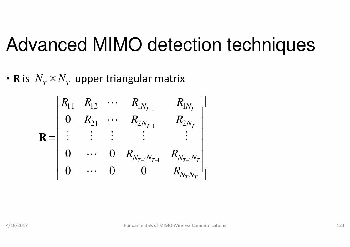
Advanced MIMO detection techniques
• R is upper triangular matrixT T
N N×
−
−
T
T
N
N
RR
RRR
01
1
221
11211
L
L
4/18/2017 Fundamentals of MIMO Wireless Communications
=
−−
−
TT
T
NN
N
R
RR
RR
000
00
0
11
1221
L
L
MMMM
L
R
Advanced MIMO detection techniques
is upper triangular matrix
T
T
N
N
R
R
2
1
Fundamentals of MIMO Wireless Communications 123
−
TT
TT
T
NN
NN
N
R
R
R
1
2
M
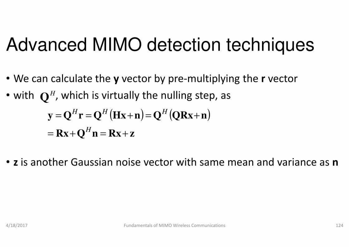
Advanced MIMO detection techniques
• We can calculate the y vector by pre
• with , which is virtually the nullingHQ
( ) (QRxQnHxQrQy =+== HHH
• z is another Gaussian noise vector with same mean and variance as
4/18/2017 Fundamentals of MIMO Wireless Communications
zRxnQRx +=+= H
Advanced MIMO detection techniques
vector by pre-multiplying the r vector
nulling step, as
)nQRx+
is another Gaussian noise vector with same mean and variance as n
Fundamentals of MIMO Wireless Communications 124
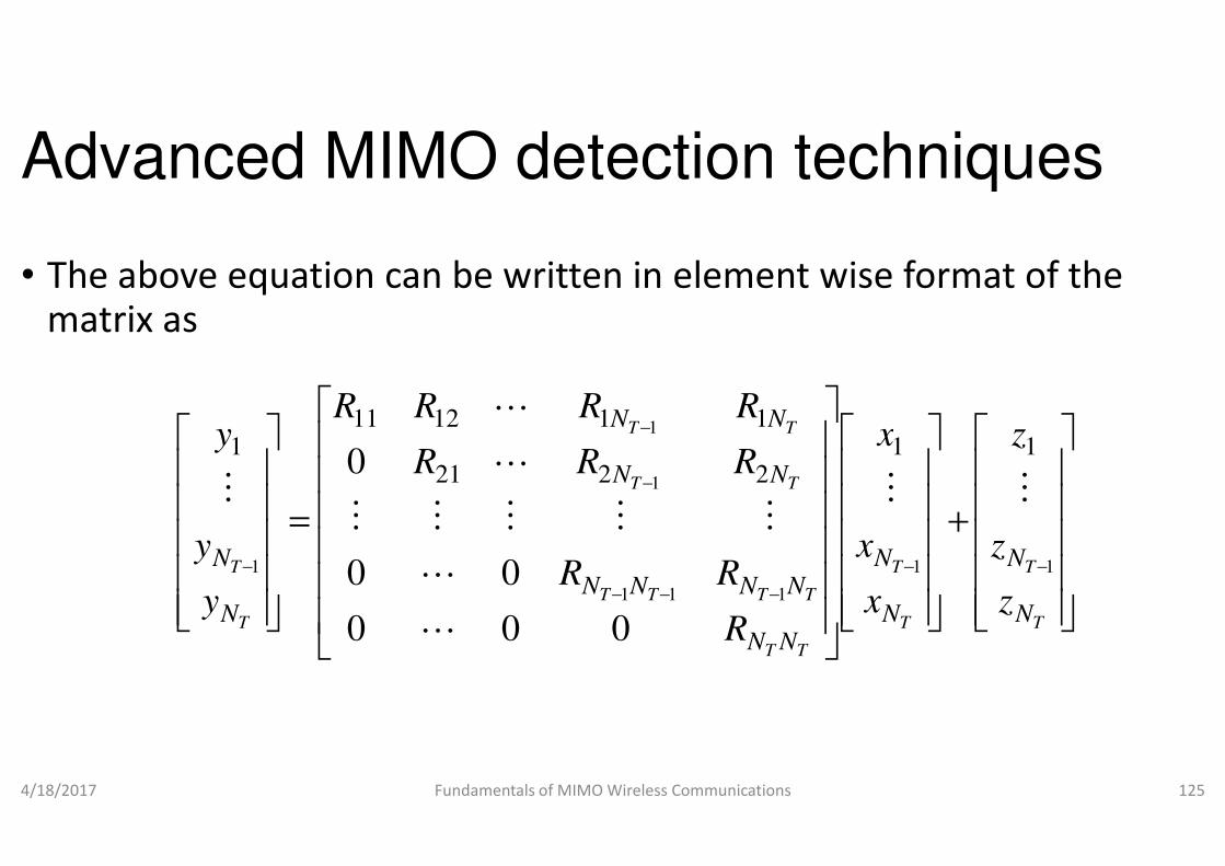
Advanced MIMO detection techniques
• The above equation can be written in element wise format of the matrix as
NRRR
y11211
1
L
4/18/2017 Fundamentals of MIMO Wireless Communications
=
−
−
T
T
T
N
N
N
NR
RR
y
y
y
1
2211
000
00
0
L
L
MMM
LM
Advanced MIMO detection techniques
The above equation can be written in element wise format of the
− TT NNzx
R1
111
Fundamentals of MIMO Wireless Communications 125
+
−−
−−−
−
−
T
T
T
T
TT
TTT
TT
TT
N
N
N
N
NN
NNN
NN
z
z
z
x
x
x
R
R
R
11
111
1
1
112
0
MMMM

Advanced MIMO detection techniques
• which is basically
+
+++
=
xR
RxRxR
y
y 2121111 L
M
• Note that
4/18/2017 Fundamentals of MIMO Wireless Communications
+=
−−−−
TT
TTT
T
T
NN
NNN
N
N
R
xR
y
y1111
i
N
j
jiji izxRyT
,,2,1;
1
L=+=∑=
Advanced MIMO detection techniques
++
++−− TTTT NNNN
zxR
zxRxR11 111
M
Fundamentals of MIMO Wireless Communications 126
+
++−
TT
TTTT
NN
NNNN
zx
zxR1
TN,L
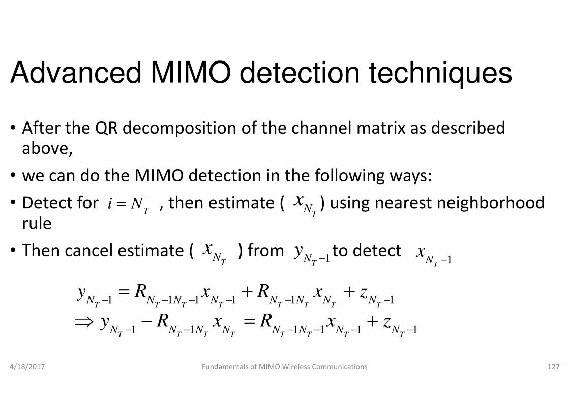
Advanced MIMO detection techniques
• After the QR decomposition of the channel matrix as described above,
• we can do the MIMO detection in the following ways:
• Detect for , then estimate ( ) using nearest neighborhood i N=• Detect for , then estimate ( ) using nearest neighborhood rule
• Then cancel estimate ( ) from to detect
4/18/2017 Fundamentals of MIMO Wireless Communications
Ti N=
TN
x
1 1 1 1 1 1
1 1 1 1 1 1
T T T T T T T T
T T T T T T T T
N N N N N N N N
N N N N N N N N
y R x R x z
y R x R x z
− − − − − −
− − − − − −
= + +
⇒ − = +
Advanced MIMO detection techniques
After the QR decomposition of the channel matrix as described
we can do the MIMO detection in the following ways:
Detect for , then estimate ( ) using nearest neighborhood xDetect for , then estimate ( ) using nearest neighborhood
Then cancel estimate ( ) from to detect
Fundamentals of MIMO Wireless Communications 127
TN
x
1T
Ny
− 1T
Nx
−
1 1 1 1 1 1
1 1 1 1 1 1
T T T T T T T T
T T T T T T T T
N N N N N N N N
N N N N N N N N
y R x R x z
y R x R x z
− − − − − −
− − − − − −
= + +
− = +

Advanced MIMO detection techniques
• If we have estimated correctly that means , thenT
Nx
1 1
1ˆ T T T T
T
N N N N
N
y R xx g
R
− −
−
− =
• where g is the slicing function
• Note that can be expressed as
4/18/2017 Fundamentals of MIMO Wireless Communications
1
1 1
ˆT
T T
N
N NR
−
− −
iy
N
ij
jijiiii xRxRyT
+= ∑+= 1
Advanced MIMO detection techniques
If we have estimated correctly that means , thenˆT T
N Nx x=
1 1ˆ
T T T TN N N N
y R x− −
Note that can be expressed as
Fundamentals of MIMO Wireless Communications 128
1 1
ˆ
T T− −
ij z+

Advanced MIMO detection techniques
• where xi is the current detected signal
• yi contains a lower level of interference than the received signal
• as the interference from xl for l<available estimates which are already detected available estimates which are already detected
• Hence the current signal xi can be estimated as
4/18/2017 Fundamentals of MIMO Wireless Communications
1ˆ
TN
i ij jj i
i
ii
y R x
x gR
= +
−
=
∑
Advanced MIMO detection techniques
is the current detected signal
contains a lower level of interference than the received signal r
for l<i can be cancelled from the available estimates which are already detected available estimates which are already detected
can be estimated as
Fundamentals of MIMO Wireless Communications 129
ˆi ij j
y R x

• Fig.
Illustration of Successive interference cancellation (SIC)
4/18/2017 Fundamentals of MIMO Wireless CommunicationsFundamentals of MIMO Wireless Communications 130
Advanced MIMO detection techniques
• The basic idea of successive interference cancellation (SIC) is to
• cancel the interference from the previous detected symbols
• as depicted in Fig.
• This will reduce the interference and • This will reduce the interference and
• hence increases effective SINR
4/18/2017 Fundamentals of MIMO Wireless Communications
Advanced MIMO detection techniques
The basic idea of successive interference cancellation (SIC) is to
cancel the interference from the previous detected symbols
This will reduce the interference and This will reduce the interference and
Fundamentals of MIMO Wireless Communications 131
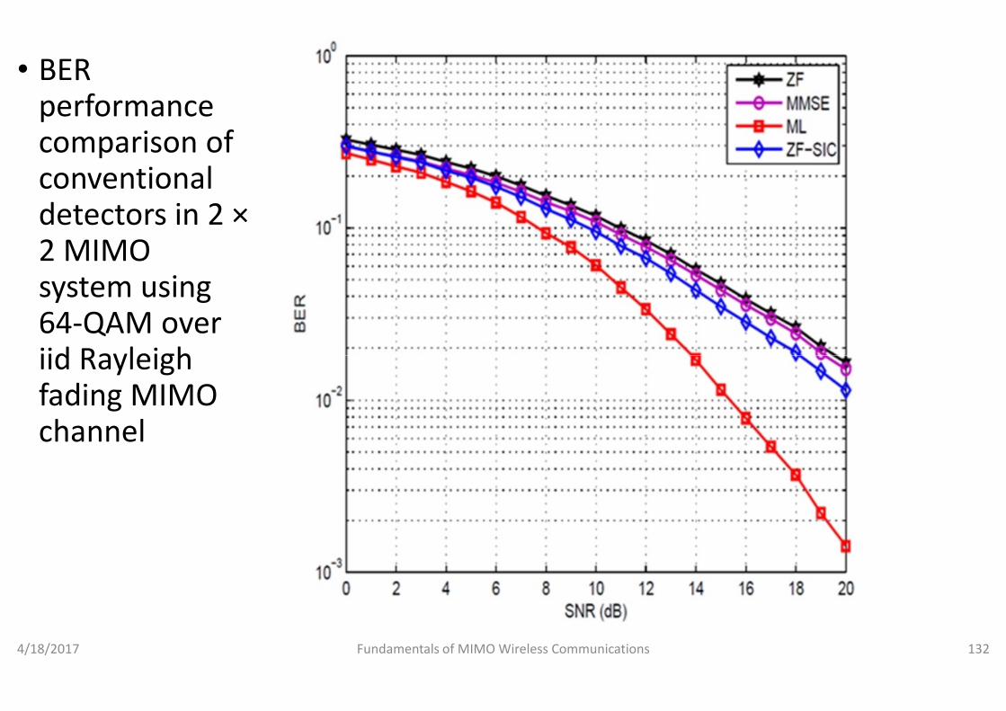
• BER performance comparison of conventional detectors in 2 ×2 MIMO system using 64-QAM over iid Rayleigh iid Rayleigh fading MIMO channel
4/18/2017 Fundamentals of MIMO Wireless CommunicationsFundamentals of MIMO Wireless Communications 132
Advanced MIMO detection techniques
• Fig. depicts the performance of various conventional detectors viz.
• ZF,
• MMSE,
• ML and • ML and
• ZF-SIC
• over iid Rayleigh fading MIMO channel
• As expected,
• ML has the best BER performance,
• then ZF-SIC, MMSE and ZF
4/18/2017 Fundamentals of MIMO Wireless Communications
Advanced MIMO detection techniques
Fig. depicts the performance of various conventional detectors viz.
Rayleigh fading MIMO channel
ML has the best BER performance,
Fundamentals of MIMO Wireless Communications 133

Advanced MIMO detection techniques
• Example 10.3
• Explain ZF-SIC for 3×3 MIMO system
• Solution:
• For N =N =3, we have• For NT=NR=3, we have
4/18/2017 Fundamentals of MIMO Wireless Communications
Advanced MIMO detection techniques
3 MIMO system
=⇒
+=
++=
+++=
3
33333
13231222
13132121111
ˆy
gx
zxRy
zxRxRy
zxRxRxRy
Fundamentals of MIMO Wireless Communications 134
−−=
−=
=⇒
11
32321211
22
32322
33
33
ˆˆˆ
ˆˆ
ˆ
R
xRxRygx
R
xRygx
Rgx

Advanced MIMO detection techniques
• Minimum-mean squared successive interference cancellationdetector
• We can see the equivalent ZF detection of MMSE detection
• by defining an extended channel matrix and received vector as • by defining an extended channel matrix and received vector as follows
4/18/2017 Fundamentals of MIMO Wireless Communications
=
=0
yy
I
H
H ext
s
ext
E
N0 ;
+ R. Bohnke, D. Wubben, V. Kuhn and K. D. Kammeyer
architectures,” in Proc. IEEE Proceedings of Global Conference on Telecommunications
CA, 2003.
Advanced MIMO detection techniques
mean squared successive interference cancellation
We can see the equivalent ZF detection of MMSE detection
by defining an extended channel matrix and received vector as by defining an extended channel matrix and received vector as
Fundamentals of MIMO Wireless Communications 135
−=
I
n
n
s
ext
E
N0;
Kammeyer, “Reduced complexity MMSE detection for BLAST
IEEE Proceedings of Global Conference on Telecommunications, San Francisco,

Advanced MIMO detection techniques
• where is the signal-to-noise ratio (SNR)0
SE
N
HHH N
N0ˆ
==
4/18/2017 Fundamentals of MIMO Wireless Communications
( )yHIHH
IIHrWs
H
s
H
ss
HHZF
E
N
E
NE
N
1
0
00ˆ
−
+=
==
Advanced MIMO detection techniques
noise ratio (SNR)
yH N0
1−
Fundamentals of MIMO Wireless Communications 136
0
yIH
Is
H
E
N0

Advanced MIMO detection techniques
• This is exactly what we do in the MMSE detector
• We can do the QR factorization of this new extended ZF detector and
• follow the same procedure of sequential detection
• which will behave like MMSE-SIC detector• which will behave like MMSE-SIC detector
• Conservation theorem
• sum of diversity gain (d) plus number of interferers ( ) equals the number of receive antennas (N
4/18/2017 Fundamentals of MIMO Wireless Communications
erNd + int+ J. R Barry, E. A. Lee and D. G. Messerschmitt, Digital Communications
Advanced MIMO detection techniques
This is exactly what we do in the MMSE detector
We can do the QR factorization of this new extended ZF detector and
follow the same procedure of sequential detection
SIC detectorSIC detector
) plus number of interferers ( ) equals NR)
Fundamentals of MIMO Wireless Communications 137
erNint
RN=Digital Communications, Kluwer Publications, 2010.
Advanced MIMO detection techniques
• Example
• Explain that ZF-SIC has higher diversity order than ZF using conservation theorem
• Note that ZF-SIC involves • Note that ZF-SIC involves
• nulling and
• cancelling operation
• simultaneously
• First nulling vector must null the N
4/18/2017 Fundamentals of MIMO Wireless Communications
Advanced MIMO detection techniques
SIC has higher diversity order than ZF using
vector must null the NT-1 interferers
Fundamentals of MIMO Wireless Communications 138
Advanced MIMO detection techniques
• From conservation theorem,
• the diversity order for first detection of 1
• Similarly, he diversity order for second detection of symbol is
+−
• Therefore, for detecting the symbol, the diversity order is
4/18/2017 Fundamentals of MIMO Wireless Communications
2+− TR NN
NN TR +−
Advanced MIMO detection techniques
the diversity order for first detection of 1st symbol is
Similarly, he diversity order for second detection of symbol is
1+− TR NN
Therefore, for detecting the symbol, the diversity order is
Fundamentals of MIMO Wireless Communications 139
2
k
Advanced MIMO detection techniques
• So the last symbol detected will have full diversity order
• Note that if any symbols are not detected correctly,
• this diversity order decreases
• To sum up, • To sum up,
• there is diversity order gain for ZF
4/18/2017 Fundamentals of MIMO Wireless Communications
Advanced MIMO detection techniques
So the last symbol detected will have full diversity order
Note that if any symbols are not detected correctly,
there is diversity order gain for ZF-SIC over ZF MIMO detectors
Fundamentals of MIMO Wireless Communications 140
Advanced MIMO detection techniques
• Example
• Explain that MMSE detector has higher diversity order than ZF using conservation theorem
• MMSE detectors ignores those interferers whose strength is below • MMSE detectors ignores those interferers whose strength is below noise floor level, thereby,
• the diversity order for MMSE detector can be expressed as
• where is the number of significant interferers
4/18/2017 Fundamentals of MIMO Wireless Communications
RN
effTN
Advanced MIMO detection techniques
Explain that MMSE detector has higher diversity order than ZF using
MMSE detectors ignores those interferers whose strength is below MMSE detectors ignores those interferers whose strength is below
the diversity order for MMSE detector can be expressed as
where is the number of significant interferers
Fundamentals of MIMO Wireless Communications 141
1+−effTN
Advanced MIMO detection techniques
• Hence the effective diversity order of MMSE detectors
• could be higher than the ZF detector
• Ordered successive interference cancellation detector
• In SIC, if the detected stream in one step is incorrect, • In SIC, if the detected stream in one step is incorrect,
• its subtraction from the received vector will increase the interference and
• results in performance degradation
• This is also known as error propagation
4/18/2017 Fundamentals of MIMO Wireless Communications
Advanced MIMO detection techniques
Hence the effective diversity order of MMSE detectors
could be higher than the ZF detector
Ordered successive interference cancellation detector
In SIC, if the detected stream in one step is incorrect, In SIC, if the detected stream in one step is incorrect,
its subtraction from the received vector will increase the
results in performance degradation
This is also known as error propagation
Fundamentals of MIMO Wireless Communications 142

Advanced MIMO detection techniques
• Hence the critical issue in ordering the detection of each stream
• so that error propagation is minimized
• There are techniques which combine
• ordered successive interference cancellation (OSIC) and • ordered successive interference cancellation (OSIC) and
• linear detection techniques like
• ZF-OSIC and
• MMSE-OSIC
4/18/2017 Fundamentals of MIMO Wireless Communications
Advanced MIMO detection techniques
Hence the critical issue in ordering the detection of each stream
so that error propagation is minimized
There are techniques which combine
ordered successive interference cancellation (OSIC) and ordered successive interference cancellation (OSIC) and
linear detection techniques like
Fundamentals of MIMO Wireless Communications 143
Advanced MIMO detection techniques
• The idea is to detect the signal with minimal error first
• so that the error propagation may be minimized
• In the process, we may decide the order in which
• we detect the signals by various criteria listed below:
• (a) Signal to noise interference ratio (SINR)• (a) Signal to noise interference ratio (SINR)
• Signals with the higher SINR are detected earlier than the other signals
• (b) Signal to noise ratio (SNR)
• Signals with the higher SNR are detected earlier than the other signals
4/18/2017 Fundamentals of MIMO Wireless Communications
Advanced MIMO detection techniques
The idea is to detect the signal with minimal error first
so that the error propagation may be minimized
In the process, we may decide the order in which
we detect the signals by various criteria listed below:
(a) Signal to noise interference ratio (SINR)(a) Signal to noise interference ratio (SINR)
Signals with the higher SINR are detected earlier than the other
Signals with the higher SNR are detected earlier than the other
Fundamentals of MIMO Wireless Communications 144
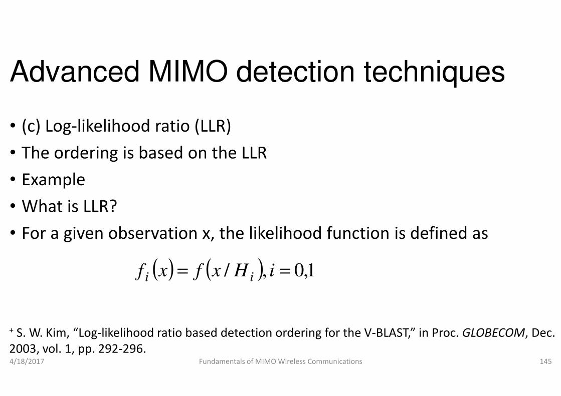
Advanced MIMO detection techniques
• (c) Log-likelihood ratio (LLR)
• The ordering is based on the LLR
• Example
• What is LLR?• What is LLR?
• For a given observation x, the likelihood function is defined as
4/18/2017 Fundamentals of MIMO Wireless Communications
( ) ( ),/ == iHxfxf ii
+ S. W. Kim, “Log-likelihood ratio based detection ordering for the V
2003, vol. 1, pp. 292-296.
Advanced MIMO detection techniques
For a given observation x, the likelihood function is defined as
Fundamentals of MIMO Wireless Communications 145
1,0=
likelihood ratio based detection ordering for the V-BLAST,” in Proc. GLOBECOM, Dec.

Advanced MIMO detection techniques
• The ML decision is to choose the hypothesis (either H
• that maximizes the likelihood function
( )00 HH
4/18/2017 Fundamentals of MIMO Wireless Communications
( ) ( )( )( )
1
1
0
1
01
1
0
0
H
xf
xfxf
H
xf<
>⇒
<
>
Advanced MIMO detection techniques
The ML decision is to choose the hypothesis (either H0 or H1)
that maximizes the likelihood function
( )0H
Fundamentals of MIMO Wireless Communications 146
( )( )( )
0ln1
1
0
1
0
H
xf
xfxLLR
<
>
=⇒

Advanced MIMO detection techniques
• Likelihood ratio
• Log likelihood ratio
( )( )xf
xf
1
0
( )( )
xf
xf
1
0ln
• let us consider a simple binary alphabet of
• So when we send 1 and -1, the received vectors are
4/18/2017 Fundamentals of MIMO Wireless Communications
( ) xf1
( ) rnhr =++= ;1
Advanced MIMO detection techniques
let us consider a simple binary alphabet of
1, the received vectors are
Fundamentals of MIMO Wireless Communications 147
{ }1 1,S = − +
( ) nh +−1
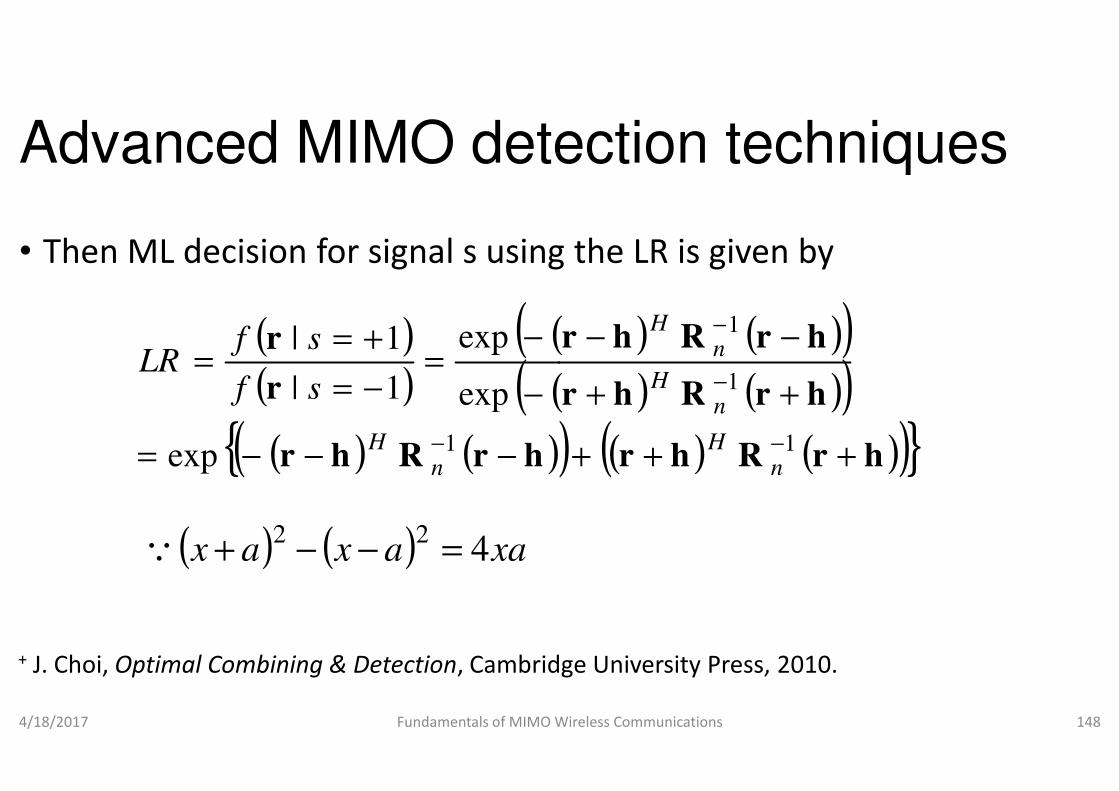
Advanced MIMO detection techniques
• Then ML decision for signal s using the LR is given by
( )( )
((((r
r
−
−=
−=
+==
exp
exp
1|
1|
sf
sfLR
4/18/2017 Fundamentals of MIMO Wireless Communications
( ) ((( ) ( )( ){ hrRhr
r
−−−=
−−=
−1exp
exp1|
nH
sf
( ) ( ) xaaxax 422
=−−+Q
+ J. Choi, Optimal Combining & Detection, Cambridge University Press, 2010
Advanced MIMO detection techniques
Then ML decision for signal s using the LR is given by
( ) ( ))( ) ( ))hrRhr
hrRhr
++
−−−
−
1
1
nH
nH
Fundamentals of MIMO Wireless Communications 148
( ) ( ))) ( ) ( )( )}hrRhr
hrRhr
+++
++
−1n
H
n
, Cambridge University Press, 2010.

Advanced MIMO detection techniques
• The sign of LLR is like ML detection (hard decision) and
• the absolute value of LLR will give an idea of how reliable is the
( ) {Re4ln == LRLLR
• the absolute value of LLR will give an idea of how reliable is the decision
• As we know that for V-BLAST detection (after have,
4/18/2017 Fundamentals of MIMO Wireless Communications
nw iii xy +=
+ Y. S. Cho, J. Kim, W. Y. Yang and C.-G. Kang, MIMO
Wiley, 2010.
Advanced MIMO detection techniques
The sign of LLR is like ML detection (hard decision) and
the absolute value of LLR will give an idea of how reliable is the
{ }rRh1Re −
nH
the absolute value of LLR will give an idea of how reliable is the
BLAST detection (after nulling operation), we
Fundamentals of MIMO Wireless Communications 149
MIMO-OFDM wireless communications using MATLAB,

Advanced MIMO detection techniques
• The LLR λi for xi (assume equiprobable
(( |
|ln
si
si
iyExP
yExP
−=
+==λ
• It can be shown that the bit error probability and LLR is related by
4/18/2017 Fundamentals of MIMO Wireless Communications
( |si yExP −=
( )xxPP iiie =≠=1
ˆ,
Advanced MIMO detection techniques
equiprobable BPSK symbols) is given by
))
( )2
0
Re4
i
is
i
i y
N
E
y
y
w=
It can be shown that the bit error probability and LLR is related by
Fundamentals of MIMO Wireless Communications 150
) 0 iiNy w
ieλ
+1
1

Advanced MIMO detection techniques
• Since the bit error probability decreases with increasing LLR,
• the detection ordering is to detect the component of
• that provides the largest firstiλ
4/18/2017 Fundamentals of MIMO Wireless Communications
Advanced MIMO detection techniques
Since the bit error probability decreases with increasing LLR,
the detection ordering is to detect the component of x
Fundamentals of MIMO Wireless Communications 151

Advanced MIMO detection techniques
• Fig. V-BLAST MIMO system
4/18/2017 Fundamentals of MIMO Wireless Communications
Advanced MIMO detection techniques
BLAST MIMO system
Fundamentals of MIMO Wireless Communications 152

Advanced MIMO detection techniques
• In the performance analysis,
• it is quite involved to find the exact performance analysis
• Hence, we will derive the
• upper and lower bound • upper and lower bound
• of the ZF-SIC detector’s performance
• Consider the I-O model of a V-BLAST MIMO system depicted in Fig.
• The received signal vector r for a narrowband MIMO channel be obtained as
4/18/2017 Fundamentals of MIMO Wireless Communications
= +r Hs n
Advanced MIMO detection techniques
it is quite involved to find the exact performance analysis
SIC detector’s performance
BLAST MIMO system depicted in Fig.
for a narrowband MIMO channel H can
Fundamentals of MIMO Wireless Communications 153

Advanced MIMO detection techniques
• We can also express channel matrix
= 1 2 N
H h h h
h
• where for
4/18/2017 Fundamentals of MIMO Wireless Communications
1
2
R
k
k
k
N k
h
h
h
=
h M 1 2, , ,T
k N= L
Advanced MIMO detection techniques
We can also express channel matrix H in terms of column vectors
T
1 2 NH h h hL
Fundamentals of MIMO Wireless Communications 154
T
, , ,T
k N
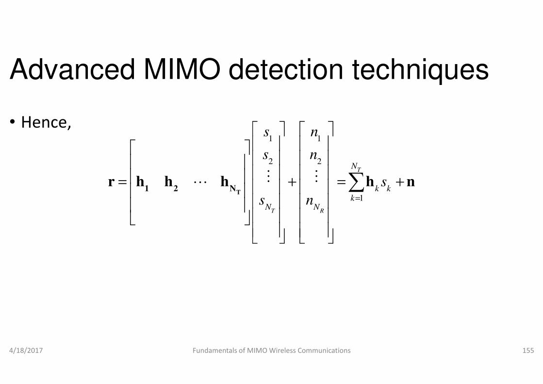
Advanced MIMO detection techniques
• Hence,1 1
2 2
s n
s n
s n
= + = +
T1 2 N
r h h h h nM ML
4/18/2017 Fundamentals of MIMO Wireless Communications
T RN N
s n
T1 2 N
Advanced MIMO detection techniques
1 1
2 2T
N
k k
s n
s n
s
s n =
= + = +
∑r h h h h nM M
Fundamentals of MIMO Wireless Communications 155
1
T R
k kk
N Ns n =
∑

Advanced MIMO detection techniques
• We will assume SINR based ordering which is optimal, i.e.,
• only the layer with highest SINR is detected in each recursion
• which gives the lowest SER in overall
• We will also assume that perfect SIC • We will also assume that perfect SIC
• PSIC which means that the cancelled interference are accurate
• Hence optimal ordered perfect ZF-
• will give the lower bound of ZF-
4/18/2017 Fundamentals of MIMO Wireless Communications
Advanced MIMO detection techniques
We will assume SINR based ordering which is optimal, i.e.,
only the layer with highest SINR is detected in each recursion
which gives the lowest SER in overall
We will also assume that perfect SIC We will also assume that perfect SIC
PSIC which means that the cancelled interference are accurate
-SIC detector (ZF-OOPSIC)
-OSIC
Fundamentals of MIMO Wireless Communications 156
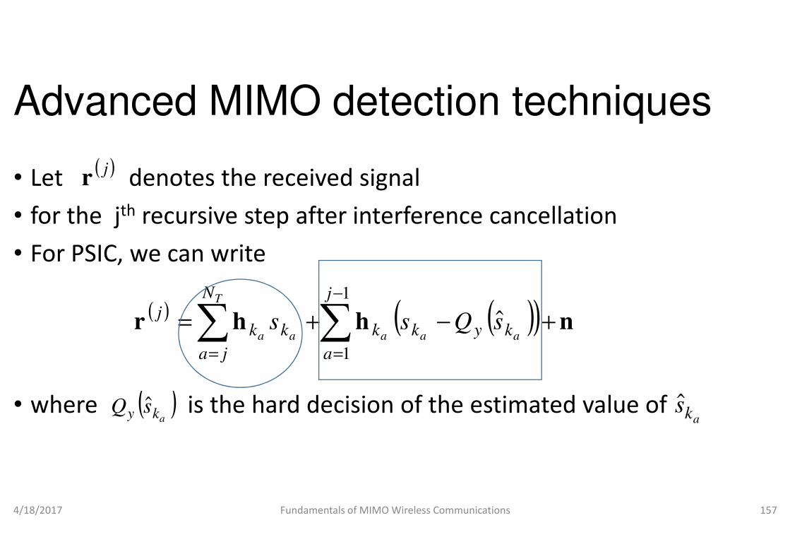
Advanced MIMO detection techniques
• Let denotes the received signal
• for the jth recursive step after interference cancellation
• For PSIC, we can write
( )jr
• where is the hard decision of the estimated value of
4/18/2017 Fundamentals of MIMO Wireless Communications
( ) (hhr += ∑∑−
==
1
1
j
a
k
N
ja
kkj
a
T
aas
( )aky sQ ˆ
Advanced MIMO detection techniques
Let denotes the received signal
recursive step after interference cancellation
is the hard decision of the estimated value of
Fundamentals of MIMO Wireless Communications 157
( )( ) n+− ˆkyk aa
sQs
aks

Advanced MIMO detection techniques
• In the above equation,
• the first summation term is for undetected symbols, and
• the second summation is the interfedetected symbolsdetected symbols
• For PSIC,
• the detected symbols are exactly
• what we have transmitted
4/18/2017 Fundamentals of MIMO Wireless Communications
Advanced MIMO detection techniques
the first summation term is for undetected symbols, and
terference cancellation of the already
Fundamentals of MIMO Wireless Communications 158
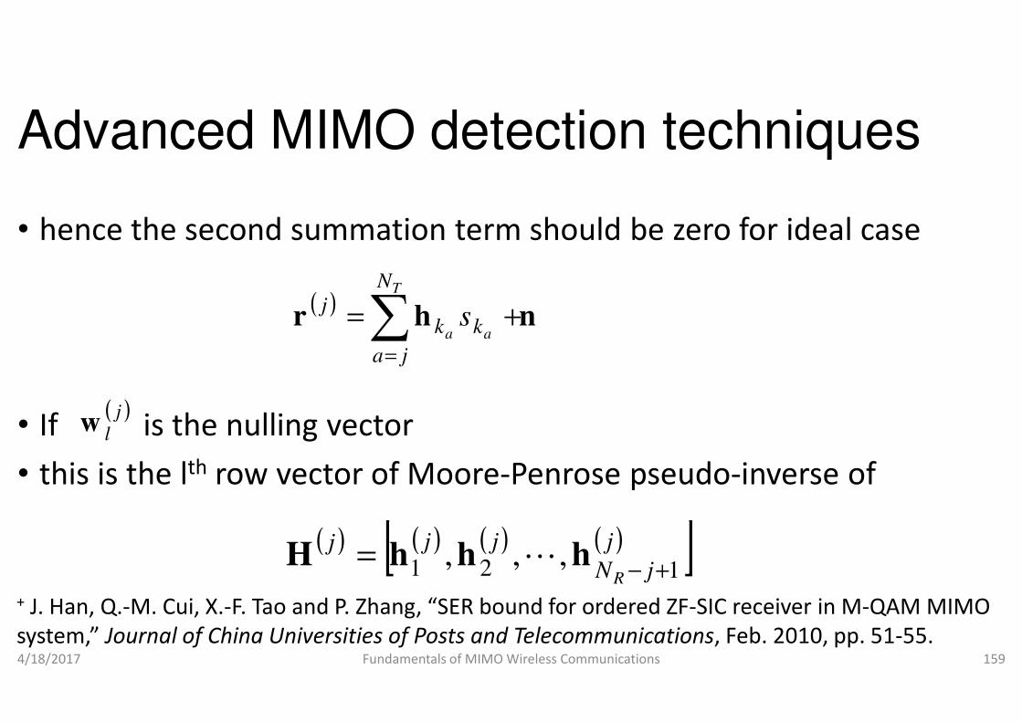
Advanced MIMO detection techniques
• hence the second summation term should be zero for ideal case
( )hr ∑
=
+=T
aa
N
ja
kkj
s
• If is the nulling vector
• this is the lth row vector of Moore-Penrose pseudo
4/18/2017 Fundamentals of MIMO Wireless Communications
= ja
( )j
lw
( ) ( ) ( )[ jjj21 ,= hhH
+ J. Han, Q.-M. Cui, X.-F. Tao and P. Zhang, “SER bound for ordered ZF
system,” Journal of China Universities of Posts and Telecommunications
Advanced MIMO detection techniques
hence the second summation term should be zero for ideal case
n+
Penrose pseudo-inverse of
Fundamentals of MIMO Wireless Communications 159
( ) ]j
jNR 1,,
+−hL
F. Tao and P. Zhang, “SER bound for ordered ZF-SIC receiver in M-QAM MIMO
Journal of China Universities of Posts and Telecommunications, Feb. 2010, pp. 51-55.
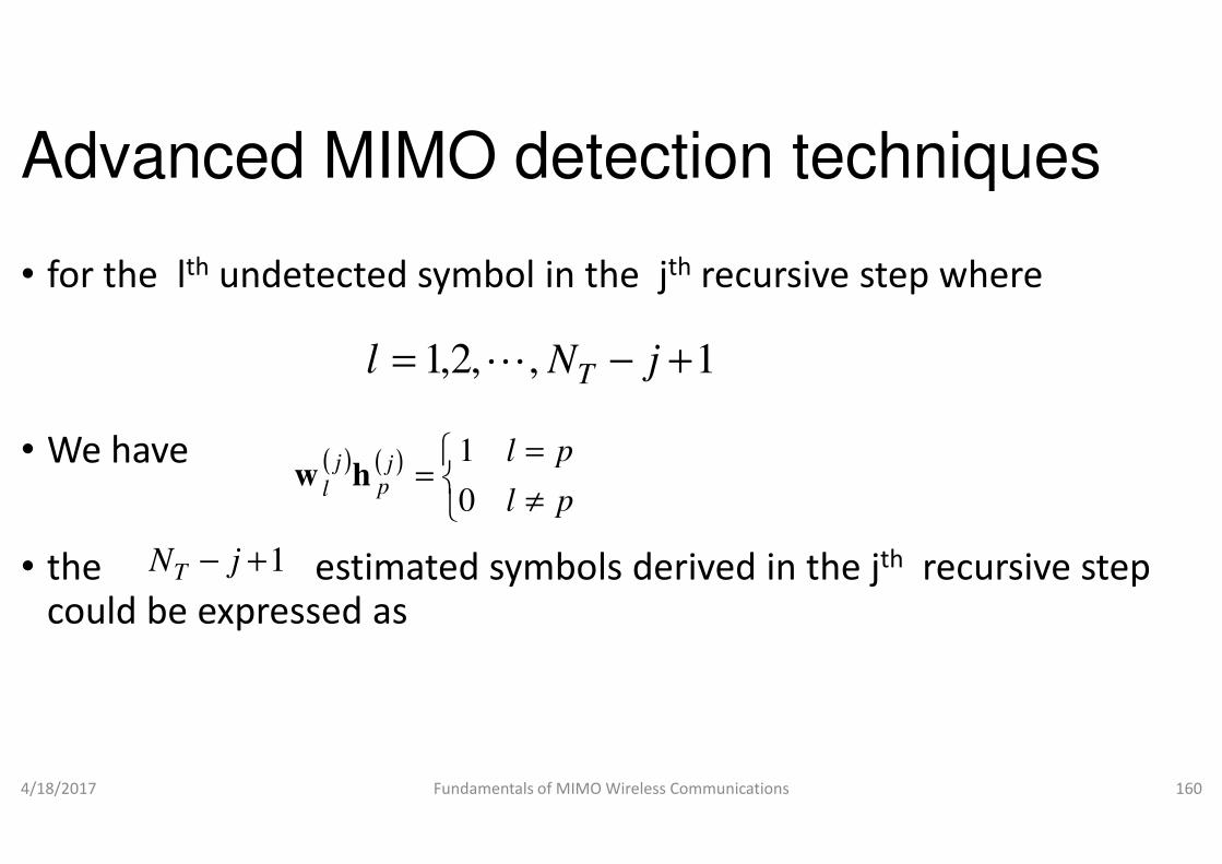
Advanced MIMO detection techniques
• for the lth undetected symbol in the
• We have
,,2,1 −= Nl TL
= pl1• We have
• the estimated symbols derived in the could be expressed as
4/18/2017 Fundamentals of MIMO Wireless Communications
( ) ( )
≠
==
pl
pljp
j
l 0
1hw
1+− jNT
Advanced MIMO detection techniques
undetected symbol in the jth recursive step where
1+− j
the estimated symbols derived in the jth recursive step
Fundamentals of MIMO Wireless Communications 160

Advanced MIMO detection techniques
• Therefore, the SINR of the lth undetected layer in the
( ) ( ) ( ) ( ) ( )wnhwrw
j
l
N
ja
kkj
ljj
l
j
lss
T
aa=
+== ∑
=
ˆ
• Therefore, the SINR of the lth undetected layer in the step is given by
4/18/2017 Fundamentals of MIMO Wireless Communications
( ) ( )( )
0
2
2
j
l
lj
l
NE
sESINR
nw
=
=
Advanced MIMO detection techniques
undetected layer in the jth recursive
) ( ) ( ) ( ) ( )nwnwhwh
j
llj
l
N
lkja
kkj
llj
lsss
T
a
aa+=++ ∑
≠= ,
undetected layer in the jth recursive
Fundamentals of MIMO Wireless Communications 161
( ) ( ) 2
0
2j
l
j
l
P
ww
γ=
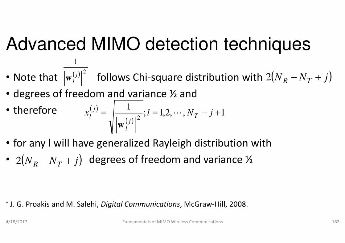
Advanced MIMO detection techniques
• Note that follows Chi-square distribution with
• degrees of freedom and variance ½ and
• therefore
( ) 2
1
j
lw
( )
( ),2,1;
12
== lxj
j
l
w
• for any l will have generalized Rayleigh distribution with
• degrees of freedom and variance ½
4/18/2017 Fundamentals of MIMO Wireless Communications
( )j
lw
( )jNN TR +−2
+ J. G. Proakis and M. Salehi, Digital Communications
Advanced MIMO detection techniques
square distribution with
degrees of freedom and variance ½ and
( )jNN TR +−2
1, +− jNTL
for any l will have generalized Rayleigh distribution with
degrees of freedom and variance ½
Fundamentals of MIMO Wireless Communications 162
Digital Communications, McGraw-Hill, 2008.
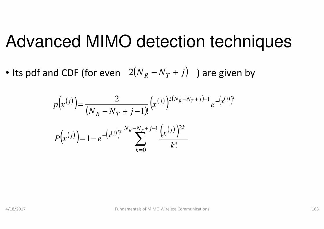
Advanced MIMO detection techniques
• Its pdf and CDF (for even ) are given by( NN R −2
( )( )( )
((!1
2 j
TR
jx
jNNxp
−+−=
4/18/2017 Fundamentals of MIMO Wireless Communications
( )!1TR jNN −+−
( )( ) ( )( ) (∑
−+−
=
−−=
1
0
12
jNN
k
xjTR
j
exP
Advanced MIMO detection techniques
and CDF (for even ) are given by)jNT +
) ) ( ) ( )( )212 jTR xjNN
e−−+−
Fundamentals of MIMO Wireless Communications 163
( )( )2
!
kj
k
x
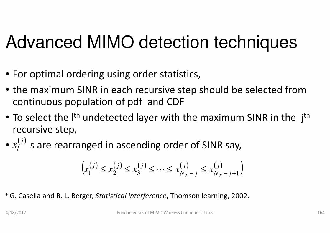
Advanced MIMO detection techniques
• For optimal ordering using order statistics,
• the maximum SINR in each recursive step should be selected from continuous population of pdf and CDF
• To select the lth undetected layer with the maximum SINR in the • To select the lth undetected layer with the maximum SINR in the recursive step,
• s are rearranged in ascending order of SINR say,
4/18/2017 Fundamentals of MIMO Wireless Communications
( )jlx
( ) ( ) ( )( jjjxxx 321 ≤≤≤ L
+ G. Casella and R. L. Berger, Statistical interference
Advanced MIMO detection techniques
For optimal ordering using order statistics,
the maximum SINR in each recursive step should be selected from and CDF
undetected layer with the maximum SINR in the jthundetected layer with the maximum SINR in the jth
s are rearranged in ascending order of SINR say,
Fundamentals of MIMO Wireless Communications 164
( ) ( ) )jjN
jjN TT
xx1+−− ≤≤L
Statistical interference, Thomson learning, 2002.
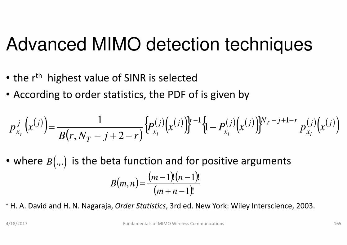
Advanced MIMO detection techniques
• the rth highest value of SINR is selected
• According to order statistics, the PDF of is given by
( )( ) ( )({ jjjxPxp =
1
• where is the beta function and for positive arguments
4/18/2017 Fundamentals of MIMO Wireless Communications
( )( )( )
( )({ j
xT
jj
xxP
rjNrBxp
lr −+−=
2,
1
( ).,.B
( ) ( )(
!1,
+
−=
nm
mnmB
+ H. A. David and H. N. Nagaraja, Order Statistics, 3rd ed. New York: Wiley
Advanced MIMO detection techniques
highest value of SINR is selected
According to order statistics, the PDF of is given by
( ))} ( ) ( )( ){ } ( ) ( )( )jjrjNjjrjxpxP
T −+−−−
111
where is the beta function and for positive arguments
Fundamentals of MIMO Wireless Communications 165
( ))} ( ) ( )( ){ } ( ) ( )( )jj
x
rjNjj
x
rjxpxP
l
T
l
−+−−−
111
( ))!1
!1!
−
−
n
n
, 3rd ed. New York: Wiley Interscience, 2003.
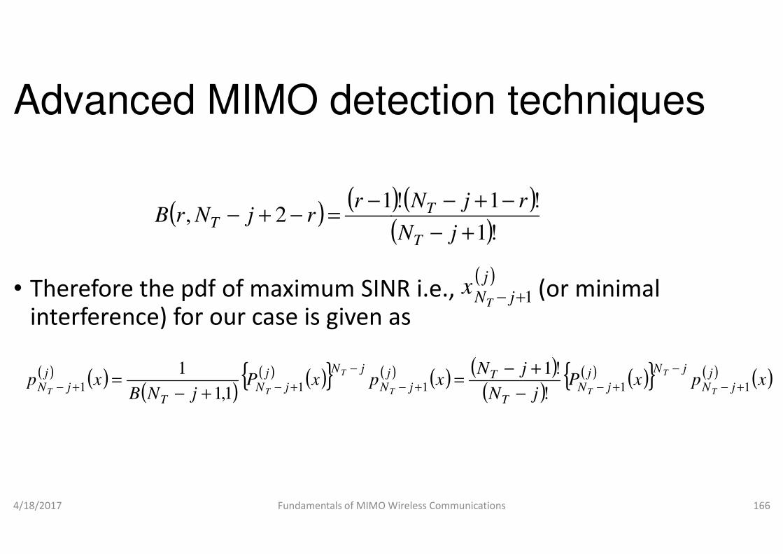
Advanced MIMO detection techniques
• Therefore the pdf of maximum SINR i.e., (or minimal
( ) ( )(
12,
−=−+−
rrjNrB T
• Therefore the pdf of maximum SINR i.e., (or minimal interference) for our case is given as
4/18/2017 Fundamentals of MIMO Wireless Communications
( ) ( )( )
( ) ( ){ } (pxP
jNBxp
j
N
jNj
jNT
j
jN T
T
TT 11 1,1
1 −
+−+− +−=
Advanced MIMO detection techniques
of maximum SINR i.e., (or minimal
) ( )( )!1
!1!1
+−
−+−
jN
rjN
T
T
( )jxof maximum SINR i.e., (or minimal
interference) for our case is given as
Fundamentals of MIMO Wireless Communications 166
( )j
jNTx
1+−
) ( ) ( )( )
( ) ( ){ } ( ) ( )xpxPjN
jNx
j
jN
jNj
jNT
Tj T
T
TT 111 !
!1+−
−
+−+− −
+−=

Advanced MIMO detection techniques
• The pdf and cdf of SINR of any undetected layer for our case are
( )( )( 1
2
TR
j
jNNxp
−+−=
4/18/2017 Fundamentals of MIMO Wireless Communications
( 1TR jNN −+−
( )( ) ( )( ) ∑−
=
−−=0
12
NN
k
xjTR
j
exP
Advanced MIMO detection techniques
of SINR of any undetected layer for our case are( )j
x
)( )( ) ( ) ( )( )212
!1
jTR xjNNj
ex−−+−
Fundamentals of MIMO Wireless Communications 167
)!1
( )( )∑
−+ 1
0
2
!
j kj
k
x

Advanced MIMO detection techniques
• Hence, the pdf of maximum SINR substituting is
• The CEP of M-QAM could be expressed as
x
( ) ( )1
1!
12 TjjN
eq
jNxp
T +−
−
+−=
• The CEP of M-QAM could be expressed as
4/18/2017 Fundamentals of MIMO Wireless Communications
( ) ( )
( )
−−
−
−=
−
−=
11
12
3112
1421
14|
2
2
erfcMM
SINRerfc
M
SINRgQM
SINREP QAMb
Advanced MIMO detection techniques
of maximum SINR substituting is
QAM could be expressed as
( )jx qjNN TR =−+− 1
22 1
0
2
!
xq
jNq
k
kx
exk
xe
T
−−
−
=
−
∑
QAM could be expressed as
Fundamentals of MIMO Wireless Communications 168
( )( )
( )
−
−=
−
12
3
12
3;2
11 2
2
M
SINR
MgSINRgQ
MQAMQAM

Advanced MIMO detection techniques
• where erfc is the complementary error function defined as
( ) ∫∞
− ==
x
ydyexerfc
2 2
π
4/18/2017 Fundamentals of MIMO Wireless Communications
xπ
( ) = ∫∞
−
2
1
0
2
2
dyexQ
y
π
+ G. L. Stuber, Principles of Mobile Communication,
Advanced MIMO detection techniques
is the complementary error function defined as
( )−= xerf1
Fundamentals of MIMO Wireless Communications 169
=
22
1 xerfc
, Kluwer Academic Publishers, 2001.

Advanced MIMO detection techniques
• There are NT layers to be detected
• we need to sum and average the probability of error for all layers
• The SER for M-QAM could be obtained as
4/18/2017 Fundamentals of MIMO Wireless Communications
( )
( )(EPN
PN
EP
T
T
N
j
jOOPSICZFb
T
N
jT
OOPSICZFb
∑∫
∑
=
∞
−
=
−
=
=
1 0
1
1
1
Advanced MIMO detection techniques
we need to sum and average the probability of error for all layers
QAM could be obtained as
Fundamentals of MIMO Wireless Communications 170
( )( )
) ( ) ( )dxxpSINRE
EP
T
j
jN
jOOPSICZFb
+−
−
1/
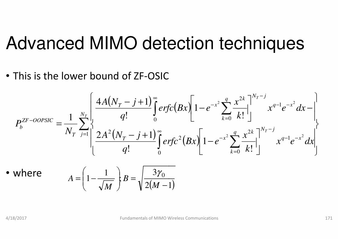
Advanced MIMO detection techniques
• This is the lower bound of ZF-OSIC
( )
∑∫∞
−
+−
=TN
T
OOPSICZF
erfcq
jNA
P0
!
14
1
• where
4/18/2017 Fundamentals of MIMO Wireless Communications
( )∑
∫=
∞
−
+−=
jT
T
OOPSICZF
b
erfcq
jNA
q
NP
1
0
2
0
!
12
!1
( 12
3;
11 0
−=
−=
MB
MA
γ
Advanced MIMO detection techniques
( ) ∑ −−
−
=
−
−
−
T
xq
jNq
k
kx dxex
k
xeBxerfc 1
0
222
!1
Fundamentals of MIMO Wireless Communications 171
( ) ∑ −−
−
=
−
=
−
T
xq
jNq
k
kx
k
dxexk
xeBxerfc
k
1
0
22
0
22
!1
!
)1

Advanced MIMO detection techniques
• For upper bound we can calculate the SER of ZF without SIC
• since in ZF we do not do the interference cancellation
• probability of error will be higher for this case than the ZF
• We can write SINR for ZF as• We can write SINR for ZF as
4/18/2017 Fundamentals of MIMO Wireless Communications
( )
( ) 2
0
j
jSINR
w
γ=
Advanced MIMO detection techniques
For upper bound we can calculate the SER of ZF without SIC
since in ZF we do not do the interference cancellation
probability of error will be higher for this case than the ZF-OSIC
Fundamentals of MIMO Wireless Communications 172
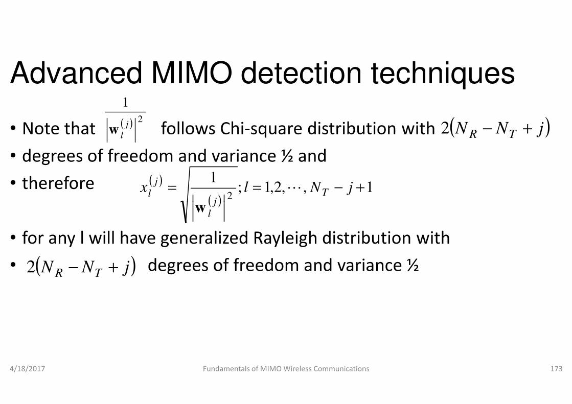
Advanced MIMO detection techniques
• Note that follows Chi-square distribution with
• degrees of freedom and variance ½ and
• therefore
( ) 2
1
j
lw
( )
( ),2,1;
12
== lxj
j
l
w
• for any l will have generalized Rayleigh distribution with
• degrees of freedom and variance ½
4/18/2017 Fundamentals of MIMO Wireless Communications
( )j
lw
( )jNN TR +−2
Advanced MIMO detection techniques
square distribution with
degrees of freedom and variance ½ and
( )jNN TR +−2
1, +− jNTL
for any l will have generalized Rayleigh distribution with
degrees of freedom and variance ½
Fundamentals of MIMO Wireless Communications 173

Advanced MIMO detection techniques
• Its pdf and CDF (for even ) are given by( NN R −2
( )( )( )
((!1
2 j
TR
jx
jNNxp
−+−=
4/18/2017 Fundamentals of MIMO Wireless Communications
( )!1TR jNN −+−
( )( ) ( )( ) (∑
−+−
=
−−=
1
0
12
jNN
k
xjTR
j
exP
Advanced MIMO detection techniques
and CDF (for even ) are given by)jNT +
) ) ( ) ( )( )212 jTR xjNN
e−−+−
Fundamentals of MIMO Wireless Communications 174
( )( )2
!
kj
k
x

Advanced MIMO detection techniques
• Therefore, for M-QAM, the SER for ZF for Nby
( ) ( ) ( ) ( ) ( )EPEPN
EPjZF
b
NjZF
bT
ZFb
T1∑ ==
4/18/2017 Fundamentals of MIMO Wireless Communications
( ) ( )
( )( )( ) ( ) ( )
dueuBuerfcNN
A
duupSINREP
N
uNN
TR
ZFb
b
j
bT
TR212
0
0
1
!
4
/
−+−∞
∞
=
∫
∫
∑
−−
=
=
Advanced MIMO detection techniques
QAM, the SER for ZF for NT layer detection is given
Fundamentals of MIMO Wireless Communications 175
( )( )( ) ( ) ( )
dueuBuerfcNN
A uNN
TR
TR212
0
22
!
2 −+−∞
∫−−

Advanced MIMO detection techniques
• SER for ZF-OSIC is bounded as
• Lattice reduction based detector
( ) PEPOSICZF
bOOPSICZF
b ≤ −−
• Lattice reduction based detector
• One of the major issues with linear detectors
• we have considered so far was the noise
• This effect becomes more pronounced
• when the channel matrix is not well
4/18/2017 Fundamentals of MIMO Wireless Communications
Advanced MIMO detection techniques
( ) ( )EPEZF
bOSIC ≤
One of the major issues with linear detectors
have considered so far was the noise enhancement
effect becomes more pronounced
the channel matrix is not well behaved
Fundamentals of MIMO Wireless Communications 176

Advanced MIMO detection techniques
• Lattice reduction algorithm could be employed
• to reduce the condition number of channel
• bring it closer to 1
• The condition number of a matrix is defined as • The condition number of a matrix is defined as
• the ratio of the largest and smallest singular value of the
• The L2-norm of a matrix equals its largest singular value
• the L2-norm of inverse of a matrix equals the reciprocal of the smallest singular value
4/18/2017 Fundamentals of MIMO Wireless Communications
Advanced MIMO detection techniques
Lattice reduction algorithm could be employed
reduce the condition number of channel matrix
The condition number of a matrix is defined as The condition number of a matrix is defined as
ratio of the largest and smallest singular value of the matrix
norm of a matrix equals its largest singular value
norm of inverse of a matrix equals the reciprocal of the
Fundamentals of MIMO Wireless Communications 177

Advanced MIMO detection techniques
• the condition number of matrix
• Hence for real orthogonal matrices
( )2
1
2min
max ≥== −HHH
σ
σcond
• Hence for real orthogonal matrices
• the condition number is one
• and no noise amplification for linear detectors
• Hence the matched filter and ZF are equivalent since
4/18/2017 Fundamentals of MIMO Wireless Communications
( ) HHHHHHH =
−1
+ V. Kuhn, Wireless Communications over MIMO channels
Advanced MIMO detection techniques
Hence for real orthogonal matrices with
1
T=−1Hence for real orthogonal matrices with
no noise amplification for linear detectors
Hence the matched filter and ZF are equivalent since
Fundamentals of MIMO Wireless Communications 178
THH =−1
H
Wireless Communications over MIMO channels, John Wiley & Sons, 2006.
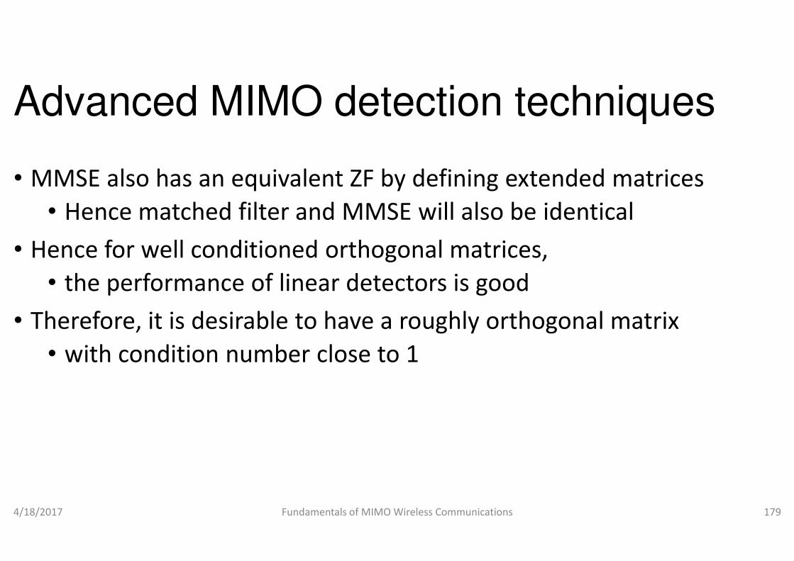
Advanced MIMO detection techniques
• MMSE also has an equivalent ZF by defining extended
• Hence matched filter and MMSE will also be
• Hence for well conditioned orthogonal matrices,
• the performance of linear detectors is • the performance of linear detectors is
• Therefore, it is desirable to have a roughly orthogonal matrix
• with condition number close to 1
4/18/2017 Fundamentals of MIMO Wireless Communications
Advanced MIMO detection techniques
MMSE also has an equivalent ZF by defining extended matrices
matched filter and MMSE will also be identical
Hence for well conditioned orthogonal matrices,
performance of linear detectors is goodperformance of linear detectors is good
, it is desirable to have a roughly orthogonal matrix
condition number close to 1
Fundamentals of MIMO Wireless Communications 179

Advanced MIMO detection techniques
• Lattice is regular arrangements of points in Euclidean space
• Using the basis vectors
• we can generate the lattice points in 2
( )11 0,b ( )2
0 1,b
• we can generate the lattice points in 2
• They generate all the intersection points of the grid also known as lattice points
• Similarly, using new basis vectors
4/18/2017 Fundamentals of MIMO Wireless Communications
( ),1,121'1 bbbb +=
Advanced MIMO detection techniques
of points in Euclidean space
can generate the lattice points in 2-D space as depicted in Fig. (a) can generate the lattice points in 2-D space as depicted in Fig. (a)
They generate all the intersection points of the grid also known as
Fundamentals of MIMO Wireless Communications 180
( )1,22 21'2 bbb +=
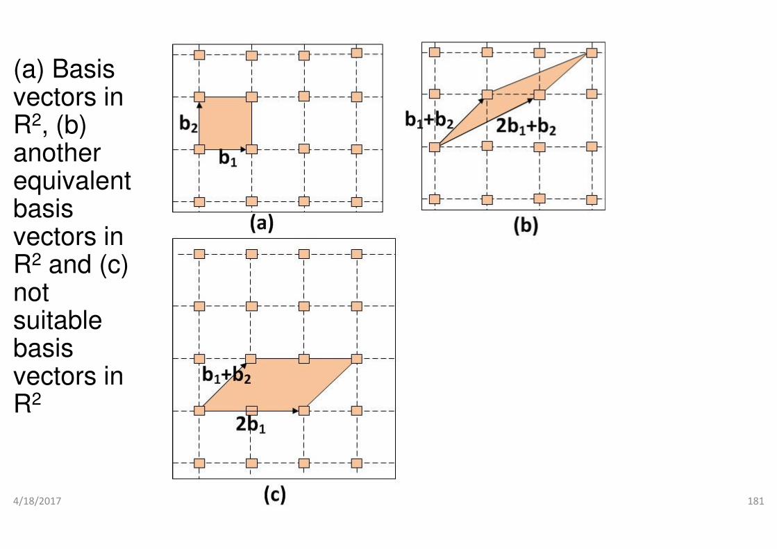
(a) Basis vectors in R2, (b) another equivalent basis vectors in R2 and (c) R and (c) not suitable basis vectors in R2
4/18/2017 Fundamentals of MIMO Wireless CommunicationsFundamentals of MIMO Wireless Communications 181
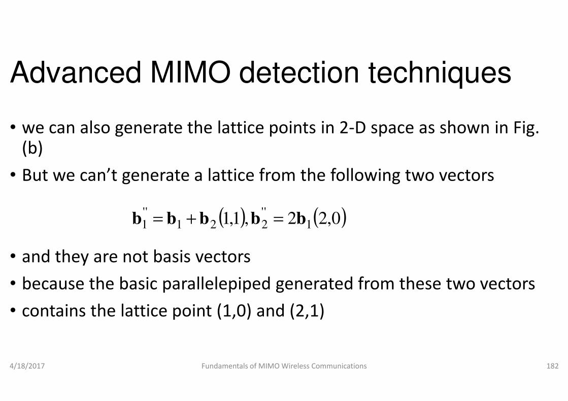
Advanced MIMO detection techniques
• we can also generate the lattice points in 2(b)
• But we can’t generate a lattice from the following two
• and they are not basis vectors
• because the basic parallelepiped generated from these two vectors
• contains the lattice point (1,0) and (2,1)
4/18/2017 Fundamentals of MIMO Wireless Communications
( ),1,1''221
''1 bbbb =+=
Advanced MIMO detection techniques
we can also generate the lattice points in 2-D space as shown in Fig.
But we can’t generate a lattice from the following two vectors
the basic parallelepiped generated from these two vectors
the lattice point (1,0) and (2,1)
Fundamentals of MIMO Wireless Communications 182
( )0,22 1b

Advanced MIMO detection techniques
• Example
• What is a lattice?
• A lattice L (regularly arranged arrays of points) is a set of vectors
• that are obtained by the integer linear combination of • that are obtained by the integer linear combination of
• a set of linearly independent vectors known as basis vectors
4/18/2017 Fundamentals of MIMO Wireless Communications
1 2, , ,
k = B b b bL
Advanced MIMO detection techniques
arranged arrays of points) is a set of vectors
are obtained by the integer linear combination of are obtained by the integer linear combination of
set of linearly independent vectors known as basis vectors
Fundamentals of MIMO Wireless Communications 183
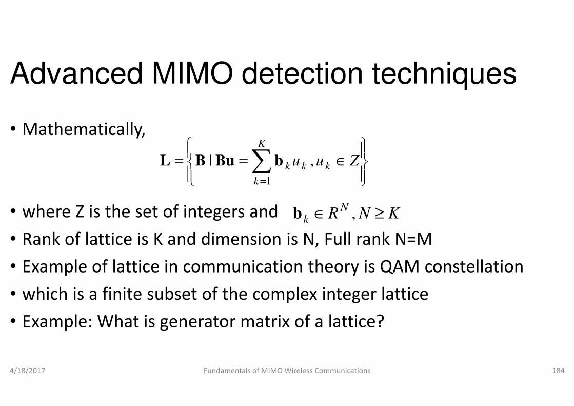
Advanced MIMO detection techniques
• Mathematically,
• where Z is the set of integers and
== ∑=
K
k
k
1
| bBuBL
• where Z is the set of integers and
• Rank of lattice is K and dimension is N, Full rank N=M
• Example of lattice in communication theory is QAM constellation
• which is a finite subset of the complex integer
• Example: What is generator matrix of a lattice?
4/18/2017 Fundamentals of MIMO Wireless Communications
Advanced MIMO detection techniques
∈kkk Zuu ,
N ≥∈
Rank of lattice is K and dimension is N, Full rank N=M
of lattice in communication theory is QAM constellation
is a finite subset of the complex integer lattice
is generator matrix of a lattice?
Fundamentals of MIMO Wireless Communications 184
KNRN
k ≥∈ ,b
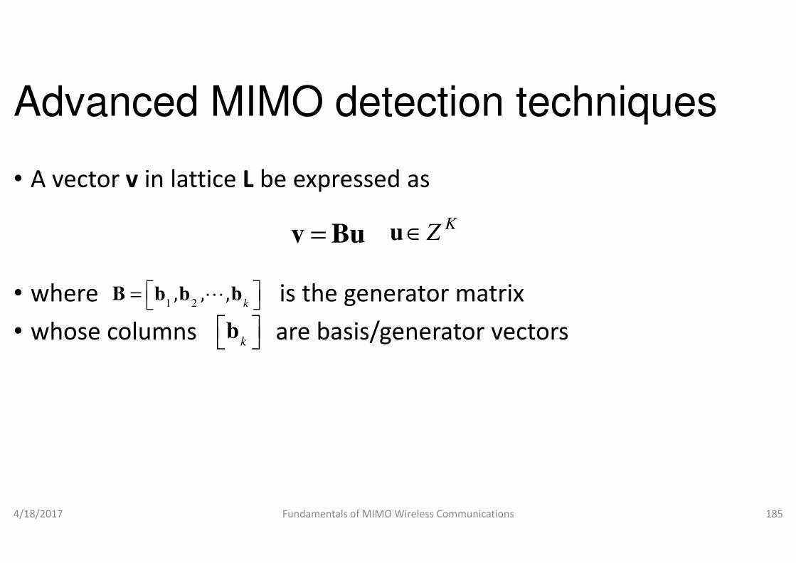
Advanced MIMO detection techniques
• A vector v in lattice L be expressed
• where is the generator matrix
=v Bu u
, , , =• where is the generator matrix
• whose columns are basis/generator vectors
4/18/2017 Fundamentals of MIMO Wireless Communications
1 2, , ,
k = B b b bL
k b
Advanced MIMO detection techniques
be expressed as
the generator matrix
KZ∈u
the generator matrix
basis/generator vectors
Fundamentals of MIMO Wireless Communications 185

Advanced MIMO detection techniques
• What is a unimodular matrix?
• A square matrix
• whose determinant is ±1 is called as
• An integer matrix U (whose elements are integer) • An integer matrix U (whose elements are integer)
• whose determinant is ±1 is called as integer
• It is quite possible that for the same lattice
• there could be two different generator matrices
• In that case,
4/18/2017 Fundamentals of MIMO Wireless Communications
21= B UB
Advanced MIMO detection techniques
1 is called as unimodular
(whose elements are integer) (whose elements are integer)
1 is called as integer unimodular
It is quite possible that for the same lattice L,
there could be two different generator matrices B1 and B2
Fundamentals of MIMO Wireless Communications 186
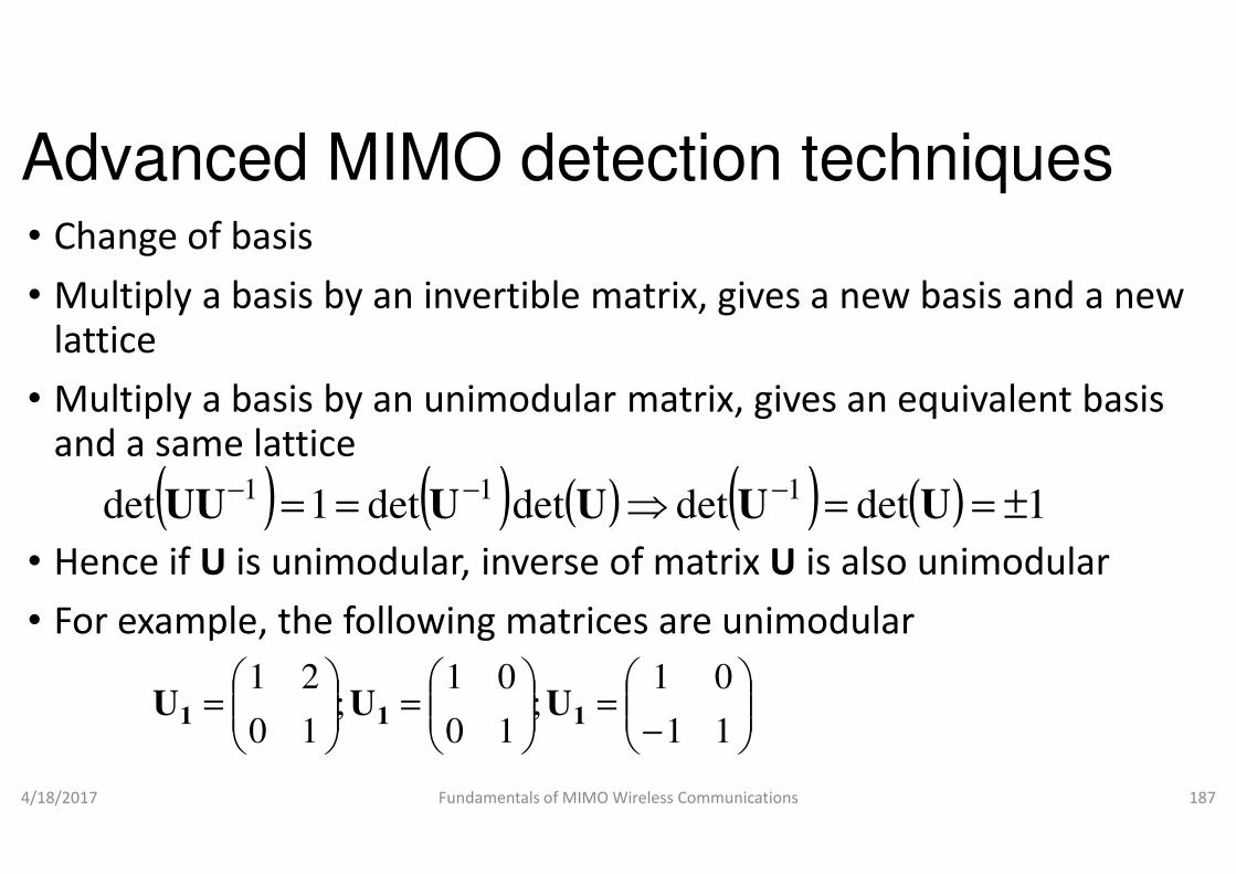
Advanced MIMO detection techniques• Change of basis
• Multiply a basis by an invertible matrix, gives a new basis and a new lattice
• Multiply a basis by an unimodularand a same latticeand a same lattice
• Hence if U is unimodular, inverse of matrix
• For example, the following matrices are
4/18/2017 Fundamentals of MIMO Wireless Communications
( ) ( ) ( )detdet1det11 == −−
UUUU
=
=
= ;
10
01;
10
21111 UUU
Advanced MIMO detection techniques
Multiply a basis by an invertible matrix, gives a new basis and a new
matrix, gives an equivalent basis
, inverse of matrix U is also unimodular
For example, the following matrices are unimodular
Fundamentals of MIMO Wireless Communications 187
) ( ) ( ) 1detdet1 ±==⇒ −
UU
− 11
01
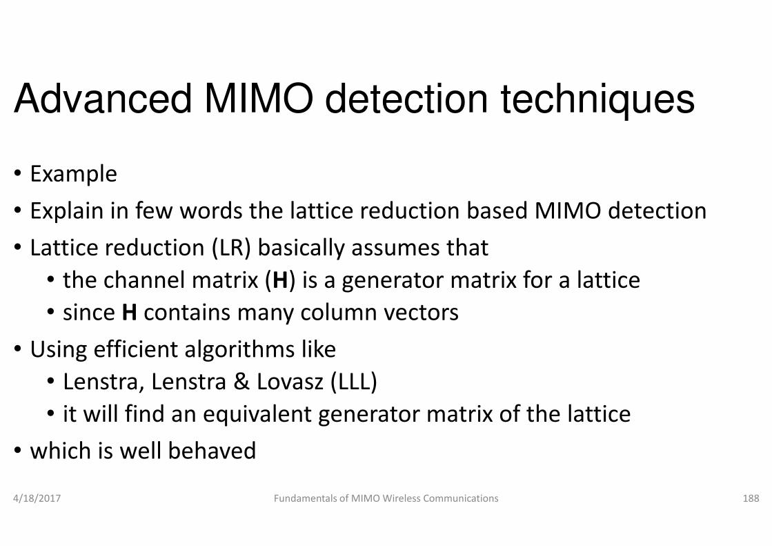
Advanced MIMO detection techniques
• Example
• Explain in few words the lattice reduction based MIMO detection
• Lattice reduction (LR) basically assumes that
• the channel matrix (H) is a generator matrix for a lattice • the channel matrix (H) is a generator matrix for a lattice
• since H contains many column vectors
• Using efficient algorithms like
• Lenstra, Lenstra & Lovasz (LLL)
• it will find an equivalent generator matrix of the lattice
• which is well behaved
4/18/2017 Fundamentals of MIMO Wireless Communications
Advanced MIMO detection techniques
Explain in few words the lattice reduction based MIMO detection
Lattice reduction (LR) basically assumes that
) is a generator matrix for a lattice ) is a generator matrix for a lattice
contains many column vectors
it will find an equivalent generator matrix of the lattice
Fundamentals of MIMO Wireless Communications 188

Advanced MIMO detection techniques
• We will apply the MIMO detection techniques to
• the new well behaved equivalent
• Sub-optimal MIMO detectors like
• ZF, ZF-SIC are surprisingly efficient • ZF, ZF-SIC are surprisingly efficient
• when they are employed on a reduced basis
• since the equivalent channel G
• hence the noise enhancement will be minimized
4/18/2017 Fundamentals of MIMO Wireless Communications
Advanced MIMO detection techniques
We will apply the MIMO detection techniques to
lent generator matrix of the channel
SIC are surprisingly efficient SIC are surprisingly efficient
when they are employed on a reduced basis
will be better behaved and
hence the noise enhancement will be minimized
Fundamentals of MIMO Wireless Communications 189

Advanced MIMO detection techniques
• Diversity order of MIMO detection:
• ZF�MMSE�SIC�ML
• Diversity order of LR based ZF/MMSE linear detector is the same as
• achieved by ML detector which is N for N• achieved by ML detector which is N for N
4/18/2017 Fundamentals of MIMO Wireless Communications
+ X. Ma and W. Zhang, “Performance analysis of MIMO systems with lattice
equalization,” IEEE Trans. Comm., vol. 56, no. 2, Feb. 2008, pp. 309
Advanced MIMO detection techniques
Diversity order of MIMO detection:
Diversity order of LR based ZF/MMSE linear detector is the same as
achieved by ML detector which is N for N×N MIMO systemsachieved by ML detector which is N for N×N MIMO systems
Fundamentals of MIMO Wireless Communications 190
X. Ma and W. Zhang, “Performance analysis of MIMO systems with lattice-reduction aided linear
, vol. 56, no. 2, Feb. 2008, pp. 309-318.
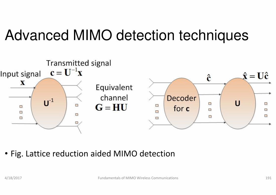
Advanced MIMO detection techniques
• Fig. Lattice reduction aided MIMO detection
4/18/2017 Fundamentals of MIMO Wireless Communications
Advanced MIMO detection techniques
Fig. Lattice reduction aided MIMO detection
Fundamentals of MIMO Wireless Communications 191
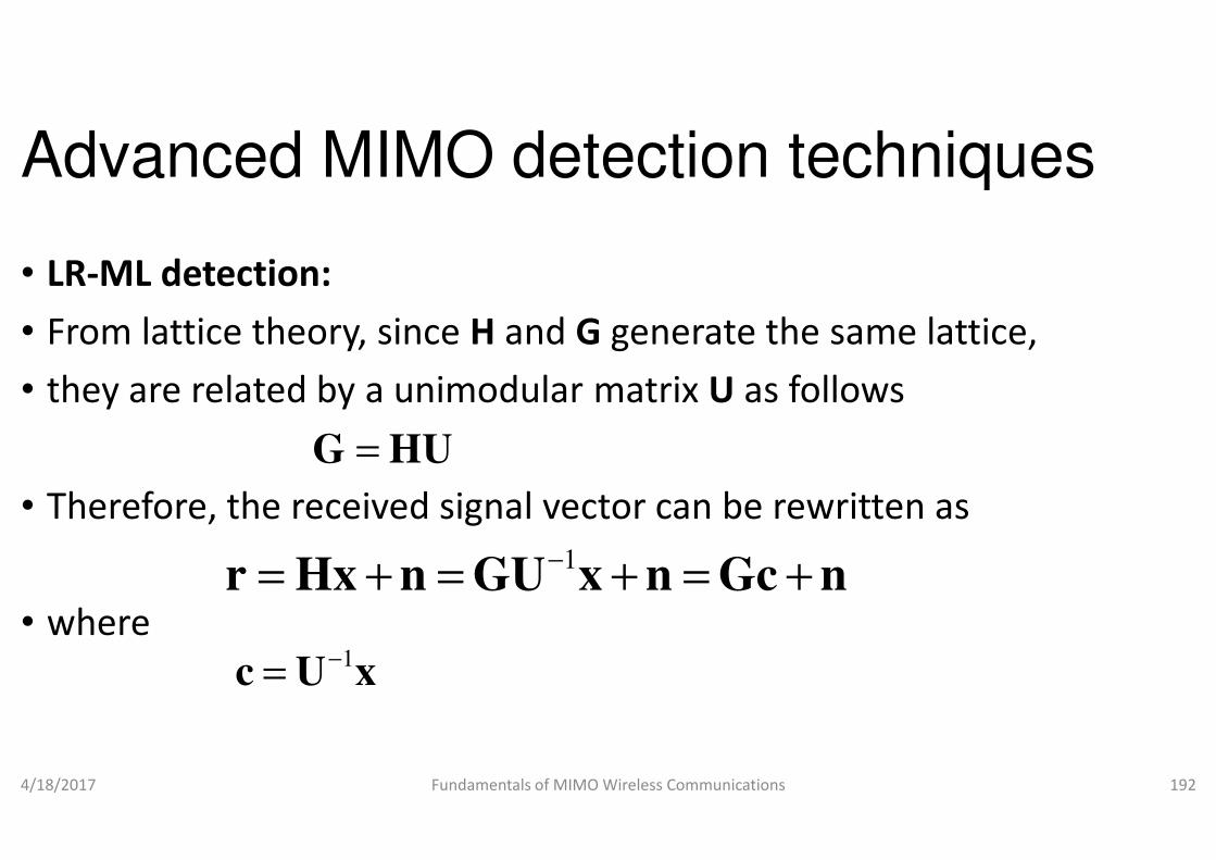
Advanced MIMO detection techniques
• LR-ML detection:
• From lattice theory, since H and G
• they are related by a unimodular matrix
=G HU
• Therefore, the received signal vector can be rewritten as
• where
4/18/2017 Fundamentals of MIMO Wireless Communications
=G HU
1−= + = + = +r Hx n GU x n Gc n
1−=c U x
Advanced MIMO detection techniques
generate the same lattice,
matrix U as follows
Therefore, the received signal vector can be rewritten as
Fundamentals of MIMO Wireless Communications 192
= + = + = +r Hx n GU x n Gc n
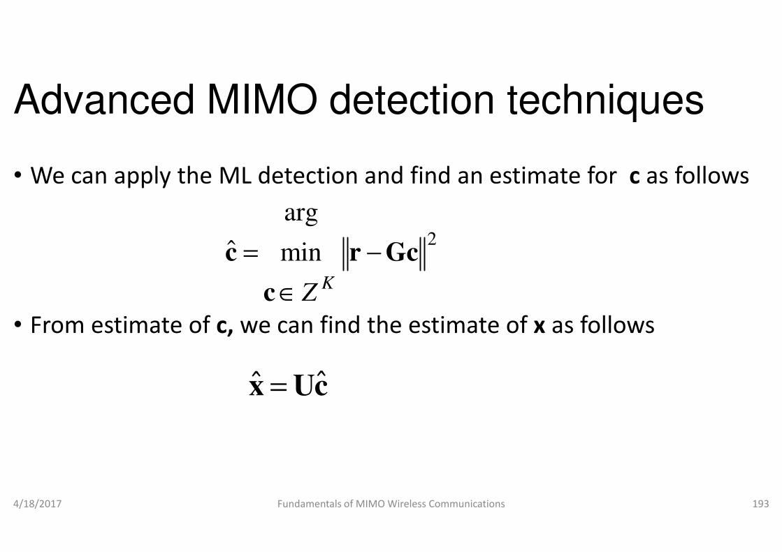
Advanced MIMO detection techniques
• We can apply the ML detection and find an estimate for
min
arg
ˆ Gcrc −
∈
=K
• From estimate of c, we can find the estimate of
4/18/2017 Fundamentals of MIMO Wireless Communications
c∈ KZ
ˆˆ =x Uc
Advanced MIMO detection techniques
We can apply the ML detection and find an estimate for c as follows
2Gc
we can find the estimate of x as follows
Fundamentals of MIMO Wireless Communications 193

Advanced MIMO detection techniques
• LR-ZF detection:
• Similarly, we can apply the ZF over the new matrix
• which is more well behaved and
• will minimize the noise enhancement• will minimize the noise enhancement
• Note that G+ is the Moore-Penrose inverse of
4/18/2017 Fundamentals of MIMO Wireless Communications
( ) ( 1+ + + − + += + = + = + = +G r G Hx n G GU x n G Gc n c G n
Advanced MIMO detection techniques
Similarly, we can apply the ZF over the new matrix G instead of H
which is more well behaved and
will minimize the noise enhancementwill minimize the noise enhancement
Penrose inverse of G
Fundamentals of MIMO Wireless Communications 194
) ( )1+ + + − + += + = + = + = +G r G Hx n G GU x n G Gc n c G n
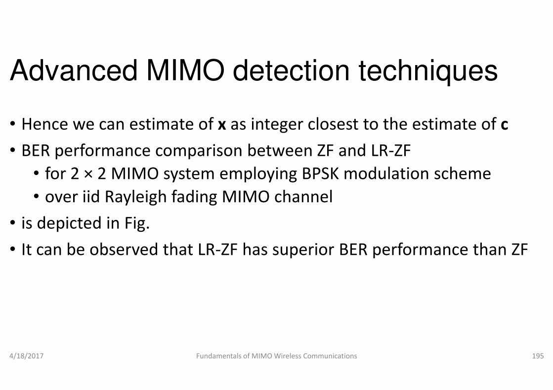
Advanced MIMO detection techniques
• Hence we can estimate of x as integer closest to the estimate of
• BER performance comparison between ZF and LR
• for 2 × 2 MIMO system employing BPSK modulation scheme
• over iid Rayleigh fading MIMO channel • over iid Rayleigh fading MIMO channel
• is depicted in Fig.
• It can be observed that LR-ZF has superior BER performance than ZF
4/18/2017 Fundamentals of MIMO Wireless Communications
Advanced MIMO detection techniques
integer closest to the estimate of c
BER performance comparison between ZF and LR-ZF
2 MIMO system employing BPSK modulation scheme
Rayleigh fading MIMO channel Rayleigh fading MIMO channel
ZF has superior BER performance than ZF
Fundamentals of MIMO Wireless Communications 195

• BER performance comparison between ZF and LR-ZF for 2 × 2 MIMO system employing BPSK employing BPSK modulation over iidRayeighfading MIMO channel
4/18/2017 Fundamentals of MIMO Wireless CommunicationsFundamentals of MIMO Wireless Communications 196

Advanced MIMO detection techniques
• LR-ZF-SIC detection:
• For SIC detection, do QR decomposition of
• Then multiply by to the received signal vectorHQ
( )
• where
• We can proceed with the same SIC detection techniques
• with this new equivalent system
4/18/2017 Fundamentals of MIMO Wireless Communications
( )1H H H H−= + = + = +Q r Q GU x n Q QRc n Rc Q n
1−=c U x
Advanced MIMO detection techniques
For SIC detection, do QR decomposition of
Then multiply by to the received signal vector
=G QR
( )
We can proceed with the same SIC detection techniques
with this new equivalent system
Fundamentals of MIMO Wireless Communications 197
( )H H H H= + = + = +Q r Q GU x n Q QRc n Rc Q n
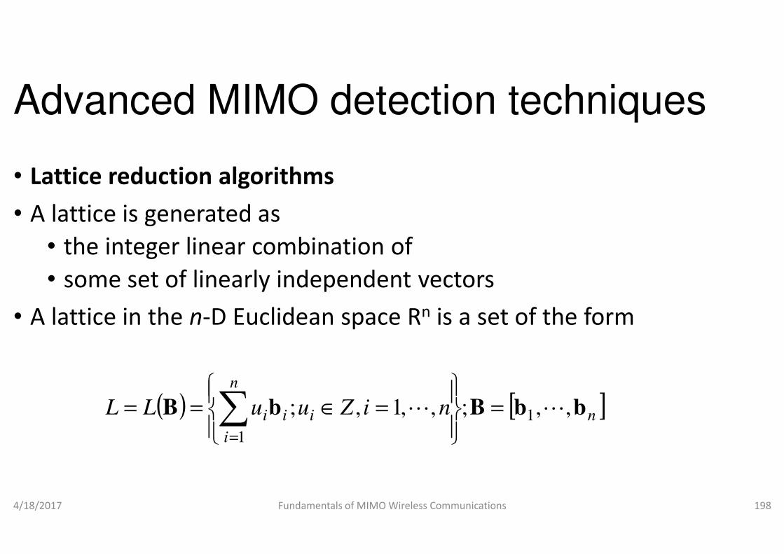
Advanced MIMO detection techniques
• Lattice reduction algorithms
• A lattice is generated as
• the integer linear combination of
• some set of linearly independent vectors• some set of linearly independent vectors
• A lattice in the n-D Euclidean space
4/18/2017 Fundamentals of MIMO Wireless Communications
( ) i
n
i
ii iZuuLL bB 1,;
1
=∈== ∑=
Advanced MIMO detection techniques
the integer linear combination of
some set of linearly independent vectorssome set of linearly independent vectors
D Euclidean space Rn is a set of the form
Fundamentals of MIMO Wireless Communications 198
[ ]nn bbB ,,;,,1 1 LL =

Advanced MIMO detection techniques
• A lattice L can be generated by different bases for n≥2 and
• hence there is no unique basis
• We can obtain an equivalent basis from another basis
• by multiplying an integer unimodular• by multiplying an integer unimodular
• Basically this is the result of three operations
• (a) exchanging two columns
• (b) multiplying any column by -1 and
• (c) adding an integer multiple of one column to another
4/18/2017 Fundamentals of MIMO Wireless Communications
Advanced MIMO detection techniques
can be generated by different bases for n≥2 and
basis from another basis
unimodular matrixunimodular matrix
Basically this is the result of three operations (illustrated in Fig.):
1 and
(c) adding an integer multiple of one column to another
Fundamentals of MIMO Wireless Communications 199

Fig. (a) basis vectors b1
and b2 for the integer lattice Z2 (b) exchanging two columns b1
and b2 (c) and b2 (c) multiplying both columns by -1 (d) adding twice of column b1 to column b2
4/18/2017 Fundamentals of MIMO Wireless CommunicationsFundamentals of MIMO Wireless Communications 200

Advanced MIMO detection techniques
• Lattice reduction algorithms are developed for real valued lattices
• for complex MIMO system
• Use equivalent real channel model as follows
= +y Hx n
• Use equivalent real channel model as follows
• Now the dimension will be doubled (say and )
4/18/2017 Fundamentals of MIMO Wireless Communications
( )( )
( )( )
=
H
H
y
y
Im
Re
Im
Re
Advanced MIMO detection techniques
Lattice reduction algorithms are developed for real valued lattices
Use equivalent real channel model as followsUse equivalent real channel model as follows
Now the dimension will be doubled (say and )
Fundamentals of MIMO Wireless Communications 201
( )( )
( )( )
( )( )
+
−
n
n
x
x
H
H
Im
Re
Im
Re
Re
Im
2T
m N= 2R
n N=
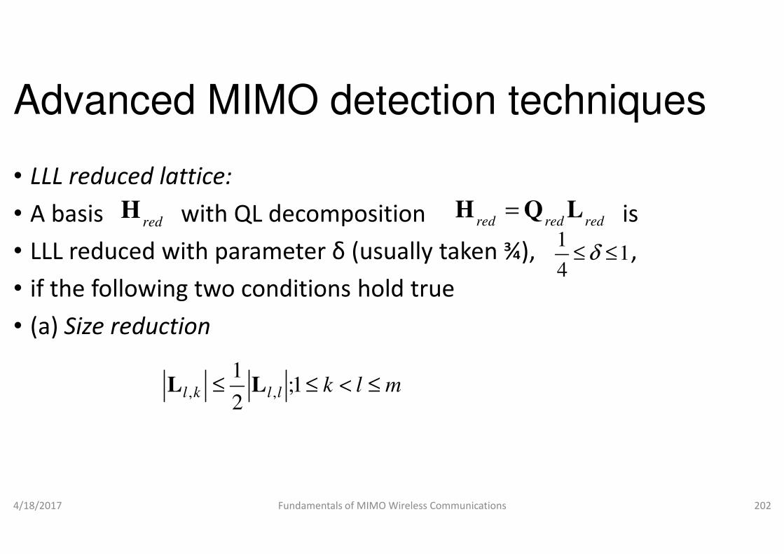
Advanced MIMO detection techniques
• LLL reduced lattice:
• A basis with QL decomposition is
• LLL reduced with parameter δ (usually taken ¾), ,
• if the following two conditions hold true
redH
• if the following two conditions hold true
• (a) Size reduction
4/18/2017 Fundamentals of MIMO Wireless Communications
mlkllkl ≤<≤≤ 1;2
1,, LL
Advanced MIMO detection techniques
A basis with QL decomposition is
LLL reduced with parameter δ (usually taken ¾), ,
if the following two conditions hold true
red red red=H Q L
11
4δ≤ ≤
if the following two conditions hold true
Fundamentals of MIMO Wireless Communications 202
4
m
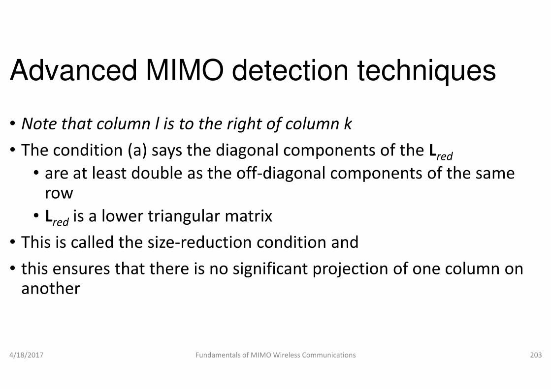
Advanced MIMO detection techniques
• Note that column l is to the right of column k
• The condition (a) says the diagonal components of the
• are at least double as the off-diagonal components of the same rowrow
• Lred is a lower triangular matrix
• This is called the size-reduction condition and
• this ensures that there is no significant projection of one column on another
4/18/2017 Fundamentals of MIMO Wireless Communications
Advanced MIMO detection techniques
Note that column l is to the right of column k
The condition (a) says the diagonal components of the Lred
diagonal components of the same
reduction condition and
this ensures that there is no significant projection of one column on
Fundamentals of MIMO Wireless Communications 203
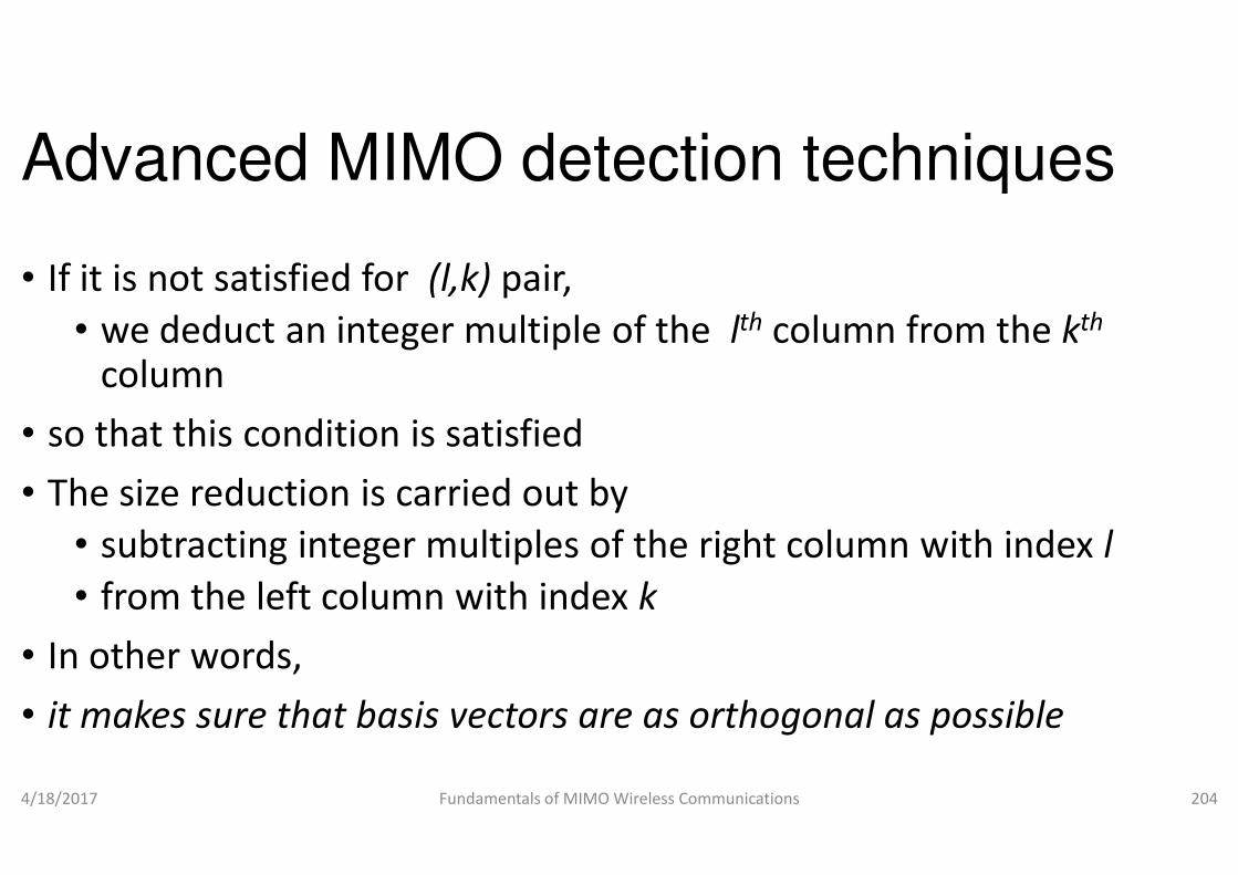
Advanced MIMO detection techniques
• If it is not satisfied for (l,k) pair,
• we deduct an integer multiple of the column
• so that this condition is satisfied• so that this condition is satisfied
• The size reduction is carried out by
• subtracting integer multiples of the right column with index
• from the left column with index
• In other words,
• it makes sure that basis vectors are as orthogonal as possible
4/18/2017 Fundamentals of MIMO Wireless Communications
Advanced MIMO detection techniques
we deduct an integer multiple of the lth column from the kth
The size reduction is carried out by
subtracting integer multiples of the right column with index l
from the left column with index k
it makes sure that basis vectors are as orthogonal as possible
Fundamentals of MIMO Wireless Communications 204

Advanced MIMO detection techniques
• This condition does not guarantee a minimal basis,
• there is another condition called as
• which will ensure the correct sorting of the columns
• Swapping of columns improve the basis• Swapping of columns improve the basis
• The last column of the reduced lattice can be thought of as the shortest vector
• (b) Sorting
4/18/2017 Fundamentals of MIMO Wireless Communications
[ ] [ ],1,122
≤++ kkkk redred LLδ
Advanced MIMO detection techniques
This condition does not guarantee a minimal basis,
there is another condition called as Lovasz condition
which will ensure the correct sorting of the columns
Swapping of columns improve the basisSwapping of columns improve the basis
The last column of the reduced lattice can be thought of as the
Fundamentals of MIMO Wireless Communications 205
[ ] 11;,122
−≤≤++ mkkkredL

Advanced MIMO detection techniques
• The condition (b) ensures proper sorting
• since the lengths of the columns are only compared
• on the basis of a little 2×2 submatrix
• If the above condition is not satisfied, • If the above condition is not satisfied,
• we will interchange the columns
• Why are we considering 2×2 submatrices
• This will reduce the computational complexity
• at the price of lower performance especially for big channel matrices
4/18/2017 Fundamentals of MIMO Wireless Communications
Advanced MIMO detection techniques
The condition (b) ensures proper sorting
since the lengths of the columns are only compared
submatrix
If the above condition is not satisfied, If the above condition is not satisfied,
we will interchange the columns
submatrices?
This will reduce the computational complexity
at the price of lower performance especially for big channel
Fundamentals of MIMO Wireless Communications 206

Advanced MIMO detection techniques
• The columns have to be ordered according to their lengths,
• shortest columns right
• and largest on the left
• Example • Example
• Explain the above condition (b) with the help of an example
• Solution:
4/18/2017 Fundamentals of MIMO Wireless Communications
Advanced MIMO detection techniques
The columns have to be ordered according to their lengths,
Explain the above condition (b) with the help of an example
Fundamentals of MIMO Wireless Communications 207
;
0
00
000
0000
5554535251
44434241
333231
2221
11
=
LLLLL
LLLL
LLL
LL
L
L
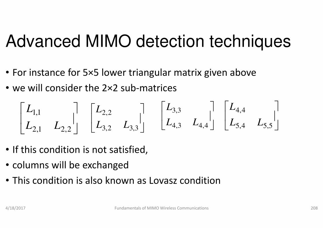
Advanced MIMO detection techniques
• For instance for 5×5 lower triangular matrix given above
• we will consider the 2×2 sub-matrices
1,1L
2,2L
• If this condition is not satisfied,
• columns will be exchanged
• This condition is also known as Lovasz
4/18/2017 Fundamentals of MIMO Wireless Communications
2,21,2
1,1
LL
L
3,32,3
2,2
LL
L
Advanced MIMO detection techniques
5 lower triangular matrix given above
matrices
3,3L
4,4L
Lovasz condition
Fundamentals of MIMO Wireless Communications 208
4,43,4
3,3
LL
5,54,5 LL
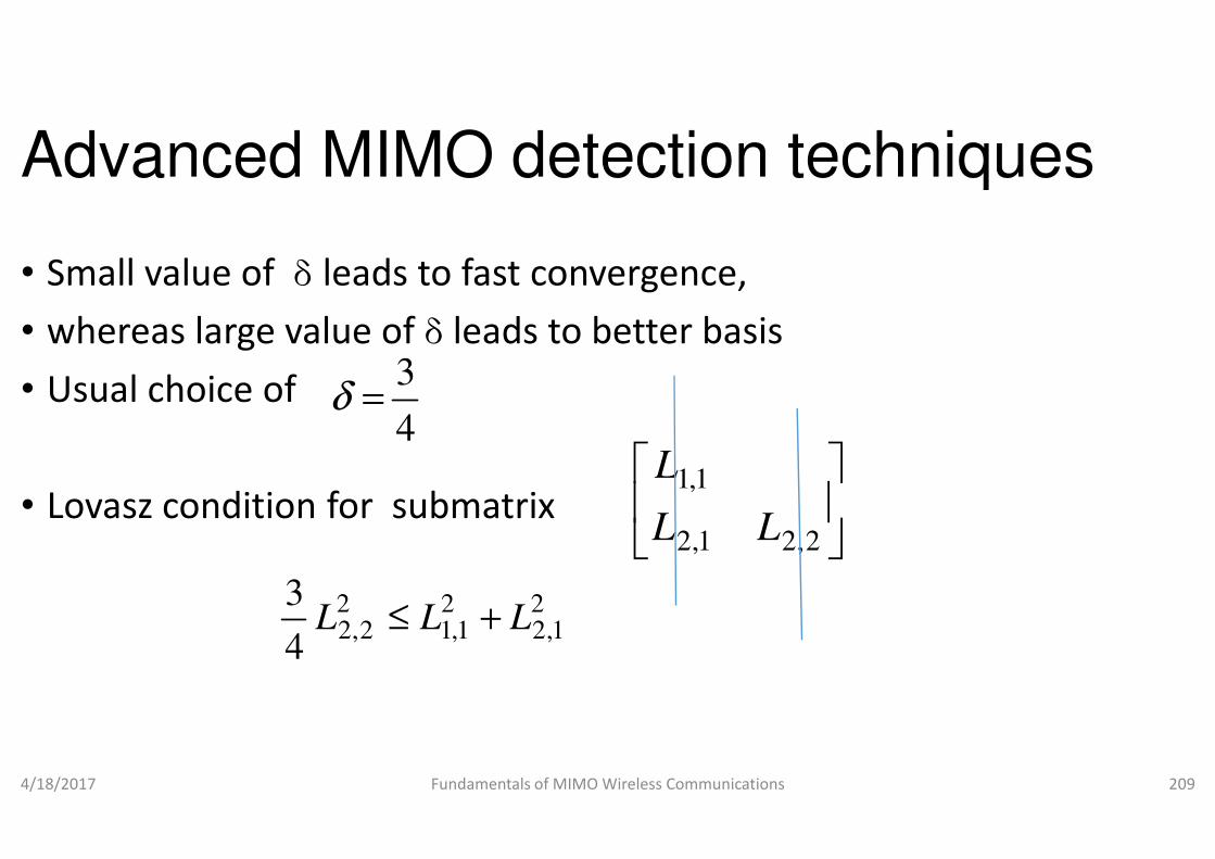
Advanced MIMO detection techniques
• Small value of δ leads to fast convergence,
• whereas large value of δ leads to better basis
• Usual choice of 3
4δ =
• Lovasz condition for submatrix
4/18/2017 Fundamentals of MIMO Wireless Communications
4
21,2
21,1
22,2
4
3LLL +≤
Advanced MIMO detection techniques
leads to fast convergence,
leads to better basis
Fundamentals of MIMO Wireless Communications 209
2,21,2
1,1
LL
L
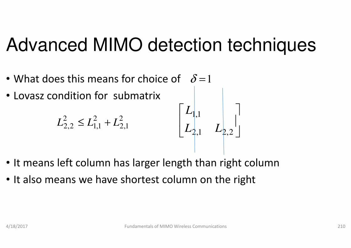
Advanced MIMO detection techniques
• What does this means for choice of
• Lovasz condition for submatrix
21,2
21,1
22,2
3LLL +≤
• It means left column has larger length than right column
• It also means we have shortest column on the right
4/18/2017 Fundamentals of MIMO Wireless Communications
1,21,12,24
LLL +≤
Advanced MIMO detection techniques
choice of 1δ =
1,1
LL
L
It means left column has larger length than right column
It also means we have shortest column on the right
Fundamentals of MIMO Wireless Communications 210
2,21,2 LL
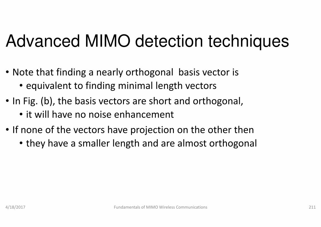
Advanced MIMO detection techniques
• Note that finding a nearly orthogonal basis vector is
• equivalent to finding minimal length vectors
• In Fig. (b), the basis vectors are short and orthogonal,
• it will have no noise enhancement• it will have no noise enhancement
• If none of the vectors have projection on the other then
• they have a smaller length and are almost orthogonal
4/18/2017 Fundamentals of MIMO Wireless Communications
Advanced MIMO detection techniques
Note that finding a nearly orthogonal basis vector is
equivalent to finding minimal length vectors
In Fig. (b), the basis vectors are short and orthogonal,
it will have no noise enhancementit will have no noise enhancement
If none of the vectors have projection on the other then
they have a smaller length and are almost orthogonal
Fundamentals of MIMO Wireless Communications 211
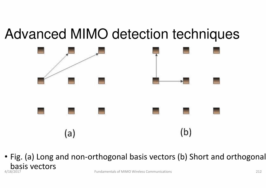
Advanced MIMO detection techniques
• Fig. (a) Long and non-orthogonal babasis vectors
4/18/2017 Fundamentals of MIMO Wireless Communications
Advanced MIMO detection techniques
l basis vectors (b) Short and orthogonal
Fundamentals of MIMO Wireless Communications 212
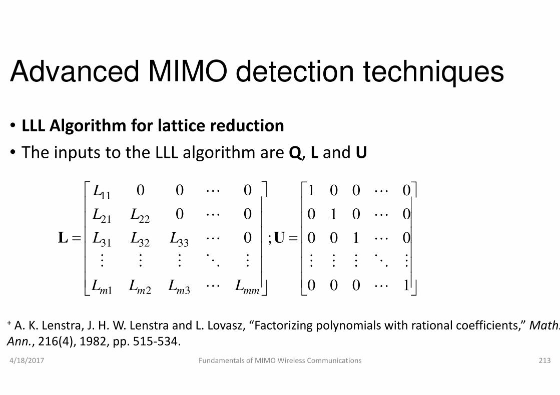
Advanced MIMO detection techniques
• LLL Algorithm for lattice reduction
• The inputs to the LLL algorithm are
00011 LL
4/18/2017 Fundamentals of MIMO Wireless Communications
= ;0
00
000
321
333231
2221
11
L
MOMMM
L
L
L
UL
mmmmm LLLL
LLL
LL
L
+ A. K. Lenstra, J. H. W. Lenstra and L. Lovasz, “Factorizing polynomials with rational coefficients,”
Ann., 216(4), 1982, pp. 515-534.
Advanced MIMO detection techniques
LLL Algorithm for lattice reduction
The inputs to the LLL algorithm are Q, L and U
0001 L
Fundamentals of MIMO Wireless Communications 213
=
1000
0100
0010
0001
L
MOMMM
L
L
L
U
, “Factorizing polynomials with rational coefficients,” Math.

Advanced MIMO detection techniques
• The outputs are reduced matrices viz.
• LLL LR algorithm
• Initialization:
, ,red red m
= = =Q Q L L U I
• (%initial inputs, U is a unimodular matrix)
• (% k is the column under consideration and start from the last but second column, note that m=2NT)
4/18/2017 Fundamentals of MIMO Wireless Communications
, ,red red m
= = =Q Q L L U I
1k m= −
Advanced MIMO detection techniques
reduced matrices viz. Qred, Lred and Ured
matrix)
(% k is the column under consideration and start from the last but
Fundamentals of MIMO Wireless Communications 214
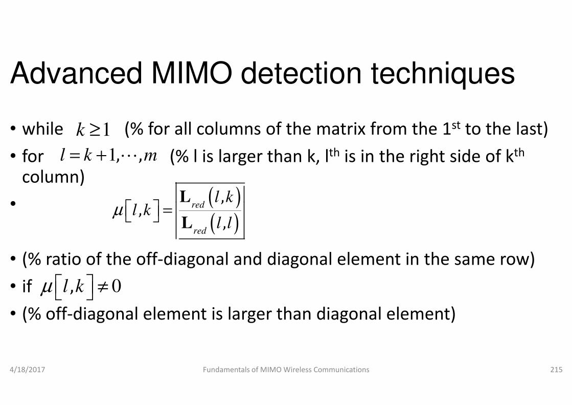
Advanced MIMO detection techniques
• while (% for all columns of the matrix from the 1
• for (% l is larger than k, column)
•
1k ≥
1, ,l k m= + L
( ),,
,
redl k
l kµ =L•
• (% ratio of the off-diagonal and diagonal element in the same row)
• if
• (% off-diagonal element is larger than diagonal element)
4/18/2017 Fundamentals of MIMO Wireless Communications
( )( ),
,,
red
red
l kl k
l lµ =
L
L
0,l kµ ≠
Advanced MIMO detection techniques
while (% for all columns of the matrix from the 1st to the last)
for (% l is larger than k, lth is in the right side of kth
diagonal and diagonal element in the same row)
diagonal element is larger than diagonal element)
Fundamentals of MIMO Wireless Communications 215
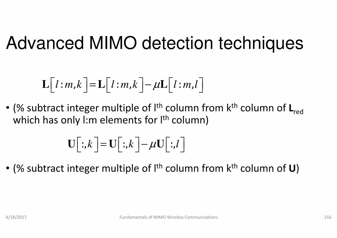
Advanced MIMO detection techniques
• (% subtract integer multiple of lth column from which has only l:m elements for lth
: , : , : ,l m k l m k l m lµ = − L L L
which has only l:m elements for lth
• (% subtract integer multiple of lth column from
4/18/2017 Fundamentals of MIMO Wireless Communications
:, :, :,k k lµ = − U U U
Advanced MIMO detection techniques
column from kth column of Lredth column)
: , : , : ,l m k l m k l m l L L L
th column)
column from kth column of U)
Fundamentals of MIMO Wireless Communications 216
:, :, :,k k l U U U

Advanced MIMO detection techniques
• end
• if
• Exchange columns k and k+1 in L
[ ] [21,1 kkk redred ≥++ LLδ
• Exchange columns k and k+1 in Lred
• (% when we interchange k and k+1 column, now the new matrix will no longer be lower triangular, we need to force zero the element zero)
4/18/2017 Fundamentals of MIMO Wireless Communications
Advanced MIMO detection techniques
and U
] [ ] 22,1, kkkk red ++ L
red and U
% when we interchange k and k+1 column, now the new matrix will no longer be lower triangular, we need to force zero the L(k,k+1)
Fundamentals of MIMO Wireless Communications 217

Advanced MIMO detection techniques
[[ :
1;
+
+=
−=
kk
k
red
red
L
LΘ α
αβ
βα
• (%Calculate Givens rotation matrix such that elementbecome zero)
4/18/2017 Fundamentals of MIMO Wireless Communications
[ ]1:1,1: =++ kkkred ΘLL
[ ] [redred kk QQ :,1::, =+
Advanced MIMO detection techniques
]]
[ ][ ]1,1:
1,
1,1
1,1
++
+=
++
+
kkk
kk
k
k
red
red
L
Lβ
(%Calculate Givens rotation matrix such that element L(k,k+1)
Fundamentals of MIMO Wireless Communications 218
[ ]1:1,1: ++ kkkredΘL
Θ
] Tkk Θ1: +

Advanced MIMO detection techniques
• (% consider all columns, but only the k and k+1 rows only, Givens
• rotation operate on columns only)
{ }1 1min ,k k m= + −
• else
• k=k-1
• end
• end
4/18/2017 Fundamentals of MIMO Wireless Communications
{ }1 1min ,k k m= + −
Advanced MIMO detection techniques
(% consider all columns, but only the k and k+1 rows only, Givens
Fundamentals of MIMO Wireless Communications 219
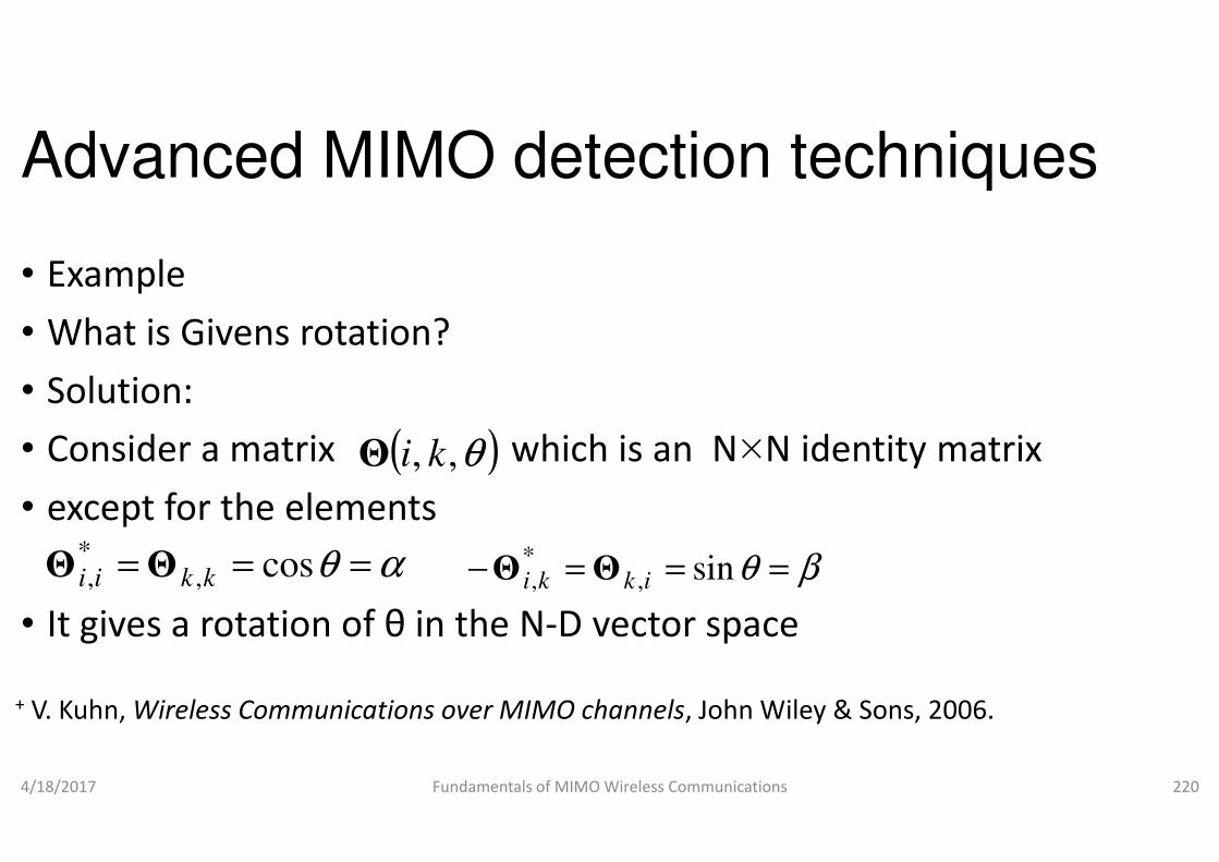
Advanced MIMO detection techniques
• Example
• What is Givens rotation?
• Solution:
• Consider a matrix which is an N( )θ,, kiΘ• Consider a matrix which is an N
• except for the elements
• It gives a rotation of θ in the N-D vector space
4/18/2017 Fundamentals of MIMO Wireless Communications
( )θ,, kiΘ
αθ === cos,*, kkii ΘΘ =− *
,ki ΘΘ
+ V. Kuhn, Wireless Communications over MIMO channels
Advanced MIMO detection techniques
Consider a matrix which is an N×N identity matrix Consider a matrix which is an N×N identity matrix
D vector space
Fundamentals of MIMO Wireless Communications 220
βθ == sin,ikΘ
Wireless Communications over MIMO channels, John Wiley & Sons, 2006.
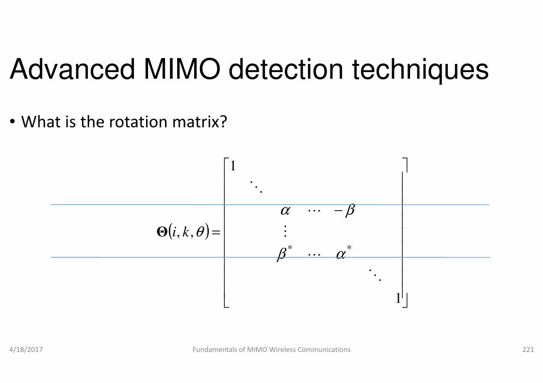
Advanced MIMO detection techniques
• What is the rotation matrix?
1
O
4/18/2017 Fundamentals of MIMO Wireless Communications
( )
=,,
O
θkiΘ
Advanced MIMO detection techniques
Fundamentals of MIMO Wireless Communications 221
−
1
**
O
L
M
L
αβ
βα

Advanced MIMO detection techniques
• Define
( )
0 0 0 0
0 0 0
0 0 0 0
cos sin
, ,sin cos
i k
θ θ
θ
Θ =
I
4/18/2017 Fundamentals of MIMO Wireless Communications
( )0 0 0 0
0 0 0
0 0 0 0
cos sin
, ,sin cos
i k θ θ θ Θ =
Advanced MIMO detection techniques
0 0 0 0
0 0 0
0 0 0 0
cos sin
sin cos
θ θ
−
I
Fundamentals of MIMO Wireless Communications 222
0 0 0 0
0 0 0
0 0 0 0
cos sin
sin cosθ θ
I
I

Advanced MIMO detection techniques
• where i is the row that contains
• and k is the row that contains
θα cos= θβ sin−=−
θβ sin= θα cos=
• If θ is chosen properly
• it can force the ith element of a colubelow
• It also force the kth element as
4/18/2017 Fundamentals of MIMO Wireless Communications
θβ sin= θα cos=
x
Advanced MIMO detection techniques
column vector equal to zero as shown
Fundamentals of MIMO Wireless Communications 223
22ki xx +

Advanced MIMO detection techniques
• Assume xi and xk are the ith and kth
then
22cos k
xx
x
+
== θα
4/18/2017 Fundamentals of MIMO Wireless Communications
22
ki xx +
22sin
ki
i
xx
x
+
== θβ ( ,, kiΘ
Advanced MIMO detection techniques
element of the column vector,
1
O
Fundamentals of MIMO Wireless Communications 224
)
−
=
1
,**
O
L
M
L
O
αβ
βα
θ
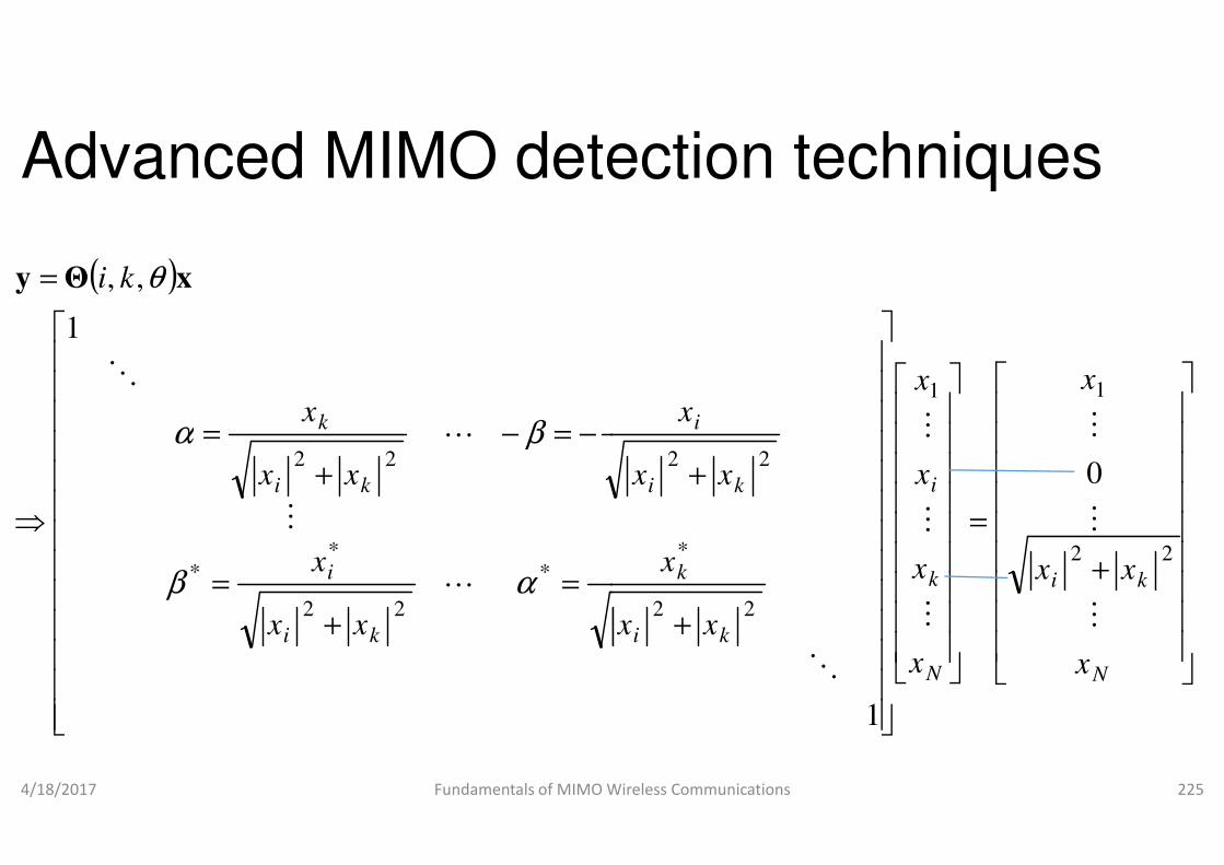
Advanced MIMO detection techniques
( )
−=−=
=
kx
ki
L
O
1
,,
βα
θ xΘy
4/18/2017 Fundamentals of MIMO Wireless Communications
=
+
=
−=−
+
=
⇒
ki
i
ki
k
xx
x
xx
L
M
L
*
22
**
22
αβ
βα
Advanced MIMO detection techniques
i
xxx
MM
11
Fundamentals of MIMO Wireless Communications 225
+
=
+
+
N
ki
N
k
i
ki
k
ki
i
x
xx
x
x
x
xx
x
xx
M
M
M
M
M
M
O
22
22
*
220
1

Advanced MIMO detection techniques
• Example
• Explain LLL algorithm to find for a simple matrix, ,red red red
Q R U
=21
H
• Solution:
• We can find the condition number of cond(H)=14.9330
4/18/2017 Fundamentals of MIMO Wireless Communications
=
43H
Advanced MIMO detection techniques
Explain LLL algorithm to find for a simple matrix, ,red red red
Q R U
We can find the condition number of H by using MATLAB command
Fundamentals of MIMO Wireless Communications 226

Advanced MIMO detection techniques
• Condition number of H should be closer to 1
• Apply LLL algorithm, the inputs are:
• The input to the LLL algorithm above is
• In MATLAB, one can find • In MATLAB, one can find
• [Q R]=qr(fliplr(H)); % flip columns
• L=fliplr(flipud(R)); % flip rows and then flip columns
• Q=fliplr(Q); % flip columns
4/18/2017 Fundamentals of MIMO Wireless Communications
Advanced MIMO detection techniques
should be closer to 1
Apply LLL algorithm, the inputs are:
The input to the LLL algorithm above is Q, L and U=I
(R)); % flip rows and then flip columns
Fundamentals of MIMO Wireless Communications 227
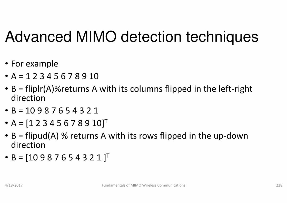
Advanced MIMO detection techniques
• For example
• A = 1 2 3 4 5 6 7 8 9 10
• B = fliplr(A)%returns A with its columns flipped in the leftdirectiondirection
• B = 10 9 8 7 6 5 4 3 2 1
• A = [1 2 3 4 5 6 7 8 9 10]T
• B = flipud(A) % returns A with its rows flipped in the updirection
• B = [10 9 8 7 6 5 4 3 2 1 ]T
4/18/2017 Fundamentals of MIMO Wireless Communications
Advanced MIMO detection techniques
with its columns flipped in the left-right
with its rows flipped in the up-down
Fundamentals of MIMO Wireless Communications 228
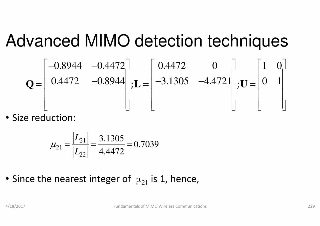
Advanced MIMO detection techniques
• Size reduction:
0 8944 0 4472 0 4472 0 1 0
0 4472 0 8944 3 1305 4 4721 0 1
. . .
. . . .; ;
− −
− − −= = =
Q L U
• Size reduction:
• Since the nearest integer of µ21 is 1, hence,
4/18/2017 Fundamentals of MIMO Wireless Communications
7039.04472.4
1305.3
22
2121 ===
L
Lµ
Advanced MIMO detection techniques
0 8944 0 4472 0 4472 0 1 0
0 4472 0 8944 3 1305 4 4721 0 1
. . .
. . . .; ;
− − −= = =
Q L U
is 1, hence,
Fundamentals of MIMO Wireless Communications 229
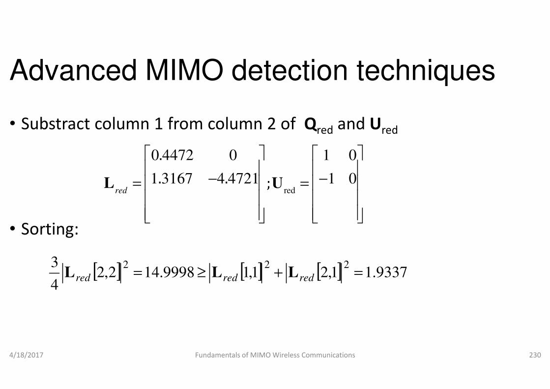
Advanced MIMO detection techniques
• Substract column 1 from column 2 of
0 4472 0 1 0
1 3167 4 4721 1 0
.
. . ;red
− −= =
L U
• Sorting:
4/18/2017 Fundamentals of MIMO Wireless Communications
.
. . ;red
[ ] [ ]1,19998.142,24
3 22+≥= redred LL
Advanced MIMO detection techniques
column 1 from column 2 of Qred and Ured
red
0 4472 0 1 0
1 3167 4 4721 1 0;
− −= =
L U
Fundamentals of MIMO Wireless Communications 230
red;
[ ] 9337.11,22
=+ redL
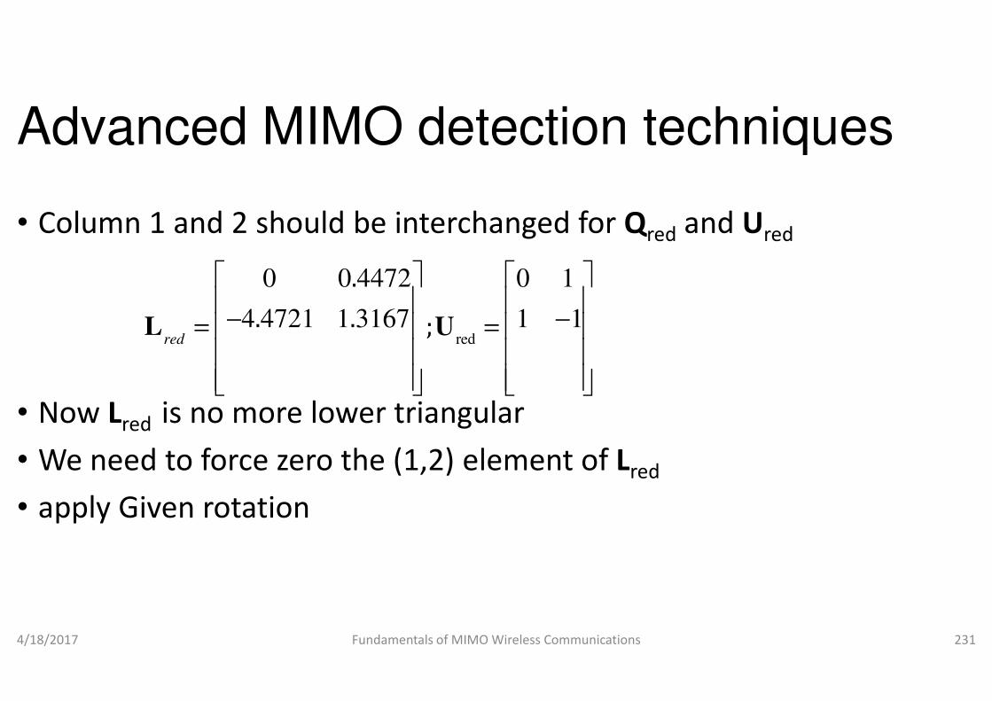
Advanced MIMO detection techniques
• Column 1 and 2 should be interchanged for
red
0 0 4472 0 1
4 4721 1 3167 1 1
.
. . ;red
− −= =
L U
• Now Lred is no more lower triangular
• We need to force zero the (1,2) element of
• apply Given rotation
4/18/2017 Fundamentals of MIMO Wireless Communications
.
. . ;
Advanced MIMO detection techniques
Column 1 and 2 should be interchanged for Qred and Ured
0 0 4472 0 1
4 4721 1 3167 1 1
− −= =
is no more lower triangular
We need to force zero the (1,2) element of Lred
Fundamentals of MIMO Wireless Communications 231
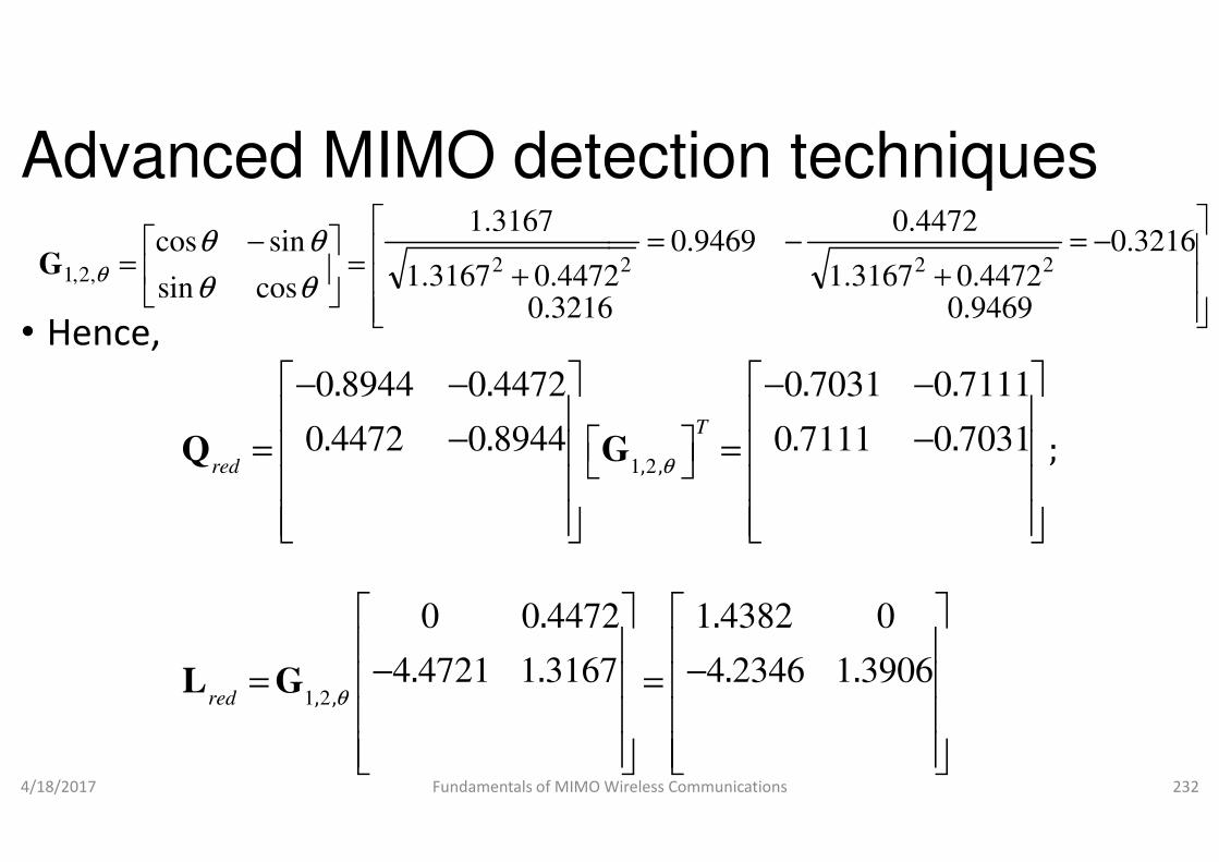
Advanced MIMO detection techniques
• Hence,
+=
−=
3216.04472.03167.1
3167.1
cossin
sincos2,2,1
θθ
θθθG
0 8944 0 4472 0 7031 0 7111
0 4472 0 8944 0 7111 0 7031
. . . .
. . . .
− − − −
− − = = Q G
4/18/2017 Fundamentals of MIMO Wireless Communications
1 2
0 4472 0 8944 0 7111 0 7031
0 0 4472 1 4382 0
4 4721 1 3167 4 2346 1 3906, ,
. . . .
. . . .
. .
. . . .
red
red θ
− − = =
− −= =
Q G
L G
Advanced MIMO detection techniques
−=
+−=
9469.03216
3216.04472.03167.1
4472.09469.0
4472 222
0 8944 0 4472 0 7031 0 7111
0 4472 0 8944 0 7111 0 7031, ,
. . . .
. . . . ;T
− − − −
− − = = Q G
Fundamentals of MIMO Wireless Communications 232
1 20 4472 0 8944 0 7111 0 7031
0 0 4472 1 4382 0
4 4721 1 3167 4 2346 1 3906
, ,
. . . .
. . . . ;
. .
. . . .
T
θ
− − = =
− −= =
Q G

Advanced MIMO detection techniques
• Therefore,2 0 9888 2 1
4 0 9777 4 1
.
.red red red red
− −
− −= = = =
H Q L HU
• Now the cond(Hred)=10.8753
• It is closer to 1
4/18/2017 Fundamentals of MIMO Wireless Communications
.
Advanced MIMO detection techniques
2 0 9888 2 1
4 0 9777 4 1red red red red
− −
− −= = = =
H Q L HU
Fundamentals of MIMO Wireless Communications 233