Embed Size (px)
Citation preview

Yaesu FT301D Digital Display Replacement Project May 12, 2011 (updated Aug. 12, 2013)
WA7ZVY Page 1 of 9
A Replacement Display for the Yaesu FT301D HF Transceiver
by
WA7ZVY
In the summer of 1977 I purchased my first HF transceiver. It was a great radio with
excellent specifications and capabilities, at least for those days. It came with a,
somewhat new at the time, digital frequency readout. After a few years, though, the
display developed some missing segments in the 6 digit 7-segment LED readouts.
Those displays, Texas Instruments TIL306 and TIL308, had not only the LEDs in them,
they also contained digital decade counters, latches and LED drivers. They ran hotter
than blazes!, and, they were located in a tiny space at the front of the radio that had
almost no cooling air movement. With all of that heat and no cooling, they didn’t last
long.
Initially, to fix those missing segments, I purchased some new TIL306 and TIL308
displays and just replaced them. All was fine again! Well, at least for a few more years,
and then, poof, a few more burned out segments. I lived with the few missing segments
for years… and slowly adapted to the “new hieroglyphic language” that it portrayed. I
could still determine what frequency I was operating on, as the still working segments
gave a unique signature, but anyone else had a pretty hard time deciphering it all. After
many years of putting up with all of that and then with the radio sitting idle on the shelf
for many years, I once again found myself staring at that display and thinking, it’s time
to really fix this thing! I figured that those displays had probably long ago gone “end of
life.” But, in the interest of not working too hard at fixing this old radio, I did a quick look
on the web to see if anyone had those displays in stock… as expected, nothing… long
gone obsolete! Next I did a quick search to see if anyone else had tackled this problem
and I did find a “sort of, maybe, kind of, sort of” fix that W5CEU had implemented
(http://www.aade.com/applications/FT301D.htm). He used an LCD digital counter module
to replace the display. While it provided the frequency readout, it certainly wasn’t a drop
in replacement and it didn’t have that same “red LED” look to it that would make the rig
look original. And, it also required some modifications to the front panel bezel window
along with picking up a new source for the LCD counter module’s input signal. His

Yaesu FT301D Digital Display Replacement Project May 12, 2011 (updated Aug. 12, 2013)
WA7ZVY Page 2 of 9
solution uses the radio’s RF Unit (PB-1433) mixer signal and the AF Unit (PB-1437)
BFO signals instead of the output of the radio’s “Counter Mixer Unit” (PB-1541). So, it
is definitely not a plug in replacement for the radio’s stock display unit. I really wanted
something that would exactly replace the original display and plug directly into the
radio’s existing connector with no modifications of the radio needed. It was time to
make “this project” a little more complicated!
I got out the old manual for the radio and studied the schematic of the display. On the
schematic it was listed as part number “PB-1542 Display Logic Unit.” But, after taking
apart the front panel of the radio and extracting the display board, I discovered that the
part number on mine was a newer version, PB-1542B, than what was shown in the
manual. That led me down the rabbit hole of checking the schematic against the actual
circuit board I had to find the differences. There were a few changes, but nothing too
serious.
The next task was a quick perusal of some various manufacturer datasheets to come up
with a reasonable way to build a new display. I decided to use a microcontroller to
pretty much do the entire function. A Microchip PIC16F887 part has plenty of I/O ports
to capture all of the incoming knob functions/settings, generate all of the output signals
to drive currently available simple 7-Segment LED displays, and even directly count the
frequency, as the PIC16F887 has a “gate” function for the Timer1/Counter1 input. So,
we were all set. The parts used would all be tiny surface mount (except for the
displays), to keep the physical size small and easy to build, well, at least with a good
magnifying glass! The prototype printed circuit board would be a bit of a challenge to do
in the home lab, as the PIC16F887 package I chose was the TQFP-44. This small
surface mount package (less than 0.5” on a side) wouldn’t take up too much room on
the circuit board, but it does have 0.8mm (0.031”) lead pitch. To make the prototype
PCB, I used the “direct etch method” using the Toner Transfer System tools and
consumables from Pulsar. (http://pulsarprofx.com) that are also available from Digi-Key
(www.digikey.com) All of the computer aided design tools used are freely available;
TinyCAD (http://tinycad.sourceforge.net) for schematic capture , FreePCB

Yaesu FT301D Digital Display Replacement Project May 12, 2011 (updated Aug. 12, 2013)
WA7ZVY Page 3 of 9
(http://www.freepcb.com) for the printed circuit board layout, and Microchip’s MPLAB
(www.microchip.com) for the firmware design written in MASM.
The resulting circuit design and firmware code duplicates all of the original functions of
the display, and even provides some corrected features in how the counter works and
what happens at the band edges when the counters roll-over or roll-under. Such as,
having the displayed MHz digit numbers go to 6 when tuning below 7.000.0 or go to 30
when tuning above 29.999.9 Likewise for all of the band edges that cause a roll-over or
roll-under condition of the count. The way the original radio’s counter/display works is
that it has a “Counter Mixer Unit” that preceeds the actual frequency counting function
of the “Display Logic Unit.” The “Counter Mix Unit” takes in the 5.0MHz to 5.5MHz VFO
frequency and mixes it with an 18.5MHz signal to come up with a 13.0 to 13.5MHz
signal that the display frequency counter counts. The counter only generates the
hundreds of KHz, tens of KHz, ones of KHz, and hundreds of Hz digits. The MHz digits
are generated by inputs from the front panel band switch. Somewhat of a complicated
way of doing all of this, but back in the 1970’s with those TIL306 and TIL308 integrated
displays, I suppose it made things easier to implement. In order to make the new
display a perfect drop in “form, fit, and function” replacement that perfectly plugs into the
existing radio internal connectors and needs no modifications of the radio’s circuitry, it
operates in a similar fashion. That means it also makes use of some of the “diode”
encoding that the high order MHz digits used to determine what number to display… it
is actually a bit more complicated in that it has to back track that “diode” encoding to
regenerate the MHz digits. Isn’t doing some things in firmware wonderful!, instead of
doing it all in hardware?!
Now for the details:
To remove the original display board:
Remove the radio’s top cover with the 4 plastic pull knobs.
Unplug the speaker connector and set aside the top cover.
Remove the 12 screws on the bottom cover and remove the bottom cover.

Yaesu FT301D Digital Display Replacement Project May 12, 2011 (updated Aug. 12, 2013)
WA7ZVY Page 4 of 9
Unplug the two square pin connectors on the bottom that are attached to the display board.
Remove the main frequency dial knob by loosening the two set screws in it.
Unsolder or cut the resistor that is attached to the display board and to the frequency calibrate control. You will need to re-attach this resistor when you install the new display circuit board.
Loosen the two bracket screws at the back side of the metal bracket that is attached to the display board.
Remove one screw located near/behind the frequency dial knob area.
Gently remove the Display Logic Unit PB-1542B
Pictures of the original Logic Display Unit when removed from the radio are shown
below:
Figure 1 : PB-1542B Display Logic Unit
Figure 2 : PB1542B Display Logic Unit

Yaesu FT301D Digital Display Replacement Project May 12, 2011 (updated Aug. 12, 2013)
WA7ZVY Page 5 of 9
The new display board is a two layer circuit board. Because I wanted to keep the etch
feature sizes relatively large to aid in etching the circuit board in the home lab, instead
of sending it out for initial fabrication, there are some wire jumpers added to the PCB. I
still haven’t come up with a really good way to fabricate more than two layer circuit
boards at home. But, at least with jumper wires on the top and bottom side, I can
“pretend” to have a four layer board! The jumpers on the top side are associated with
the LED displays (blue 30 gauge wire-wrap wire in photo below). Those jumpers provide
power to one set of the common anode pins on each display device. The jumpers on
the bottom side of the PCB connect the programming header for the Quickwriter PIC
Programmer (http://www.tech-tools.com) to the PIC16F887 device. These jumpers, and
the programming header, are not needed if you never intend to program or re-program
the microcontroller in-circuit. Figure 3 and Figure 4 (below) show the jumper wire
placement and also the top to bottom via wires needed for the home etched 2-layer
PCB that does not have plated through holes. To better show the jumper wiring
placement and via wires, the components have not yet been installed in the PCB.
Figure 3: New Display Logic Unit PCB (top)
Figure 4: New Display Logic Unit PCB (bottom)
Yaesu FT301D Digital Display Replacement Project May 12, 2011 (updated Aug. 12, 2013)
WA7ZVY Page 6 of 9
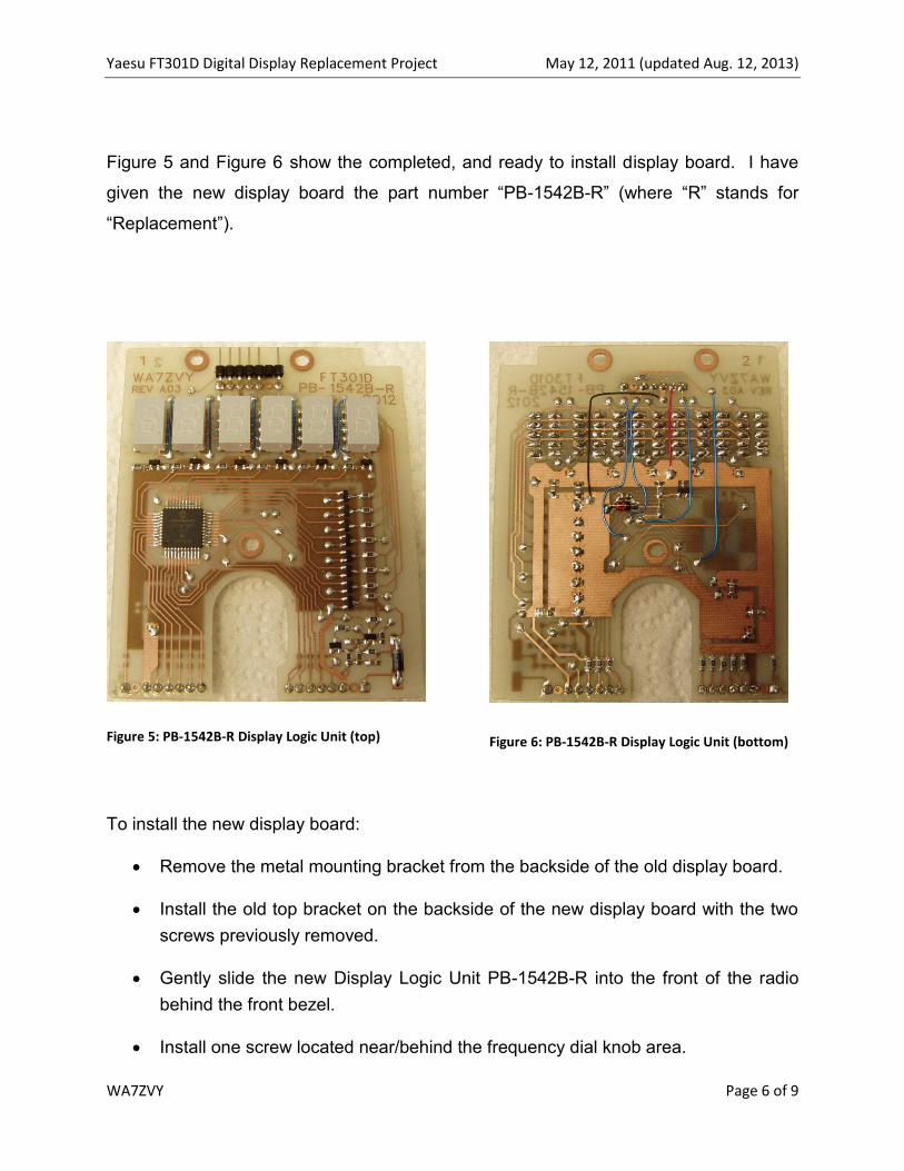
Figure 5 and Figure 6 show the completed, and ready to install display board. I have
given the new display board the part number “PB-1542B-R” (where “R” stands for
“Replacement”).
Figure 5: PB-1542B-R Display Logic Unit (top)
Figure 6: PB-1542B-R Display Logic Unit (bottom)
To install the new display board:
Remove the metal mounting bracket from the backside of the old display board.
Install the old top bracket on the backside of the new display board with the two
screws previously removed.
Gently slide the new Display Logic Unit PB-1542B-R into the front of the radio
behind the front bezel.
Install one screw located near/behind the frequency dial knob area.
Yaesu FT301D Digital Display Replacement Project May 12, 2011 (updated Aug. 12, 2013)
WA7ZVY Page 7 of 9
Install two screws through the mounting bracket at the top of the display board.
Re-attach the 3.3K ohm resistor coming from the front panel’s “Calibrate”
potentiometer. Solder it to the backside of the new display board at J1-1.
Push the two cabled square pin connectors onto the associated square pin
connectors on the new Display Logic Unit PB-1542B-R. The connectors are
keyed for proper alignment.
Install and tighten the main frequency dial knob.
Install the bottom cover and attach with 12 screws.
Plug in the speaker connector from the top cover.
Install the top cover and attach it by pushing down the 4 plastic buttons.
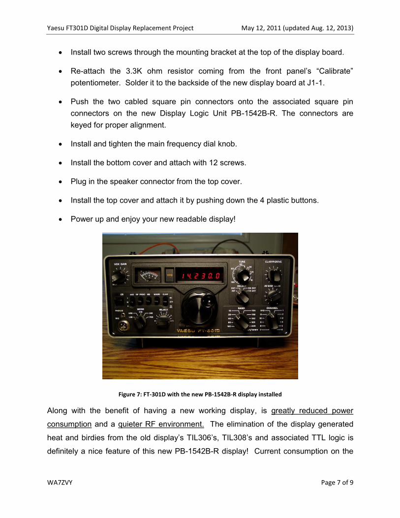
Power up and enjoy your new readable display!
Figure 7: FT-301D with the new PB-1542B-R display installed
Along with the benefit of having a new working display, is greatly reduced power
consumption and a quieter RF environment. The elimination of the display generated
heat and birdies from the old display’s TIL306’s, TIL308’s and associated TTL logic is
definitely a nice feature of this new PB-1542B-R display! Current consumption on the

Yaesu FT301D Digital Display Replacement Project May 12, 2011 (updated Aug. 12, 2013)
WA7ZVY Page 8 of 9
new display board is approximately 20mA. That is less than 1/50 of the current used by
the old original display board.
For those who want to do some further custom programming of the display features, the
programming header on the new display board allows a PIC programmer to be
connected and the firmware to be updated. The chassis of the FT-301D has a factory
cut out in the chassis frame that worked out like it was actually made for the user
programming header feature!
Figure 8: PIC Programmer Attached
Figure 9: PIC Programmer Attached
The accompanying zip file contains the complete set of design, fabrication, source code,
and documentation for this project; all of which, can be found at:
http://www.ocrg.org/level2pages/project_corner.html
FT301D_Replacement_Display
Docs
FW
PCB
Schematic

Yaesu FT301D Digital Display Replacement Project May 12, 2011 (updated Aug. 12, 2013)
WA7ZVY Page 9 of 9
73!,
Paul