Embed Size (px)
Citation preview

A POWERED SELF-CONTAINED KNEE AND ANKLE PROSTHESIS
FOR NEAR NORMAL GAIT IN TRANSFEMORAL AMPUTEES
By
Frank Charles Sup IV
Dissertation
Submitted to the Faculty of the
Graduate School of Vanderbilt University
in partial fulfillment of the requirements
for the degree of
DOCTOR OF PHILOSOPHY
in
Mechanical Engineering
August, 2009
Nashville, Tennessee
Approved:
Dr. Michael Goldfarb
Dr. George E. Cook
Dr. Nilanjan Sarkar
Dr. Eric J. Barth
Dr. Robert J. Webster III

ii
To my wife and son

iii
ACKNOWLEDGMENTS
Reflecting upon my graduate career, I am deeply grateful to the many people whose help, insight, and
guidance has brought me to where I am at today. I would first like to thank Dr. Ty Newell, who helped a
former student find his direction and motivated him to enter graduate school. Next, I would like to thank my
advisor Dr. Michael Goldfarb for taking me on as a student and sharing his knowledge and insight over the
duration of my graduate career. He has taught me to think creatively and independently and has given me
an invaluable tool set to tackle complex problems. I would also like to express my appreciation to the
members of my dissertation committee, Dr. George Cook, Dr. Nilanjan Sarkar, Dr. Eric Barth and Dr. Robert
Webster, for their time and support. I thank the National Institutes of Health, grant R01EB005684-01, for
funding this work.
The sum is greater than the parts. This has certainly proven to be true of my collaboration on this work
with the soon to be Dr. Atakan Varol. His rigor and genius helped keep the project on track and above
expectations. I look forward to seeing the fruition of his work beyond graduation. All the members of the
Center for Intelligent Mechatronics during my time here have been integral and deserve special recognition.
The lab fosters a collaborative environment that allows all of the members to push beyond their bounds. I
thank Dr. Thomas Withrow and Jason Mitchell who have been invaluable for their advice and assistance. A
special thanks goes to Craig who went above and beyond in helping us test and who without the project
could not have gone so far.
It almost goes without saying that I am incredibly grateful to my entire family for their unfailing love,
support, confidence and encouragement. I would especially like to thank my parents for everything they

iv
have done for me over the years. I thank them for pushing me to excel, for teaching me to love learning and
for encouraging me to be a better person. Most importantly, I would like to acknowledge the incredible
tolerance and patience displayed by my wife, Lara, during my graduate career. It has not been easy, but
she has made it fun. Her continuous love, support and sacrifice has helped make this dream a reality. She
helps me to find the best in myself and I look forward to taking on the next challenge with her by my side.
Finally, I thank my son, Frank, for keeping me smiling and still loving his Daddy who sometimes had to work
late.

v
TABLE OF CONTENTS
Page
ACKNOWLEDGEMENTS ............................................................................................................................ iii
LIST OF FIGURES ..................................................................................................................................... vii
LIST OF TABLES ......................................................................................................................................... x
CHAPTER I. Overview .............................................................................................................................. 1
INTRODUCTION AND MOTIVATION .................................................................................................................. 1
LITERATURE SURVEY ................................................................................................................................... 2
SCOPE AND SUMMARY OF RESEARCH ........................................................................................................... 5
ORGANIZATION OF THE DOCUMENT ............................................................................................................... 6
REFERENCES .............................................................................................................................................. 8
CHAPTER II. Manuscript 1: Design and Control of an Active Electrical Knee and Ankle
Prosthesis .................................................................................................................................................. 11
ABSTRACT ................................................................................................................................................. 12
INTRODUCTION .......................................................................................................................................... 12
DESIGN SPECIFICATIONS ............................................................................................................................ 14
EXPERIMENTAL SETUP ............................................................................................................................... 20
RESULTS AND DISCUSSION ......................................................................................................................... 22
CONCLUSION AND FURTHER WORKS .......................................................................................................... 26
REFERENCES ............................................................................................................................................ 26
CHAPTER III. Manuscript 2: Preliminary Evaluations of a Self-Contained Anthropomorphic
Transfemoral Prosthesis .......................................................................................................................... 29
ABSTRACT ................................................................................................................................................. 30
INTRODUCTION .......................................................................................................................................... 30
PROSTHESIS DESIGN ................................................................................................................................. 33
EXPERIMENTS ........................................................................................................................................... 46
CONCLUSION ............................................................................................................................................. 54
REFERENCES ............................................................................................................................................ 55
CHAPTER IV. Manuscript 3: Powered Sit-to-Stand and Assistive Stand-to-Sit Framework For a
Powered Transfemoral Prosthesis .......................................................................................................... 58
ABSTRACT ................................................................................................................................................. 59
INTRODUCTION .......................................................................................................................................... 59
METHODOLOGY ......................................................................................................................................... 61
INTENT RECOGNITION ................................................................................................................................ 66
RESULTS AND DISCUSSIONS ....................................................................................................................... 73
vi
CONCLUSION ............................................................................................................................................. 77
REFERENCES ............................................................................................................................................ 77
CHAPTER V. Slope Ascent with a Powered Knee and Ankle Prosthesis ......................................... 80
ABSTRACT ................................................................................................................................................. 80
INTRODUCTION .......................................................................................................................................... 80
METHODOLOGY ......................................................................................................................................... 82
EXPERIMENTAL SETUP ............................................................................................................................... 87
RESULTS AND DISCUSSION ......................................................................................................................... 91
CONCLUSION ............................................................................................................................................. 95
REFERENCES ............................................................................................................................................ 95
CHAPTER VI. Contributions and Future Work .................................................................................... 97
vii
LIST OF FIGURES
Page
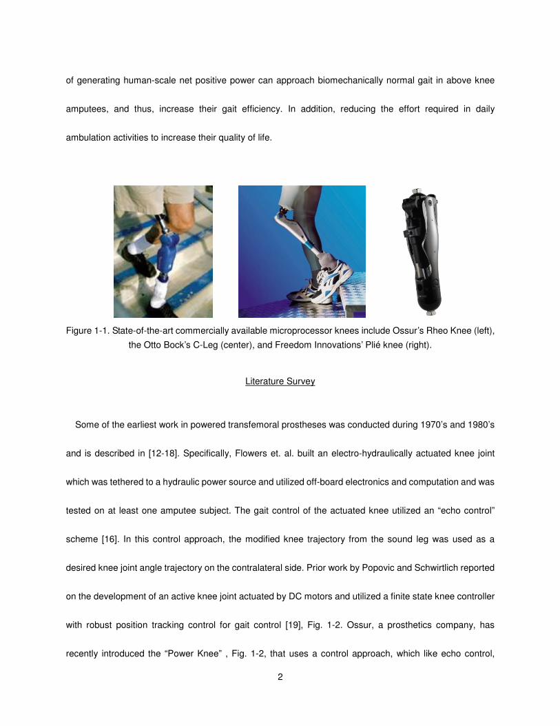
Figure 1-1. State-of-the-art commercially available microprocessor knees include Ossur’s Rheo Knee
(left), the Otto Bock’s C-Leg (center), and Freedom Innovations’ Plié knee (right). ................ 2
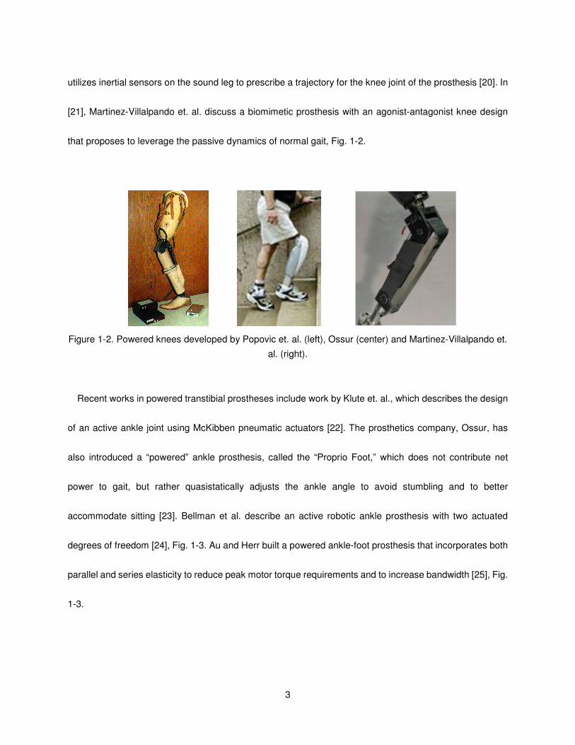
Figure 1-2. Powered knees developed by Popovic et. al. (left), Ossur (center) and Martinez-Villalpando et.
al. (right). .................................................................................................................................. 3
Figure 1-3. Prototype powered ankles developed by Bellman et. al. (left) and Au and Herr (right). ............ 4
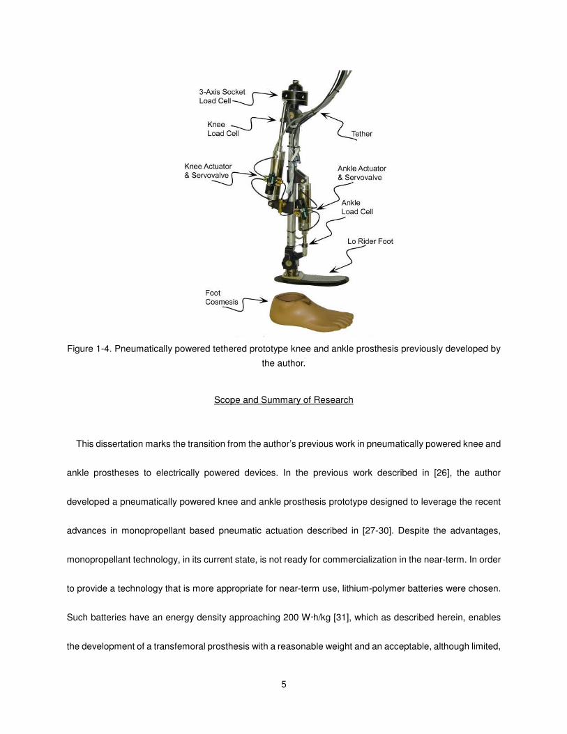
Figure 1-4. Pneumatically powered tethered prototype knee and ankle prosthesis previously developed by
the author. ................................................................................................................................ 5
Figure 2-1. The power tethered prototype. ................................................................................................. 15
Figure 2-2. The reduction of linear force output required by the ankle motor unit by the addition of a spring
in parallel for fast walking, taken from averaged normal biomechanical data [1]. ................. 16
Figure 2-3. Sagittal moment load cell, top and bottom views. .................................................................... 16
Figure 2-4. Sensorized prosthetic foot. ....................................................................................................... 17
Figure 2-5. The finite state switching model for impedance control. Blocks represent a state and arrows
represent the corresponding transitions. ............................................................................... 19
Figure 2-6. Able-bodied testing adapter used in the development of the prosthesis and controllers prior to
transfemoral amputee participation........................................................................................ 20
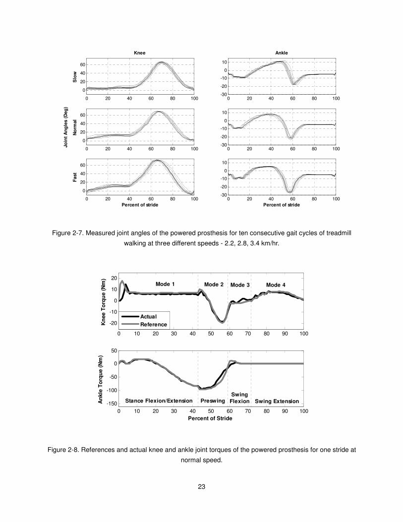
Figure 2-7. Measured joint angles of the powered prosthesis for ten consecutive gait cycles of treadmill
walking at three different speeds - 2.2, 2.8, 3.4 km/hr. .......................................................... 23
Figure 2-8. References and actual knee and ankle joint torques of the powered prosthesis for one stride at
normal speed. ........................................................................................................................ 23
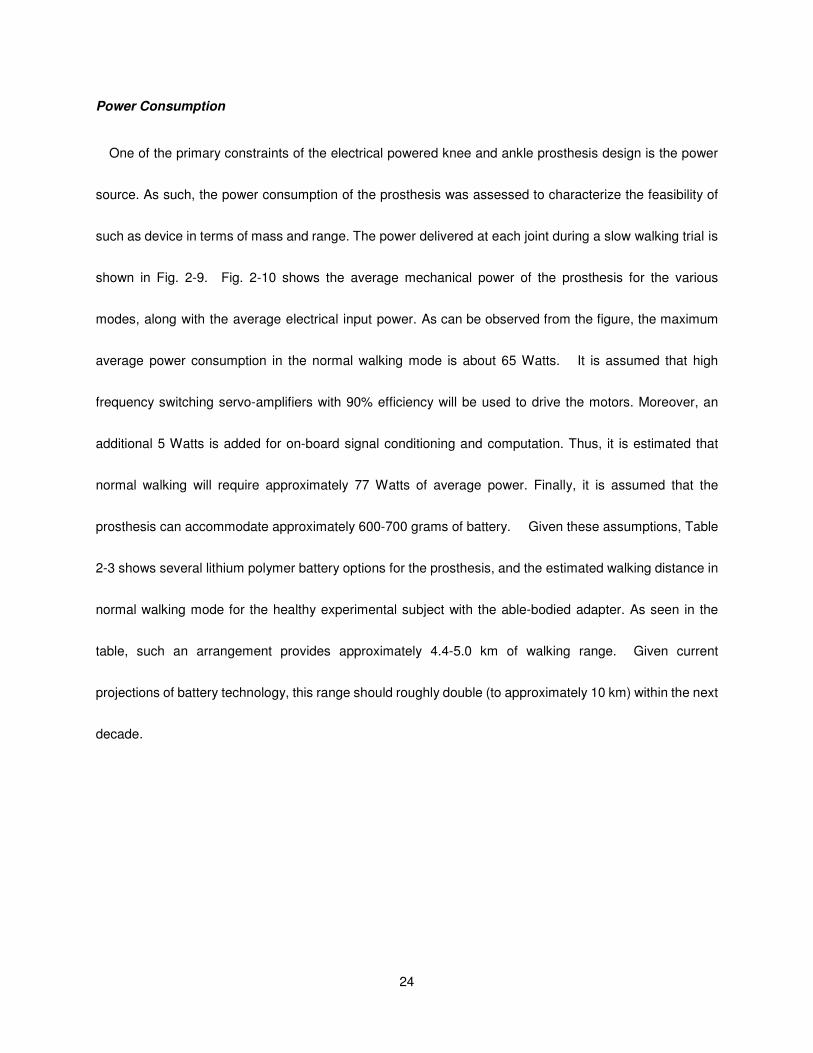
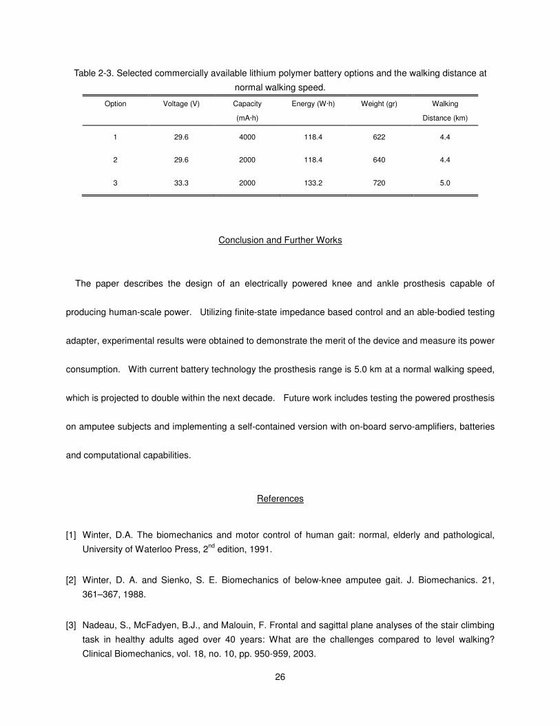
Figure 2-9. Measured mechanical power of the prosthesis for ten consecutive gait cycles of treadmill
walking at slow speed. ........................................................................................................... 25
Figure 2-10. Average electrical power consumption and mechanical power generation at the ankle and
knee of the powered prosthesis for standing and different walking speeds. ......................... 25
viii
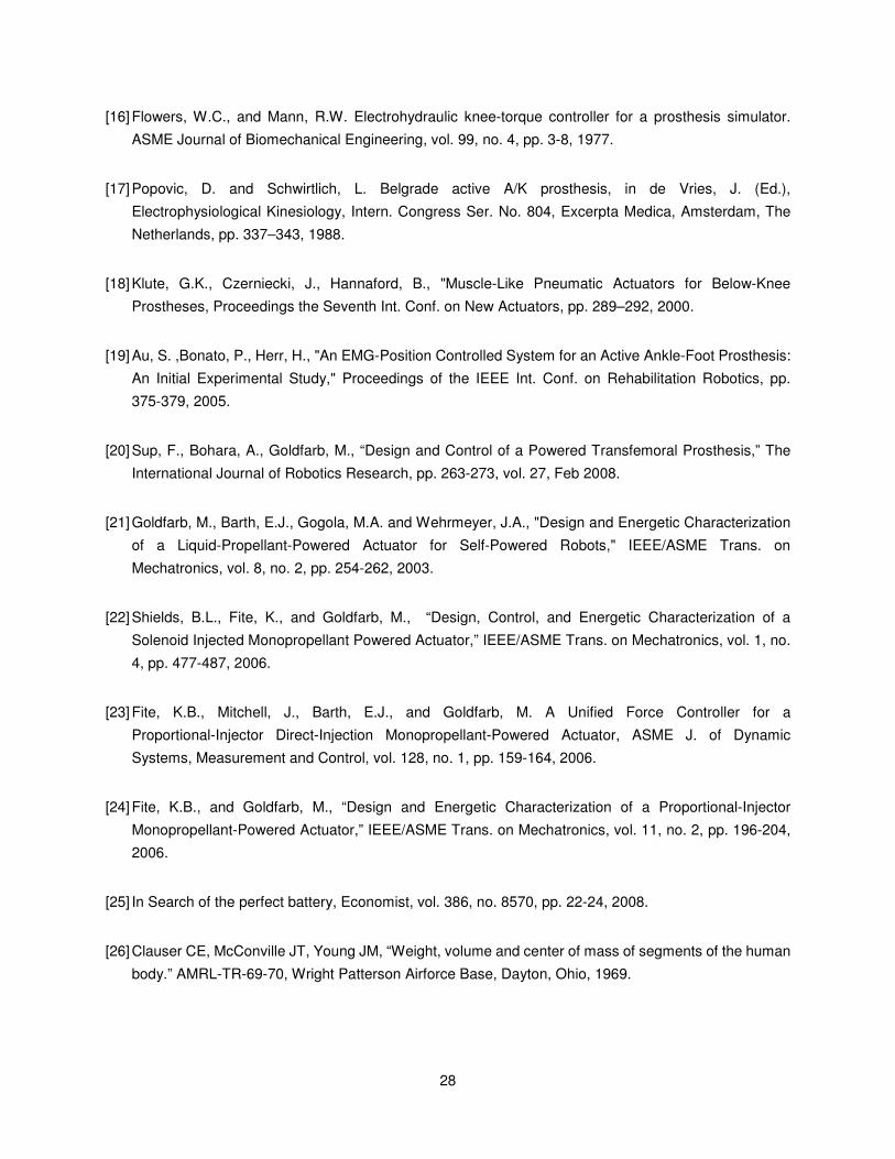
Figure 3-1. Normal biomechanical gait data for an 85 kg subject walking at a cadence of 80 steps per
minute [9]. .............................................................................................................................. 33
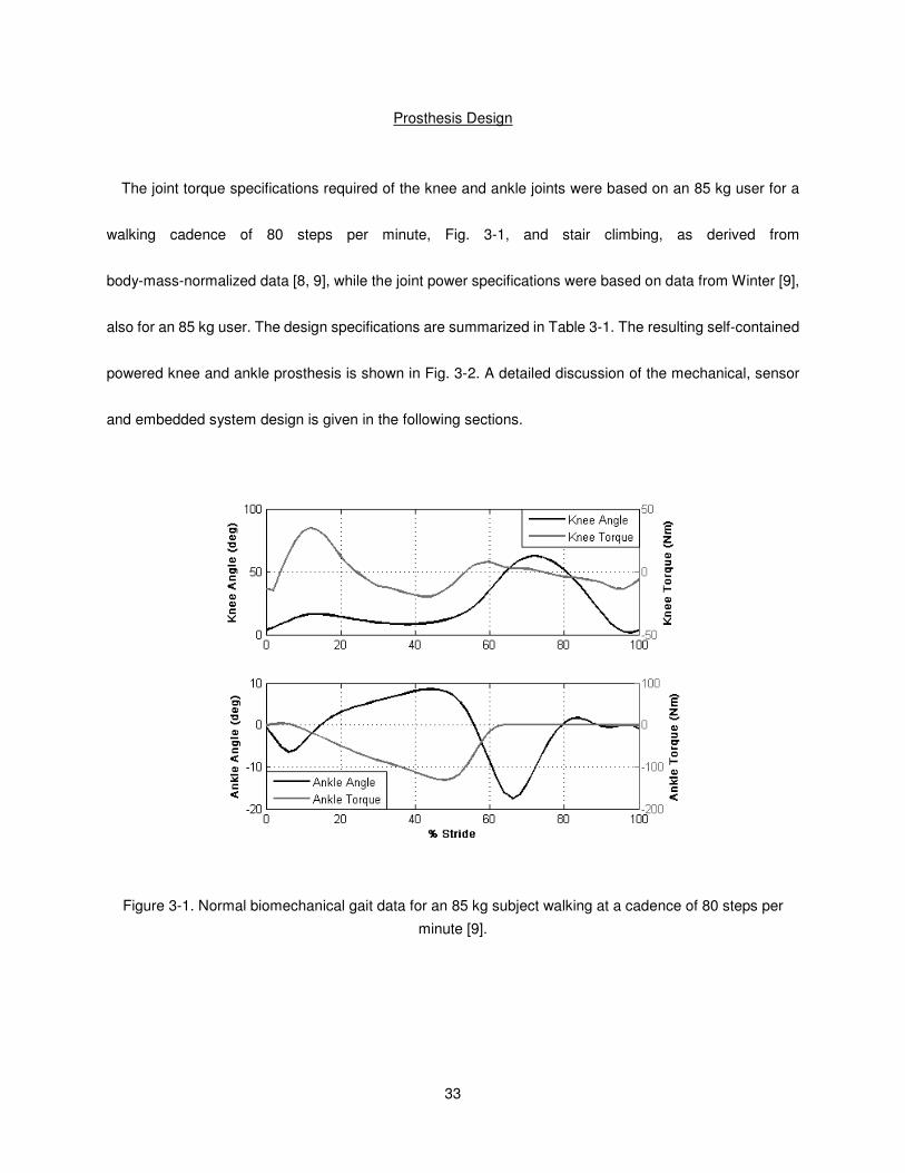
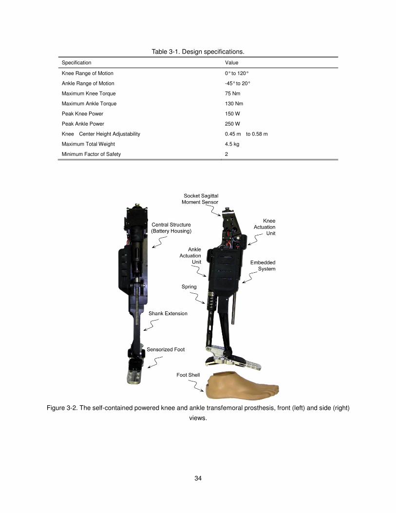
Figure 3-2. The self-contained powered knee and ankle transfemoral prosthesis, front (left) and side (right)
views. ..................................................................................................................................... 34
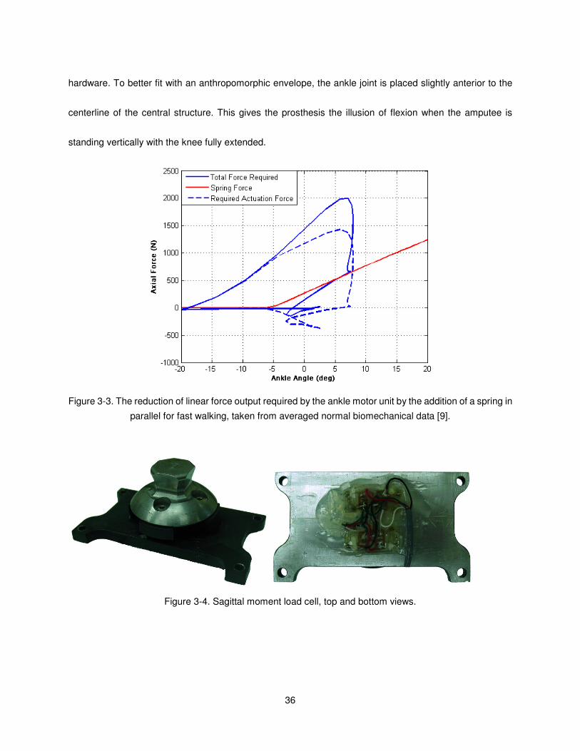
Figure 3-3. The reduction of linear force output required by the ankle motor unit by the addition of a spring
in parallel for fast walking, taken from averaged normal biomechanical data [9]. ................. 36
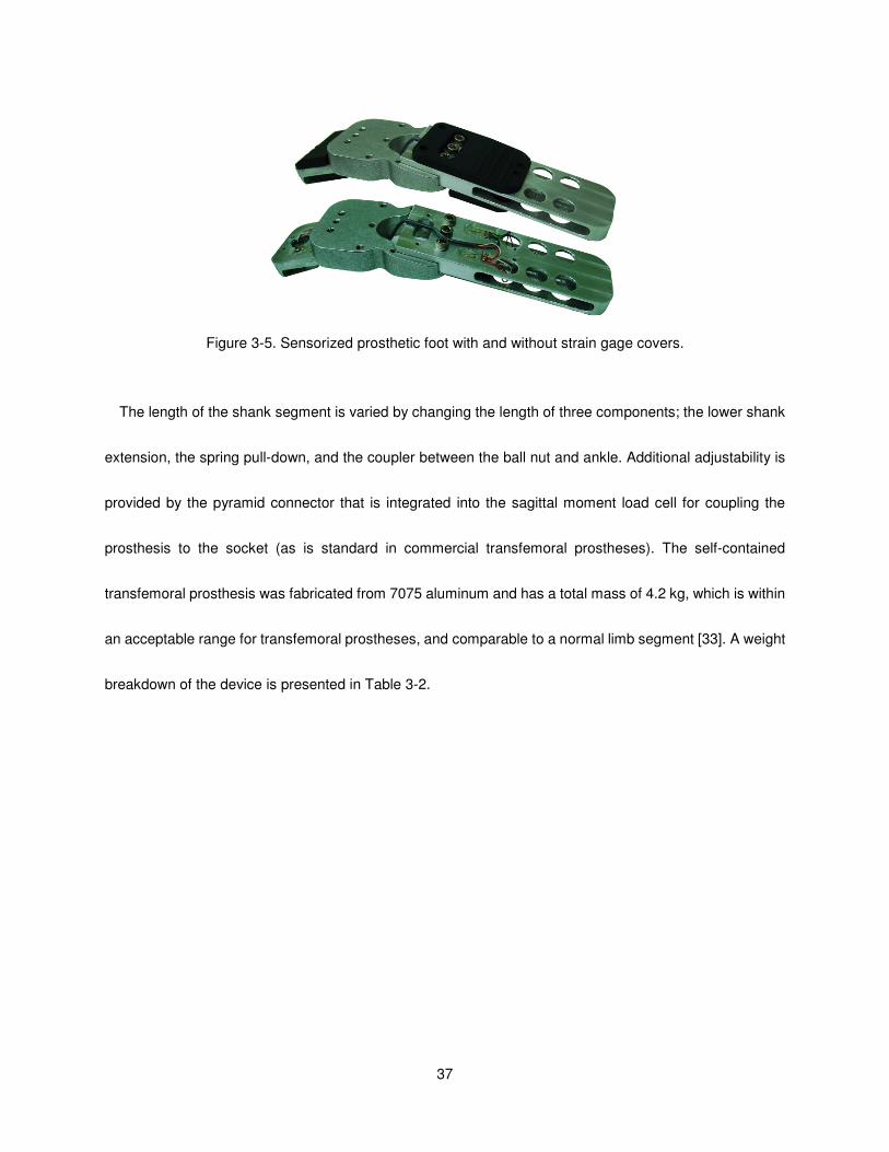
Figure 3-4. Sagittal moment load cell, top and bottom views. .................................................................... 36
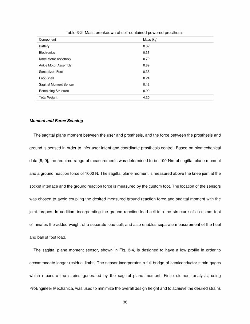
Figure 3-5. Sensorized prosthetic foot with and without strain gage covers. ............................................. 37
Figure 3-6. Embedded system framework. ................................................................................................. 40
Figure 3-7. Embedded system hardware with (right) and without (left) servo amplifiers. ........................... 42
Figure 3-8. Complete control architecture showing high, middle and low levels. ....................................... 43
Figure 3-9. The finite state machine for level walking. Blocks represent states and arrows represent the
corresponding transitions. ...................................................................................................... 45
Figure 3-10. The finite state machine for level standing. Blocks represent states and arrows represent the
corresponding transitions. ...................................................................................................... 45
Figure 3-11. Unilaterial transfemoral amputee test subject used for the powered prosthesis evaluation. . 46
Figure 3-12. Measured joint angles of the powered prosthesis for ten consecutive gait cycles of treadmill
walking at slow, normal and fast cadences, 64, 75, and 86 steps per minute, respectively. . 49
Fig. 3-13. Measured joint angles, torques and powers of the powered prosthesis for ten consecutive gait
cycles at self-selected speed (5.1 km/h at 87 steps per minute). .......................................... 51
Figure 3-14. References and actual knee and ankle joint torques of the powered prosthesis for one stride
at self-selected speed (5.1 km/hr at 87 steps per minute) on normal ground. ...................... 51
Figure 3-15. Measured electrical and mechanical power at the knee and ankle joints of the powered
prosthesis over one gait cycle at self-selected speed (5.1 km/hr at 87 steps per minute) on
normal ground. ....................................................................................................................... 52
Figure 3-16. Average electrical power consumption of the powered prosthesis for standing and walking at
self-selected speed (5.1 km/hr at 87 steps per minute) on normal ground. .......................... 54
Figure 4-1. The self-contained powered knee and ankle transfemoral prosthesis. ................................. 62
ix
Figure 4-2. Powered prosthesis control architecture. ................................................................................. 64
Figure 4-3. The state chart depicting the phase transitions in standing and sitting modes. ....................... 65
Figure 4-4. Knee angle modulated knee stiffness during sit-to-stand and stand-to-sit phases. ................. 66
Figure 4-5. Gaussian Mixture Model surface plots of the standing and sitting modes showing the regions of
the feature space, where the probability density function is greater than 0.05, for the three
dimensional PCA reduced data.............................................................................................. 74
Figure 4-6. Prosthetic knee angle (top) and the real-time activity mode switching (bottom) for a 90 seconds
standing and sitting trial. ........................................................................................................ 75
Figure 4-7. Knee and ankle angles (top), torques (middle) and powers (bottom) during sitting down. ...... 76
Figure 4-8. Knee and ankle angles (top), torques (middle) and powers (bottom) during standing up. ...... 76
Figure 4-9. Video frames of standing up (a) and sitting down (b) transitions. ............................................ 77
Figure 5-1. Powered prosthesis control architecture. ................................................................................. 83
Figure 5-2. The state chart depicting the phase transitions in walking mode. ............................................ 85
Figure 5-3. Comparison of normal biomechanical gait data for level [5] and upslope walking, 9 deg, [1] joint
angles and torques at the knee and ankle for a 75 kg subject. ............................................. 87
Figure 5-4. The self-contained powered knee and ankle transfemoral prosthesis. ................................. 88
Figure 5-5. Unilateral transfemoral amputee test subject used for the powered prosthesis evaluation. .... 89
Figure 5-6. Averaged joint angles, torques and powers of the powered prosthesis for ten consecutive gait
cycles at self-selected speed for level, 5, and 10 degrees walking. ...................................... 93
Figure 5-7. Measured joint angles of the powered prosthesis for five consecutive gait cycles at
self-selected speed for 10 degrees upslope walking. ............................................................ 93
Figure 5-8. Average electrical power consumption of the powered prosthesis for level, 5 deg, and 10 deg
upslope walking at self-selected speed on normal ground. ................................................... 94
x
LIST OF TABLES
Page
Table 2-1. Impedance parameters for walking from experimental tuning. Highlighted parameters vary with
walking speed. ........................................................................................................................... 21
Table 2-2. Impedance parameters for standing from experimental tuning. ................................................. 22
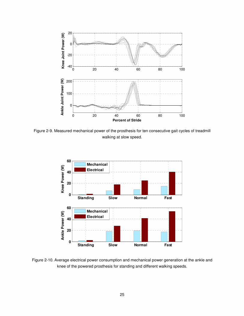
Table 2-3. Selected commercially available lithium polymer battery options and the walking distance at
normal walking speed. .............................................................................................................. 26
Table 3-1. Design specifications. ................................................................................................................ 34
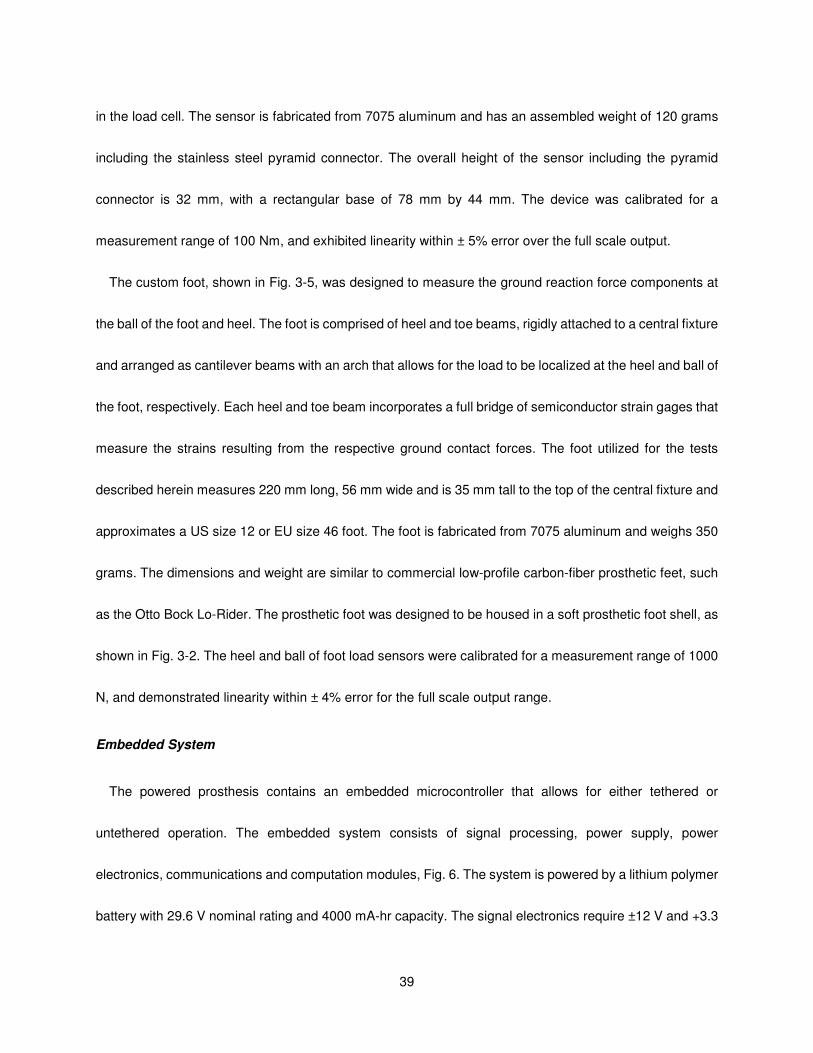
Table 3-2. Mass breakdown of self-contained powered prosthesis. ........................................................... 38
Table 3-3. Impedance parameters for treadmill walking from experimental tuning. ................................... 48
Table 3-4. Impedance parameters for standing from experimental tuning. ................................................. 48
Table 4-1. Impedance parameters for standing from experimental tuning. ................................................. 67
Table 4-2. Impedance parameters for sitting from experimental tuning. ..................................................... 67
Table 4-3. Different activity scenarios for database generation. ................................................................. 68
Table 5-1. Impedance parameters for walking from experimental tuning. .................................................. 91

1
CHAPTER I
Overview
Introduction and Motivation
There are more than 300,000 transfemoral amputees in the United States [1] (i.e., an incidence of
approximately one per thousand people), with 30,000 new transfemoral amputations conducted each year
[2]. If similar trends hold across the world population, one would expect approximately 7 million
transfemoral amputees worldwide. The lower limb amputee is faced with an extraordinary loss in power and
mobility post amputation. Perhaps the most significant limitation of existing prosthetic technologies is the
inability to provide net power at the joints. The loss of net power generation at the lower limb impairs the
ability of the prosthesis to restore biomechanically normal locomotive function during many locomotive
activities, including level walking, walking up stairs and slopes, running and jumping [3-10]. In the absence
of net power generation at the knee and ankle, transfemoral amputees with passive prostheses have been
shown to expend up to 60% more metabolic energy [11] and exert three times the affected-side hip power
and torque [9] when compared to healthy subjects during level walking.
The current generation of state-of-the-art prosthetic knee joints are microprocessor controlled dampers,
such as the Otto Bock C-Leg, Ossur Rheo Knee, and the Freedom Innovations Plié knee, Fig. 1-1. These
knee joints control either hydraulic or magnetic rheological fluid for the modulation of the damping in the
knee throughout the gait cycle. The highest functioning prosthetic ankles currently are carbon fiber springs
that provide limited ankle motion and are aimed at returning a small portion of power to the gait cycle. It is
the hypothesis of this work that the combination of actively powered knee and ankle joints with the capability
2
of generating human-scale net positive power can approach biomechanically normal gait in above knee
amputees, and thus, increase their gait efficiency. In addition, reducing the effort required in daily
ambulation activities to increase their quality of life.
Figure 1-1. State-of-the-art commercially available microprocessor knees include Ossur’s Rheo Knee (left),
the Otto Bock’s C-Leg (center), and Freedom Innovations’ Plié knee (right).
Literature Survey
Some of the earliest work in powered transfemoral prostheses was conducted during 1970’s and 1980’s
and is described in [12-18]. Specifically, Flowers et. al. built an electro-hydraulically actuated knee joint
which was tethered to a hydraulic power source and utilized off-board electronics and computation and was
tested on at least one amputee subject. The gait control of the actuated knee utilized an “echo control”
scheme [16]. In this control approach, the modified knee trajectory from the sound leg was used as a
desired knee joint angle trajectory on the contralateral side. Prior work by Popovic and Schwirtlich reported
on the development of an active knee joint actuated by DC motors and utilized a finite state knee controller
with robust position tracking control for gait control [19], Fig. 1-2. Ossur, a prosthetics company, has
recently introduced the “Power Knee” , Fig. 1-2, that uses a control approach, which like echo control,
3
utilizes inertial sensors on the sound leg to prescribe a trajectory for the knee joint of the prosthesis [20]. In
[21], Martinez-Villalpando et. al. discuss a biomimetic prosthesis with an agonist-antagonist knee design
that proposes to leverage the passive dynamics of normal gait, Fig. 1-2.
Figure 1-2. Powered knees developed by Popovic et. al. (left), Ossur (center) and Martinez-Villalpando et.
al. (right).
Recent works in powered transtibial prostheses include work by Klute et. al., which describes the design
of an active ankle joint using McKibben pneumatic actuators [22]. The prosthetics company, Ossur, has
also introduced a “powered” ankle prosthesis, called the “Proprio Foot,” which does not contribute net
power to gait, but rather quasistatically adjusts the ankle angle to avoid stumbling and to better
accommodate sitting [23]. Bellman et al. describe an active robotic ankle prosthesis with two actuated
degrees of freedom [24], Fig. 1-3. Au and Herr built a powered ankle-foot prosthesis that incorporates both
parallel and series elasticity to reduce peak motor torque requirements and to increase bandwidth [25], Fig.
1-3.

4
Figure 1-3. Prototype powered ankles developed by Bellman et. al. (left) and Au and Herr (right).
Unlike any of the aforementioned prior works, the author [26] describes a transfemoral prosthesis that
combines both a powered knee and ankle to restore mobility. The tethered pneumatically powered device,
Fig. 1-4, served as a laboratory test bed to develop the fundamental specifications and control for a
powered knee and ankle prosthesis. In this paper, the concept of a finite-state impedance based gait
controller is developed based on the use of passive impedance functions that coordinates the motion of the
prosthesis with the user during level walking.
5
Figure 1-4. Pneumatically powered tethered prototype knee and ankle prosthesis previously developed by
the author.
Scope and Summary of Research
This dissertation marks the transition from the author’s previous work in pneumatically powered knee and
ankle prostheses to electrically powered devices. In the previous work described in [26], the author
developed a pneumatically powered knee and ankle prosthesis prototype designed to leverage the recent
advances in monopropellant based pneumatic actuation described in [27-30]. Despite the advantages,
monopropellant technology, in its current state, is not ready for commercialization in the near-term. In order
to provide a technology that is more appropriate for near-term use, lithium-polymer batteries were chosen.
Such batteries have an energy density approaching 200 W·h/kg [31], which as described herein, enables
the development of a transfemoral prosthesis with a reasonable weight and an acceptable, although limited,
6
range of locomotion. The energy density of such batteries is expected to nearly double in the next decade
(driven largely by the automotive industry’s needs for electrical vehicles) [31], which will provide a
significantly improved range of locomotion. Prior to developing a self-contained powered knee and ankle
prosthesis, a tethered electrical powered knee and ankle prototype was built to explore the electrical power
requirements of such a device. Subsequently, a self-contained version of a powered knee and ankle
prosthesis was developed based on the specifications determined by the tethered prototype. Development
of the device included the mechanical design of the device, actuation assemblies, sensor package,
embedded electronics system, and a control strategy. The control of the device was refined to simplify the
finite-state impedance control structure for gait, accommodate varied speeds and incorporate non-gait
modes such as standing, sitting and the transitions between standing and sitting. Testing of the device was
performed via an able-bodied adapter for initial debugging and parameter tuning. Final testing was
performed with a single unilateral transfemoral amputee demonstrating the device on a treadmill and over
normal ground as well as slope ascent, standing, sitting and sit-to-stand transition modes.
Organization of the Document
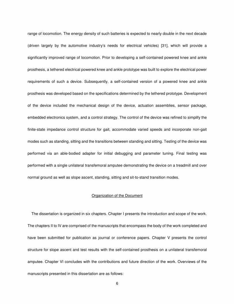
The dissertation is organized in six chapters. Chapter I presents the introduction and scope of the work.
The chapters II to IV are comprised of the manuscripts that encompass the body of the work completed and
have been submitted for publication as journal or conference papers. Chapter V presents the control
structure for slope ascent and test results with the self-contained prosthesis on a unilateral transfemoral
amputee. Chapter VI concludes with the contributions and future direction of the work. Overviews of the
manuscripts presented in this dissertation are as follows:

7
Manuscript 1: Design and Control of an Active Electrical Knee and Ankle Prosthesis
This paper presents an overview of the design and control of a tethered electrically powered knee and
ankle prosthesis. This prototype represents the transition point in the overall project from a pneumatically
powered knee and ankle prosthesis to electric. The tethered prototype was developed to validate the
electrically powered knee and ankle prosthesis concept and migrate the power source from pneumatic to an
electric. The work demonstrates the capabilities of the device via an able-bodied adapter that allows the
device to be worn by normal subjects. Projections from the study predicted reasonable power and energy
requirements for a self-contained electrical device supporting the development of a self-contained version.
Manuscript 1 is based on the following paper:
• F. Sup, H. A. Varol, J. Mitchell, T.J. Withrow, M. Goldfarb, “Design and Control of an Active Electrical
Knee and Ankle Prosthesis,” Proc. IEEE/RAS-EMBS Int. Conf. on Biomedical Robotics and
Biomechatronics , pp. 523-528, 2008.
Manuscript 2: Preliminary Evaluations of a Self-Contained Anthropomorphic Transfemoral Prosthesis
In this work, the detailed description and testing of an electrical self-contained powered knee and ankle
prosthesis are presented. The paper provides an overview of the main components of the prosthesis,
including the mechanical design, sensor development, embedded system, control architecture and
prototype testing. The prosthesis and control scheme are validated on a unilateral transfemoral amputee.
Experimental results are shown that demonstrate the ability to restore biomimetic gait patterns on the
prosthetic side and provide net power generation at the ankle over the gait cycle.
• F. Sup, H.A. Varol, and M. Goldfarb, “Preliminary Evaluations of a Self-Contained Anthropomorphic
Transfemoral Prosthesis,” IEEE/ASME Transactions on Mechatronics, 2009. Accepted.
Manuscript 3: Powered Sit-to-Stand and Assistive Stand-to-Sit Framework For a Powered Transfemoral

8
Prosthesis
This work presents a control framework for powered knee and ankle prosthesis during sitting and
standing and the transitions between the two states. Expanding the general control framework presented in
Manuscript 2, sitting, standing, powered sit-to-stand and assistive stand-to-sit are accomplished. The
control structure is implemented on the self-contained prosthesis presented in Manuscript 2 and tested on a
unilateral transfemoral amputee. Manuscript 3 is based on the following paper:
• H. A. Varol, F. Sup, and M. Goldfarb, “Powered Sit-to-Stand and Assistive Stand-to-Sit Framework for
a Powered Transfemoral Prosthesis,” IEEE 11th International Conference on Rehabilitation Robotics,
pp. 645-651, 2009.
References
[1] P. F. Adams, G. E. Hendershot, and M. A. Marano, “Current estimates from the National Health
Interview Survey, 1996,” National Center for Health Statistics. Vital Health Stat 10(200), 1999.
[2] J. Feinglass, J. L. Brown, A. LaSasso, M. W. Sohn, L. M. Manheim, S. J. Shah, and W. H. Pearce,
“Rates of lower-extremity amputation and arterial reconstruction in the United States, 1979 to
1996,” American J. of Public Health, vol. 89, no. 8, pp. 1222-1227, Aug, 1999.
[3] P. DeVita, M. Torry, K. L. Glover, and D. L. Speroni, “A functional knee brace alters joint torque and
power patterns during walking and running,” J. of Biomechanics, vol. 29, no. 5, pp. 583-588, May,
1996.
[4] R. Jacobs, M. F. Bobbert, and G. J. van Ingen Schenau, “Mechanical output from individual
muscles during explosive leg extensions: The role of biarticular muscles,” J. of Biomechanics, vol.
29, no. 4, pp. 513-523, Apr, 1996.
[5] S. Nadeau, B. J. McFadyen, and F. Malouin, “Frontal and sagittal plane analyses of the stair
climbing task in healthy adults aged over 40 years: what are the challenges compared to level
walking?,” Clinical Biomechanics, vol. 18, no. 10, pp. 950-959, Dec, 2003.
[6] A. Nagano, Y. Ishige, and S. Fukashiro, “Comparison of new approaches to estimate mechanical
output of individual joints in vertical jumps,” J. of Biomechanics, vol. 31, no. 10, pp. 951-955, Oct,
1998.
[7] B. I. Prilutsky, L. N. Petrova, and L. M. Raitsin, “Comparison of mechanical energy expenditure of
9
joint moments and muscle forces during human locomotion,” J. of Biomechanics, vol. 29, no. 4, pp.
405-415, Apr, 1996.
[8] R. Riener, M. Rabuffetti, and C. Frigo, “Joint powers in stair climbing at different slopes,” Proc. of
the First Joint BMES/EMBS Conf., vol. 1, pp. 530 vol.1, 1999.
[9] D. Winter, The Biomechanics and Motor Control of Human Gait: Normal, Elderly and Pathological,
2nd ed.: University of Waterloo Press, 1991.
[10] D. A. Winter, and S. E. Sienko, “Biomechanics of below-knee amputee gait,” J. of Biomechanics,
vol. 21, no. 5, pp. 361-367, 1988.
[11] R. L. Waters, J. Perry, D. Antonelli, and H. Hislop, “Energy cost of walking of amputees - Influence
of level of amputation,” J. of Bone and Joint Surgery-American Vol., vol. 58, no. 1, pp. 42-46, 1976.
[12] M. Donath, “Proportional EMG control for above knee prostheses,” Massachusetts Institute of
Tech. Dept. of Mechanical Eng. Thesis. M.S., 1974.
[13] W. C. Flowers, “A man-interactive simulator system for above-knee prosthetics studies,”
Massachusetts Institute of Tech. Dept. of Mechanical Eng. Thesis. Ph.D., 1973.
[14] W. C. Flowers, and R. W. Mann, “Electrohydraulic knee-torque controller for a prosthesis
simulator,” ASME J. of Biomechanical Engineering, vol. 99, no. 4, pp. 3-8, 1977.
[15] D. L. Grimes, “An active multi-mode above knee prosthesis controller,” Massachusetts Institute of
Tech. Dept. of Mechanical Eng. Thesis Ph.D., 1979.
[16] D. L. Grimes, W. C. Flowers, and M. Donath, “Feasibility of an active control scheme for above
knee prostheses,” ASME J. of Biomechanical Engineering, vol. 99, no. 4, pp. 215-221, 1977.
[17] J. L. Stein, and W. C. Flowers, “Stance phase-control of above-knee prostheses - Knee control
versus SACH foot design,” J. of Biomechanics, vol. 20, no. 1, pp. 19-28, 1987.
[18] J. L. Stein, and Massachusetts Institute of Technology. Dept. of Mechanical Engineering., “Design
issues in the stance phase control of above-knee prostheses,” Massachusetts Institute of Tech.
Dept. of Mechanical Eng. Thesis Ph.D., 1983.
[19] D. Popovic, and L. Schwirtlich, “Belgrade active A/K prosthesis,” in de Vries, J. (Ed.),
Electrophysiological Kinesiology, Intern. Congress Ser. No. 804, Excerpta Medica, Amsterdam,
The Netherlands, pp. 337-343, 1988.
[20] S. Bedard, and P. Roy, Actuated leg prosthesis for above-knee amputees, 7,314,490, U. S. Patent,
June 17, 2003.
10
[21] E. Martinez- Villalpando, J. Weber, G. Elliott, and H. Herr, “Design of an agonist-antagonist active
knee prosthesis,” Proc. IEEE/RAS-EMBS Int. Conf. on Biomedical Robotics and Biomechatronics,
pp. 529-534, 2008.
[22] G. K. Klute, J. Czerniecki, and B. Hannaford, “Muscle-like pneumatic actuators for below-knee
prostheses,” Proc. 7th Int. Conf. on New Actuators, pp. 289-292, 2000.
[23] W. Koniuk, Self-adusting prosthetic ankle apparatus, 6,443,993, U. S. Patent, March, 23, 2001.
[24] R. Bellman, A. Holgate, and T. Sugar, “SPARKy 3: Design of an active robotic ankle prosthesis
with two actuated degrees of freedom using regenerative kinetics,” Proc. IEEE/RAS-EMBS Int.
Conf. on Biomedical Robotics and Biomechatronics, pp. 511-516, 2008.
[25] S. Au, and H. Herr, “Powered ankle-foot prosthesis,” IEEE Robotics & Automation Magazine, vol.
15, pp. 52-59, 2008.
[26] F. Sup, A. Bohara, and M. Goldfarb, “Design and control of a powered transfemoral prosthesis,” Int.
J. of Robotics Research, vol. 27, no. 2, pp. 263-273, Feb, 2008.
[27] K. B. Fite, and M. Goldfarb, “Design and energetic characterization of a proportional-injector
monopropellant-powered actuator,” IEEE/ASME Trans. on Mechatronics, vol. 11, no. 2, pp.
196-204, Apr, 2006.
[28] K. B. Fite, J. E. Mitchell, E. J. Barth, and M. Goldfarb, “A unified force controller for a
proportional-injector direct-injection monopropellant-powered actuator,” J. of Dynamic Systems
Measurement and Control Trans. of ASME, vol. 128, no. 1, pp. 159-164, Mar, 2006.
[29] M. Goldfarb, E. J. Barth, M. A. Gogola, and J. A. Wehrmeyer, “Design and energetic
characterization of a liquid-propellant-powered actuator for self-powered robots,” IEEE/ASME
Trans. on Mechatronics, vol. 8, no. 2, pp. 254-262, 2003.
[30] B. L. Shields, K. B. Fite, and M. Goldfarb, “Design, control, and energetic characterization of a
solenoid-injected monopropellant-powered actuator,” IEEE/ASME Trans. on Mechatronics, vol. 11,
no. 4, pp. 477-487, Aug, 2006.
[31] “In search of the perfect battery,” Economist, vol. 386, no. 8570, pp. 22-24, 2008.
11
CHAPTER II
Manuscript 1: Design and Control of an Active Electrical Knee and Ankle
Prosthesis
Frank Sup,
Huseyin Atakan Varol, Jason Mitchell, Thomas J. Withrow and Michael Goldfarb
Vanderbilt University
Nashville, TN
Accepted as a Technical Paper to the
Proceedings of the 2008 IEEE/RAS-EMBS International Conference on
Biomedical Robotics and Biomechatronics

12
Abstract
This paper presents an overview of the design and control of an electrically powered knee and ankle
prosthesis. The prosthesis design incorporates two motor-driven ball screw units to drive the knee and
ankle joints. A spring in parallel with the ankle motor unit is employed to decrease the power consumption
and increase the torque output for a given motor size. The device's sensor package includes a custom
load cell to measure the sagittal socket interface moment above the knee joint, a custom sensorized foot to
measure the ground reaction force at the heel and ball of the foot, and commercial potentiometers and load
cells to measure joint positions and torques. A finite-state based impedance control approach, previously
developed by the authors, is used and experimental results on level treadmill walking are presented that
demonstrate the potential of the device to restore normal gait. The experimental power consumption of the
device projects a walking distance of 5.0 km at a speed of 2.8 km/hr with a lithium polymer battery pack.
Introduction
The native limb generates significant net power over a gait cycle in many locomotive functions including
walking, walking up stairs and slopes, running and jumping [1-8]. In the absence of net power generation,
transfemoral amputees with passive prosthesis have been shown to expend 60% more metabolic energy
[9] and exert three times the affected-side hip power and torque [1] when compared to healthy subjects
during level walking.
To the authors’ knowledge, the earliest powered transfemoral prosthesis was developed at MIT during
1970’s and 1980’s [10-16]. This prosthesis consisted of an electro-hydraulically actuated knee joint tethered
to a hydraulic power source and utilized off-board electronics and computation. As described in [13], an

13
“echo control” scheme was developed for gait control. In echo control, the modified knee trajectory from the
sound leg is played back on the contralateral side. Popovic and Schwirtlich reported the development of an
active knee joint actuated by DC motors [17]. They utilized a finite state knee controller with robust position
tracking control for gait control. In [18], the design of an active ankle joint using McKibben pneumatic
actuators is described. The feasibility of electromyography based position control approach for transtibial
prosthesis is assessed in [19]. Although no scientific literature is available, Ossur, a prosthetics company,
has recently made available a powered knee and a self-adjusting ankle. The “Power Knee” uses a control
approach similar to echo control, which utilizes sensors on the sound leg. The Ossur powered ankle
prosthesis, called the “Proprio Foot”, does not contribute net power to gait, but rather quasi-statically
adjusts the ankle angle to optimize gait.
The authors have developed a pneumatically powered knee and ankle prosthesis prototype, in which
they used finite state-based impedance control that only utilizes sensors on the prosthesis itself [20]. This
prototype was built to take advantage of the recent advances in monopropellant based pneumatic actuation
described by [21-24]. The authors believe that the monopropellant technology in its current state is not
ready for commercialization in the near-term. Current lithium-polymer batteries have an energy density
approaching 200 W·h/kg [25], which enable the development of a transfemoral prosthesis with a reasonable
weight and an acceptable, although limited, range of locomotion. The energy density of such batteries is
expected to nearly double in the next decade (driven largely by the automotive industry’s needs for
electrical vehicles) [25], which will provide a more generous range of locomotion.
In this paper, the authors describe progress toward the development of an electrically powered active
knee and ankle prosthesis. This prosthesis will be able to generate human-scale power at the joints and

14
incorporate a torque-based control framework for stable and coordinated interaction between the
prosthesis and the user. The paper describes the mechanical design of the prosthesis, provides an
overview of the finite-state based impedance control framework, presents experimental results on a healthy
subject using an able-bodied adapter, and discusses the electrical power requirements in different gait
modes.
Design Specifications
Prosthesis Prototype
The active joint torque specifications were based on an 85 kg user for fast walking and stair climbing, as
derived from body-mass-normalized data [1, 3]. The prosthesis is capable of 90° of flexion at the knee and
45° of planterflexion and 20° of dorsiflexion at the ankle. The electric powered prosthesis prototype is
presented in a labeled photograph, Fig. 1. The prosthesis is actuated by two motor-driven ball screw
assemblies that drive the knee and ankle joints, respectively, through a slider-crank linkage. Each actuation
unit consists of a Maxon motor (Model 148867) capable of producing 150 W of continuous power connected
to a 2mm lead ball screw of 10 mm and 12 mm diameters for the knee and ankle, respectively, via Oldham
couplings.
15
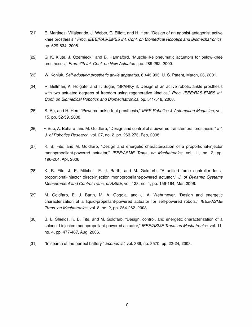
Figure 2-1. The power tethered prototype.
The ankle actuation unit additionally incorporates a spring of stiffness 1100 N/cm in parallel with the ball
screw, the purpose of which is to bias the motor’s axial force output toward ankle plantarflexion, and to
supplement power output during ankle push off. The resulting axial actuation unit’s force versus ankle
angle plot, Fig. 2-2, graphically demonstrates for fast walking the reduction in linear force output supplied by
the motor at the ankle through the addition of the spring. Note that the compression spring does not
engage until approximately five degrees of ankle plantarflexion. Each actuation unit additionally includes a
uniaxial load cell (Measurement Specialties ELPF-500L), positioned in series with the motor for force
control. Both the knee and ankle joints incorporate composite plain bearings (Garlock model DU) and, for
joint angle measurement, integrated precision potentiometers (ALPS RDC503013). A strain based

16
sagittal plane moment sensor, Fig. 2-3, is located between the knee joint and the socket connector, which
measures the moment between the socket and prosthesis. The ankle joint connects to a custom foot
design, Fig. 2-4, which incorporates strain gages to measure the ground reaction forces on the ball of the
foot and on the heel. The present prototype houses onboard signal conditioning electronics and relies on
a tether for power, computation and power electronics.
-25 -20 -15 -10 -5 0 5 10-1500
-1000
-500
0
500
1000
1500
2000
2500
Ankle Angle (deg)
Axia
l F
orc
e (N
)
Total Force Required
Spring Force
Motor Force Required
Figure 2-2. The reduction of linear force output required by the ankle motor unit by the addition of a spring in
parallel for fast walking, taken from averaged normal biomechanical data [1].
Figure 2-3. Sagittal moment load cell, top and bottom views.
17
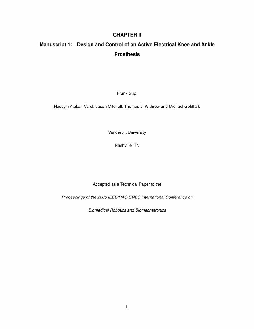
Figure 2-4. Sensorized prosthetic foot.
The knee height of device is varied by changing the main structural tube and the clamping supports for
the knee actuation unit and ankle spring. Additionally, the ankle joint and the sagittal moment load cell
incorporate standard pyramid connectors for coupling the prosthesis to the foot and socket, thus enabling a
high degree of adjustment in the knee and ankle alignment, as is standard in transfemoral prostheses.
Combined with the custom sensorized foot (0.35 kg) and foot shell (0.24 kg) the total weight of the tethered
transfemoral prosthesis is 3.8 kg, which is within an acceptable range for transfemoral prostheses, and less
than a comparable normal limb segment [26]. An untethered version incorporating batteries and on-board
electronics is expected to weigh less than 4.5 kg with further structural weight savings.
Moment and Force Sensing
The load between the user and prosthesis, and between the prosthesis and ground, is sensed in order to
infer user intent and enable prosthesis control. Based on the data presented in [1] and [4], the required
range of measurements was determined to be 100 Nm of sagittal plane moment and a ground reaction
force of 1000 N. The sagittal plane moment is measured above the knee joint at the socket interface and
the ground reaction force is measured by the sensorized foot. The location of the sensors was chosen to
18
avoid coupling the desired measured ground reaction force and sagittal moment with the joint torques. In
addition, incorporating the ground reaction load cell into the structure of a custom foot itself eliminates the
added weight of a separate load cell.
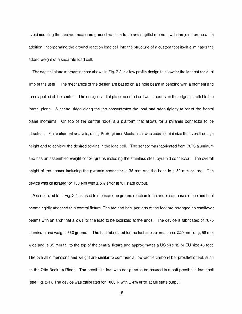
The sagittal plane moment sensor shown in Fig. 2-3 is a low profile design to allow for the longest residual
limb of the user. The mechanics of the design are based on a single beam in bending with a moment and
force applied at the center. The design is a flat plate mounted on two supports on the edges parallel to the
frontal plane. A central ridge along the top concentrates the load and adds rigidity to resist the frontal
plane moments. On top of the central ridge is a platform that allows for a pyramid connector to be
attached. Finite element analysis, using ProEngineer Mechanica, was used to minimize the overall design
height and to achieve the desired strains in the load cell. The sensor was fabricated from 7075 aluminum
and has an assembled weight of 120 grams including the stainless steel pyramid connector. The overall
height of the sensor including the pyramid connector is 35 mm and the base is a 50 mm square. The
device was calibrated for 100 Nm with ± 5% error at full state output.
A sensorized foot, Fig. 2-4, is used to measure the ground reaction force and is comprised of toe and heel
beams rigidly attached to a central fixture. The toe and heel portions of the foot are arranged as cantilever
beams with an arch that allows for the load to be localized at the ends. The device is fabricated of 7075
aluminum and weighs 350 grams. The foot fabricated for the test subject measures 220 mm long, 56 mm
wide and is 35 mm tall to the top of the central fixture and approximates a US size 12 or EU size 46 foot.
The overall dimensions and weight are similar to commercial low-profile carbon-fiber prosthetic feet, such
as the Otto Bock Lo-Rider. The prosthetic foot was designed to be housed in a soft prosthetic foot shell
(see Fig. 2-1). The device was calibrated for 1000 N with ± 4% error at full state output.
19
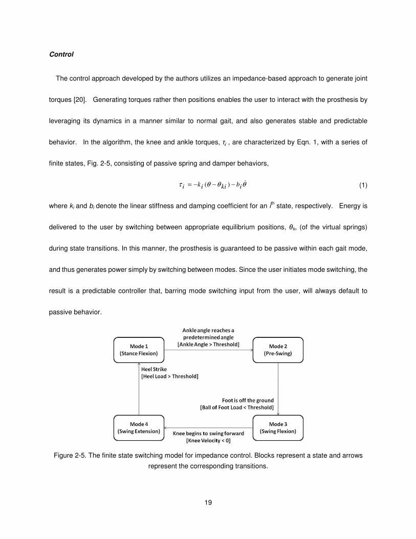
Control
The control approach developed by the authors utilizes an impedance-based approach to generate joint
torques [20]. Generating torques rather then positions enables the user to interact with the prosthesis by
leveraging its dynamics in a manner similar to normal gait, and also generates stable and predictable
behavior. In the algorithm, the knee and ankle torques, τi , are characterized by Eqn. 1, with a series of
finite states, Fig. 2-5, consisting of passive spring and damper behaviors,
θθθτ &ibkiiki −−−= )( (1)
where ki and bi denote the linear stiffness and damping coefficient for an ith state, respectively. Energy is
delivered to the user by switching between appropriate equilibrium positions, θk, (of the virtual springs)
during state transitions. In this manner, the prosthesis is guaranteed to be passive within each gait mode,
and thus generates power simply by switching between modes. Since the user initiates mode switching, the
result is a predictable controller that, barring mode switching input from the user, will always default to
passive behavior.
Figure 2-5. The finite state switching model for impedance control. Blocks represent a state and arrows
represent the corresponding transitions.
20
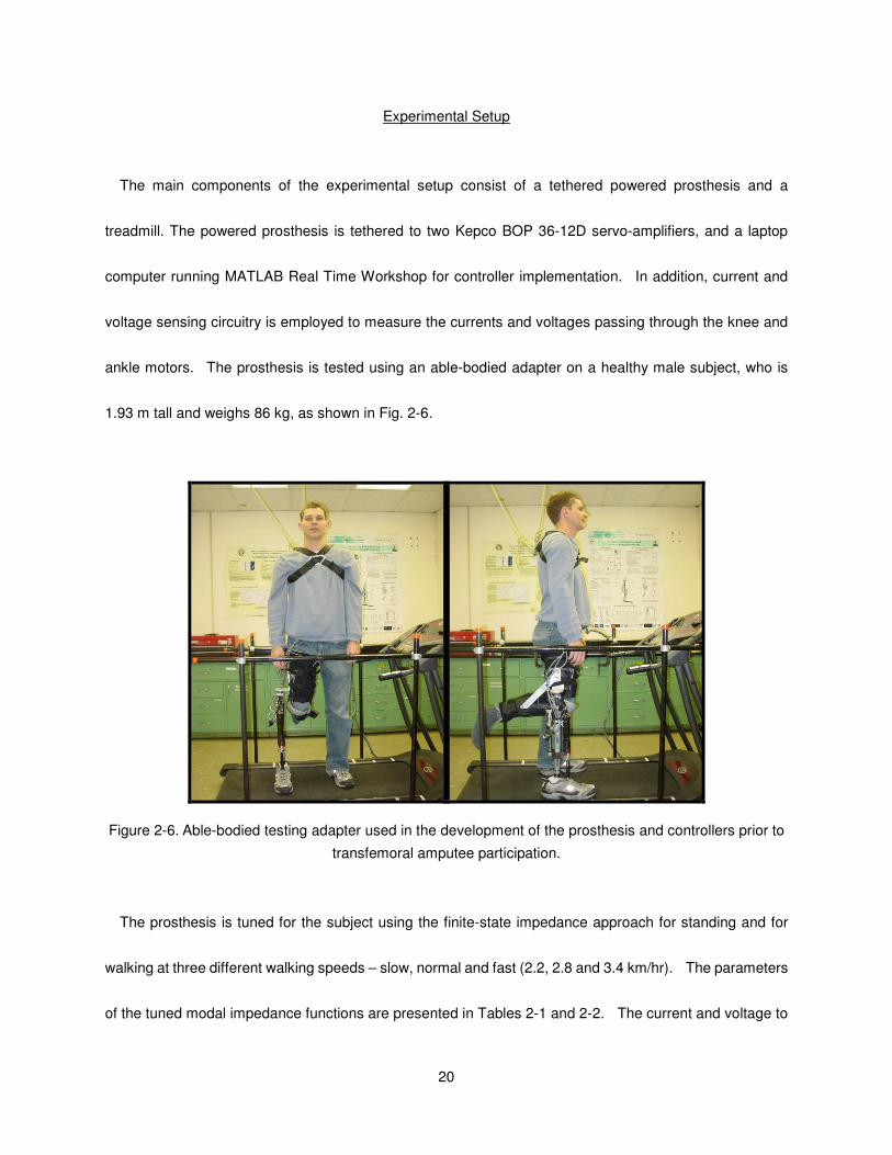
Experimental Setup
The main components of the experimental setup consist of a tethered powered prosthesis and a
treadmill. The powered prosthesis is tethered to two Kepco BOP 36-12D servo-amplifiers, and a laptop
computer running MATLAB Real Time Workshop for controller implementation. In addition, current and
voltage sensing circuitry is employed to measure the currents and voltages passing through the knee and
ankle motors. The prosthesis is tested using an able-bodied adapter on a healthy male subject, who is
1.93 m tall and weighs 86 kg, as shown in Fig. 2-6.
Figure 2-6. Able-bodied testing adapter used in the development of the prosthesis and controllers prior to
transfemoral amputee participation.
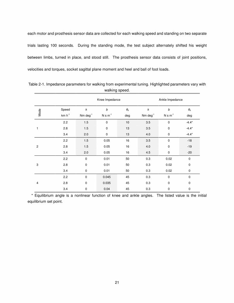
The prosthesis is tuned for the subject using the finite-state impedance approach for standing and for
walking at three different walking speeds – slow, normal and fast (2.2, 2.8 and 3.4 km/hr). The parameters
of the tuned modal impedance functions are presented in Tables 2-1 and 2-2. The current and voltage to
21
each motor and prosthesis sensor data are collected for each walking speed and standing on two separate
trials lasting 100 seconds. During the standing mode, the test subject alternately shifted his weight
between limbs, turned in place, and stood still. The prosthesis sensor data consists of joint positions,
velocities and torques, socket sagittal plane moment and heel and ball of foot loads.
Table 2-1. Impedance parameters for walking from experimental tuning. Highlighted parameters vary with
walking speed.
Knee Impedance Ankle Impedance
Mode
Speed
km h-1
k
Nm deg-1
b
N s m-1
θk
deg
k
Nm deg-1
b
N s m-1
θk
deg
1
2.2 1.5 0 10 3.5 0 -4.4*
2.8 1.5 0 13 3.5 0 -4.4*
3.4 2.0 0 13 4.0 0 -4.4*
2
2.2 1.5 0.05 16 3.5 0 -18
2.8 1.5 0.05 16 4.0 0 -19
3.4 2.0 0.05 16 4.5 0 -20
3
2.2 0 0.01 50 0.3 0.02 0
2.8 0 0.01 50 0.3 0.02 0
3.4 0 0.01 50 0.3 0.02 0
4
2.2 0 0.045 45 0.3 0 0
2.8 0 0.035 45 0.3 0 0
3.4 0 0.04 45 0.3 0 0
* Equilibrium angle is a nonlinear function of knee and ankle angles. The listed value is the initial
equilibrium set point.

22
Table 2-2. Impedance parameters for standing from experimental tuning.
Knee Impedance Ankle Impedance
Mode k
Nm deg-1
b
N s m-1
θk
deg
k
Nm deg-1
b
N s m-1
θk
deg
Ground Contact 2.0 0.05 5 5.0 0 -4
No Ground Contact 0 0.02 5 2.0 0 -4
Results and Discussion
Performance
Measured joint angles from the prosthesis’ onboard sensors during level treadmill walking at 2.2, 2.8,
and 3.4 km/hr are presented in Fig. 2-7. In comparing the knee and ankle angles to the prototypical data
[1], one can observe that the powered prosthesis and controller provide behavior quite similar to normal
gait. The knee and ankle torque trajectories with references are presented in Fig. 2-8, demonstrating
capabilities of the electric prosthesis to produce the requisite forces.
23
0 20 40 60 80 100
0
20
40
60
Knee
Slo
w
0 20 40 60 80 100-30
-20
-10
0
10
Ankle
0 20 40 60 80 100
0
20
40
60
No
rmal
0 20 40 60 80 100-30
-20
-10
0
10
0 20 40 60 80 100
0
20
40
60
Percent of stride
Fast
0 20 40 60 80 100-30
-20
-10
0
10
Percent of stride
Jo
int
An
gle
s (
Deg
)
Figure 2-7. Measured joint angles of the powered prosthesis for ten consecutive gait cycles of treadmill
walking at three different speeds - 2.2, 2.8, 3.4 km/hr.
0 10 20 30 40 50 60 70 80 90 100
-20
-10
0
10
20Mode 1 Mode 2 Mode 3 Mode 4
Kn
ee T
orq
ue (
Nm
)
0 10 20 30 40 50 60 70 80 90 100
-150
-100
-50
0
50
Percent of Stride
An
kle
To
rqu
e (
Nm
)
Stance Flexion/Extension Preswing Swing
Flexion Swing Extension
Actual
Reference
Figure 2-8. References and actual knee and ankle joint torques of the powered prosthesis for one stride at
normal speed.
24
Power Consumption
One of the primary constraints of the electrical powered knee and ankle prosthesis design is the power
source. As such, the power consumption of the prosthesis was assessed to characterize the feasibility of
such as device in terms of mass and range. The power delivered at each joint during a slow walking trial is
shown in Fig. 2-9. Fig. 2-10 shows the average mechanical power of the prosthesis for the various
modes, along with the average electrical input power. As can be observed from the figure, the maximum
average power consumption in the normal walking mode is about 65 Watts. It is assumed that high
frequency switching servo-amplifiers with 90% efficiency will be used to drive the motors. Moreover, an
additional 5 Watts is added for on-board signal conditioning and computation. Thus, it is estimated that
normal walking will require approximately 77 Watts of average power. Finally, it is assumed that the
prosthesis can accommodate approximately 600-700 grams of battery. Given these assumptions, Table
2-3 shows several lithium polymer battery options for the prosthesis, and the estimated walking distance in
normal walking mode for the healthy experimental subject with the able-bodied adapter. As seen in the
table, such an arrangement provides approximately 4.4-5.0 km of walking range. Given current
projections of battery technology, this range should roughly double (to approximately 10 km) within the next
decade.
25
0 20 40 60 80 100-40
-20
0
20
Kn
ee J
oin
t P
ow
er
(W)
0 20 40 60 80 100
0
100
200
An
kle
Jo
int
Po
wer
(W)
Percent of Stride
Figure 2-9. Measured mechanical power of the prosthesis for ten consecutive gait cycles of treadmill
walking at slow speed.
Standing Slow Normal Fast0
20
40
60
Kn
ee P
ow
er
(W)
Mechanical
Electrical
Standing Slow Normal Fast0
20
40
60
An
kle
Po
wer
(W)
Mechanical
Electrical
Figure 2-10. Average electrical power consumption and mechanical power generation at the ankle and
knee of the powered prosthesis for standing and different walking speeds.
26
Table 2-3. Selected commercially available lithium polymer battery options and the walking distance at
normal walking speed.
Option Voltage (V) Capacity
(mA·h)
Energy (W·h) Weight (gr) Walking
Distance (km)
1 29.6 4000 118.4 622 4.4
2 29.6 2000 118.4 640 4.4
3 33.3 2000 133.2 720 5.0
Conclusion and Further Works
The paper describes the design of an electrically powered knee and ankle prosthesis capable of
producing human-scale power. Utilizing finite-state impedance based control and an able-bodied testing
adapter, experimental results were obtained to demonstrate the merit of the device and measure its power
consumption. With current battery technology the prosthesis range is 5.0 km at a normal walking speed,
which is projected to double within the next decade. Future work includes testing the powered prosthesis
on amputee subjects and implementing a self-contained version with on-board servo-amplifiers, batteries
and computational capabilities.
References
[1] Winter, D.A. The biomechanics and motor control of human gait: normal, elderly and pathological,
University of Waterloo Press, 2nd
edition, 1991.
[2] Winter, D. A. and Sienko, S. E. Biomechanics of below-knee amputee gait. J. Biomechanics. 21,
361–367, 1988.
[3] Nadeau, S., McFadyen, B.J., and Malouin, F. Frontal and sagittal plane analyses of the stair climbing
task in healthy adults aged over 40 years: What are the challenges compared to level walking?
Clinical Biomechanics, vol. 18, no. 10, pp. 950-959, 2003.

27
[4] Riener, R., Rabuffetti, M., and Frigo, C. Joint powers in stair climbing at different slopes. Proceedings
of the IEEE International Conference on Engineering in Medicine and Biology, vol. 1, p. 530, 1999.
[5] Prilutsky, B.I., Petrova, L.N., and Raitsin, L.M. Comparison of mechanical energy expenditure of joint
moments and muscle forces during human locomotion. Journal of Biomechanics, vol. 29, no. 4, pp.
405-415, 1996.
[6] DeVita, P., Torry M., Glover, K.L., and Speroni, D.L. A Functional Knee Brace Alters Joint Torque
and Power Patterns during Walking and Running, Journal of Biomechanics, vol. 29, no. 5, pp.
583-588, 1996.
[7] Nagano, A., Ishige, Y., and Fukashiro, S. Comparison of new approaches to estimate mechanical
output of individual joints in vertical jumps. Journal of Biomechanics, vol. 31, no. 10, pp. 951-955,
1998.
[8] Jacobs, R., Bobbert, M.F., van Ingen Schenau, G.J. Mechanical output from individual muscles during
explosive leg extensions: the role of biarticular muscles. Journal of Biomechanics, vol. 29, no. 4, pp.
513-523, 1996.
[9] Waters, R., Perry, J., Antonelli, D., and Hislop, H. Energy cost of walking amputees: the influence of
level of amputation. J. Bone and Joint Surgery. 58A, 42–46, 1976.
[10] Flowers, W.C., A Man-Interactive Simulator System for Above-Knee Prosthetics Studies, Department
of Mechanical Engineering PhD Thesis, MIT, 1973.
[11] Donath, M., Proportional EMG Control for Above-Knee Prosthesis’, Department of Mechanical
Engineering Masters Thesis, MIT, 1972.
[12] Grimes, D. L. An Active Multi-Mode Above Knee Prosthesis Controller. Department of Mechanical
Engineering PhD Thesis, MIT, 1979.
[13] Grimes, D. L., Flowers, W. C., and Donath, M. Feasibility of an active control scheme for above knee
prostheses. ASME Journal of Biomechanical Engineering, vol. 99, no. 4, pp. 215-221, 1977.
[14] Stein, J.L. Design Issues in the Stance Phase Control of Above-Knee Prostheses. Department of
Mechanical Engineering PhD Thesis, MIT, 1983
[15] Stein, J.L., and Flowers, W.C. Stance phase control of above-knee prostheses: knee control versus
SACH foot design. Journal of Biomechanics, vol. 20, no. 1, pp. 19-28, 1987.
28
[16] Flowers, W.C., and Mann, R.W. Electrohydraulic knee-torque controller for a prosthesis simulator.
ASME Journal of Biomechanical Engineering, vol. 99, no. 4, pp. 3-8, 1977.
[17] Popovic, D. and Schwirtlich, L. Belgrade active A/K prosthesis, in de Vries, J. (Ed.),
Electrophysiological Kinesiology, Intern. Congress Ser. No. 804, Excerpta Medica, Amsterdam, The
Netherlands, pp. 337–343, 1988.
[18] Klute, G.K., Czerniecki, J., Hannaford, B., "Muscle-Like Pneumatic Actuators for Below-Knee
Prostheses, Proceedings the Seventh Int. Conf. on New Actuators, pp. 289–292, 2000.
[19] Au, S. ,Bonato, P., Herr, H., "An EMG-Position Controlled System for an Active Ankle-Foot Prosthesis:
An Initial Experimental Study," Proceedings of the IEEE Int. Conf. on Rehabilitation Robotics, pp.
375-379, 2005.
[20] Sup, F., Bohara, A., Goldfarb, M., “Design and Control of a Powered Transfemoral Prosthesis,” The
International Journal of Robotics Research, pp. 263-273, vol. 27, Feb 2008.
[21] Goldfarb, M., Barth, E.J., Gogola, M.A. and Wehrmeyer, J.A., "Design and Energetic Characterization
of a Liquid-Propellant-Powered Actuator for Self-Powered Robots," IEEE/ASME Trans. on
Mechatronics, vol. 8, no. 2, pp. 254-262, 2003.
[22] Shields, B.L., Fite, K., and Goldfarb, M., “Design, Control, and Energetic Characterization of a
Solenoid Injected Monopropellant Powered Actuator,” IEEE/ASME Trans. on Mechatronics, vol. 1, no.
4, pp. 477-487, 2006.
[23] Fite, K.B., Mitchell, J., Barth, E.J., and Goldfarb, M. A Unified Force Controller for a
Proportional-Injector Direct-Injection Monopropellant-Powered Actuator, ASME J. of Dynamic
Systems, Measurement and Control, vol. 128, no. 1, pp. 159-164, 2006.
[24] Fite, K.B., and Goldfarb, M., “Design and Energetic Characterization of a Proportional-Injector
Monopropellant-Powered Actuator,” IEEE/ASME Trans. on Mechatronics, vol. 11, no. 2, pp. 196-204,
2006.
[25] In Search of the perfect battery, Economist, vol. 386, no. 8570, pp. 22-24, 2008.
[26] Clauser CE, McConville JT, Young JM, “Weight, volume and center of mass of segments of the human
body.” AMRL-TR-69-70, Wright Patterson Airforce Base, Dayton, Ohio, 1969.

29
CHAPTER III
Manuscript 2: Preliminary Evaluations of a Self-Contained Anthropomorphic
Transfemoral Prosthesis
Frank Sup,
Huseyin Atakan Varol, Jason Mitchell, Thomas J. Withrow and Michael Goldfarb
Vanderbilt University
Nashville, TN
Accepted as a Regular Paper to the
IEEE/ASME Transactions on Mechatronics
in the focused section
Anthropomorphism in Mechatronic Systems

30
Abstract
This paper presents a self-contained powered knee and ankle prosthesis, intended to enhance the
mobility of transfemoral amputees. A finite-state based impedance control approach, previously developed
by the authors, is used for the control of the prosthesis during walking and standing. Experiments on an
amputee subject for level treadmill and overground walking are described. Knee and ankle joint angle,
torque, and power data taken during walking experiments at various speeds demonstrate the ability of the
prosthesis to provide a functional gait that is representative of normal gait biomechanics. Measurements
from the battery during level overground walking indicate that the self-contained device can provide over
4,500 strides, or 9 km, of walking at a speed of 5.1 km/h between battery charges.
Introduction
There are more than 300,000 transfemoral amputees [1] in the United States (i.e., an incidence of
approximately one per thousand people), with 30,000 new transfemoral amputations conducted each year
[2]. If similar trends hold across the world population, then one would expect approximately 7 million
transfemoral amputees worldwide. One of the most significant limitations of current prosthetic technology is
the inability to provide net power at the joints. This loss of net power generation at the lower limb impairs the
ability of the prosthesis to restore biomechanically normal locomotive function during many locomotive
activities, including level walking, walking up stairs and slopes, running and jumping [3-10]. In the absence
of net power generation at the knee and ankle, transfemoral amputees with passive prostheses have been
shown to expend 60% more metabolic energy [11] and exert three times the affected-side hip power and

31
torque [9] when compared to healthy subjects during level walking. It is the hypothesis of this work that an
actively powered knee and ankle prosthesis with the capability of generating human-scale net positive
power over a gait cycle will provide improved functional restoration relative to passive prostheses.
Some of the earliest work in powered transfemoral prostheses was conducted during 1970’s and 1980’s
and is described in [12-18]. Specifically, an electro-hydraulically actuated knee joint, which was tethered to
a hydraulic power source and utilized off-board electronics and computation, was developed and tested on
at least one amputee subject. As described in [16], an “echo control” scheme was developed for gait
control. In this control approach, the modified knee trajectory from the sound leg was used as a desired
knee joint angle trajectory on the contralateral side. Other prior work reported the development of an active
knee joint actuated by DC motors and utilized a finite state knee controller with robust position tracking
control for gait control [19]. Ossur, a prosthetics company, has recently introduced the “Power Knee” that
uses a control approach, which like echo control, utilizes sensors on the sound leg to prescribe a trajectory
for the knee joint of the prosthesis [20]. In [21], the authors discuss a biomimetic prosthesis with an
agonist-antagonist knee.
Work in powered transtibial prostheses includes [22], which describes the design of an active ankle joint
using McKibben pneumatic actuators. Ossur has also introduced a “powered” ankle prosthesis, called the
“Proprio Foot,” which does not contribute net power to gait, but rather quasistatically adjusts the ankle angle
to avoid stumbling and to better accommodate sitting [23]. Bellman et al. describe an active robotic ankle
prosthesis with two actuated degrees of freedom [24]. Au and Herr built a powered ankle-foot prosthesis
that incorporates both parallel and series elasticity to reduce peak motor torque requirements and to
increase bandwidth [25].

32
Unlike any of the aforementioned prior works, this paper describes a transfemoral prosthesis with both a
powered knee and ankle. Note that, as described by Sup et al. [26], the authors have developed previously
a pneumatically powered knee and ankle prosthesis prototype, which was designed to leverage recent
advances in monopropellant based pneumatic actuation described [27-30]. Despite this, the authors
believe that the monopropellant technology in its current state is not ready for commercialization in the
near-term. In order to provide a technology that is more appropriate for near-term use, the authors describe
in this paper a powered knee and ankle prosthesis powered by a lithium-polymer battery. Such batteries
have an energy density approaching 200 W·h/kg [31], which as described herein, enables the development
of a transfemoral prosthesis with a reasonable weight and an acceptable, although limited, range of
locomotion. The energy density of such batteries is expected to nearly double in the next decade (driven
largely by the automotive industry’s needs for electrical vehicles) [31], which will provide a significantly
improved range of locomotion. Prior to developing the self-contained, battery-powered powered knee and
ankle prosthesis described herein, Sup et al. [32] previously built a tethered electrical powered knee and
ankle prototype to explore the electrical power requirements of such a device.
Based on this preliminary work, the authors have developed an electrically powered self-contained active
knee and ankle prosthesis, which is described herein. The self-contained prosthesis generates
human-scale power at the joints and incorporates a torque-based control framework for stable and
coordinated interaction between the prosthesis and the user. This paper describes the mechanical and
electrical design of the prosthesis, provides an overview of the finite-state based impedance control
framework for walking and standing, presents experimental results on a single transfemoral amputee
subject, and discusses the electrical power requirements in different activity modes.
33
Prosthesis Design
The joint torque specifications required of the knee and ankle joints were based on an 85 kg user for a
walking cadence of 80 steps per minute, Fig. 3-1, and stair climbing, as derived from
body-mass-normalized data [8, 9], while the joint power specifications were based on data from Winter [9],
also for an 85 kg user. The design specifications are summarized in Table 3-1. The resulting self-contained
powered knee and ankle prosthesis is shown in Fig. 3-2. A detailed discussion of the mechanical, sensor
and embedded system design is given in the following sections.
Figure 3-1. Normal biomechanical gait data for an 85 kg subject walking at a cadence of 80 steps per
minute [9].
34
Table 3-1. Design specifications.
Specification Value
Knee Range of Motion 0° to 120°
Ankle Range of Motion -45° to 20°
Maximum Knee Torque 75 Nm
Maximum Ankle Torque 130 Nm
Peak Knee Power 150 W
Peak Ankle Power 250 W
Knee Center Height Adjustability 0.45 m to 0.58 m
Maximum Total Weight 4.5 kg
Minimum Factor of Safety 2
Figure 3-2. The self-contained powered knee and ankle transfemoral prosthesis, front (left) and side (right)
views.
35
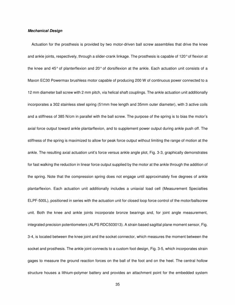
Mechanical Design
Actuation for the prosthesis is provided by two motor-driven ball screw assemblies that drive the knee
and ankle joints, respectively, through a slider-crank linkage. The prosthesis is capable of 120° of flexion at
the knee and 45° of planterflexion and 20° of dorsiflexion at the ankle. Each actuation unit consists of a
Maxon EC30 Powermax brushless motor capable of producing 200 W of continuous power connected to a
12 mm diameter ball screw with 2 mm pitch, via helical shaft couplings. The ankle actuation unit additionally
incorporates a 302 stainless steel spring (51mm free length and 35mm outer diameter), with 3 active coils
and a stiffness of 385 N/cm in parallel with the ball screw. The purpose of the spring is to bias the motor’s
axial force output toward ankle plantarflexion, and to supplement power output during ankle push off. The
stiffness of the spring is maximized to allow for peak force output without limiting the range of motion at the
ankle. The resulting axial actuation unit’s force versus ankle angle plot, Fig. 3-3, graphically demonstrates
for fast walking the reduction in linear force output supplied by the motor at the ankle through the addition of
the spring. Note that the compression spring does not engage until approximately five degrees of ankle
plantarflexion. Each actuation unit additionally includes a uniaxial load cell (Measurement Specialties
ELPF-500L), positioned in series with the actuation unit for closed loop force control of the motor/ballscrew
unit. Both the knee and ankle joints incorporate bronze bearings and, for joint angle measurement,
integrated precision potentiometers (ALPS RDC503013). A strain based sagittal plane moment sensor, Fig.
3-4, is located between the knee joint and the socket connector, which measures the moment between the
socket and prosthesis. The ankle joint connects to a custom foot design, Fig. 3-5, which incorporates strain
gages to measure the ground reaction forces on the ball of the foot and on the heel. The central hollow
structure houses a lithium-polymer battery and provides an attachment point for the embedded system
36
hardware. To better fit with an anthropomorphic envelope, the ankle joint is placed slightly anterior to the
centerline of the central structure. This gives the prosthesis the illusion of flexion when the amputee is
standing vertically with the knee fully extended.
Figure 3-3. The reduction of linear force output required by the ankle motor unit by the addition of a spring in
parallel for fast walking, taken from averaged normal biomechanical data [9].
Figure 3-4. Sagittal moment load cell, top and bottom views.
37
Figure 3-5. Sensorized prosthetic foot with and without strain gage covers.
The length of the shank segment is varied by changing the length of three components; the lower shank
extension, the spring pull-down, and the coupler between the ball nut and ankle. Additional adjustability is
provided by the pyramid connector that is integrated into the sagittal moment load cell for coupling the
prosthesis to the socket (as is standard in commercial transfemoral prostheses). The self-contained
transfemoral prosthesis was fabricated from 7075 aluminum and has a total mass of 4.2 kg, which is within
an acceptable range for transfemoral prostheses, and comparable to a normal limb segment [33]. A weight
breakdown of the device is presented in Table 3-2.
38
Table 3-2. Mass breakdown of self-contained powered prosthesis.
Component Mass (kg)
Battery 0.62
Electronics 0.36
Knee Motor Assembly 0.72
Ankle Motor Assembly 0.89
Sensorized Foot 0.35
Foot Shell 0.24
Sagittal Moment Sensor 0.12
Remaining Structure 0.90
Total Weight 4.20
Moment and Force Sensing
The sagittal plane moment between the user and prosthesis, and the force between the prosthesis and
ground is sensed in order to infer user intent and coordinate prosthesis control. Based on biomechanical
data [8, 9], the required range of measurements was determined to be 100 Nm of sagittal plane moment
and a ground reaction force of 1000 N. The sagittal plane moment is measured above the knee joint at the
socket interface and the ground reaction force is measured by the custom foot. The location of the sensors
was chosen to avoid coupling the desired measured ground reaction force and sagittal moment with the
joint torques. In addition, incorporating the ground reaction load cell into the structure of a custom foot
eliminates the added weight of a separate load cell, and also enables separate measurement of the heel
and ball of foot load.
The sagittal plane moment sensor, shown in Fig. 3-4, is designed to have a low profile in order to
accommodate longer residual limbs. The sensor incorporates a full bridge of semiconductor strain gages
which measure the strains generated by the sagittal plane moment. Finite element analysis, using
ProEngineer Mechanica, was used to minimize the overall design height and to achieve the desired strains
39
in the load cell. The sensor is fabricated from 7075 aluminum and has an assembled weight of 120 grams
including the stainless steel pyramid connector. The overall height of the sensor including the pyramid
connector is 32 mm, with a rectangular base of 78 mm by 44 mm. The device was calibrated for a
measurement range of 100 Nm, and exhibited linearity within ± 5% error over the full scale output.
The custom foot, shown in Fig. 3-5, was designed to measure the ground reaction force components at
the ball of the foot and heel. The foot is comprised of heel and toe beams, rigidly attached to a central fixture
and arranged as cantilever beams with an arch that allows for the load to be localized at the heel and ball of
the foot, respectively. Each heel and toe beam incorporates a full bridge of semiconductor strain gages that
measure the strains resulting from the respective ground contact forces. The foot utilized for the tests
described herein measures 220 mm long, 56 mm wide and is 35 mm tall to the top of the central fixture and
approximates a US size 12 or EU size 46 foot. The foot is fabricated from 7075 aluminum and weighs 350
grams. The dimensions and weight are similar to commercial low-profile carbon-fiber prosthetic feet, such
as the Otto Bock Lo-Rider. The prosthetic foot was designed to be housed in a soft prosthetic foot shell, as
shown in Fig. 3-2. The heel and ball of foot load sensors were calibrated for a measurement range of 1000
N, and demonstrated linearity within ± 4% error for the full scale output range.
Embedded System
The powered prosthesis contains an embedded microcontroller that allows for either tethered or
untethered operation. The embedded system consists of signal processing, power supply, power
electronics, communications and computation modules, Fig. 6. The system is powered by a lithium polymer
battery with 29.6 V nominal rating and 4000 mA-hr capacity. The signal electronics require ±12 V and +3.3
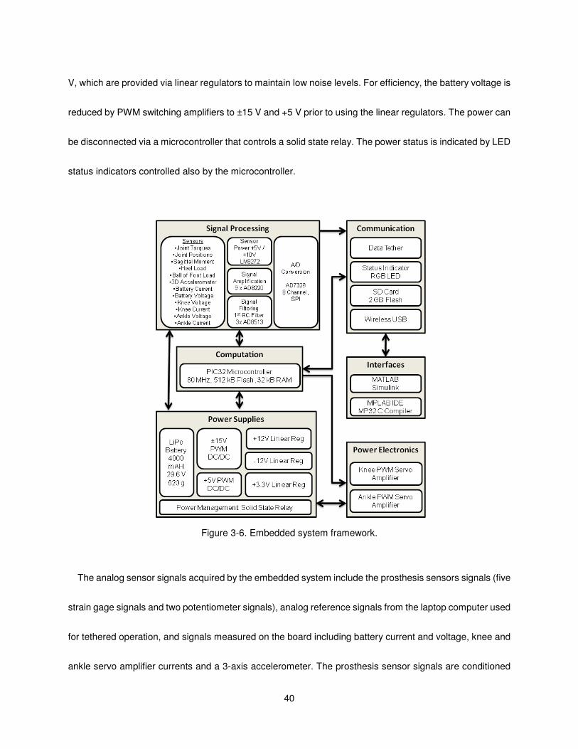
40
V, which are provided via linear regulators to maintain low noise levels. For efficiency, the battery voltage is
reduced by PWM switching amplifiers to ±15 V and +5 V prior to using the linear regulators. The power can
be disconnected via a microcontroller that controls a solid state relay. The power status is indicated by LED
status indicators controlled also by the microcontroller.
Figure 3-6. Embedded system framework.
The analog sensor signals acquired by the embedded system include the prosthesis sensors signals (five
strain gage signals and two potentiometer signals), analog reference signals from the laptop computer used
for tethered operation, and signals measured on the board including battery current and voltage, knee and
ankle servo amplifier currents and a 3-axis accelerometer. The prosthesis sensor signals are conditioned

41
using input instrumentation amplifiers (AD8220) over a range of +/-10 V. The battery, knee motor and ankle
motor currents are measured by current sensing across 0.02 Ohm resistors and via current sensing
amplifiers (LT1787HV). The signals are filtered with a first-order RC filter with 1.6 kHz cut off frequency for
the commercial load cells and joint angles and 160 Hz cutoff frequency for the sagittal moment, heel and
ball of foot custom load cells and buffered with high slew rate amplifiers before the analog to digital
conversion stage. Analog to digital conversion is accomplished by two 8-channel analog to digital
convertors (AD7329). The analog to digital conversion data is transferred to the microcontroller via serial
peripheral interface (SPI) bus.
The main computational element of the embedded system is an 80 MHz PIC32 microcontroller with 512
kB flash memory and 32 kB RAM, which consumes approximately 0.4 W of power. The microcontroller is
programmed in C using MPLAB IDE and MP32 C Compiler. In addition to untethered operation, the
prosthesis can also be controlled via a tether by a laptop computer running MATLAB Simulink RealTime
Workshop. In the untethered operation state, the microcontroller performs the servo and activity controllers
of the prosthesis and data logging at each sample time (1ms). In the tethered operation state, the
microcontroller drives the servo amplifiers based on analog reference signals from the laptop computer. A 1
GB SD memory card is used for logging time-stamped data acquired from the sensors and recording
internal controller information. The SD card is interfaced to the computer via wireless USB protocol. The
microcontroller sends PWM reference signals to two four quadrant brushless DC motor drivers (Advanced
Motion Control AZBDC20A8) rated at 12A continuous and 20A peak current output with regenerative
capabilities in the second and forth quadrants of the velocity/torque curve.
The embedded system printed circuit board is a 130 mm x 90 mm 4-layer board designed for surface
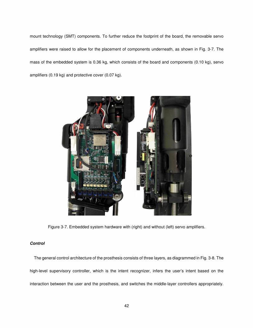
42
mount technology (SMT) components. To further reduce the footprint of the board, the removable servo
amplifiers were raised to allow for the placement of components underneath, as shown in Fig. 3-7. The
mass of the embedded system is 0.36 kg, which consists of the board and components (0.10 kg), servo
amplifiers (0.19 kg) and protective cover (0.07 kg).
Figure 3-7. Embedded system hardware with (right) and without (left) servo amplifiers.
Control
The general control architecture of the prosthesis consists of three layers, as diagrammed in Fig. 3-8. The
high-level supervisory controller, which is the intent recognizer, infers the user’s intent based on the
interaction between the user and the prosthesis, and switches the middle-layer controllers appropriately.
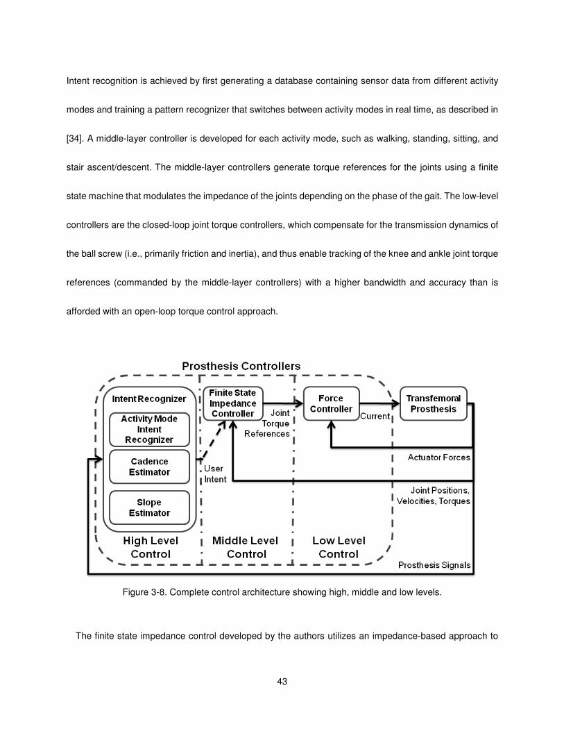
43
Intent recognition is achieved by first generating a database containing sensor data from different activity
modes and training a pattern recognizer that switches between activity modes in real time, as described in
[34]. A middle-layer controller is developed for each activity mode, such as walking, standing, sitting, and
stair ascent/descent. The middle-layer controllers generate torque references for the joints using a finite
state machine that modulates the impedance of the joints depending on the phase of the gait. The low-level
controllers are the closed-loop joint torque controllers, which compensate for the transmission dynamics of
the ball screw (i.e., primarily friction and inertia), and thus enable tracking of the knee and ankle joint torque
references (commanded by the middle-layer controllers) with a higher bandwidth and accuracy than is
afforded with an open-loop torque control approach.
Figure 3-8. Complete control architecture showing high, middle and low levels.
The finite state impedance control developed by the authors utilizes an impedance-based approach to
44
generate joint torques [26]. The joint torques for each activity mode, such as walking, standing, sitting, stair
ascent/descent, are governed by separate finite state machines, which modulate the joint impedance
according to the phase of gait. The finite state machines for walking and standing are diagrammed in Figs.
3-9 and 3-10, respectively. The state model for walking is described by five phases, three of which are
stance phases (early stance, middle stance, and late stance) and two of which are swing phases (swing
knee flexion and swing knee extension). The standing state model is described by two phases, which are a
weight bearing phase and a non-weight bearing phase. Note that the distinction between torque commands
and position commands is largely one of output impedance. That is, accurate tracking of position
trajectories requires a high joint output impedance, which is not characteristic of human gait. By generating
torques trajectories rather than position trajectories, the output impedance of each joint can be more closely
matched to the native limb, thus enabling the user to interact with the prosthesis by leveraging its dynamics
in a manner similar to normal gait. In other words, the resulting motion of each prosthesis joint is due to the
combination of the user input and the prosthesis input, rather than resulting from the prosthesis input alone
(as would be the case with a position-based controller). In each phase, the knee and ankle torques, τi , are
each described by a passive spring and damper with a fixed equilibrium point, given by:
θθθτ &ibkiiki +−= )(
(1)
where ki , bi , and θki denote the linear stiffness, damping coefficient, and equilibrium point, respectively,
for the ith state. Energy is delivered to the user by switching between appropriate equilibrium points (of the
virtual springs) during transitions between phases. In this manner, the prosthesis is guaranteed to be
passive within each phase, and thus generates power simply by switching between phases. Since the user
initiates phase switching, the result is a predictable controller that, barring phase switching input from the
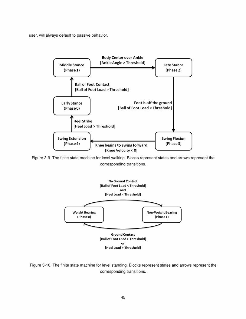
45
user, will always default to passive behavior.
Figure 3-9. The finite state machine for level walking. Blocks represent states and arrows represent the
corresponding transitions.
Figure 3-10. The finite state machine for level standing. Blocks represent states and arrows represent the
corresponding transitions.
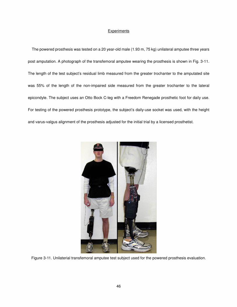
46
Experiments
The powered prosthesis was tested on a 20 year-old male (1.93 m, 75 kg) unilateral amputee three years
post amputation. A photograph of the transfemoral amputee wearing the prosthesis is shown in Fig. 3-11.
The length of the test subject’s residual limb measured from the greater trochanter to the amputated site
was 55% of the length of the non-impaired side measured from the greater trochanter to the lateral
epicondyle. The subject uses an Otto Bock C-leg with a Freedom Renegade prosthetic foot for daily use.
For testing of the powered prosthesis prototype, the subject’s daily-use socket was used, with the height
and varus-valgus alignment of the prosthesis adjusted for the initial trial by a licensed prosthetist.
Figure 3-11. Unilaterial transfemoral amputee test subject used for the powered prosthesis evaluation.

47
Parameter Tuning
Experiments were performed to characterize the knee and ankle joint angles, torques, and power while
walking over ground at a self-selected walking speed, and also to characterize the system’s electrical power
consumption, mechanical power generation, and efficiency. In order to conduct the over-ground
characterization, a series of experiments were required to parameterize the middle-layer controller to the
subject at various walking cadences. The controller parameterization was conducted on a treadmill at three
walking cadences. The nominal cadence used for parameter tuning was the subject’s self-selected
cadence while wearing his daily-use prosthesis. For over-ground walking, the subject walked comfortably
with his daily use (passive) prosthesis at 90 steps per minute at 4.1 km/h. For treadmill walking, the speed
indicator on the treadmill was covered and the subject adjusted the treadmill speed until he felt comfortable.
The self-selected normal cadence of the subject was determined to be 75 steps per minute at 2.8 km/h.
Fast and slow cadences were set at ±15 percent of the normal treadmill cadence resulting in treadmill
speeds of 2.2 and 3.4 km/h, respectively. The middle layer control parameters of the powered prosthesis
were then tuned (with the prosthesis controlled in the tethered state) while walking on the treadmill at slow,
normal and fast walking cadences (as determined by the daily use prosthesis), and also for standing.
During the standing mode, the test subject alternately shifted his weight between limbs, turned in place, and
stood still. Note that in all cases, the parameters were tuned using a combination of feedback from the user,
and from visual inspection of the joint angle, torque, and power data. Note also that the tethered operating
mode was utilized during treadmill parameter tuning because it enables quick and easy parameter variation
and data visualization, and thus greatly expedites the iterative parameter tuning process. The resulting
middle-layer controller parameters of the tuned impedance functions for standing and for the various
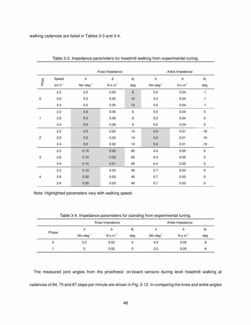
48
walking cadences are listed in Tables 3-3 and 3-4.
Table 3-3. Impedance parameters for treadmill walking from experimental tuning.
Knee Impedance Ankle Impedance
Phas
e Speed
km h-1
k
Nm deg-1
b
N s m-1
θk
deg
k
Nm deg-1
b
N s m-1
θk
deg
0
2.2 2.5 0.05 8 3.0 0.04 -1
2.8 2.5 0.05 10 3.0 0.04 -1
3.4 2.5 0.05 10 3.0 0.04 -1
1
2.2 4.0 0.06 6 5.0 0.04 0
2.8 5.0 0.06 6 5.0 0.04 0
3.4 5.0 0.06 6 5.0 0.04 0
2
2.2 3.0 0.02 14 4.0 0.01 -16
2.8 3.5 0.02 14 5.0 0.01 -16
3.4 5.0 0.02 14 5.0 0.01 -16
3
2.2 0.15 0.02 65 0.4 0.05 0
2.8 0.10 0.02 65 0.4 0.05 0
3.4 0.10 0.01 65 0.4 0.05 0
4
2.2 0.10 0.03 40 0.7 0.03 0
2.8 0.20 0.03 40 0.7 0.03 0
3.4 0.25 0.03 40 0.7 0.03 0
Note: Highlighted parameters vary with walking speed.
Table 3-4. Impedance parameters for standing from experimental tuning.
Knee Impedance Ankle Impedance
Phase k
Nm deg-1
b
N s m-1
θk
deg
k
Nm deg-1
b
N s m-1
θk
deg
0 2.5 0.02 0 4.0 0.05 -6
1 0 0.02 0 2.0 0.05 -6
The measured joint angles from the prosthesis’ on-board sensors during level treadmill walking at
cadences of 64, 75 and 87 steps per minute are shown in Fig. 3-12. In comparing the knee and ankle angles
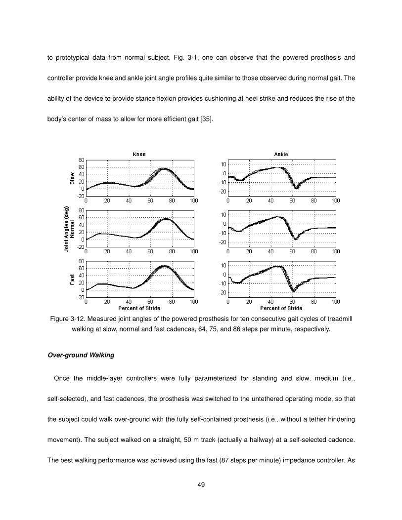
49
to prototypical data from normal subject, Fig. 3-1, one can observe that the powered prosthesis and
controller provide knee and ankle joint angle profiles quite similar to those observed during normal gait. The
ability of the device to provide stance flexion provides cushioning at heel strike and reduces the rise of the
body’s center of mass to allow for more efficient gait [35].
Figure 3-12. Measured joint angles of the powered prosthesis for ten consecutive gait cycles of treadmill
walking at slow, normal and fast cadences, 64, 75, and 86 steps per minute, respectively.
Over-ground Walking
Once the middle-layer controllers were fully parameterized for standing and slow, medium (i.e.,
self-selected), and fast cadences, the prosthesis was switched to the untethered operating mode, so that
the subject could walk over-ground with the fully self-contained prosthesis (i.e., without a tether hindering
movement). The subject walked on a straight, 50 m track (actually a hallway) at a self-selected cadence.
The best walking performance was achieved using the fast (87 steps per minute) impedance controller. As
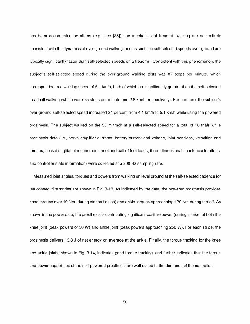
50
has been documented by others (e.g., see [36]), the mechanics of treadmill walking are not entirely
consistent with the dynamics of over-ground walking, and as such the self-selected speeds over-ground are
typically significantly faster than self-selected speeds on a treadmill. Consistent with this phenomenon, the
subject’s self-selected speed during the over-ground walking tests was 87 steps per minute, which
corresponded to a walking speed of 5.1 km/h, both of which are significantly greater than the self-selected
treadmill walking (which were 75 steps per minute and 2.8 km/h, respectively). Furthermore, the subject’s
over-ground self-selected speed increased 24 percent from 4.1 km/h to 5.1 km/h while using the powered
prosthesis. The subject walked on the 50 m track at a self-selected speed for a total of 10 trials while
prosthesis data (i.e., servo amplifier currents, battery current and voltage, joint positions, velocities and
torques, socket sagittal plane moment, heel and ball of foot loads, three dimensional shank accelerations,
and controller state information) were collected at a 200 Hz sampling rate.
Measured joint angles, torques and powers from walking on level ground at the self-selected cadence for
ten consecutive strides are shown in Fig. 3-13. As indicated by the data, the powered prosthesis provides
knee torques over 40 Nm (during stance flexion) and ankle torques approaching 120 Nm during toe-off. As
shown in the power data, the prosthesis is contributing significant positive power (during stance) at both the
knee joint (peak powers of 50 W) and ankle joint (peak powers approaching 250 W). For each stride, the
prosthesis delivers 13.8 J of net energy on average at the ankle. Finally, the torque tracking for the knee
and ankle joints, shown in Fig. 3-14, indicates good torque tracking, and further indicates that the torque
and power capabilities of the self-powered prosthesis are well-suited to the demands of the controller.
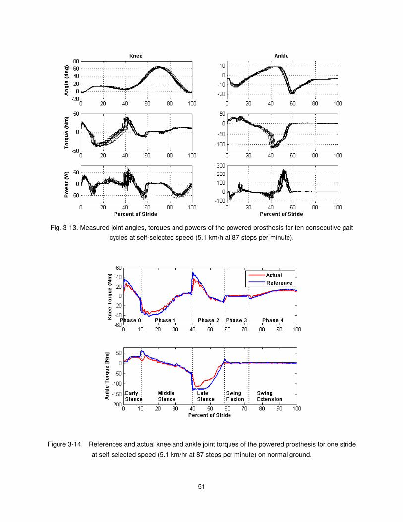
51
Fig. 3-13. Measured joint angles, torques and powers of the powered prosthesis for ten consecutive gait
cycles at self-selected speed (5.1 km/h at 87 steps per minute).
Figure 3-14. References and actual knee and ankle joint torques of the powered prosthesis for one stride
at self-selected speed (5.1 km/hr at 87 steps per minute) on normal ground.

52
Power Consumption and Battery Life
One of the primary constraints of the electrically powered knee and ankle prosthesis design is the power
source. As such, the electrical power consumption was measured to characterize the potential battery life
and range of the device. The electrical power consumed (at the motor leads) and the mechanical power
generated over one gait cycle are shown in Fig. 3-15. Electrical power regeneration (afforded by the
regenerative servo amplifiers) is observed in the late swing gait phase in the knee. It is interesting to note
that the peak electrical power event for level walking at the knee joint occurs at heel strike. At the ankle joint,
a peak mechanical power output of over 200W is experienced at toe-off, which requires approximately 50
percent more electrical power at the motor leads.
Figure 3-15. Measured electrical and mechanical power at the knee and ankle joints of the powered
prosthesis over one gait cycle at self-selected speed (5.1 km/hr at 87 steps per minute) on normal ground.
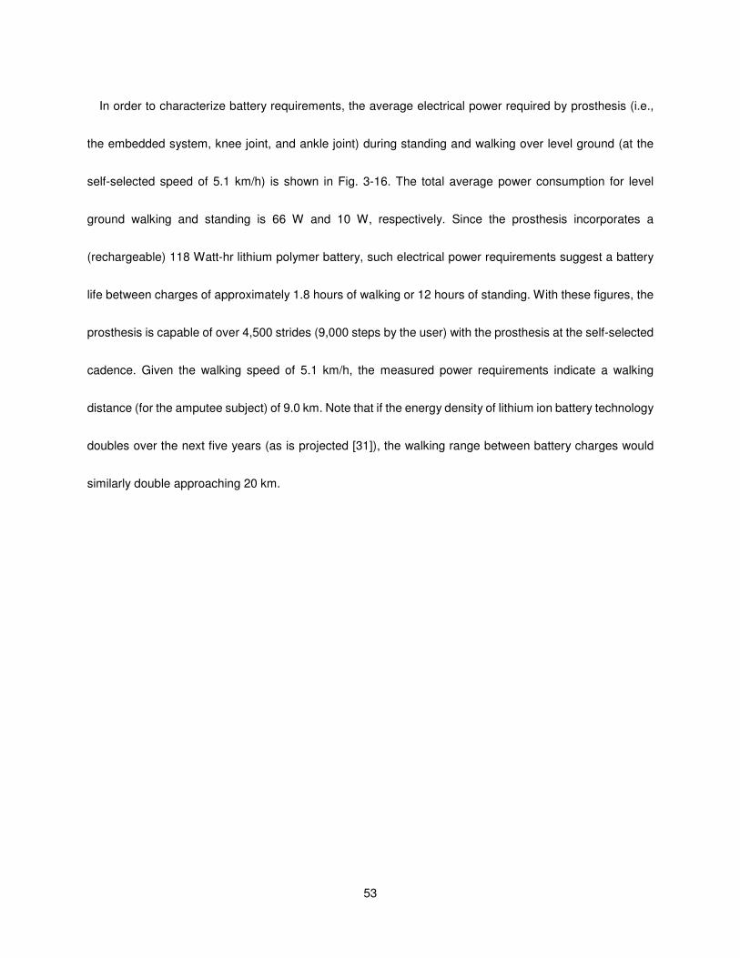
53
In order to characterize battery requirements, the average electrical power required by prosthesis (i.e.,
the embedded system, knee joint, and ankle joint) during standing and walking over level ground (at the
self-selected speed of 5.1 km/h) is shown in Fig. 3-16. The total average power consumption for level
ground walking and standing is 66 W and 10 W, respectively. Since the prosthesis incorporates a
(rechargeable) 118 Watt-hr lithium polymer battery, such electrical power requirements suggest a battery
life between charges of approximately 1.8 hours of walking or 12 hours of standing. With these figures, the
prosthesis is capable of over 4,500 strides (9,000 steps by the user) with the prosthesis at the self-selected
cadence. Given the walking speed of 5.1 km/h, the measured power requirements indicate a walking
distance (for the amputee subject) of 9.0 km. Note that if the energy density of lithium ion battery technology
doubles over the next five years (as is projected [31]), the walking range between battery charges would
similarly double approaching 20 km.
54
Figure 3-16. Average electrical power consumption of the powered prosthesis for standing and walking at
self-selected speed (5.1 km/hr at 87 steps per minute) on normal ground.
Conclusion
The paper describes the design and control of a fully self-contained electrically powered knee and ankle
prosthesis capable of producing human-scale power. Experimental results with a unilateral amputee
indicate that the device can provide transfemoral amputee biomechanics during walking similar to those
typically observed during healthy biomechanics. Power consumption measurements on level ground
indicate that device consumes 66 W at a walking speed of 5.1 km/h on a 75 kg subject. As such, given the
specifications of the on-board battery pack, the prosthesis can provide 9.0 km of level, over-ground walking
between recharges. Future works include addressing the audible noise of the device and a comprehensive
biomechanical evaluation of the powered prosthesis on multiple amputee subjects.

55
References
[1] P. F. Adams, G. E. Hendershot, and M. A. Marano, “Current estimates from the National Health
Interview Survey, 1996,” National Center for Health Statistics. Vital Health Stat 10(200), 1999.
[2] J. Feinglass, J. L. Brown, A. LaSasso, M. W. Sohn, L. M. Manheim, S. J. Shah, and W. H. Pearce,
“Rates of lower-extremity amputation and arterial reconstruction in the United States, 1979 to
1996,” American J. of Public Health, vol. 89, no. 8, pp. 1222-1227, Aug, 1999.
[3] P. DeVita, M. Torry, K. L. Glover, and D. L. Speroni, “A functional knee brace alters joint torque and
power patterns during walking and running,” J. of Biomechanics, vol. 29, no. 5, pp. 583-588, May,
1996.
[4] R. Jacobs, M. F. Bobbert, and G. J. van Ingen Schenau, “Mechanical output from individual
muscles during explosive leg extensions: The role of biarticular muscles,” J. of Biomechanics, vol.
29, no. 4, pp. 513-523, Apr, 1996.
[5] S. Nadeau, B. J. McFadyen, and F. Malouin, “Frontal and sagittal plane analyses of the stair
climbing task in healthy adults aged over 40 years: what are the challenges compared to level
walking?,” Clinical Biomechanics, vol. 18, no. 10, pp. 950-959, Dec, 2003.
[6] A. Nagano, Y. Ishige, and S. Fukashiro, “Comparison of new approaches to estimate mechanical
output of individual joints in vertical jumps,” J. of Biomechanics, vol. 31, no. 10, pp. 951-955, Oct,
1998.
[7] B. I. Prilutsky, L. N. Petrova, and L. M. Raitsin, “Comparison of mechanical energy expenditure of
joint moments and muscle forces during human locomotion,” J. of Biomechanics, vol. 29, no. 4, pp.
405-415, Apr, 1996.
[8] R. Riener, M. Rabuffetti, and C. Frigo, “Joint powers in stair climbing at different slopes,” Proc. of
the First Joint BMES/EMBS Conf., vol. 1, pp. 530 vol.1, 1999.
[9] D. Winter, The Biomechanics and Motor Control of Human Gait: Normal, Elderly and Pathological,
2nd ed.: University of Waterloo Press, 1991.
[10] D. A. Winter, and S. E. Sienko, “Biomechanics of below-knee amputee gait,” J. of Biomechanics,
vol. 21, no. 5, pp. 361-367, 1988.
[11] R. L. Waters, J. Perry, D. Antonelli, and H. Hislop, “Energy cost of walking of amputees - Influence
of level of amputation,” J. of Bone and Joint Surgery-American Vol., vol. 58, no. 1, pp. 42-46, 1976.
[12] M. Donath, “Proportional EMG control for above knee prostheses,” Massachusetts Institute of
Tech. Dept. of Mechanical Eng. Thesis. M.S., 1974.

56
[13] W. C. Flowers, “A man-interactive simulator system for above-knee prosthetics studies,”
Massachusetts Institute of Tech. Dept. of Mechanical Eng. Thesis. Ph.D., 1973.
[14] W. C. Flowers, and R. W. Mann, “Electrohydraulic knee-torque controller for a prosthesis
simulator,” ASME J. of Biomechanical Engineering, vol. 99, no. 4, pp. 3-8, 1977.
[15] D. L. Grimes, “An active multi-mode above knee prosthesis controller,” Massachusetts Institute of
Tech. Dept. of Mechanical Eng. Thesis Ph.D., 1979.
[16] D. L. Grimes, W. C. Flowers, and M. Donath, “Feasibility of an active control scheme for above
knee prostheses,” ASME J. of Biomechanical Engineering, vol. 99, no. 4, pp. 215-221, 1977.
[17] J. L. Stein, and W. C. Flowers, “Stance phase-control of above-knee prostheses - Knee control
versus SACH foot design,” J. of Biomechanics, vol. 20, no. 1, pp. 19-28, 1987.
[18] J. L. Stein, and Massachusetts Institute of Technology. Dept. of Mechanical Engineering., “Design
issues in the stance phase control of above-knee prostheses,” Massachusetts Institute of Tech.
Dept. of Mechanical Eng. Thesis Ph.D., 1983.
[19] D. Popovic, and L. Schwirtlich, “Belgrade active A/K prosthesis,” in de Vries, J. (Ed.),
Electrophysiological Kinesiology, Intern. Congress Ser. No. 804, Excerpta Medica, Amsterdam,
The Netherlands, pp. 337-343, 1988.
[20] S. Bedard, and P. Roy, Actuated leg prosthesis for above-knee amputees, 7,314,490, U. S. Patent,
June 17, 2003.
[21] E. Martinez- Villalpando, J. Weber, G. Elliott, and H. Herr, “Design of an agonist-antagonist active
knee prosthesis,” Proc. IEEE/RAS-EMBS Int. Conf. on Biomedical Robotics and Biomechatronics,
pp. 529-534, 2008.
[22] G. K. Klute, J. Czerniecki, and B. Hannaford, “Muscle-like pneumatic actuators for below-knee
prostheses,” Proc. 7th Int. Conf. on New Actuators, pp. 289-292, 2000.
[23] W. Koniuk, Self-adusting prosthetic ankle apparatus, 6,443,993, U. S. Patent, March, 23, 2001.
[24] R. Bellman, A. Holgate, and T. Sugar, “SPARKy 3: Design of an active robotic ankle prosthesis
with two actuated degrees of freedom using regenerative kinetics,” Proc. IEEE/RAS-EMBS Int.
Conf. on Biomedical Robotics and Biomechatronics, pp. 511-516, 2008.
[25] S. Au, and H. Herr, “Powered ankle-foot prosthesis,” IEEE Robotics & Automation Magazine, vol.
15, pp. 52-59, 2008.
[26] F. Sup, A. Bohara, and M. Goldfarb, “Design and control of a powered transfemoral prosthesis,” Int.
J. of Robotics Research, vol. 27, no. 2, pp. 263-273, Feb, 2008.

57
[27] K. B. Fite, and M. Goldfarb, “Design and energetic characterization of a proportional-injector
monopropellant-powered actuator,” IEEE/ASME Trans. on Mechatronics, vol. 11, no. 2, pp.
196-204, Apr, 2006.
[28] K. B. Fite, J. E. Mitchell, E. J. Barth, and M. Goldfarb, “A unified force controller for a
proportional-injector direct-injection monopropellant-powered actuator,” J. of Dynamic Systems
Measurement and Control Trans. of ASME, vol. 128, no. 1, pp. 159-164, Mar, 2006.
[29] M. Goldfarb, E. J. Barth, M. A. Gogola, and J. A. Wehrmeyer, “Design and energetic
characterization of a liquid-propellant-powered actuator for self-powered robots,” IEEE/ASME
Trans. on Mechatronics, vol. 8, no. 2, pp. 254-262, 2003.
[30] B. L. Shields, K. B. Fite, and M. Goldfarb, “Design, control, and energetic characterization of a
solenoid-injected monopropellant-powered actuator,” IEEE/ASME Trans. on Mechatronics, vol. 11,
no. 4, pp. 477-487, Aug, 2006.
[31] “In search of the perfect battery,” Economist, vol. 386, no. 8570, pp. 22-24, 2008.
[32] F. Sup, H. A. Varol, J. Mitchell, T. Withrow, and M. Goldfarb, “Design and control of an active
electrical knee and ankle prosthesis,” Proc. IEEE/RAS-EMBS Int. Conf. on Biomedical Robotics
and Biomechatronics, pp. 523-528, 2008.
[33] C. E. Clauser, J. T. McConville, and J. M. Young, “Weight, volume and center of mass of segments
of the human body,” AMRL-TR-69-70, Wright Patterson Airforce Base, Dayton, Ohio, 1969.
[34] H. A. Varol, F. Sup, and M. Goldfarb, “Real-time gait mode intent recognition of a powered knee
and ankle prosthesis for standing and walking,” Proc. IEEE/RAS-EMBS Int. Conf. on Biomedical
Robotics and Biomechatronics, pp. 66-72, 2008.
[35] S. Blumentritt, H. Scherer, U. Wellershaus, and J. Michael, “Design principles, biomechanical data
and clinical experience with a polycentric knee offering controlled stance phase knee flexion: A
preliminary report,” J. of Prosthetics and Orthotics, vol. 9, no. 1, pp. 18-24, 1997.
[36] M. Traballesi, P. Porcacchia, T. Averna, and S. Brunelli, “Energy cost of walking measurements in
subjects with lower limb amputations: A comparison study between floor and treadmill test,” Gait &
Posture, vol. 27, no. 1, pp. 70-75, Jan, 2008.

58
CHAPTER IV
Manuscript 3: Powered Sit-to-Stand and Assistive Stand-to-Sit Framework For a
Powered Transfemoral Prosthesis
Huseyin Atakan Varol, Frank Sup and Michael Goldfarb
Vanderbilt University
Nashville, TN 37235
Accepted as a Technical Paper to the
2009 IEEE International Conference on Rehabilitation Robotics
59
Abstract
This work extends the three level powered knee and ankle prosthesis control framework previously
developed by the authors by adding sitting mode. A middle level finite state based impedance controller is
designed to accommodate sitting, sit-to-stand and stand-to-sit transitions. Moreover, a high level Gaussian
Mixture Model based intent recognizer is developed to distinguish between standing and sitting modes and
switch the middle level controllers accordingly. Experimental results with unilateral transfemoral amputee
subject show that sitting down and standing up intent can be inferred from the prosthesis sensor signals by
the intent recognizer. Furthermore, it is demonstrated that the prosthesis generates net active power of 50
W during standing up and dissipates up to 50 W of power during stand-to-sit transition at the knee joint.
Introduction
Standing up is a frequently exercised daily activity which involves the coordinated movement of the entire
body to substantially raise the body center of mass in a generally economical manner. It requires significant
torque and range of motion at the knee joint and to a lesser extent the ankle joint [1-5]. Fundamentally, the
ability to stand up from a seated position is a prerequisite to begin walking and extend one’s mobility. In
general, transfemoral amputees with prostheses that lack active power can have difficulty standing up or
are unable to without aid, thus, predisposing them to a sedentary lifestyle. For a transfemoral amputee to
accomplish the sit-to-stand transition unaided, requires twice the torque output from the sound side knee
joint as compared to heFaalthy subjects [6] and additionally requires significantly increased compensatory
torques in the frontal plane. Furthermore, the amputee does not bear weight on the prosthesis until they are

60
almost in the standing position [6]. To compensate for the lack of power in the lower limb, amputees often
rely on the aid of their upper limbs and handrails. Conversely, passive prostheses are more assistive while
sitting down. They enable the user to bear weight on both sides reducing excessive torques on the sound
side joint. State-of-the-art microcontroller modulated braking knees adjust the damping on the knee joint to
control the resistance during stand to sit transition [7]. However, an active prosthesis would benefit the user
during stand-to-sit transition by providing active power to recover to the standing position in case the user
changes his or her intent to sit down. The quality of life and mobility of transfemoral amputees could benefit
from active assistance provided by a prosthesis with powered joints during the standing up (SU) and sitting
down (SD) transitions.
The design of powered transfemoral prostheses is a challenging task due to the large range of motion on
the knee joint and the magnitude of the power and torques that need to be applied at both the knee and
ankle. Development of powered transfemoral prostheses dates back to the early 1970’s with a tethered
electro-hydraulically actuated knee joint. This prosthesis was a test bed for studying the feasibility of
powered knee joints during walking [8]. Other prior work was conducted on the development of an active
knee joint actuated by electrical motors with finite state position controller [9]. Ossur, a prosthetics
company, introduced a powered knee prosthesis that is capable of generating net active power [10]. An
agonist-antagonist knee design which utilizes the passive dynamics of the knee during walking is presented
in [11]. The authors were not able to find any scientific literature on SU and SD transitions for these active
transfemoral prostheses.
A self-contained powered knee and ankle prosthesis has been developed by the authors which aims to
restore normal locomotive function to transfemoral amputees. The authors have also explored a three level
61
control architecture consisting of a high level intent recognizer, a middle level finite state based impedance
controller and low level force-controller for walking and standing. In this work, the control architecture will be
expanded to include sitting and the associated SU and SD transitions. The paper is designed as follows.
Firstly, the powered prosthesis used in this study is presented. Secondly, the finite state based impedance
controller for standing, sitting, and SU and SD transitions is described. Thirdly, the design of the intent
recognizer for the sitting mode is described. Finally, experimental results with a unilateral transfemoral
amputee are presented and discussed.
Methodology
Powered Prosthesis
The authors have previously described a tethered powered knee and ankle prosthesis [12]. A new
(previously unreported) self-contained version of the prosthesis, shown in Fig. 4-1, was used for the
powered sit-to-stand and assistive stand-to-sit testing, described herein. The powered prosthesis is a two
degree of freedom robotic device capable of generating human-scale torque and power at the knee and
ankle joints. Actuation of each joint is accomplished via slider-crank linkages driven by motor ball screw
assemblies. The ankle actuation unit incorporates a spring to bias the motor’s axial force output toward
ankle plantarflexion, and to supplement power output during ankle push off. The device's sensor package
includes a custom load cell to measure the sagittal socket interface moment above the knee joint, a custom
foot to measure the ground reaction force at the heel and ball of the foot, and commercial potentiometers
and load cells to measure joint positions and torques, respectively. The self-contained version hosts an
embedded system allowing for both tethered and untethered operation run by either MATLAB Simulink or a
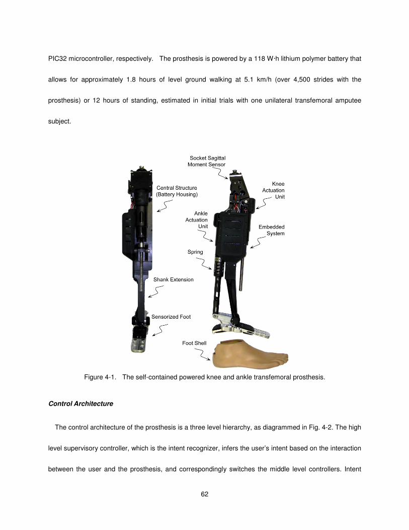
62
PIC32 microcontroller, respectively. The prosthesis is powered by a 118 W·h lithium polymer battery that
allows for approximately 1.8 hours of level ground walking at 5.1 km/h (over 4,500 strides with the
prosthesis) or 12 hours of standing, estimated in initial trials with one unilateral transfemoral amputee
subject.
Figure 4-1. The self-contained powered knee and ankle transfemoral prosthesis.
Control Architecture
The control architecture of the prosthesis is a three level hierarchy, as diagrammed in Fig. 4-2. The high
level supervisory controller, which is the intent recognizer, infers the user’s intent based on the interaction
between the user and the prosthesis, and correspondingly switches the middle level controllers. Intent
63
recognition is achieved by first generating a database containing sensor data from different activity modes
and then training a pattern recognizer that switches between activity modes in real time, as described in
[13]. A middle level controller is developed for each activity mode, such as walking, standing, sitting, and
stair ascent/descent. The middle level controllers generate torque references for the joints using a finite
state machine that modulates the impedance of the joints depending on the phase of the activity. The
low-level controllers are the closed-loop joint torque controllers, which compensate for the transmission
dynamics of the ball screw (i.e., primarily friction and inertia), and thus enable tracking of the knee and ankle
joint torque references (commanded by the middle level controllers) with a higher bandwidth and accuracy
than is afforded with an open-loop torque control approach. In this work, the design of the supervisory intent
recognizer and the finite state impedance based controller for the sitting and standing modes will be
presented.
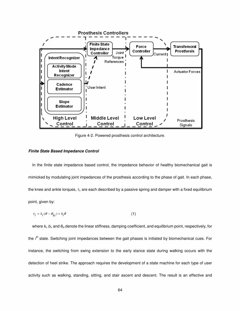
64
Figure 4-2. Powered prosthesis control architecture.
Finite State Based Impedance Control
In the finite state impedance based control, the impedance behavior of healthy biomechanical gait is
mimicked by modulating joint impedances of the prosthesis according to the phase of gait. In each phase,
the knee and ankle torques, τi, are each described by a passive spring and damper with a fixed equilibrium
point, given by:
θθθτ &ibkiiki +−= )( (1)
where ki, bi, and θki denote the linear stiffness, damping coefficient, and equilibrium point, respectively, for
the ith state. Switching joint impedances between the gait phases is initiated by biomechanical cues. For
instance, the switching from swing extension to the early stance state during walking occurs with the
detection of heel strike. The approach requires the development of a state machine for each type of user
activity such as walking, standing, sitting, and stair ascent and descent. The result is an effective and
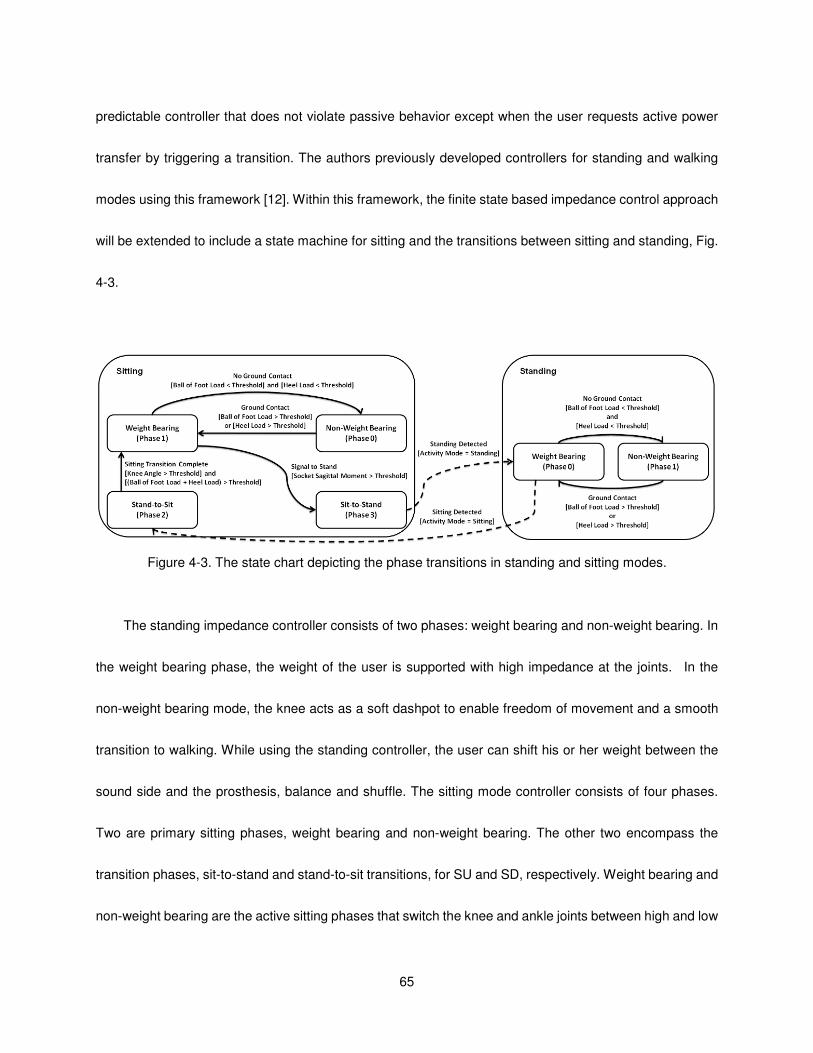
65
predictable controller that does not violate passive behavior except when the user requests active power
transfer by triggering a transition. The authors previously developed controllers for standing and walking
modes using this framework [12]. Within this framework, the finite state based impedance control approach
will be extended to include a state machine for sitting and the transitions between sitting and standing, Fig.
4-3.
Figure 4-3. The state chart depicting the phase transitions in standing and sitting modes.
The standing impedance controller consists of two phases: weight bearing and non-weight bearing. In
the weight bearing phase, the weight of the user is supported with high impedance at the joints. In the
non-weight bearing mode, the knee acts as a soft dashpot to enable freedom of movement and a smooth
transition to walking. While using the standing controller, the user can shift his or her weight between the
sound side and the prosthesis, balance and shuffle. The sitting mode controller consists of four phases.
Two are primary sitting phases, weight bearing and non-weight bearing. The other two encompass the
transition phases, sit-to-stand and stand-to-sit transitions, for SU and SD, respectively. Weight bearing and
non-weight bearing are the active sitting phases that switch the knee and ankle joints between high and low
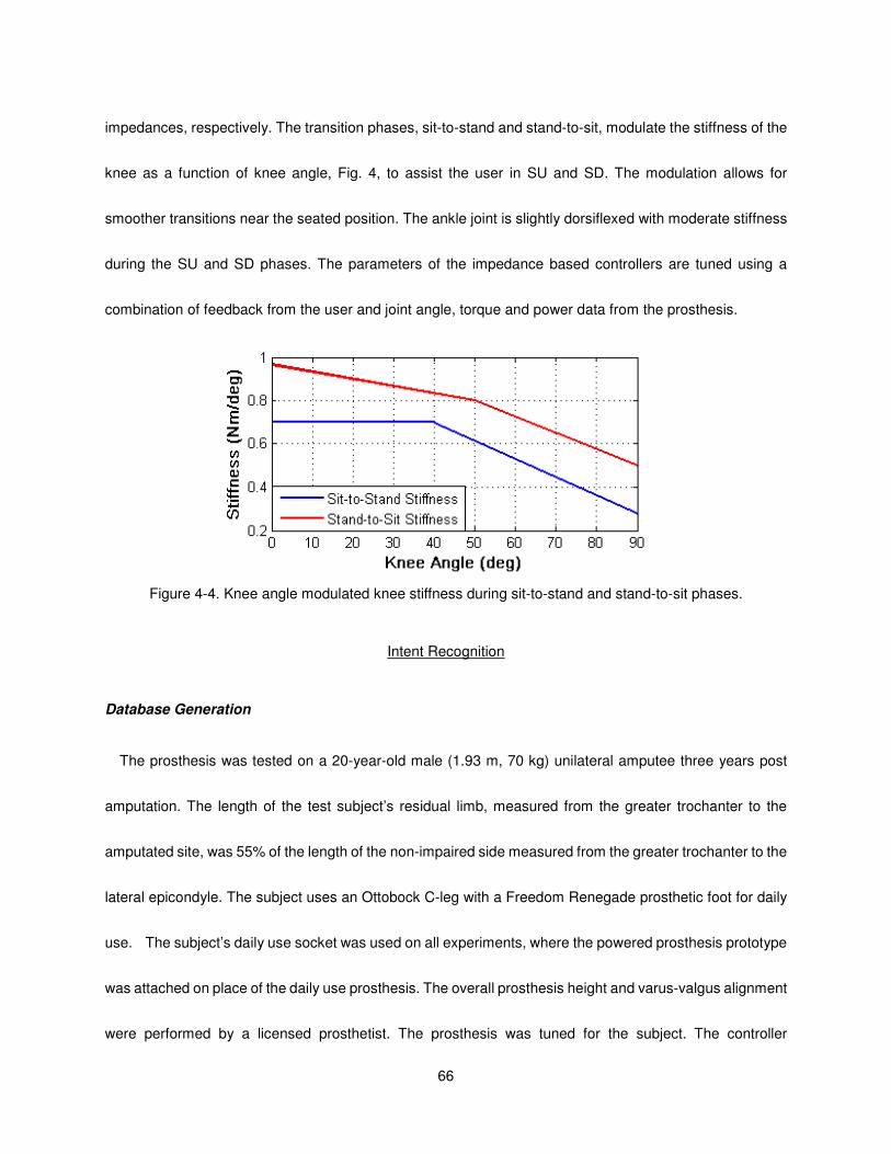
66
impedances, respectively. The transition phases, sit-to-stand and stand-to-sit, modulate the stiffness of the
knee as a function of knee angle, Fig. 4, to assist the user in SU and SD. The modulation allows for
smoother transitions near the seated position. The ankle joint is slightly dorsiflexed with moderate stiffness
during the SU and SD phases. The parameters of the impedance based controllers are tuned using a
combination of feedback from the user and joint angle, torque and power data from the prosthesis.
Figure 4-4. Knee angle modulated knee stiffness during sit-to-stand and stand-to-sit phases.
Intent Recognition
Database Generation
The prosthesis was tested on a 20-year-old male (1.93 m, 70 kg) unilateral amputee three years post
amputation. The length of the test subject’s residual limb, measured from the greater trochanter to the
amputated site, was 55% of the length of the non-impaired side measured from the greater trochanter to the
lateral epicondyle. The subject uses an Ottobock C-leg with a Freedom Renegade prosthetic foot for daily
use. The subject’s daily use socket was used on all experiments, where the powered prosthesis prototype
was attached on place of the daily use prosthesis. The overall prosthesis height and varus-valgus alignment
were performed by a licensed prosthetist. The prosthesis was tuned for the subject. The controller
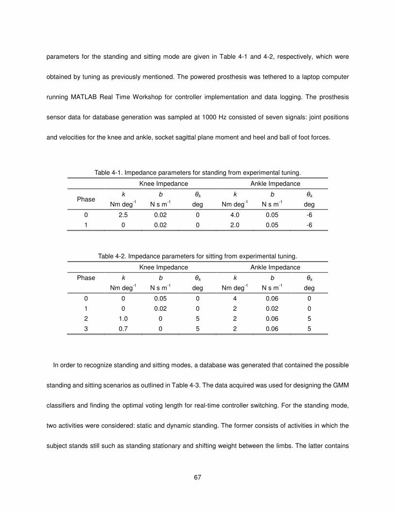
67
parameters for the standing and sitting mode are given in Table 4-1 and 4-2, respectively, which were
obtained by tuning as previously mentioned. The powered prosthesis was tethered to a laptop computer
running MATLAB Real Time Workshop for controller implementation and data logging. The prosthesis
sensor data for database generation was sampled at 1000 Hz consisted of seven signals: joint positions
and velocities for the knee and ankle, socket sagittal plane moment and heel and ball of foot forces.
Table 4-1. Impedance parameters for standing from experimental tuning.
Knee Impedance Ankle Impedance
Phase k
Nm deg-1
b
N s m-1
θk
deg
k
Nm deg-1
b
N s m-1
θk
deg
0 2.5 0.02 0 4.0 0.05 -6
1 0 0.02 0 2.0 0.05 -6
Table 4-2. Impedance parameters for sitting from experimental tuning.
Knee Impedance Ankle Impedance
Phase k
Nm deg-1
b
N s m-1
θk
deg
k
Nm deg-1
b
N s m-1
θk
deg
0 0 0.05 0 4 0.06 0
1 0 0.02 0 2 0.02 0
2 1.0 0 5 2 0.06 5
3 0.7 0 5 2 0.06 5
In order to recognize standing and sitting modes, a database was generated that contained the possible
standing and sitting scenarios as outlined in Table 4-3. The data acquired was used for designing the GMM
classifiers and finding the optimal voting length for real-time controller switching. For the standing mode,
two activities were considered: static and dynamic standing. The former consists of activities in which the
subject stands still such as standing stationary and shifting weight between the limbs. The latter contains
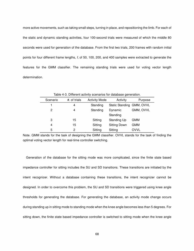
68
more active movements, such as taking small steps, turning in place, and repositioning the limb. For each of
the static and dynamic standing activities, four 100-second trials were measured of which the middle 80
seconds were used for generation of the database. From the first two trials, 200 frames with random initial
points for four different frame lengths, f, of 50, 100, 200, and 400 samples were extracted to generate the
features for the GMM classifier. The remaining standing trials were used for voting vector length
determination.
Table 4-3. Different activity scenarios for database generation.
Scenario #. of trials Activity Mode Activity Purpose
1 4 Standing Static Standing GMM, OVVL
2 4 Standing Dynamic
Standing
GMM, OVVL
3 15 Sitting Standing Up GMM
4 15 Sitting Sitting Down GMM
5 2 Sitting Sitting OVVL
Note. GMM stands for the task of designing the GMM classifier. OVVL stands for the task of finding the
optimal voting vector length for real-time controller switching.
Generation of the database for the sitting mode was more complicated, since the finite state based
impedance controller for sitting includes the SU and SD transitions. These transitions are initiated by the
intent recognizer. Without a database containing these transitions, the intent recognizer cannot be
designed. In order to overcome this problem, the SU and SD transitions were triggered using knee angle
thresholds for generating the database. For generating the database, an activity mode change occurs
during standing up in sitting mode to standing mode when the knee angle becomes less than 5 degrees. For
sitting down, the finite state based impedance controller is switched to sitting mode when the knee angle
69
exceeds 5 degrees. Fifteen trials for both cases are conducted. The four seconds after the sitting down
transition and four seconds before the SU transition are recorded for generating the feature frames for the
GMM classifier design. From each trial 20 frames of length 50, 100, 200 and 400 samples are generated.
Moreover, two 100-second sitting trials were recorded for finding the optimal voting vector length for sitting
to standing transitions. During these trials, the subject sat on a stool, did sitting activities such as
repositioning limbs, changing orientation, and reaching an object excluding SU transition. For each frame
length, the database for the GMM classifier design included 800 frames of standing data and 600 frames of
sitting data.
Feature Extraction
The real-time nature of the problem requires that the features extracted from the seven prosthesis signals
be computationally inexpensive, and as such, the mean and standard deviation were selected as features
to extract from each frame, resulting in 14 fundamental simple time domain features. After the features were
extracted, they were normalized into the range of [-1, 1] to eliminate the scaling effects between different
features. Balancing the information content of a frame against frame length is important since additional
delay for intent recognition is introduced as the frame size grows. In order to find the optimal frame length,
different frame sizes (50, 100, 200 and 400 samples) were considered.
Dimension Reduction
In order to decrease the time required for real-time intent recognition and training and prevent over-fitting,
the feature space was reduced (at the cost of information content) using Principal Component Analysis
(PCA) [14] and Linear Discriminant Analysis (LDA) [15], from 14 dimensions to a feature space of 1, 2
70
and 3 dimensions. Both approaches employ linear transformations, which only necessitate a matrix
multiplication operation. Since orthonormal transformations tend to decrease the magnitude of the
elements in the transformed matrix as compared to the initial matrix, the reduced features are normalized
into the range of [-1, 1] to avoid any possible numerical instability in the GMM classification phase.
Gaussian Mixture Model Activity Mode Classification
Gaussian Mixture Models (GMM) are used to characterize the probability that the user and prosthesis is
engaged in a given activity mode. Specifically, a separate GMM is used to describe each activity mode, wi.
For some set of inputs xr
, the probability of being in an activity mode, wi, is given by:
∑=
=K
k
i
k
i
ki xpwxp1
)()|(rr
λ (1)
where
−∑′−−∑
= −)()()(
2
1exp
)2(
1)(
1 i
k
i
k
i
ki
k
D
i
k xxxp µµπ
rrrrr (2)
where K is the number of components of the mixture model, i
kλ is the mixture parameter of the ith GMM
for the kth component, which satisfy the constraints 1
1=∑ =
K
k
i
kλ and 0≥ikλ . The mixture component, )(xp i
k
r,
is a multivariate Gaussian probability density function with a 1×D mean vector, i
kµr
, and DD × full
covariance matrix, i
k∑ , with 2/)1( +DD free parameters. Each GMM can be parameterized by
1)2/)1(1( −+++ DDDK parameters, which are the mixture parameters, mean vectors and covariance
matrices, notated as },,{ i
k
i
k
i
kiw ∑= µλr
. Once the GMM’s are parameterized, for a given sample feature
vector, Sxr
, the activity mode, wm, is selected as the mode with the highest probability:
))|((maxarg iSw
m wxpwi
r= . (3)
Parameterization of the GMM’s for all desired activity modes is achieved based on training data in an

71
iterative fashion with the Expectation Maximization (EM) algorithm [16]. Several initialization schemes for
EM are suggested in [17]. In this work, the reduced dataset for an activity mode, wi, is roughly clustered
using the k-means algorithm [18]. These clusters are used to initialize the EM algorithm for finding the
mixtures. A key factor affecting the classification performance of GMM’s is the number of mixture
components, K. As such, the performance of the models for a range of mixture components should be
considered and compared for a given application.
Model Selection
The model search space consists of 42 models, which in turn consist of 6 dimension methods (i.e., PCA
and LDA for 1 to 3 dimensions) applied to 7 GMM models ranging from order 2 to 8, for each frame length.
In order to find the best classifier for each frame length, the Area under the Receiver Operator
Characteristics curve (AUC) [19] is used as the performance metric. The reason for choosing AUC is
twofold. Firstly, it provides a comprehensive metric that computes true and false positives for all possible
classification thresholds observed in the data. Secondly, the AUC metric is insensitive to class distribution.
10-fold cross-validation (CV) [20] is employed to avoid over-fitting. In 10-fold CV, the data is split into 10
sets of size 10/N . For purposes of model selection, the classifier is trained on 9 datasets and tested for the
AUC on the remaining one. This is repeated ten times until all the data splits are tested and the mean AUC
score is recorded as the performance metric of a specific classifier.
Voting Scheme for Controller Mode Switching
The activity mode intent recognizer is a component of the supervisory controller for the powered
prosthesis and has two performance objectives. The first objective is to switch to another mode in the
72
shortest time possible when a mode transition occurs, and the second objective is to avoid switching to
another mode when there is no real transition. With respect to the first objective, a longer switching time will
decrease the quality of movements since the user will have a perceived latency of the assistance from the
prosthesis. However, failure to meet the second objective could have more severe consequences (i.e.
causing loss of balance and even a fall). Therefore, to increase assurance of correct mode switching, a
voting scheme is used.
In the real-time implementation, overlapping frames are classified at each 10 ms interval ( t∆ ). In the
voting scheme, the last l classifier decisions are stored in a voting vector and mode switching occurs if more
than 90 percent of the classification results are in agreement. To avoid chattering during transition and
increase the robustness of the powered prosthesis control, a rule was introduced to not allow the controller
mode to switch for 500 ms after a mode switching occurs.
The combination of the voting length, l, and the frame length, f, determines the delay of activity mode
intent recognition. To optimize the voting vector length, l, the last two trials for each scenario in the
experimental database were used. In this process, the real-time activity intent recognizer is implemented
offline with possible voting vector length from 10 to 100 in increments of 10. For a specific frame length, f,
the smallest voting length, ls, which does not switch to standing for the sitting trials and to standing for sitting
trials, is selected as the optimal voting vector length.
Once the optimal voting length for each frame is found, the best frame length for the real-time activity
intent mode recognition needs to be determined. It is assumed that the two trials for each scenario
encompass all the possible cases and the best models for each frame length are reliable, meaning they do
not result in incorrect controller switching. Hence, the problem becomes to select the frame length which
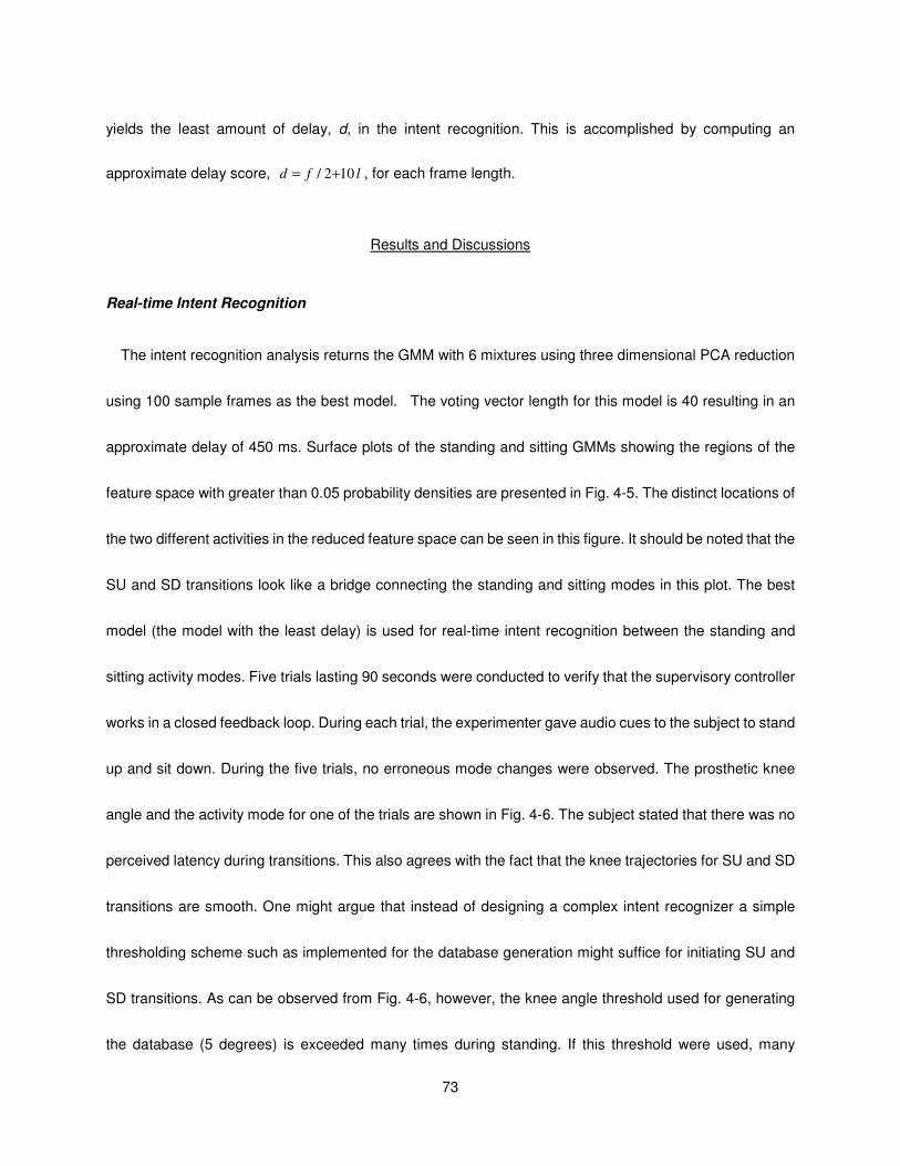
73
yields the least amount of delay, d, in the intent recognition. This is accomplished by computing an
approximate delay score, lfd 102/ += , for each frame length.
Results and Discussions
Real-time Intent Recognition
The intent recognition analysis returns the GMM with 6 mixtures using three dimensional PCA reduction
using 100 sample frames as the best model. The voting vector length for this model is 40 resulting in an
approximate delay of 450 ms. Surface plots of the standing and sitting GMMs showing the regions of the
feature space with greater than 0.05 probability densities are presented in Fig. 4-5. The distinct locations of
the two different activities in the reduced feature space can be seen in this figure. It should be noted that the
SU and SD transitions look like a bridge connecting the standing and sitting modes in this plot. The best
model (the model with the least delay) is used for real-time intent recognition between the standing and
sitting activity modes. Five trials lasting 90 seconds were conducted to verify that the supervisory controller
works in a closed feedback loop. During each trial, the experimenter gave audio cues to the subject to stand
up and sit down. During the five trials, no erroneous mode changes were observed. The prosthetic knee
angle and the activity mode for one of the trials are shown in Fig. 4-6. The subject stated that there was no
perceived latency during transitions. This also agrees with the fact that the knee trajectories for SU and SD
transitions are smooth. One might argue that instead of designing a complex intent recognizer a simple
thresholding scheme such as implemented for the database generation might suffice for initiating SU and
SD transitions. As can be observed from Fig. 4-6, however, the knee angle threshold used for generating
the database (5 degrees) is exceeded many times during standing. If this threshold were used, many
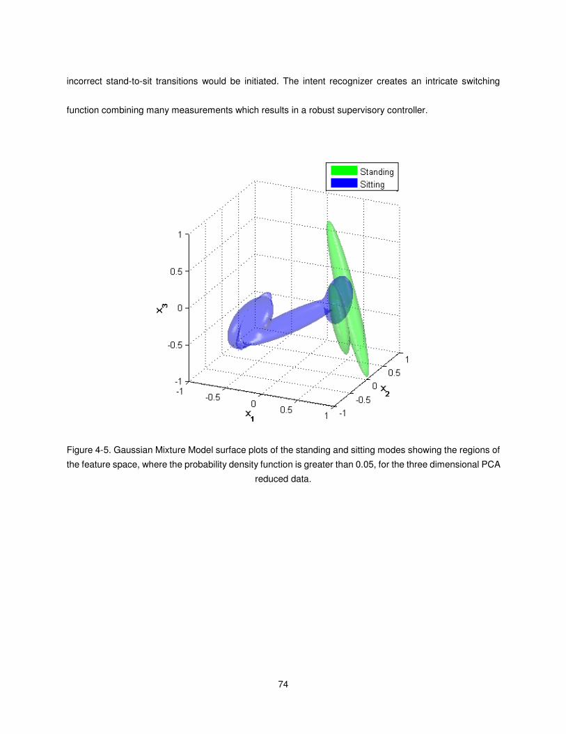
74
incorrect stand-to-sit transitions would be initiated. The intent recognizer creates an intricate switching
function combining many measurements which results in a robust supervisory controller.
Figure 4-5. Gaussian Mixture Model surface plots of the standing and sitting modes showing the regions of
the feature space, where the probability density function is greater than 0.05, for the three dimensional PCA
reduced data.
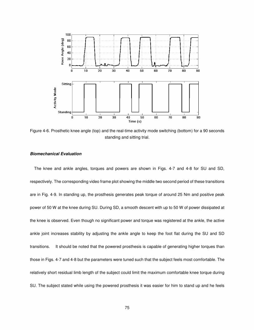
75
Figure 4-6. Prosthetic knee angle (top) and the real-time activity mode switching (bottom) for a 90 seconds
standing and sitting trial.
Biomechanical Evaluation
The knee and ankle angles, torques and powers are shown in Figs. 4-7 and 4-8 for SU and SD,
respectively. The corresponding video frame plot showing the middle two second period of these transitions
are in Fig. 4-9. In standing up, the prosthesis generates peak torque of around 25 Nm and positive peak
power of 50 W at the knee during SU. During SD, a smooth descent with up to 50 W of power dissipated at
the knee is observed. Even though no significant power and torque was registered at the ankle, the active
ankle joint increases stability by adjusting the ankle angle to keep the foot flat during the SU and SD
transitions. It should be noted that the powered prosthesis is capable of generating higher torques than
those in Figs. 4-7 and 4-8 but the parameters were tuned such that the subject feels most comfortable. The
relatively short residual limb length of the subject could limit the maximum comfortable knee torque during
SU. The subject stated while using the powered prosthesis it was easier for him to stand up and he feels
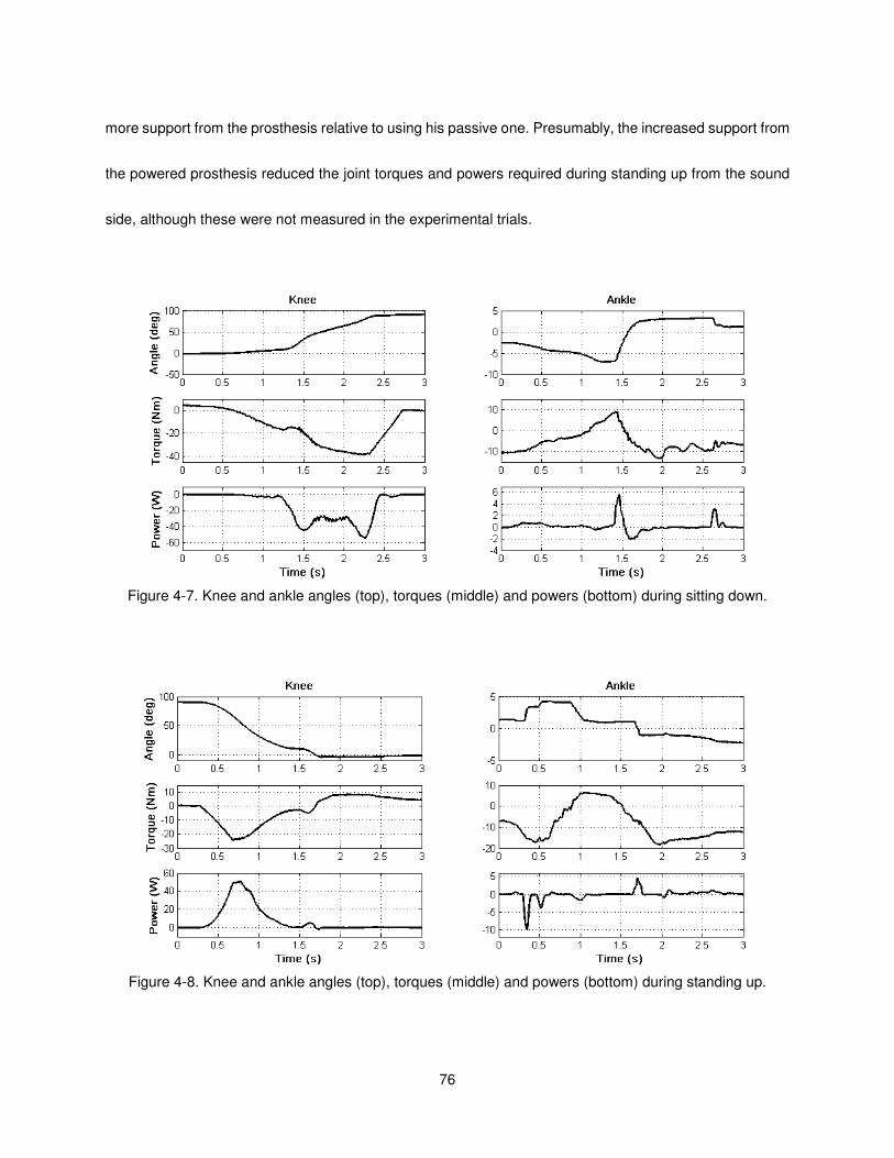
76
more support from the prosthesis relative to using his passive one. Presumably, the increased support from
the powered prosthesis reduced the joint torques and powers required during standing up from the sound
side, although these were not measured in the experimental trials.
Figure 4-7. Knee and ankle angles (top), torques (middle) and powers (bottom) during sitting down.
Figure 4-8. Knee and ankle angles (top), torques (middle) and powers (bottom) during standing up.
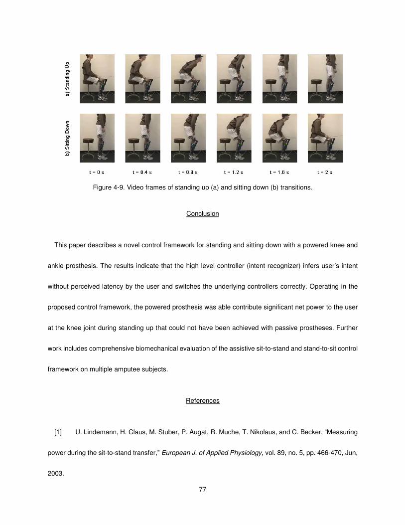
77
Figure 4-9. Video frames of standing up (a) and sitting down (b) transitions.
Conclusion
This paper describes a novel control framework for standing and sitting down with a powered knee and
ankle prosthesis. The results indicate that the high level controller (intent recognizer) infers user’s intent
without perceived latency by the user and switches the underlying controllers correctly. Operating in the
proposed control framework, the powered prosthesis was able contribute significant net power to the user
at the knee joint during standing up that could not have been achieved with passive prostheses. Further
work includes comprehensive biomechanical evaluation of the assistive sit-to-stand and stand-to-sit control
framework on multiple amputee subjects.
References
[1] U. Lindemann, H. Claus, M. Stuber, P. Augat, R. Muche, T. Nikolaus, and C. Becker, “Measuring
power during the sit-to-stand transfer,” European J. of Applied Physiology, vol. 89, no. 5, pp. 466-470, Jun,
2003.

78
[2] M. Galli, V. Cimolin, M. Crivellini, and I. Campanini, “Quantitative analysis of sit to stand
movement: Experimental set-up definition and application to healthy and hemiplegic adults,” Gait &
Posture, vol. 28, no. 1, pp. 80-85, Jul, 2008.
[3] A. Kralj, R. J. Jaeger, and M. Munih, “Analysis of Standing up and Sitting down in Humans -
Definitions and Normative Data Presentation,” J. of Biomechanics, vol. 23, no. 11, pp. 1123-1138, 1990.
[4] W. G. M. Janssen, H. B. J. Bussmann, and H. J. Stam, “Determinants of the sit-to-stand
movement: A review,” Physical Therapy, vol. 82, no. 9, pp. 866-879, Sep, 2002.
[5] M. Schenkman, R. A. Berger, P. O. Riley, R. W. Mann, and W. A. Hodge, “Whole-body
movements during rising to standing from sitting,” Physical Therapy, vol. 70, no. 10, pp. 638-648, Oct, 1990.
[6] H. Burger, J. Kuzelicki, and C. Marincek, “Transition from sitting to standing after trans-femoral
amputation,” Prosthetics and Orthotics International, vol. 29, no. 2, pp. 139-151, Aug, 2005.
[7] D. Berry, “Microprocessor prosthetic knees,” Phys Med Rehabil Clin N Am, vol. 17, no. 1, pp.
91-113, vii, Feb, 2006.
[8] W. C. Flowers, and R. W. Mann, “Electrohydraulic knee-torque controller for a prosthesis
simulator,” ASME J. of Biomechanical Engineering, vol. 99, no. 4, pp. 3-8, 1977.
[9] D. Popovic, and L. Schwirtlich, “Belgrade active A/K prosthesis,” in de Vries, J. (Ed.),
Electrophysiological Kinesiology, Intern. Congress Ser. No. 804, Excerpta Medica, Amsterdam, The
Netherlands, pp. 337-343, 1988.
[10] S. Bedard, and P. Roy, Actuated Leg Prosthesis for Above-Knee Amputees, U. S. Patent, 2003.
[11] E. Martinez- Villalpando, J. Weber, G. Elliott, and H. Herr, “Design of an agonist-antagonist active
knee prosthesis,” Proc. IEEE/RAS-EMBS Int. Conf. on Biomedical Robotics and Biomechatronics, pp.

79
529-534, 2008.
[12] F. Sup, H. A. Varol, J. Mitchell, T. Withrow, and M. Goldfarb, “Design and control of an active
electrical knee and ankle prosthesis,” Proc. IEEE/RAS-EMBS Int. Conf. on Biomedical Robotics and
Biomechatronics, pp. 523-528, 2008.
[13] H. A. Varol, F. Sup, and M. Goldfarb, “Real-time gait mode intent recognition of a powered knee
and ankle prosthesis for standing and walking,” Proc. IEEE/RAS-EMBS Int. Conf. on Biomedical Robotics
and Biomechatronics, pp. 66-72, 2008.
[14] I. T. Jolliffe, Principal Component Analysis, 2nd ed., New York: Springer, 2002.
[15] R. A. Fisher, “The statistical utilization of multiple measurements,” Annals of Eugenics, vol. 8, pp.
376-386, 1938.
[16] A. P. Dempster, N. M. Laird, and D. B. Rubin, “Maximum likelihood from incomplete data via EM
algorithm,” J. of the Royal Statistical Society Series B-Methodological, vol. 39, no. 1, pp. 1-38, 1977.
[17] G. J. McLachlan, and D. Peel, Finite mixture models, New York: Wiley, 2000.
[18] J. A. Hartigan, and M. A. Wong, “A K-means clustering algorithm,” Applied Statistics, vol. 28, no.
1, pp. 100-108, 1979.
[19] T. Fawcett, “An Introduction to ROC Analysis,” Pattern Recognition Letters, vol. 27, no. 8, pp.
861-874, Jun, 2006.
[20] T. M. Mitchell, Machine Learning, New York: McGraw-Hill, 1997.

80
CHAPTER V
Slope Ascent with a Powered Knee and Ankle Prosthesis
Note: The work presented in this chapter will be combined with the supervisory controller for cadence and
slope estimators and submitted to IEEE Transactions on Neural Systems and Rehabilitation Engineering.
Abstract
This paper extends the functionality of a powered knee and ankle prosthesis previously developed by the
authors by incorporating a slope ascent controller to the control architecture. The powered prosthesis
employs a finite-state impedance control framework to coordinate user prosthesis interaction. Results with
a unilateral transfemoral amputee demonstrate that near normal gait on slopes of 5 and 10 degrees can be
achieved with the proposed control and powered prosthesis. Increases in knee flexion and ankle
dorsiflexion during stance are observed relative to level walking. Power consumption measurements
indicate the device consumes 45, 60 and 72 W for level, 5, and 10 degrees upslope walking.
Introduction
In daily living, walking on inclined surfaces is a frequently encountered activity which requires significant
coordination and power in the lower limbs. With respect to kinematics, upslope walking necessitates an
increased range of motion at the hip, knee and ankle joints as compared to level ground walking [1]. The
maximum moments and powers observed at the knee and hip joints correlate closely with increasing slope
angle [2]. This trend is also observed at the ankle to a lesser extent [2]. Furthermore, there is an upward
trend in metabolic cost of transport corresponding with steeper grades of inclines [3].
81
Presently, most commercial lower limb prostheses are passive devices and are unable to deliver net
power. This loss of net power generation at the lower limb impairs the ability of the prosthesis to restore
biomechanically normal level, walking up stairs and slopes, and rising from the seated position [4-10]. In the
absence of net power generation at the knee and ankle, transfemoral amputees with passive prostheses
have been shown to expend 60% more metabolic energy [10] and exert three times the affected-side hip
power and torque [5] when compared to healthy subjects during level walking. When walking on inclines,
transfemoral amputees cannot achieve knee flexion in the prosthetic knee and must compensate by
altering their gait patterns [4]. Since inclined walking is more demanding in regards to the kinetics and
energy expenditure compared to level walking [3], the difficulties faced by amputee in upslope walking will
be exacerbated. Presumably, introduction of power to lower limb prostheses might alleviate the difficulties
confronted by amputees while walking up slopes.
Active prosthesis development aimed to return mobility and functionality to amputees dates back to the
early 1970’s with a tethered electro-hydraulically actuated knee joint. This prosthesis served as a test bed
for studying the feasibility of powered knee joints during walking [11]. More recently, Ossur, a prosthetics
company, introduced a powered knee prosthesis that is capable of generating net active power. The device
provides stance assistance for stair and slope ascent and a powered swing [12]. Work in powered
transtibial prostheses includes the “Proprio Foot” developed by Ossur, the “powered” ankle prosthesis does
not contribute net power to gait, but rather adjusts the ankle angle to accommodate ground slope during
swing. While sitting, the device adjusts the ankle angle to better accommodate sitting posture [13]. Bellman
et al. describe an active robotic ankle prosthesis with actuated degrees of freedom in both the sagittal and
frontal planes [14]. Au and Herr built a powered ankle-foot prosthesis that incorporates both parallel and

82
series elasticity to reduce peak motor torque and power requirements and to provide a more suitable output
impedance [15]. The authors were not able to find any scientific literature on slope ascent for any of these
active lower limb prostheses.
The authors have previously developed a powered knee and ankle prosthesis with the primary goal of
restoring normal locomotive functions to transfemoral amputees [16]. This work demonstrated the potential
of such a device to restore near normal gait patterns and increase self-selected walking speed of a
transfemoral amputee on level ground relative to a daily-use passive prosthesis. The device has been
successfully demonstrated in walking, standing, sitting and sit-to-stand and stand-to-sit transitions [16-18].
Within the previously developed control framework, the present work demonstrates the extension of the
walking controller to inclined slopes. The paper is organized as follows. Firstly, the control framework for the
powered prosthesis is detailed. Secondly, the extension of the control to accommodate slope ascent is
explained. Thirdly, an overview of the powered prosthesis used in this study and the experimental protocol
is presented. Lastly, biomechanical results with a transfemoral amputee walking upslope over ground are
reported and discussed.
Methodology
Control Architecture
The powered prosthesis operates with a three level control hierarchy, as diagrammed in Fig. 5-1. The
high level supervisory controller, which is the intent recognizer, infers the user’s intent based on the
interaction between the user and the prosthesis, and correspondingly switches the middle level controllers,
as described in [17, 18]. Additionally, the high level controller estimates ground slope with an accelerometer
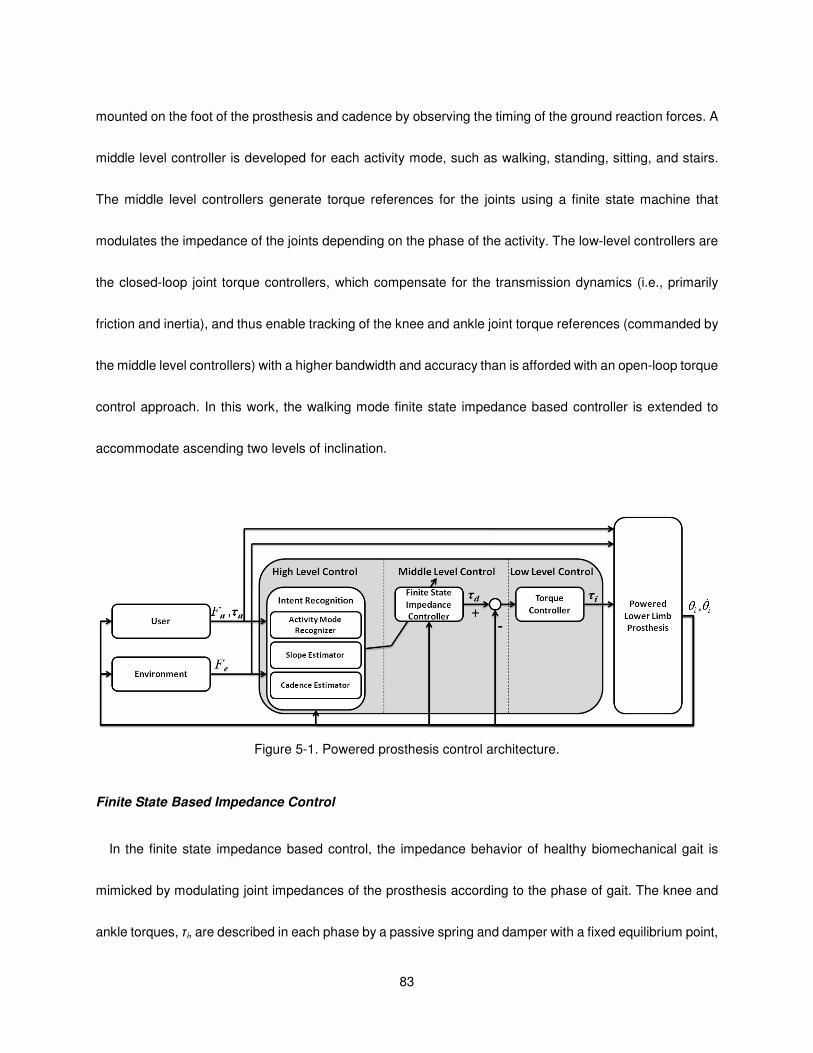
83
mounted on the foot of the prosthesis and cadence by observing the timing of the ground reaction forces. A
middle level controller is developed for each activity mode, such as walking, standing, sitting, and stairs.
The middle level controllers generate torque references for the joints using a finite state machine that
modulates the impedance of the joints depending on the phase of the activity. The low-level controllers are
the closed-loop joint torque controllers, which compensate for the transmission dynamics (i.e., primarily
friction and inertia), and thus enable tracking of the knee and ankle joint torque references (commanded by
the middle level controllers) with a higher bandwidth and accuracy than is afforded with an open-loop torque
control approach. In this work, the walking mode finite state impedance based controller is extended to
accommodate ascending two levels of inclination.
Figure 5-1. Powered prosthesis control architecture.
Finite State Based Impedance Control
In the finite state impedance based control, the impedance behavior of healthy biomechanical gait is
mimicked by modulating joint impedances of the prosthesis according to the phase of gait. The knee and
ankle torques, τi, are described in each phase by a passive spring and damper with a fixed equilibrium point,
84
given by:
θθθτ &ibkiiki +−= )( (1)
where ki, bi, and θki denote the linear stiffness, damping coefficient, and equilibrium point, respectively, for
the ith state. Switching joint impedances between the gait phases is initiated by biomechanical cues, such
as heel strike or the changing from knee flexion to extension during swing. The approach requires the
development of a state machine for each type of user activity such as walking, standing, sitting, and stair
ascent and descent. In particular, the state model for walking, Fig. 5-2, is described by five phases, three of
which are stance phases (early stance, middle stance, and late stance) and two of which are swing phases
(swing knee flexion and swing knee extension). The result is an effective and predictable controller that
does not violate passive behavior except when the user requests active power transfer by triggering a
transition. The authors previously developed controllers for standing, level walking for different speeds, and
sitting [16-18].
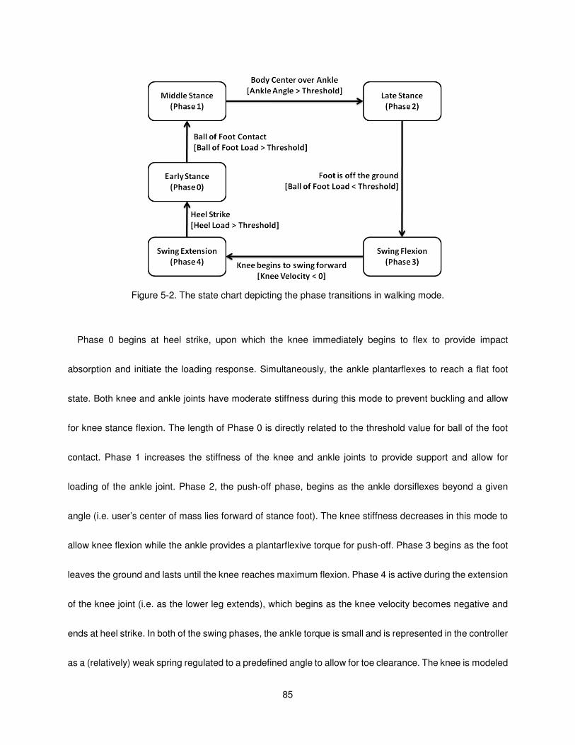
85
Figure 5-2. The state chart depicting the phase transitions in walking mode.
Phase 0 begins at heel strike, upon which the knee immediately begins to flex to provide impact
absorption and initiate the loading response. Simultaneously, the ankle plantarflexes to reach a flat foot
state. Both knee and ankle joints have moderate stiffness during this mode to prevent buckling and allow
for knee stance flexion. The length of Phase 0 is directly related to the threshold value for ball of the foot
contact. Phase 1 increases the stiffness of the knee and ankle joints to provide support and allow for
loading of the ankle joint. Phase 2, the push-off phase, begins as the ankle dorsiflexes beyond a given
angle (i.e. user’s center of mass lies forward of stance foot). The knee stiffness decreases in this mode to
allow knee flexion while the ankle provides a plantarflexive torque for push-off. Phase 3 begins as the foot
leaves the ground and lasts until the knee reaches maximum flexion. Phase 4 is active during the extension
of the knee joint (i.e. as the lower leg extends), which begins as the knee velocity becomes negative and
ends at heel strike. In both of the swing phases, the ankle torque is small and is represented in the controller
as a (relatively) weak spring regulated to a predefined angle to allow for toe clearance. The knee is modeled
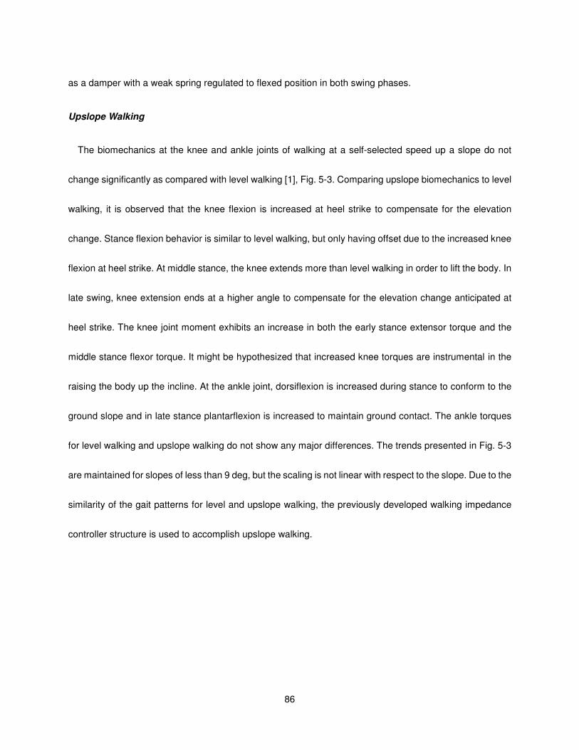
86
as a damper with a weak spring regulated to flexed position in both swing phases.
Upslope Walking
The biomechanics at the knee and ankle joints of walking at a self-selected speed up a slope do not
change significantly as compared with level walking [1], Fig. 5-3. Comparing upslope biomechanics to level
walking, it is observed that the knee flexion is increased at heel strike to compensate for the elevation
change. Stance flexion behavior is similar to level walking, but only having offset due to the increased knee
flexion at heel strike. At middle stance, the knee extends more than level walking in order to lift the body. In
late swing, knee extension ends at a higher angle to compensate for the elevation change anticipated at
heel strike. The knee joint moment exhibits an increase in both the early stance extensor torque and the
middle stance flexor torque. It might be hypothesized that increased knee torques are instrumental in the
raising the body up the incline. At the ankle joint, dorsiflexion is increased during stance to conform to the
ground slope and in late stance plantarflexion is increased to maintain ground contact. The ankle torques
for level walking and upslope walking do not show any major differences. The trends presented in Fig. 5-3
are maintained for slopes of less than 9 deg, but the scaling is not linear with respect to the slope. Due to the
similarity of the gait patterns for level and upslope walking, the previously developed walking impedance
controller structure is used to accomplish upslope walking.
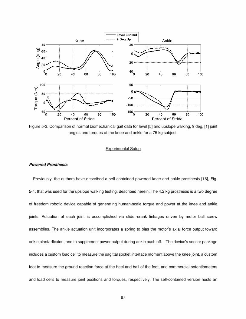
87
Figure 5-3. Comparison of normal biomechanical gait data for level [5] and upslope walking, 9 deg, [1] joint
angles and torques at the knee and ankle for a 75 kg subject.
Experimental Setup
Powered Prosthesis
Previously, the authors have described a self-contained powered knee and ankle prosthesis [16], Fig.
5-4, that was used for the upslope walking testing, described herein. The 4.2 kg prosthesis is a two degree
of freedom robotic device capable of generating human-scale torque and power at the knee and ankle
joints. Actuation of each joint is accomplished via slider-crank linkages driven by motor ball screw
assemblies. The ankle actuation unit incorporates a spring to bias the motor’s axial force output toward
ankle plantarflexion, and to supplement power output during ankle push off. The device's sensor package
includes a custom load cell to measure the sagittal socket interface moment above the knee joint, a custom
foot to measure the ground reaction force at the heel and ball of the foot, and commercial potentiometers
and load cells to measure joint positions and torques, respectively. The self-contained version hosts an
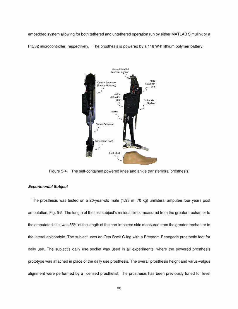
88
embedded system allowing for both tethered and untethered operation run by either MATLAB Simulink or a
PIC32 microcontroller, respectively. The prosthesis is powered by a 118 W·h lithium polymer battery.
Figure 5-4. The self-contained powered knee and ankle transfemoral prosthesis.
Experimental Subject
The prosthesis was tested on a 20-year-old male (1.93 m, 70 kg) unilateral amputee four years post
amputation, Fig. 5-5. The length of the test subject’s residual limb, measured from the greater trochanter to
the amputated site, was 55% of the length of the non-impaired side measured from the greater trochanter to
the lateral epicondyle. The subject uses an Otto Bock C-leg with a Freedom Renegade prosthetic foot for
daily use. The subject’s daily use socket was used in all experiments, where the powered prosthesis
prototype was attached in place of the daily use prosthesis. The overall prosthesis height and varus-valgus
alignment were performed by a licensed prosthetist. The prosthesis has been previously tuned for level
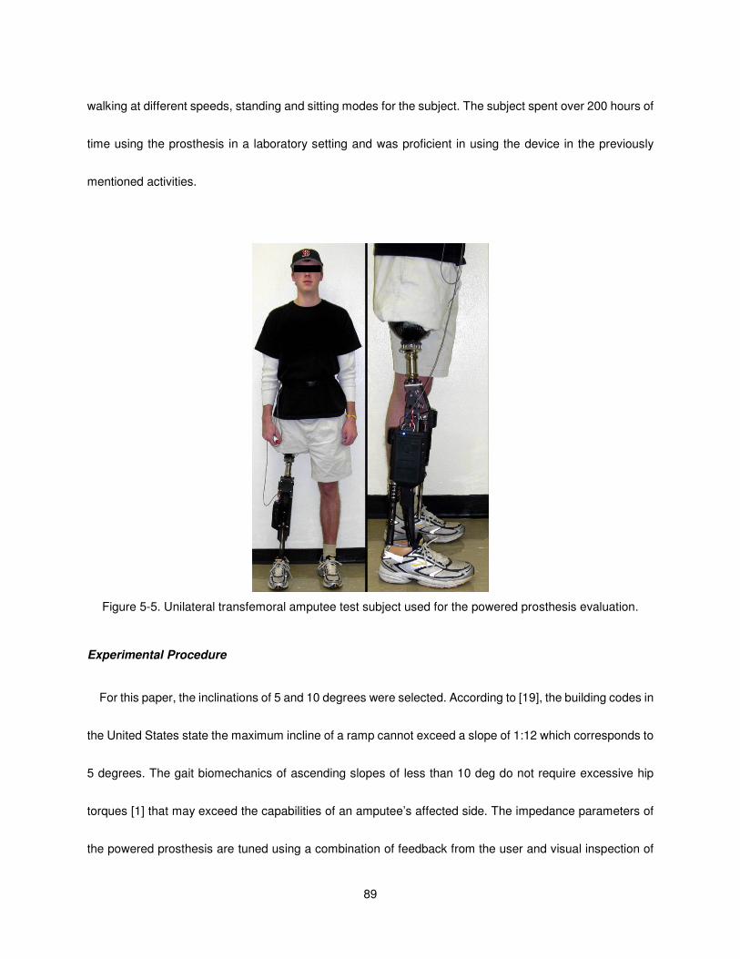
89
walking at different speeds, standing and sitting modes for the subject. The subject spent over 200 hours of
time using the prosthesis in a laboratory setting and was proficient in using the device in the previously
mentioned activities.
Figure 5-5. Unilateral transfemoral amputee test subject used for the powered prosthesis evaluation.
Experimental Procedure
For this paper, the inclinations of 5 and 10 degrees were selected. According to [19], the building codes in
the United States state the maximum incline of a ramp cannot exceed a slope of 1:12 which corresponds to
5 degrees. The gait biomechanics of ascending slopes of less than 10 deg do not require excessive hip
torques [1] that may exceed the capabilities of an amputee’s affected side. The impedance parameters of
the powered prosthesis are tuned using a combination of feedback from the user and visual inspection of
90
the joint angle, torque, and power data. First, the prosthesis was tuned for self-selected speed level ground
walking. In this tuning process, two objectives were considered. The first objective was to achieve healthy
biomechanical gait patterns as shown in level walking data presented in [5]. The second objective was to
decrease the effort based on the qualitative feedback from the subject. Starting with the level ground
parameters, the prosthesis was tuned for the subject for 5 deg upslope walking in an iterative manner. For
upslope walking, the biomechanical gait patterns were compared with upslope walking as presented in [1].
Once the tuning process was finished for the five degree upslope walking, those parameters were set as the
initial 10 deg parameters and the above process was repeated. The experimentally tuned parameters for
each ground slope are presented in Table 5-1. For these experiments, knee and ankle joint angles, torques
and powers for the prosthesis were collected. In addition, electrical power consumption of the device at the
knee and ankle were measured via onboard sensors.
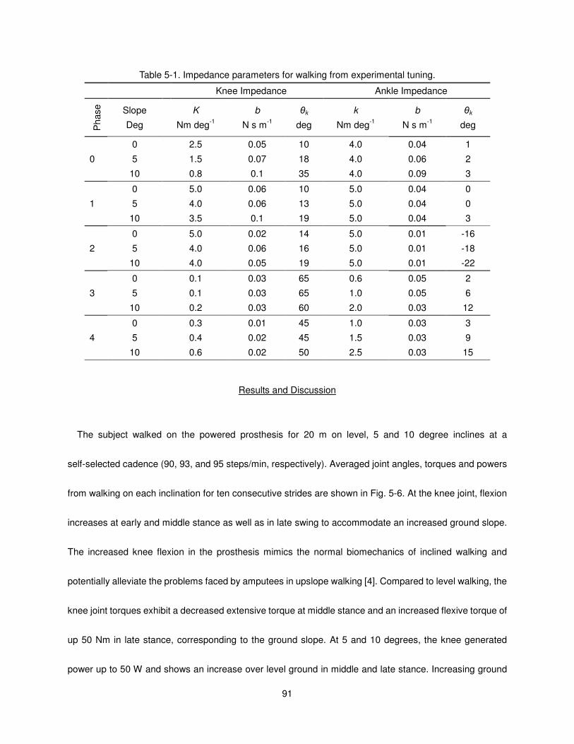
91
Table 5-1. Impedance parameters for walking from experimental tuning.
Knee Impedance Ankle Impedance P
hase
Slope
Deg
K
Nm deg-1
b
N s m-1
θk
deg
k
Nm deg-1
b
N s m-1
θk
deg
0
0 2.5 0.05 10 4.0 0.04 1
5 1.5 0.07 18 4.0 0.06 2
10 0.8 0.1 35 4.0 0.09 3
1
0 5.0 0.06 10 5.0 0.04 0
5 4.0 0.06 13 5.0 0.04 0
10 3.5 0.1 19 5.0 0.04 3
2
0 5.0 0.02 14 5.0 0.01 -16
5 4.0 0.06 16 5.0 0.01 -18
10 4.0 0.05 19 5.0 0.01 -22
3
0 0.1 0.03 65 0.6 0.05 2
5 0.1 0.03 65 1.0 0.05 6
10 0.2 0.03 60 2.0 0.03 12
4
0 0.3 0.01 45 1.0 0.03 3
5 0.4 0.02 45 1.5 0.03 9
10 0.6 0.02 50 2.5 0.03 15
Results and Discussion
The subject walked on the powered prosthesis for 20 m on level, 5 and 10 degree inclines at a
self-selected cadence (90, 93, and 95 steps/min, respectively). Averaged joint angles, torques and powers
from walking on each inclination for ten consecutive strides are shown in Fig. 5-6. At the knee joint, flexion
increases at early and middle stance as well as in late swing to accommodate an increased ground slope.
The increased knee flexion in the prosthesis mimics the normal biomechanics of inclined walking and
potentially alleviate the problems faced by amputees in upslope walking [4]. Compared to level walking, the
knee joint torques exhibit a decreased extensive torque at middle stance and an increased flexive torque of
up 50 Nm in late stance, corresponding to the ground slope. At 5 and 10 degrees, the knee generated
power up to 50 W and shows an increase over level ground in middle and late stance. Increasing ground
92
slope also translates into increased ankle joint dorsiflexion in early and middle stance and increased
plantarflexion in late stance. During swing, the ankle joint assumes a more dorsiflexed position
corresponding to increasing ground slope. The ankle torque is more plantarflexive during middle stance
with torques over 100 Nm achieved. Power at the ankle joint approaches 200 W during late stance. For
each stride, the prosthesis delivers 13.7, 16.1 and 18.5 J of net energy on average at the ankle for level, 5
and 10 degrees, respectively. It should be noted that even though no joint trajectories have been dictated by
the finite state impedance controller, the joint angles created as a result of the user prosthesis interaction
show consistency, but allow for stride by stride variance, Fig. 5-7. During the level and ascent trials, the
subject stated he felt a decreased level of exertion while using the powered prosthesis as compared with his
daily use prosthesis. He stated that the primary differences between his daily use and powered prosthesis
were active ankle push-off, powered knee swing phase and maintaining foot flat on sloped surfaces.

93
Figure 5-6. Averaged joint angles, torques and powers of the powered prosthesis for ten consecutive gait
cycles at self-selected speed for level, 5, and 10 degrees walking.
Figure 5-7. Measured joint angles of the powered prosthesis for five consecutive gait cycles at self-selected
speed for 10 degrees upslope walking.
Power consumption is one of the primary bottlenecks in advancing current powered prosthesis
technology. In order to test the feasibility of this work beyond a laboratory setting, the electrical power
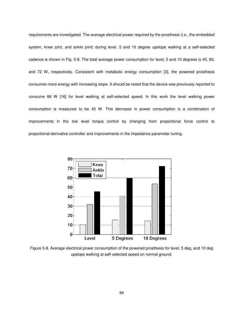
94
requirements are investigated. The average electrical power required by the prosthesis (i.e., the embedded
system, knee joint, and ankle joint) during level, 5 and 10 degree upslope walking at a self-selected
cadence is shown in Fig. 5-8. The total average power consumption for level, 5 and 10 degrees is 45, 60,
and 72 W, respectively. Consistent with metabolic energy consumption [3], the powered prosthesis
consumes more energy with increasing slope. It should be noted that the device was previously reported to
consume 66 W [16] for level walking at self-selected speed. In this work the level walking power
consumption is measured to be 45 W. This decrease in power consumption is a combination of
improvements in the low level torque control by changing from proportional force control to
proportional-derivative controller and improvements in the impedance parameter tuning.
Figure 5-8. Average electrical power consumption of the powered prosthesis for level, 5 deg, and 10 deg
upslope walking at self-selected speed on normal ground.
95
Conclusion
This work presented the extension of the control framework to slope ascent for the powered knee and
ankle prosthesis developed in prior works by the authors. The results indicate that the device has the
potential to restore near normal gait patterns in unilateral transfemoral amputees. Future work includes
comprehensive biomechanical evaluation of the powered prosthesis and the slope ascent controller on
multiple amputee subjects.
References
[1] A. N. Lay, C. J. Hass, and R. J. Gregor, “The effects of sloped surfaces on locomotion: a kinematic
and kinetic analysis,” J. of Biomechanics, vol. 39, no. 9, pp. 1621-8, 2006.
[2] A. S. McIntosh, K. T. Beatty, L. N. Dwan, and D. R. Vickers, “Gait dynamics on an inclined
walkway,” J. of Biomechanics, vol. 39, no. 13, pp. 2491-502, 2006.
[3] A. C. Bobbert, “Energy expenditure in level and grade walking,” J. of Applied Physiology vol. 15,
pp. 1015-1021, 1960.
[4] A. H. Vrieling, H. G. van Keeken, T. Schoppen, E. Otten, J. P. K. Halbertsma, A. L. Hof, and K.
Postema, “Uphill and downhill walking in unilateral lower limb amputees,” Gait & Posture, vol. 28,
no. 2, pp. 235-242, Aug, 2008.
[5] D. Winter, The Biomechanics and Motor Control of Human Gait: Normal, Elderly and Pathological,
2nd ed.: University of Waterloo Press, 1991.
[6] D. A. Winter, and S. E. Sienko, “Biomechanics of below-knee amputee gait,” J. of Biomechanics,
vol. 21, no. 5, pp. 361-367, 1988.
[7] H. Burger, J. Kuzelicki, and C. Marincek, “Transition from sitting to standing after trans-femoral
amputation,” Prosthetics and Orthotics International, vol. 29, no. 2, pp. 139-151, Aug, 2005.
[8] T. Schmalz, S. Blumentritt, and B. Marx, “Biomechanical analysis of stair ambulation in lower limb
amputees,” Gait & Posture, vol. 25, no. 2, pp. 267-278, Feb, 2007.
[9] M. Traballesi, P. Porcacchia, T. Averna, and S. Brunelli, “Energy cost of walking measurements in

96
subjects with lower limb amputations: A comparison study between floor and treadmill test,” Gait &
Posture, vol. 27, no. 1, pp. 70-75, Jan, 2008.
[10] R. L. Waters, J. Perry, D. Antonelli, and H. Hislop, “Energy cost of walking of amputees - Influence
of level of amputation,” J. of Bone and Joint Surgery-American Vol., vol. 58, no. 1, pp. 42-46, 1976.
[11] W. C. Flowers, and R. W. Mann, “Electrohydraulic knee-torque controller for a prosthesis
simulator,” ASME J. of Biomechanical Engineering, vol. 99, no. 4, pp. 3-8, 1977.
[12] S. Bedard, and P. Roy, Actuated Leg Prosthesis for Above-Knee Amputees, U. S. Patent, 2003.
[13] W. Koniuk, Self-adusting prosthetic ankle apparatus, 6,443,993, U. S. Patent, March, 23, 2001.
[14] R. Bellman, A. Holgate, and T. Sugar, “SPARKy 3: Design of an active robotic ankle prosthesis
with two actuated degrees of freedom using regenerative kinetics,” Proc. IEEE/RAS-EMBS Int.
Conf. on Biomedical Robotics and Biomechatronics, pp. 511-516, 2008.
[15] S. Au, and H. Herr, “Powered ankle-foot prosthesis,” IEEE Robotics & Automation Magazine, vol.
15, pp. 52-59, 2008.
[16] F. Sup, H. A. Varol, J. Mitchell, T. J. Withrow, and M. Goldfarb, “Self-Contained Powered Knee and
Ankle Prosthesis: Initial Evaluation on a Transfemoral Amputee,” IEEE 11th Int. Conf. on
Rehabilitation Robotics, pp. 638-644, 2009.
[17] H. A. Varol, F. Sup, and M. Goldfarb, “Real-time gait mode intent recognition of a powered knee
and ankle prosthesis for standing and walking,” Proc. IEEE/RAS-EMBS Int. Conf. on Biomedical
Robotics and Biomechatronics, pp. 66-72, 2008.
[18] H. A. Varol, F. Sup, and M. Goldfarb, “Powered Sit-to-Stand and Assistive Stand-to-Sit Framework
for a Powered Transfemoral Prosthesis,” IEEE 11th Int. Conf. on Rehabilitation Robotics, pp.
645-651, 2009.
[19] 42 U.S.C. § 12101 et seq., Americans with Disabilities Act of 1990, 1994.

97
CHAPTER VI
Contributions and Future Work
Contributions
This work aims to develop the technologies required to bring powered knee and ankle prostheses to the
commercial market, which in turn, can then bring the benefits of powered prostheses to the amputee
population. Specifically, this work accomplishes the following goals.
• Defines the electrical and mechanical power specifications for an active knee and ankle prosthesis.
• Presents a mechanical design for a self-contained, light-weight, electrically powered knee and ankle
prosthesis with onboard power, sensing elements and DC motor actuated joints.
• Develops embedded system architecture that enables both tethered and untethered operation of the
lower limb prosthesis with onboard computation, signal processing, power management, data logging,
and wireless communication.
• Presents the design of compact strain-based sensors to measure the sagittal plane moment above the
knee joint and the ground reaction forces at the heel and ball of the foot.
• Describes a general three level control architecture for powered lower limb prostheses. The high level
supervisory controller, which is the intent recognizer, infers the user’s intent based on the interaction
between the user and the prosthesis, and correspondingly switches the middle level controllers. The
middle level controllers generate torque references for the joints using a finite state machine that

98
modulates the impedance of the joints depending on the phase of the activity. The low-level controllers
are the closed-loop joint torque controllers.
• Describes the expansion and refinement of the finite-state impedance control structure to
accommodate gait at three cadences, standing, slope ascent, sitting and the associated sit-to-stand
transitions.
• Presents the validation of the prosthesis on a treadmill using an able-bodied adapter.
• Presents the validation of the device on a treadmill and over level ground tested by a unilateral
transfemoral amputee and demonstrates the ability to restore near normal biomechanical gait.
Direction of Future Work
The area of powered lower limbs is a relatively new field of research and offers many unexplored
problems that must be addressed to bring such devices to the commercial market. Future areas of research
beyond the scope of this dissertation can focus on the three main areas of powered prosthesis design:
physical design of the prosthesis, development of prosthesis controllers, and biomechanical evaluations to
assess benefits of such a device.
Prosthesis Design
The physical hardware consists of the mechanical and electrical components that comprise the powered
prosthesis. A significant requirement of the current design is that in order to generate the requisite torques
at the joints requires a transmission ratio on the order of 160:1. At high joint velocities, the ball screws turn
at over 10,000 rpm and create an unacceptable audible noise (70 dB at 1 m). The development of a
compact and efficient drive mechanism would overcome a significant hurdle and bring a commercially

99
viable powered prosthesis to the commercial market. A secondary source of audible noise is a high-pitched
frequency emitted from the commercial servo amplifiers caused by an inductance mismatch between the
servo amplifier and the motor. To alleviate this issue, a useful area of research is to develop a compact
servo amplifier better matched to the state-of-the-art brushless DC motors tuned for quiet operation. A
custom device could bring further improvements in terms of weight and geometric envelope by allowing the
amplifier to be incorporated into the structure for heat sinking. To increase the amputee population aided by
such a powered prosthesis, modularity of the design should be sought. Development of separate powered
knee and ankle devices that could work both together and independently could better serve the needs of the
transfemoral and transtibal amputee communities.
Controller Design
To cover the basic set of functionality provided by a powered lower limb, the finite-state impedance
control structures for stair ascent and decent, slope descent, cadence estimation, slope estimation, and
uneven terrain compensation need to be developed along with the corresponding supervisory control
structure. One drawback of the current finite-state control approach is the considerable amount of manual
parameter tuning. To address this issue, an automated, adaptive scheme should to be developed to bring
such a powered prosthesis to commercial market. To further increase the efficiency of the tuning process, a
more quantitative means to address the performance of the sound-side limb and whole body mechanics to
provide a more optimal set of impedance parameters. One potential embodiment of tuning would use a set
of accelerometers worn on the body during tuning on the sound side shank and thigh and on the body trunk
during tuning. Another interesting focus for future research to the development of alternative control
100
approach methodologies. One such approach is active-passive control. This method maps the entire
state-space of gait to continuous functions rather than a discrete set as in finite-state impedance control.
The approach maps passive impedance functions of the knee and ankle joints and supplements the torque
output with an active component based on sensor input that measures the user’s interaction with the leg,
such as the socket sagittal moment sensor. A further area is development of fault detection algorithms to
ensure the proper functioning of the device and prevent user injury.
Biomechanical Assessment
A near term study is planned to assess the biomechanics of the amputee subject used in Manuscripts
2 and 3 and Chapter V to study the effects of the powered knee and ankle prosthesis on amputee gait. The
measures to be studied would be gait symmetry at three walking speeds (self-selected speed and ±15% of
the self-selected speed) in terms of joint angles, moments, powers and stride length and gait posture
determined by the motion of the trunk. In addition, metabolic measures such as oxygen intake and heart
rate should be considered at the user’s self-selected speed to determine if a powered lower limb is capable
of reducing the energy expenditure of the user in level ground gait.
Long term future research areas include assessment of the benefits and effects of a powered knee and
ankle prostheses on gait and general mobility. These would include standing, transitions between sitting
and standing, ascending and descending stairs and ramps, and navigating uneven terrain. Once the
physical hardware has achieved a level development where users wear the device as their daily-use
prosthesis, a larger study should be conducted. The study, consisting of 10 or more subjects over the
course of multiple weeks, would train and accustom users to the device to assess its affect on gait quality

101
and metabolic energy consumption. In the general study of powered prosthesis, a four quadrant study
should be conducted studying the effects of combining active and passive prosthesis and the knee and
ankle. This assessment would identify benefits of power at the knee and the ankle joints and help focus
future research.


![Knee, Ankle Foot-Fall10[1]](https://img.dokumen.tips/doc/110x75/577d28cd1a28ab4e1ea542cb/knee-ankle-foot-fall101.jpg)