Embed Size (px)
Citation preview
sustainability
Article
A Novel Composite Material for FoldableBuilding Envelopes
Gianluca Rodonò 1,* , Vincenzo Sapienza 1 , Giuseppe Recca 2 andDomenico Carmelo Carbone 2
1 Department of Civil Engineering and Architecture—University of Catania (Italy) via S. Sofia 64,95125 Catania, Italy
2 Institute of Polymers, Composites and Biomaterials—National Research Council of Italy via Paolo Gaifami,18, 95126 Catania, Italy
* Correspondence: [email protected]; Tel.: +39-3891-556-134
Received: 2 July 2019; Accepted: 24 August 2019; Published: 28 August 2019�����������������
Abstract: Contemporary research is increasingly focused on studying buildings that either interactwith environmental boundaries or adapt themselves to their users’ needs. In the current literature,this kind of ability is given different names: responsivity, adaptability, smartness. These are differentways to refer to a common concept, with subtle nuances. Foldable surfaces are one of the mostinteresting geometries able to give responsivity to building components, but often their productionis complex and expensive. The aim of this research was the creation of a novel material that canprovide lightweight solutions for foldable building envelopes. This composite material can be foldedand unfolded easily, like a sheet of paper, but with a higher mechanical performance. It is madewith the thermoplastic elastomer SEBS (styrene–ethylene–butylene–styrene) as its matrix, as well as afabric reinforcement. In this paper, following an introduction to this subject, the authors present thecomposite material’s production methods and its mechanical characterization.
Keywords: textile architecture; fabric structures; origami; composite material; responsive surface
1. Introduction
At present, it is difficult to give a fixed structure to the functions carried out inside buildings viahierarchical organization and a rhythmic arrangement of spaces, because of their transitory nature.Functions tend to be ever-changing due to the contemporary lifestyle, with a consequent variability oflighting and thermal needs. The necessity of the ability to change shape is a direct consequence of thisconsideration. The kinematics may involve either the entire building including its structure—especiallyin temporary pavilions or small buildings [1]—or only certain building components [2]. In the lattercase, kinematics generally involves the envelope, which is the main interface between the buildingand its surrounding environment. Via the kinematic mechanism of the envelope, one can adjust thesolar radiation and illumination [3–6], ventilation, or acoustic behavior [7,8]. Over time, the need forkinematic mechanisms for the control of different configurations has resulted in the introduction of asystem of actuators in building components (one very common application is roller shutter controllers).The electrification of actuators and the consequent introduction of a system of sensors and a controlunit have led to a complete automation of the kinematic mechanisms as a result of certain inputs whichgive rise to the so-called adaptive or responsive buildings [9,10].
In the context of a broader definition of convertible architectural components, Frei Otto investigatesthe types of motion used to confer such properties [11]. The most used in recent architectural projectsis folding [12]. Its advantages, thanks to the properties generated by a fold on a surface, are dual.In fact, on the one hand, folds work as hinges which generate a possible rotation around the axis of the
Sustainability 2019, 11, 4684; doi:10.3390/su11174684 www.mdpi.com/journal/sustainability
Sustainability 2019, 11, 4684 2 of 17
fold [13]. On the other hand, they cause an increase in mechanical properties thanks to the so-called“form-resistance” acquired by the surface [14]. To create and control the different folding patterns thatcan be given to a surface, an appropriate reference is the oriental art of origami, which is based on twodifferent types of folds: first fold and reverse fold [15]. Today the attempt to exploit the properties oforigami surfaces is encountering growing success in the various branches of engineering, especially incombination with Smart Materials [16]. This research clearly shows that the use of folding surfacesoffers a high potential for future research, due to their mechanical and kinetic properties.
In this field, the most recent research focuses on passive systems based on an intrinsic control,characterized as such in [5], in opposition to active systems based on extrinsic control via the useof sensors and actuators which need external energy resources. Passive systems are distinguishedby their ability to self-adapt in response to certain inputs when using Smart Materials [17]. Thesecomponents perform highly in terms of management; they do not require mechanical actuators, norsensor and control systems. Conversely, however, they do not guarantee an individual control byusers for their specific requirements, and this characteristic is usually not appreciated [3]. The widevariety of interpretations of this theme is reflected in the diversification of definitions (e.g., adaptive,responsive, convertible, etc.) that are closely linked with individual studies on the subject and aretypically varied depending on the degree of automation integrated into the component [18].
This article shows the results of experimental tests for the production of an innovative andlightweight material that is suitable for use as an architectural component with an integrated kinematicmechanism. The aim was to obtain an easily controllable material, like a sheet of paper which, whenfolded, can rotate easily around the axis defined by the fold.
2. Materials
2.1. State of the Art
Contemporary approaches to the issue of the responsiveness of architectural components tendto simplify the moving parts as much as possible, avoiding the use of complex mechanisms. This isessentially due to a need for simplification of their management. Mechanical systems, even high-qualityones, require maintenance plans and operations. These are often not carried out, due to negligence orhigh costs, thus causing the premature decay of component performances. Elastic kinematics [3,19] isan alternative solution. This system is based on the use of materials which are capable of undergoing adeformation, storing energy, and returning to the initial position when no longer stressed. Thanks tothe absence of hinges, this entails a much lower need for maintenance cycles than mechanical systems,and is therefore more economically sustainable.
In recent innovative architectural designs, the elastic kinematics of components is obtainedusing composite materials such as glass-fiber-reinforced polymers (GFRPs). These were used for theconstruction of the Thematic Pavilion sunblind at the EXPO 2012 in Yeosu and for the Flectofoldprototype made at the Institute of Building Structures and Structural Design (ITKE) of the Universityof Stuttgart (Figure 1a). The latter was inspired by the deformation mechanism of the Strelitzia reginaeflower. This flower has anthers made of two closed petals to protect the pollen. When a bird restson these elements, the flexional deformation of the anther determines a rotation of the petals and theopening of the system that releases the pollen onto the bird’s body. When the bird moves away, thesystem’s elasticity reverses the deformation and closes the two petals. This movement inspired acomponent made of a fiber-reinforced polymer (FRP). This material has an advantage over traditionalmaterials used in the construction industry, such as steel or aluminum, thanks to its high elasticdeformation due to its reduced rigidity–resistance ratio. In particular, the material used is made ofa fiberglass fabric with a plain weave and weighs 80 g/m2. Tissue layers vary from four to eightdepending on the distribution of stresses on the surface. The composite matrix is made of ultra-flexibleepoxy resin. The production process is the Vacuum Assisted Process (VAP). The backbone of thecomponent is a profile produced with a pultrusion process and is bound with the lateral “wings”
Sustainability 2019, 11, 4684 3 of 17
forming an L-shaped (single-wing) or U-shaped (double-winged) system. This profile is made of GFRPoriented in the direction of longitudinal stresses. The main application of the component is in façadesolar shadings where a system of actuators generates the flexion of the central spine of the componentwhich, in turn, determines the opening of the two lateral lamellae [19,20].
The Hylite® panel is also made of composite material, consisting of a double layer of aluminumand a layer of interposed polypropylene (Figure 1b). If parallel grooves are milled into both externalaluminum surfaces, this panel can be used for folding components. The company guarantees thepossibility of performing more than 80,000 closing cycles. These properties have stimulated researchinto possible applications for deployable shelters [21].
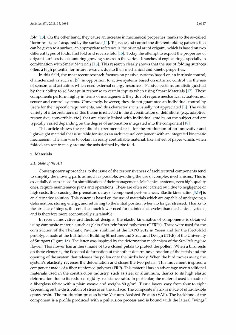
Growing attention to foldable components stimulates research not only into innovative compositematerials but also into innovative manufacturing processes of traditional materials such as wood.These innovative processes make it possible to obtain components with kinematics linked to the elasticdeformation. For instance, using a repetitive 2D cutting system managed by a computer numericalcontrol (CNC) cutter, it is possible to obtain a repetitive pattern material (RPM). These materials areendowed with an elasticity that the constituent base material does not possess (Figure 1c), but whichderives from the cutting geometry [22].
Sustainability 2019, 11, x FOR PEER REVIEW 3 of 18
façade solar shadings where a system of actuators generates the flexion of the central spine of the component which, in turn, determines the opening of the two lateral lamellae [19,20].
The Hylite® panel is also made of composite material, consisting of a double layer of aluminum and a layer of interposed polypropylene (Figure 1b). If parallel grooves are milled into both external aluminum surfaces, this panel can be used for folding components. The company guarantees the possibility of performing more than 80,000 closing cycles. These properties have stimulated research into possible applications for deployable shelters [21].
Growing attention to foldable components stimulates research not only into innovative composite materials but also into innovative manufacturing processes of traditional materials such as wood. These innovative processes make it possible to obtain components with kinematics linked to the elastic deformation. For instance, using a repetitive 2D cutting system managed by a computer numerical control (CNC) cutter, it is possible to obtain a repetitive pattern material (RPM). These materials are endowed with an elasticity that the constituent base material does not possess (Figure 1c), but which derives from the cutting geometry [22].
Figure 1. (a) Flectofold prototype photo by Julian Lienhard; (b) Hylite® panel photo by 3AComposites and Curletto and Gambarotta [21]; (c) Wooden repetitive pattern material photo by Ohshima et al. [22].
Among the numerous possible solutions, we attempted to supplant those using hinges with bending caused by the elastic deformation of a composite material, using fabrics as reinforcement and a thermoplastic elastomer (TPE) as matrix.
In recent decades, the use of composite materials in the building industry has rapidly increased, especially in the field of the so-called fabric structures [23] or textile architectures [24]. For these types of systems, the properties of the unique material used are decisive in achieving good performances, but the fabric architecture has widely diversified applications: from permanent to temporary structures, from fixed configurations to easily movable ones in relation to boundary conditions. Thus, the material’s properties are based on building requirements. It should provide protection from rain and sun and, in relation to a specific project, be more or less transparent, water-vapor-permeable, penetrable by warmth, and so on. The material has to be lightweight, but also adaptable to specific requirements. A composite material meets this objective because it is manufactured with two or more components that together endow it with properties different from the separate basic ones. A composite is made with a reinforcement (discontinuous material that is the main contributor to the strength of the composite), and a matrix that fastens the reinforcement into position, transfers the forces acting on the material to the reinforcement, and also defines the surface finishing and resistance to ageing [25]. In addition, the ways matrix and reinforcement are combined during processing have different effects on the final component.
Composite materials for textile architectures are typically fabrics, either natural or synthetic, coated with polymers. The most commonly used fabrics have widely different characteristics: from a cheap material with a short lifespan (e.g., polyethylene terephthalate, PET), to a high-performance fiber such as Aramid or polytetrafluoroethylene (PTFE). The most used natural fiber is cotton, even though it has a short lifespan of only around four or five years. Hemp and flax are more sustainable, stronger, and more UV-resistant than cotton, although today they are rarely used [26].
Figure 1. (a) Flectofold prototype photo by Julian Lienhard; (b) Hylite® panel photo by 3ACompositesand Curletto and Gambarotta [21]; (c) Wooden repetitive pattern material photo by Ohshima et al. [22].
Among the numerous possible solutions, we attempted to supplant those using hinges withbending caused by the elastic deformation of a composite material, using fabrics as reinforcement anda thermoplastic elastomer (TPE) as matrix.
In recent decades, the use of composite materials in the building industry has rapidly increased,especially in the field of the so-called fabric structures [23] or textile architectures [24]. For these typesof systems, the properties of the unique material used are decisive in achieving good performances, butthe fabric architecture has widely diversified applications: from permanent to temporary structures,from fixed configurations to easily movable ones in relation to boundary conditions. Thus, thematerial’s properties are based on building requirements. It should provide protection from rainand sun and, in relation to a specific project, be more or less transparent, water-vapor-permeable,penetrable by warmth, and so on. The material has to be lightweight, but also adaptable to specificrequirements. A composite material meets this objective because it is manufactured with two or morecomponents that together endow it with properties different from the separate basic ones. A compositeis made with a reinforcement (discontinuous material that is the main contributor to the strength of thecomposite), and a matrix that fastens the reinforcement into position, transfers the forces acting onthe material to the reinforcement, and also defines the surface finishing and resistance to ageing [25].In addition, the ways matrix and reinforcement are combined during processing have different effectson the final component.
Composite materials for textile architectures are typically fabrics, either natural or synthetic,coated with polymers. The most commonly used fabrics have widely different characteristics: from acheap material with a short lifespan (e.g., polyethylene terephthalate, PET), to a high-performancefiber such as Aramid or polytetrafluoroethylene (PTFE). The most used natural fiber is cotton, eventhough it has a short lifespan of only around four or five years. Hemp and flax are more sustainable,stronger, and more UV-resistant than cotton, although today they are rarely used [26].

Sustainability 2019, 11, 4684 4 of 17
2.2. Novel Composite Material
With these assumptions, fiber composite materials seem to be the best solution for origami surfaces.In fact, the idea is to preserve the typical characteristics of the fabric, such as light weight and aversatility similar to paper, while ensuring protection from the deterioration caused by atmosphericagents (rain, hail, sunlight, etc.). As mentioned above, this is ensured by the use of a polymer coating.
Our idea was to create a composite and then imprint a folding pattern into it post production.Once shaped, commonly used thermosetting polymers degrade if melted again. So, we used a TPEthat withstands manipulation at high temperatures to guarantee the foldability of the composite. Thetwo phases of production make it possible to customize the shape of the different components anddifferent kinematic mechanisms. Thus, the base material—an industrially produced composite—couldbe configured with a specific folding pattern for each project (Figure 2). This way, it is possible tocombine industrial production with craft, as is currently required in an increasingly pressing market.
Sustainability 2019, 11, x FOR PEER REVIEW 4 of 18
2.2. Novel Composite Material
With these assumptions, fiber composite materials seem to be the best solution for origami surfaces. In fact, the idea is to preserve the typical characteristics of the fabric, such as light weight and a versatility similar to paper, while ensuring protection from the deterioration caused by atmospheric agents (rain, hail, sunlight, etc.). As mentioned above, this is ensured by the use of a polymer coating.
Our idea was to create a composite and then imprint a folding pattern into it post production. Once shaped, commonly used thermosetting polymers degrade if melted again. So, we used a TPE that withstands manipulation at high temperatures to guarantee the foldability of the composite. The two phases of production make it possible to customize the shape of the different components and different kinematic mechanisms. Thus, the base material—an industrially produced composite—could be configured with a specific folding pattern for each project (Figure 2). This way, it is possible to combine industrial production with craft, as is currently required in an increasingly pressing market.
Figure 2. The novel composite material application: (a) as second skin to refurbish an existing building; (b) as temporary pavilion envelope.
2.3. Matrix
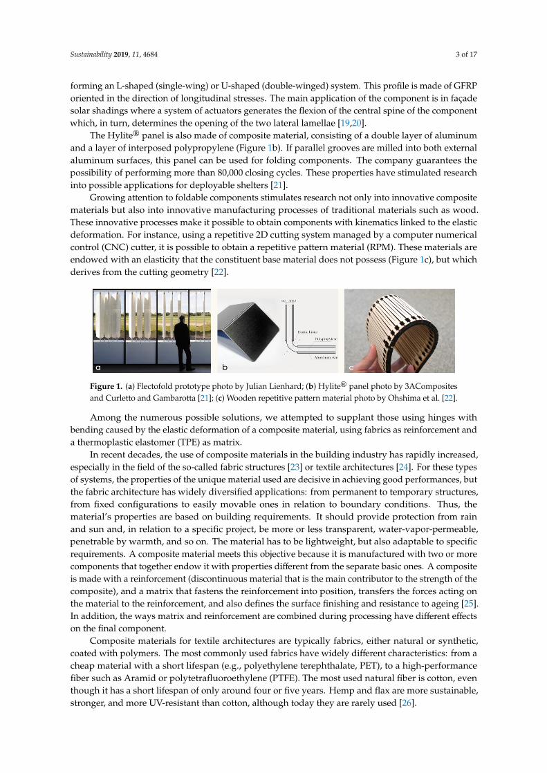
We selected SEBS (styrene–ethylene–butylene–styrene) as the thermoplastic elastomer, provided in pellets (Figure 3). Pellets were extruded with a Collin Teach Line extruder with a flat head (E16T model) and cooling roller (CR72T model) to obtain a thin film to be used as the matrix (Figure 4). For the first tests, we used a thin film with a thickness of 500 μm, but to optimize the composite by reducing the proportion of the matrix, we produced a film with a thickness of 170 μm.
Figure 3. SEBS (styrene–ethylene–butylene–styrene) pellets.
Figure 2. The novel composite material application: (a) as second skin to refurbish an existing building;(b) as temporary pavilion envelope.
2.3. Matrix
We selected SEBS (styrene–ethylene–butylene–styrene) as the thermoplastic elastomer, providedin pellets (Figure 3). Pellets were extruded with a Collin Teach Line extruder with a flat head (E16Tmodel) and cooling roller (CR72T model) to obtain a thin film to be used as the matrix (Figure 4).For the first tests, we used a thin film with a thickness of 500 µm, but to optimize the composite byreducing the proportion of the matrix, we produced a film with a thickness of 170 µm.
Sustainability 2019, 11, x FOR PEER REVIEW 4 of 18
2.2. Novel Composite Material
With these assumptions, fiber composite materials seem to be the best solution for origami surfaces. In fact, the idea is to preserve the typical characteristics of the fabric, such as light weight and a versatility similar to paper, while ensuring protection from the deterioration caused by atmospheric agents (rain, hail, sunlight, etc.). As mentioned above, this is ensured by the use of a polymer coating.
Our idea was to create a composite and then imprint a folding pattern into it post production. Once shaped, commonly used thermosetting polymers degrade if melted again. So, we used a TPE that withstands manipulation at high temperatures to guarantee the foldability of the composite. The two phases of production make it possible to customize the shape of the different components and different kinematic mechanisms. Thus, the base material—an industrially produced composite—could be configured with a specific folding pattern for each project (Figure 2). This way, it is possible to combine industrial production with craft, as is currently required in an increasingly pressing market.
Figure 2. The novel composite material application: (a) as second skin to refurbish an existing building; (b) as temporary pavilion envelope.
2.3. Matrix
We selected SEBS (styrene–ethylene–butylene–styrene) as the thermoplastic elastomer, provided in pellets (Figure 3). Pellets were extruded with a Collin Teach Line extruder with a flat head (E16T model) and cooling roller (CR72T model) to obtain a thin film to be used as the matrix (Figure 4). For the first tests, we used a thin film with a thickness of 500 μm, but to optimize the composite by reducing the proportion of the matrix, we produced a film with a thickness of 170 μm.
Figure 3. SEBS (styrene–ethylene–butylene–styrene) pellets. Figure 3. SEBS (styrene–ethylene–butylene–styrene) pellets.
Sustainability 2019, 11, 4684 5 of 17Sustainability 2019, 11, x FOR PEER REVIEW 5 of 18
Figure 4. Collin Teach Line extruder with flat head (E16T model).
2.4. Reinforcement
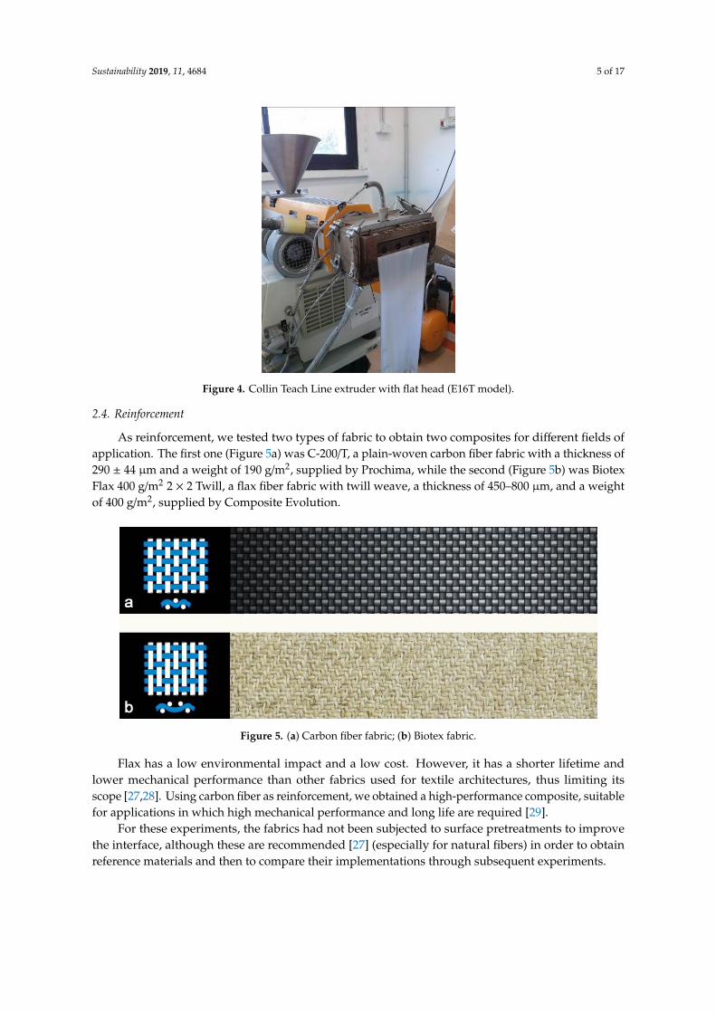
As reinforcement, we tested two types of fabric to obtain two composites for different fields of application. The first one (Figure 5a) was C-200/T, a plain-woven carbon fiber fabric with a thickness of 290 ± 44 μm and a weight of 190 g/m2, supplied by Prochima, while the second (Figure 5b) was Biotex Flax 400 g/m2 2 × 2 Twill, a flax fiber fabric with twill weave, a thickness of 450–800 μm, and a weight of 400 g/m2, supplied by Composite Evolution.
Figure 5. (a) Carbon fiber fabric; (b) Biotex fabric.
Flax has a low environmental impact and a low cost. However, it has a shorter lifetime and lower mechanical performance than other fabrics used for textile architectures, thus limiting its scope [27,28]. Using carbon fiber as reinforcement, we obtained a high-performance composite, suitable for applications in which high mechanical performance and long life are required [29].
For these experiments, the fabrics had not been subjected to surface pretreatments to improve the interface, although these are recommended [27] (especially for natural fibers) in order to obtain reference materials and then to compare their implementations through subsequent experiments.
Figure 4. Collin Teach Line extruder with flat head (E16T model).
2.4. Reinforcement
As reinforcement, we tested two types of fabric to obtain two composites for different fields ofapplication. The first one (Figure 5a) was C-200/T, a plain-woven carbon fiber fabric with a thickness of290 ± 44 µm and a weight of 190 g/m2, supplied by Prochima, while the second (Figure 5b) was BiotexFlax 400 g/m2 2 × 2 Twill, a flax fiber fabric with twill weave, a thickness of 450–800 µm, and a weightof 400 g/m2, supplied by Composite Evolution.
Sustainability 2019, 11, x FOR PEER REVIEW 5 of 18
Figure 4. Collin Teach Line extruder with flat head (E16T model).
2.4. Reinforcement
As reinforcement, we tested two types of fabric to obtain two composites for different fields of application. The first one (Figure 5a) was C-200/T, a plain-woven carbon fiber fabric with a thickness of 290 ± 44 μm and a weight of 190 g/m2, supplied by Prochima, while the second (Figure 5b) was Biotex Flax 400 g/m2 2 × 2 Twill, a flax fiber fabric with twill weave, a thickness of 450–800 μm, and a weight of 400 g/m2, supplied by Composite Evolution.
Figure 5. (a) Carbon fiber fabric; (b) Biotex fabric.
Flax has a low environmental impact and a low cost. However, it has a shorter lifetime and lower mechanical performance than other fabrics used for textile architectures, thus limiting its scope [27,28]. Using carbon fiber as reinforcement, we obtained a high-performance composite, suitable for applications in which high mechanical performance and long life are required [29].
For these experiments, the fabrics had not been subjected to surface pretreatments to improve the interface, although these are recommended [27] (especially for natural fibers) in order to obtain reference materials and then to compare their implementations through subsequent experiments.
Figure 5. (a) Carbon fiber fabric; (b) Biotex fabric.
Flax has a low environmental impact and a low cost. However, it has a shorter lifetime andlower mechanical performance than other fabrics used for textile architectures, thus limiting itsscope [27,28]. Using carbon fiber as reinforcement, we obtained a high-performance composite, suitablefor applications in which high mechanical performance and long life are required [29].
For these experiments, the fabrics had not been subjected to surface pretreatments to improvethe interface, although these are recommended [27] (especially for natural fibers) in order to obtainreference materials and then to compare their implementations through subsequent experiments.
Sustainability 2019, 11, 4684 6 of 17
3. Methods
3.1. Composite Creation and Setting of Production Parameters
To obtain the composite material we used a planar hot press to thermoform a layer of thin SEBSfilm and fabric. The press used was type PM20, produced by Campana s.r.l. The different parametersfor optimizing production through the thermoforming of the composite are:
• Matrix-reinforcement ratio;• Pressure;• Times.
These parameters were not defined a priori, but were identified through the first production testsof the material. The thermoforming temperature was set at 180 ◦C. This was sufficient to obtain a goodinterpenetration among the materials, but not so high as to cause SEBS degradation.
3.2. Preliminary Analyses and Optimization of Production Parameters
The specimens were subjected to preliminary analyses (visual, tactile, thickness, cross-section)that made it possible to optimize the production parameters. The specimens that passed these testswere subjected to cross-section analysis, to verify the interface between matrix and reinforcement.
3.2.1. Visual Analysis
The purpose of this analysis was to detect—through observation—any defects related to theproduction process which might compromise the functionality of the basic material.
The main defects found were:
• The presence of air bubbles;• The delocalization of reinforcement fibers;• Burning of the reinforcement.
3.2.2. Tactile Analysis
For a sensory control of the product, the surface of the composite was rubbed with the palm of thehand, to detect any perceptible presence of unevenness in thickness and consistency, which are clearindications of faulty production.
3.2.3. Thickness
The samples made were subjected to measurements with a micrometer, and at least fivemeasurements were taken to verify the constancy of thickness as evidence of a proper composition andfusion of the matrix with the reinforcement.
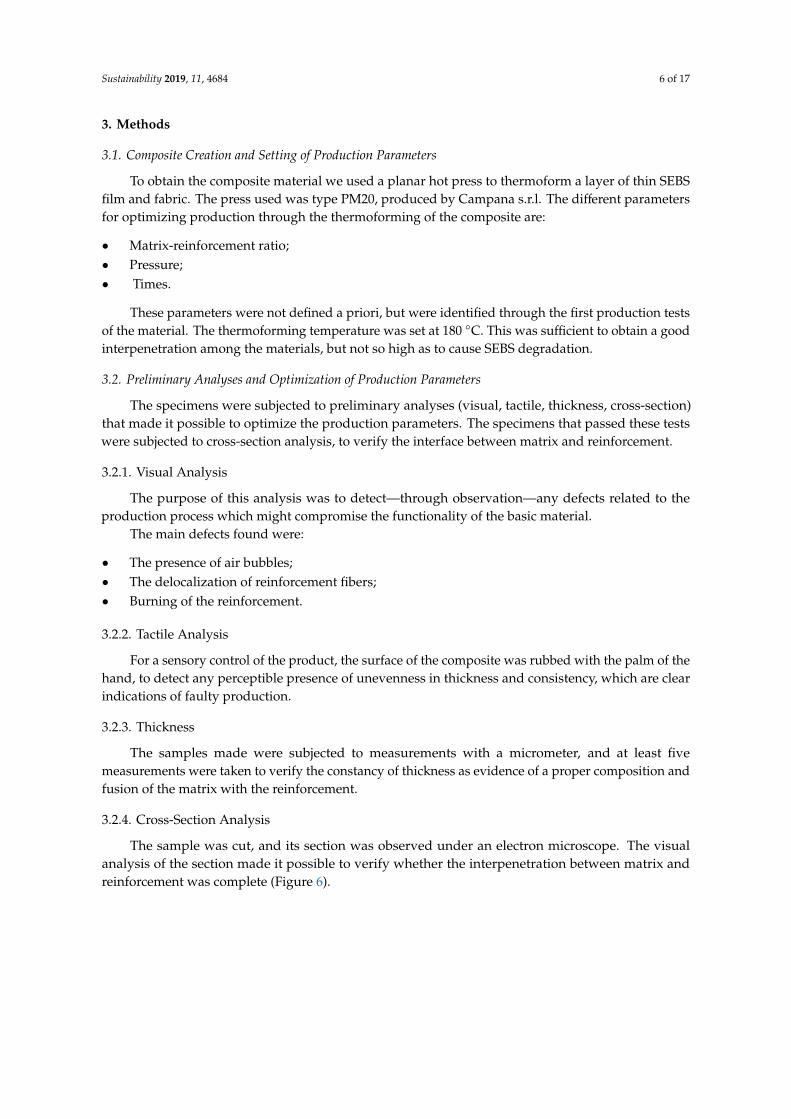
3.2.4. Cross-Section Analysis
The sample was cut, and its section was observed under an electron microscope. The visualanalysis of the section made it possible to verify whether the interpenetration between matrix andreinforcement was complete (Figure 6).
Sustainability 2019, 11, 4684 7 of 17Sustainability 2019, 11, x FOR PEER REVIEW 7 of 18
Figure 6. Cross section of SEBS–Biotex Composite.
3.3. Creation of the Folding Pattern
It is necessary to carry out a secondary thermoforming process to create a specific folding pattern on the composite material and, to do that, a mold must be made. The high costs for the construction of a professional metal mold led to the choice of an alternative route through rapid prototyping with the use of 3D printers. However, those available for experimentation work with polymeric materials which are not appropriate for molds for heated presses, since they are not good thermal conductors. Therefore, using the rapid prototyping method, we created a sort of disposable formwork to fill with a two-component epoxy resin and copper powder, in a weight ratio of 10:1. The mixture of the two elements was then used as a mold for the material.
3.4. Mechanical Characterization
The mechanical characterization of the tested composite materials consists of the determination of Young’s modulus (E) and the shear modulus (G), as the basic data necessary to be able to undertake the study of the mechanical behavior of continuous surfaces made with such materials. To do this, two tests were chosen: a uniaxial tensile test on specimens with a reinforcement warp arranged parallel to the traction axis, and a bias extension test with a reinforcement warp arranged at 45° with respect to the traction axis.
3.4.1. Uniaxial Tensile Test
This test was an extensional test on a strip of the composite with a reinforcement warp oriented parallel to the axis of the specimen. It was carried out following the directives of the UNI EN ISO 527-4 standards. It prescribes the use of rectangular specimens of type 2 (without end tabs) or 3 (with end tabs) for composites reinforced with multidirectional continuous fibers, referring to the requirements of UNI EN ISO 527-1, point 5.1, for the choice. The specimens in SEBS–Biotex were made according to the indications of type 2, with L3 = 200 mm, L = 150 mm, and b1 = 25 mm (Figure 7a). Type 2 was satisfactory for the success of the test. Conversely, with the SEBS–Carbon specimens, even though they were made with the same geometry, tests were unsuccessful due to slipping. In such cases, UNI EN ISO 527-1, point 5.1, prescribes the use of type 3, rectangular but with ends tabs (Figure 7b). Therefore, it was decided to make PMMA (polymethylmethacrylate) beads glued to the composite. Different glues were tested, with the final choice falling on ethyl cyanoacrylate, which guaranteed the adhesion of the heel from the composite during tests.
The tests were performed with a Zwick-Roell z050 tabletop testing machine (Figure 8) with a 1 kN load cell for the SEBS–Biotex and 50 kN for the SEBS–Carbon, while the test speed was set at 2 mm/min. At least five tests were performed for each sample type.
Figure 6. Cross section of SEBS–Biotex Composite.
3.3. Creation of the Folding Pattern
It is necessary to carry out a secondary thermoforming process to create a specific folding patternon the composite material and, to do that, a mold must be made. The high costs for the construction ofa professional metal mold led to the choice of an alternative route through rapid prototyping withthe use of 3D printers. However, those available for experimentation work with polymeric materialswhich are not appropriate for molds for heated presses, since they are not good thermal conductors.Therefore, using the rapid prototyping method, we created a sort of disposable formwork to fill witha two-component epoxy resin and copper powder, in a weight ratio of 10:1. The mixture of the twoelements was then used as a mold for the material.
3.4. Mechanical Characterization
The mechanical characterization of the tested composite materials consists of the determination ofYoung’s modulus (E) and the shear modulus (G), as the basic data necessary to be able to undertakethe study of the mechanical behavior of continuous surfaces made with such materials. To do this, twotests were chosen: a uniaxial tensile test on specimens with a reinforcement warp arranged parallel tothe traction axis, and a bias extension test with a reinforcement warp arranged at 45◦ with respect tothe traction axis.
3.4.1. Uniaxial Tensile Test
This test was an extensional test on a strip of the composite with a reinforcement warp orientedparallel to the axis of the specimen. It was carried out following the directives of the UNI EN ISO 527-4standards. It prescribes the use of rectangular specimens of type 2 (without end tabs) or 3 (with endtabs) for composites reinforced with multidirectional continuous fibers, referring to the requirementsof UNI EN ISO 527-1, point 5.1, for the choice. The specimens in SEBS–Biotex were made according tothe indications of type 2, with L3 = 200 mm, L = 150 mm, and b1 = 25 mm (Figure 7a). Type 2 wassatisfactory for the success of the test. Conversely, with the SEBS–Carbon specimens, even though theywere made with the same geometry, tests were unsuccessful due to slipping. In such cases, UNI ENISO 527-1, point 5.1, prescribes the use of type 3, rectangular but with ends tabs (Figure 7b). Therefore,it was decided to make PMMA (polymethylmethacrylate) beads glued to the composite. Differentglues were tested, with the final choice falling on ethyl cyanoacrylate, which guaranteed the adhesionof the heel from the composite during tests.
The tests were performed with a Zwick-Roell z050 tabletop testing machine (Figure 8) with a 1 kNload cell for the SEBS–Biotex and 50 kN for the SEBS–Carbon, while the test speed was set at 2 mm/min.At least five tests were performed for each sample type.

Sustainability 2019, 11, 4684 8 of 17Sustainability 2019, 11, x FOR PEER REVIEW 8 of 18
Figure 7. Uniaxial tensile test specimen dimensions. PMMA: polymethylmethacrylate.
Figure 8. Zwick-Roell z050 tabletop testing machine.
3.4.2. Bias Extension Test
This was an extensional test on a strip of the composite with reinforcement warp fiber oriented at 45° with respect to the axis of the specimen. The tests were performed on rectangular samples of 150 × 50 mm2 with a distance L0 equal to 100 mm following the previously described regulation.
a
b
Figure 7. Uniaxial tensile test specimen dimensions. PMMA: polymethylmethacrylate. (a) SEBS-BIOTEXComposite (b) SEBS-Carbon Fiber Fabric Composite.
Sustainability 2019, 11, x FOR PEER REVIEW 8 of 18
Figure 7. Uniaxial tensile test specimen dimensions. PMMA: polymethylmethacrylate.
Figure 8. Zwick-Roell z050 tabletop testing machine.
3.4.2. Bias Extension Test
This was an extensional test on a strip of the composite with reinforcement warp fiber oriented at 45° with respect to the axis of the specimen. The tests were performed on rectangular samples of 150 × 50 mm2 with a distance L0 equal to 100 mm following the previously described regulation.
a
b
Figure 8. Zwick-Roell z050 tabletop testing machine.
3.4.2. Bias Extension Test
This was an extensional test on a strip of the composite with reinforcement warp fiber orientedat 45◦ with respect to the axis of the specimen. The tests were performed on rectangular samples of150 × 50 mm2 with a distance L0 equal to 100 mm following the previously described regulation.
Sustainability 2019, 11, 4684 9 of 17
These samples were tested using a 2 kN load cell. The imposed speed was 3 mm/min and thepressure of jaws on the specimen was 30 N/m.
4. Results
4.1. Production Parameters
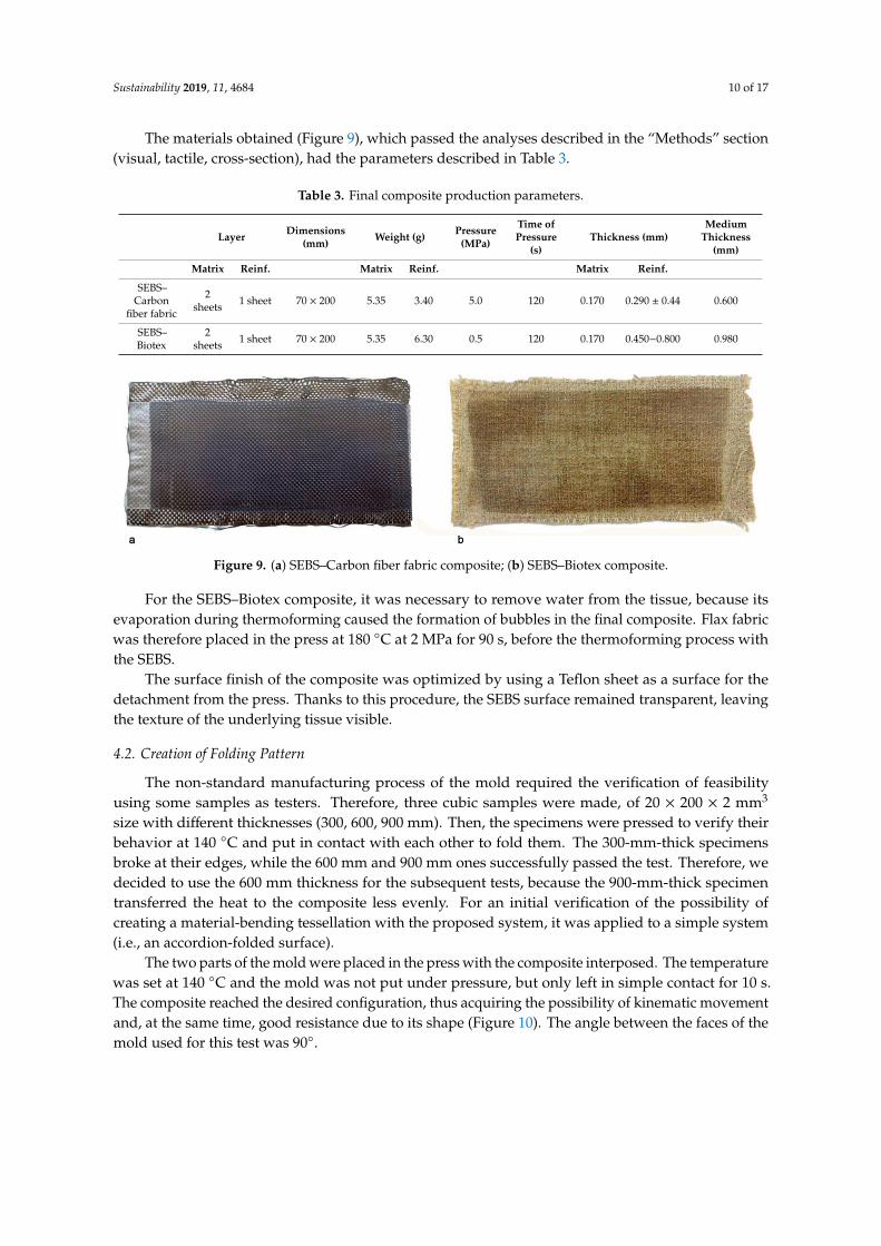
The optimization of the material production process (Tables 1 and 2) produced a composite inwhich the optimum matrix–reinforcement ratio was obtained using two layers of matrix with oneinterposed reinforcement layer. The optimization of the composite was accomplished by reducing thepresence of the SEBS to a minimum, thus obtaining a composite as light and thin as possible.
Table 1. SEBS–Carbon fiber fabric composite.
Specimen Layer Weight (g) Pressure(MPa)
Time ofPressure
(s)Thickness (mm)
MediumThickness
(mm)Matrix Reinforcement Matrix Reinforcement
S4C1_14 sheets of
SEBS 0.5 mm1 sheet of carbon
fiber fabric
x x 1 x 2.15 2.18 1.95 2.20 2.02 2.10S4C1_2 x x 2 x 1.95 1.83 2.07 2.10 1.93 1.98S4C1_3 x x 3 x 1.92 1.80 1.84 1.89 1.75 1.84S4C1_4 x x 4 x 1.82 1.72 1.70 1.72 1.60 1.71
note _For a better control of the composite it is appropriate to record the weights of the materials before thermoforming them._Minimize the thickness to optimize the performance of the material: more reinforcement and less matrix.
S4C2_44 sheets of
SEBS 0.5 mm2 sheet of carbon
fiber fabric
23.22 7.95 4 x 1.13 1.12 1.13 1.20 1.15 1.15S4C2_6 22.82 7.22 6 x 0.94 0.97 1.03 1.08 1.00 1.00S4C2_18 23.46 7.68 18 x 0.66 0.65 0.70 0.76 0.71 0.70
note _The pressure time affects the result: it should be recorded.S4C2_20_90 4 sheets of
SEBS 0.5 mm2 sheet of carbon
fiber fabric23.36 6.95 20 90 0.65 0.66 0.61 0.66 0.64 0.64
S4C2_25_90 16.75 7.88 25 90 0.63 0.56 0.50 0.63 0.60 0.58S3C2_5_60
3 sheets ofSEBS 0.5 mm
2 sheet of carbonfiber fabric
16.54 5.78 5 60 0.62 0.60 0.64 0.63 0.68 0.58S3C2_15_60 15 60S3C2_5_150 16.35 6.24 5 150S3C2_10_60 10 60S3C2_1_180
39.7 5.971 180
S3C2_5_180 5 180S3C2_10_60 10 60
note_Testing with SEBS with lower surface development than fibers to try to reduce the amount of polymer._SEBS “pulls the fibers” and dislocates it. does not reduce the thickness. Weak samples._It is advisable to program other tests with SEBS and reinforcement of the same size.
S3C2_2_903 sheets of
SEBS0.17 mm
2 sheet of carbonfiber fabric 5.8 4.74 2 90
note _A preliminary analysis to the touch showed surface roughness. We replace baking paper with Teflon sheets for the detachment from the press._Then visual analysis and analysis to the touch show more regular and uniform surfaces.
S2C1_0.2_120
2 sheets ofSEBS 0.17
mm
1 sheet of carbonfiber fabric
5.28 3.2 0.2 60S2C1_0.5_120 5.25 3.44 0.5 120S2C1_1_120 5.4 3.3 1 60S2C1_1_120 5.2 3.45 1 120S2C1_4_120 5.4 3.45 4 120S2C1_5_120 5.6 3.38 5 120 0.58 0.58 0.63 0.61 0.61 0.60
note _At a pressure of 5 MPa, a more uniform distribution of SEBS is obtained.
Table 2. SEBS–Biotex composite.
Specimen Layer Weight (g) Pressure(MPa)
Time ofPressure
(s)Thickness (mm)
MediumThickness
(mm)Matrix Reinforcement Matrix Reinforcement
S4B1_14 sheets of
SEBS 0.5 mm1 sheet of Biotex
x x 1 x 2.25 2.18 2.22 2.30 2.17 2.22S4B1_2 x x 2 x 2.05 2.12 1.74 1.89 1.92 1.94S4B1_3 x x 3 x 2.18 2.14 2.00 2.15 2.07 2.11S4B1_4 x x 4 x 1.73 1.89 1.87 2.18 2.24 1.98
note _For a better control of the composite it is appropriate to record the weights of the materials before thermoforming them._Minimize the thickness to optimize the performance of the material: more reinforcement and less matrix.
S2B1_2_602 sheet of
SEBS0.17 mm
1 sheet of Biotex 4.54 5.4 2 60 0.78 0.74 0.73 0.70 0.78 0.75
note_A preliminary analysis to the touch showed surface roughness. To ensure a better separation from the press machine. we replace baking paperwith Teflon sheets._Then visual analysis and analysis to the touch show more regular and uniform surfaces.
S2B1_2_60 2 sheet ofSEBS
0.17 mm1 sheet of Biotex
4.62 5.8 2 60 0.77 0.77 0.75 0.78 0.77 0.77S2B1_1_90 4.69 5.3 1 90 0.77 0.76 0.75 0.71 0.77 0.75
S2B1_0.5_120 4.71 5.58 0.5 120 0.98 1.08 0.99 1.02
note _The visual analysis shows a non-uniform distribution of the SEBS with many air bubbles that may be related to the presence of water in the fabric._As a possible solution we have ironed the fabric in the press at 180 ◦C for 90 s at 2 MPa. pressed slowly to not move the fibers.
S2B1D_0.5_1202 sheet of
SEBS0.17 mm
1 sheet of Biotex 5.54 6.25 0.5 120 0.92 1.04 0.98 0.98
note _The visual analysis of the sample shows the absence of air bubbles._The sample exceeds the visual and tactile analysis and it is subjected to Cross section analysis: good matrix-reinforcement interface.
Sustainability 2019, 11, 4684 10 of 17
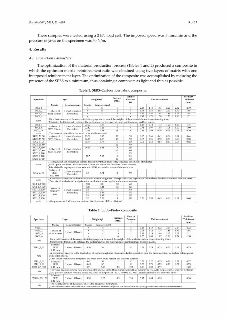
The materials obtained (Figure 9), which passed the analyses described in the “Methods” section(visual, tactile, cross-section), had the parameters described in Table 3.
Table 3. Final composite production parameters.
Layer Dimensions(mm) Weight (g) Pressure
(MPa)
Time ofPressure
(s)Thickness (mm)
MediumThickness
(mm)
Matrix Reinf. Matrix Reinf. Matrix Reinf.
SEBS–Carbon
fiber fabric
2sheets 1 sheet 70 × 200 5.35 3.40 5.0 120 0.170 0.290 ± 0.44 0.600
SEBS–Biotex
2sheets 1 sheet 70 × 200 5.35 6.30 0.5 120 0.170 0.450−0.800 0.980
Sustainability 2019, 11, x FOR PEER REVIEW 10 of 18
Table 2. SEBS–Biotex composite.
Specimen Layer Weight (g) Pressure (MPa)
Time of pressure (s)
Thickness (mm) Medium thickness
(mm) Matrix Reinforcement Matrix Reinforcement
S4B1_1
4 sheets of SEBS 0.5
mm
1 sheet of Biotex
x x 1 x 2.25 2.18 2.22 2.30 2.17 2.22
S4B1_2 x x 2 x 2.05 2.12 1.74 1.89 1.92 1.94
S4B1_3 x x 3 x 2.18 2.14 2.00 2.15 2.07 2.11
S4B1_4 x x 4 x 1.73 1.89 1.87 2.18 2.24 1.98
note _For a better control of the composite it is appropriate to record the weights of the materials before thermoforming them.
_Minimize the thickness to optimize the performance of the material: more reinforcement and less matrix.
S2B1_2_60 2 sheet of SEBS 0.17
1 sheet of Biotex
4.54 5.4 2 60 0.78 0.74 0.73 0.70 0.78 0.75
note _A preliminary analysis to the touch showed surface roughness. To ensure a better separation from the press machine. we
replace baking paper with Teflon sheets. _Then visual analysis and analysis to the touch show more regular and uniform surfaces.
S2B1_2_60 2 sheet of SEBS 0.17
mm
1 sheet of Biotex
4.62 5.8 2 60 0.77 0.77 0.75 0.78 0.77 0.77
S2B1_1_90 4.69 5.3 1 90 0.77 0.76 0.75 0.71 0.77 0.75
S2B1_0.5_120 4.71 5.58 0.5 120 0.98 1.08 0.99 1.02
note _The visual analysis shows a non-uniform distribution of the SEBS with many air bubbles that may be related to the presence
of water in the fabric. _As a possible solution we have ironed the fabric in the press at 180 °C for 90 s at 2 MPa. pressed slowly to not move the fibers.
S2B1D_0.5_120 2 sheet of SEBS 0.17
1 sheet of Biotex
5.54 6.25 0.5 120 0.92 1.04 0.98 0.98
note _The visual analysis of the sample shows the absence of air bubbles.
_The sample exceeds the visual and tactile analysis and it is subjected to Cross section analysis: good matrix-reinforcement interface.
The materials obtained (Figure 9), which passed the analyses described in the “Methods” section (visual, tactile, cross-section), had the parameters described in Table 3.
Table 3. Final composite production parameters.
Layer Dimensions
(mm) Weight (g)
Pressure (MPa)
Time of Pressure
(s) Thickness (mm)
Medium Thickness
(mm) Matrix Reinf. Matrix Reinf. Matrix Reinf.
SEBS–Carbon
fiber fabric
2 sheets
1 sheet 70 × 200 5.35 3.40 5.0 120 0.170 0.290 ±
0.44 0.600
SEBS–Biotex
2 sheets
1 sheet 70 × 200 5.35 6.30 0.5 120 0.170 0.450−0
.800 0.980
Figure 9. (a) SEBS–Carbon fiber fabric composite; (b) SEBS–Biotex composite.
For the SEBS–Biotex composite, it was necessary to remove water from the tissue, because its evaporation during thermoforming caused the formation of bubbles in the final composite. Flax fabric was therefore placed in the press at 180 °C at 2 MPa for 90 s, before the thermoforming process with the SEBS.
Figure 9. (a) SEBS–Carbon fiber fabric composite; (b) SEBS–Biotex composite.
For the SEBS–Biotex composite, it was necessary to remove water from the tissue, because itsevaporation during thermoforming caused the formation of bubbles in the final composite. Flax fabricwas therefore placed in the press at 180 ◦C at 2 MPa for 90 s, before the thermoforming process withthe SEBS.
The surface finish of the composite was optimized by using a Teflon sheet as a surface for thedetachment from the press. Thanks to this procedure, the SEBS surface remained transparent, leavingthe texture of the underlying tissue visible.
4.2. Creation of Folding Pattern
The non-standard manufacturing process of the mold required the verification of feasibilityusing some samples as testers. Therefore, three cubic samples were made, of 20 × 200 × 2 mm3
size with different thicknesses (300, 600, 900 mm). Then, the specimens were pressed to verify theirbehavior at 140 ◦C and put in contact with each other to fold them. The 300-mm-thick specimensbroke at their edges, while the 600 mm and 900 mm ones successfully passed the test. Therefore, wedecided to use the 600 mm thickness for the subsequent tests, because the 900-mm-thick specimentransferred the heat to the composite less evenly. For an initial verification of the possibility ofcreating a material-bending tessellation with the proposed system, it was applied to a simple system(i.e., an accordion-folded surface).
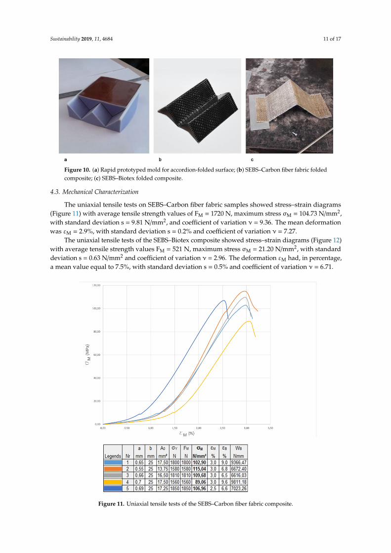
The two parts of the mold were placed in the press with the composite interposed. The temperaturewas set at 140 ◦C and the mold was not put under pressure, but only left in simple contact for 10 s.The composite reached the desired configuration, thus acquiring the possibility of kinematic movementand, at the same time, good resistance due to its shape (Figure 10). The angle between the faces of themold used for this test was 90◦.
Sustainability 2019, 11, 4684 11 of 17
Sustainability 2019, 11, x FOR PEER REVIEW 11 of 18
The surface finish of the composite was optimized by using a Teflon sheet as a surface for the detachment from the press. Thanks to this procedure, the SEBS surface remained transparent, leaving the texture of the underlying tissue visible.
4.2. Creation of Folding Pattern
The non-standard manufacturing process of the mold required the verification of feasibility using some samples as testers. Therefore, three cubic samples were made, of 20 × 200 × 2 mm3 size with different thicknesses (300, 600, 900 mm). Then, the specimens were pressed to verify their behavior at 140 °C and put in contact with each other to fold them. The 300-mm-thick specimens broke at their edges, while the 600 mm and 900 mm ones successfully passed the test. Therefore, we decided to use the 600 mm thickness for the subsequent tests, because the 900-mm-thick specimen transferred the heat to the composite less evenly. For an initial verification of the possibility of creating a material-bending tessellation with the proposed system, it was applied to a simple system (i.e., an accordion-folded surface).
The two parts of the mold were placed in the press with the composite interposed. The temperature was set at 140 °C and the mold was not put under pressure, but only left in simple contact for 10 s. The composite reached the desired configuration, thus acquiring the possibility of kinematic movement and, at the same time, good resistance due to its shape (Figure 10). The angle between the faces of the mold used for this test was 90°.
Figure 10. (a) Rapid prototyped mold for accordion-folded surface; (b) SEBS–Carbon fiber fabric folded composite; (c) SEBS–Biotex folded composite.
4.3. Mechanical Characterization
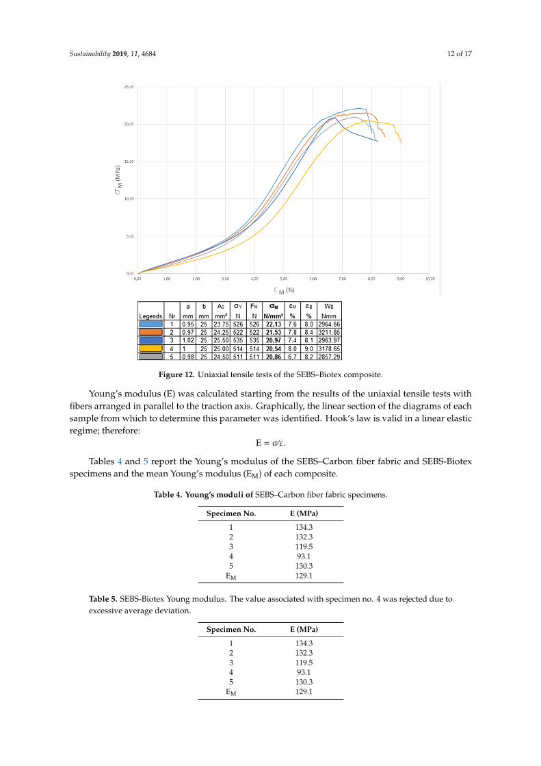
The uniaxial tensile tests on SEBS–Carbon fiber fabric samples showed stress–strain diagrams (Figure 11) with average tensile strength values of FM = 1720 N, maximum stress σM = 104.73 N/mm2, with standard deviation s = 9.81 N/mm2, and coefficient of variation ν = 9.36. The mean deformation was εM = 2.9%, with standard deviation s = 0.2% and coefficient of variation ν = 7.27.
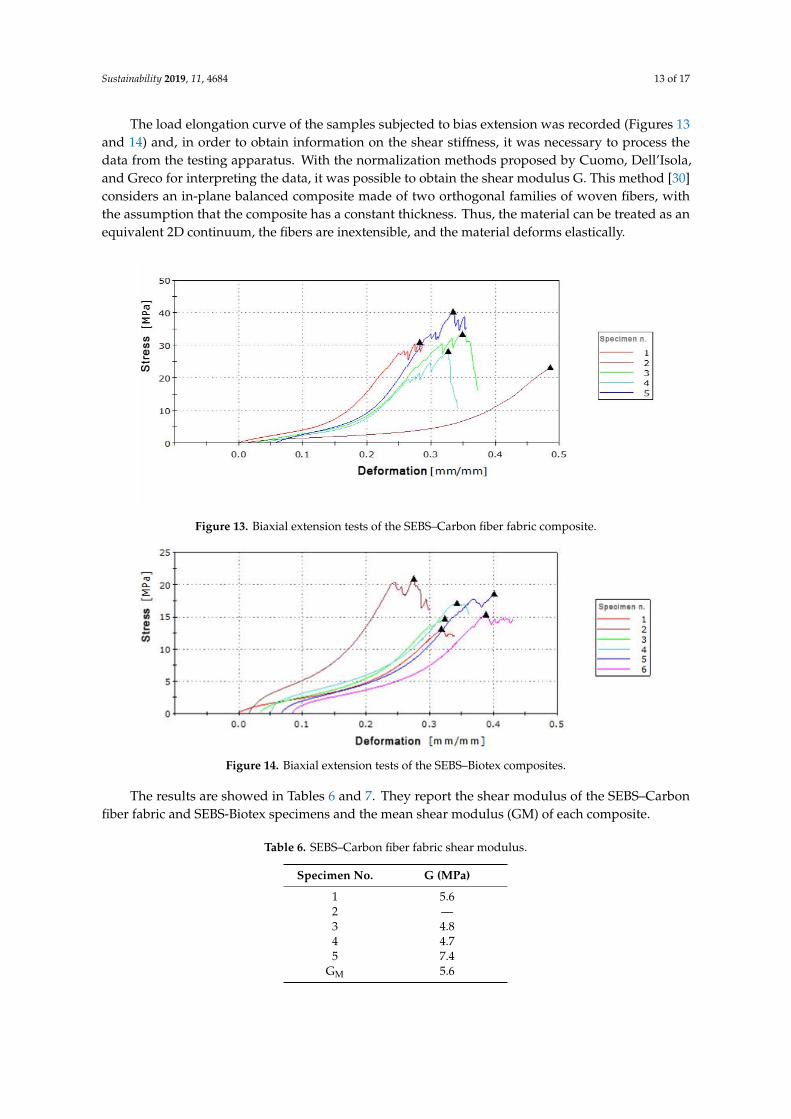
The uniaxial tensile tests of the SEBS–Biotex composite showed stress–strain diagrams (Figure 12) with average tensile strength values FM = 521 N, maximum stress σM = 21.20 N/mm2, with standard deviation s = 0.63 N/mm2 and coefficient of variation ν = 2.96. The deformation εM had, in percentage, a mean value equal to 7.5%, with standard deviation s = 0.5% and coefficient of variation ν = 6.71.
Figure 10. (a) Rapid prototyped mold for accordion-folded surface; (b) SEBS–Carbon fiber fabric foldedcomposite; (c) SEBS–Biotex folded composite.
4.3. Mechanical Characterization
The uniaxial tensile tests on SEBS–Carbon fiber fabric samples showed stress–strain diagrams(Figure 11) with average tensile strength values of FM = 1720 N, maximum stress σM = 104.73 N/mm2,with standard deviation s = 9.81 N/mm2, and coefficient of variation ν = 9.36. The mean deformationwas εM = 2.9%, with standard deviation s = 0.2% and coefficient of variation ν = 7.27.
The uniaxial tensile tests of the SEBS–Biotex composite showed stress–strain diagrams (Figure 12)with average tensile strength values FM = 521 N, maximum stress σM = 21.20 N/mm2, with standarddeviation s = 0.63 N/mm2 and coefficient of variation ν = 2.96. The deformation εM had, in percentage,a mean value equal to 7.5%, with standard deviation s = 0.5% and coefficient of variation ν = 6.71.Sustainability 2019, 11, x FOR PEER REVIEW 12 of 18
Figure 11. Uniaxial tensile tests of the SEBS–Carbon fiber fabric composite.
Figure 12. Uniaxial tensile tests of the SEBS–Biotex composite.
Figure 11. Uniaxial tensile tests of the SEBS–Carbon fiber fabric composite.
Sustainability 2019, 11, 4684 12 of 17
Sustainability 2019, 11, x FOR PEER REVIEW 12 of 18
Figure 11. Uniaxial tensile tests of the SEBS–Carbon fiber fabric composite.
Figure 12. Uniaxial tensile tests of the SEBS–Biotex composite. Figure 12. Uniaxial tensile tests of the SEBS–Biotex composite.
Young’s modulus (E) was calculated starting from the results of the uniaxial tensile tests withfibers arranged in parallel to the traction axis. Graphically, the linear section of the diagrams of eachsample from which to determine this parameter was identified. Hook’s law is valid in a linear elasticregime; therefore:
E = σ⁄ε.
Tables 4 and 5 report the Young’s modulus of the SEBS–Carbon fiber fabric and SEBS-Biotexspecimens and the mean Young’s modulus (EM) of each composite.
Table 4. Young’s moduli of SEBS–Carbon fiber fabric specimens.
Specimen No. E (MPa)
1 134.32 132.33 119.54 93.15 130.3
EM 129.1
Table 5. SEBS-Biotex Young modulus. The value associated with specimen no. 4 was rejected due toexcessive average deviation.
Specimen No. E (MPa)
1 134.32 132.33 119.54 93.15 130.3
EM 129.1
Sustainability 2019, 11, 4684 13 of 17
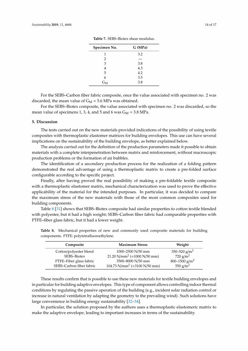
The load elongation curve of the samples subjected to bias extension was recorded (Figures 13and 14) and, in order to obtain information on the shear stiffness, it was necessary to process thedata from the testing apparatus. With the normalization methods proposed by Cuomo, Dell’Isola,and Greco for interpreting the data, it was possible to obtain the shear modulus G. This method [30]considers an in-plane balanced composite made of two orthogonal families of woven fibers, withthe assumption that the composite has a constant thickness. Thus, the material can be treated as anequivalent 2D continuum, the fibers are inextensible, and the material deforms elastically.
Sustainability 2019, 11, x FOR PEER REVIEW 13 of 18
Young’s modulus (E) was calculated starting from the results of the uniaxial tensile tests with fibers arranged in parallel to the traction axis. Graphically, the linear section of the diagrams of each sample from which to determine this parameter was identified. Hook’s law is valid in a linear elastic regime; therefore:
E = σ⁄ε.
Tables 5 and 6 report the Young’s modulus of the SEBS–Carbon fiber fabric and SEBS-Biotex specimens and the mean Young’s modulus (EM) of each composite.
Table 5. Young’s moduli of SEBS–Carbon fiber fabric specimens.
Specimen No. E (MPa) 1 134.3 2 132.3 3 119.5 4 93.1 5 130.3
EM 129.1
Table 6. SEBS-Biotex Young modulus. The value associated with specimen no. 4 was rejected due to excessive average deviation.
Specimen No. E (MPa) 1 134.3 2 132.3 3 119.5 4 93.1 5 130.3
EM 129.1
The load elongation curve of the samples subjected to bias extension was recorded (Figures 13 and 14) and, in order to obtain information on the shear stiffness, it was necessary to process the data from the testing apparatus. With the normalization methods proposed by Cuomo, Dell’Isola, and Greco for interpreting the data, it was possible to obtain the shear modulus G. This method [30] considers an in-plane balanced composite made of two orthogonal families of woven fibers, with the assumption that the composite has a constant thickness. Thus, the material can be treated as an equivalent 2D continuum, the fibers are inextensible, and the material deforms elastically.
Figure 13. Biaxial extension tests of the SEBS–Carbon fiber fabric composite. Figure 13. Biaxial extension tests of the SEBS–Carbon fiber fabric composite.
Sustainability 2019, 11, x FOR PEER REVIEW 14 of 18
Figure 14. Biaxial extension tests of the SEBS–Biotex composites.
The results are showed in Tables 7 and 8. They report the shear modulus of the SEBS–Carbon fiber fabric and SEBS-Biotex specimens and the mean shear modulus (GM) of each composite.
Table 7. SEBS–Carbon fiber fabric shear modulus.
Specimen No. G (MPa) 1 5.6 2 --- 3 4.8 4 4.7 5 7.4
GM 5.6
For the SEBS–Carbon fiber fabric composite, once the value associated with specimen no. 2 was discarded, the mean value of GM = 5.6 MPa was obtained.
Table 8. SEBS–Biotex shear modulus.
Specimen No. G (MPa) 1 3.2 2 --- 3 3.8 4 4.3 5 4.2 6 3.5
GM 3.8
For the SEBS–Biotex composite, the value associated with specimen no. 2 was discarded, so the mean value of specimens 1, 3, 4, and 5 and 6 was GM = 3.8 MPa.
5. Discussion
The tests carried out on the new materials provided indications of the possibility of using textile composites with thermoplastic elastomer matrices for building envelopes. This use can have several implications on the sustainability of the building envelope, as better explained below.
The analysis carried out for the definition of the production parameters made it possible to obtain materials with a complete interpenetration between matrix and reinforcement, without macroscopic production problems or the formation of air bubbles.
Figure 14. Biaxial extension tests of the SEBS–Biotex composites.
The results are showed in Tables 6 and 7. They report the shear modulus of the SEBS–Carbonfiber fabric and SEBS-Biotex specimens and the mean shear modulus (GM) of each composite.
Table 6. SEBS–Carbon fiber fabric shear modulus.
Specimen No. G (MPa)
1 5.62 —3 4.84 4.75 7.4
GM 5.6
Sustainability 2019, 11, 4684 14 of 17
Table 7. SEBS–Biotex shear modulus.
Specimen No. G (MPa)
1 3.22 —3 3.84 4.35 4.26 3.5
GM 3.8
For the SEBS–Carbon fiber fabric composite, once the value associated with specimen no. 2 wasdiscarded, the mean value of GM = 5.6 MPa was obtained.
For the SEBS–Biotex composite, the value associated with specimen no. 2 was discarded, so themean value of specimens 1, 3, 4, and 5 and 6 was GM = 3.8 MPa.
5. Discussion
The tests carried out on the new materials provided indications of the possibility of using textilecomposites with thermoplastic elastomer matrices for building envelopes. This use can have severalimplications on the sustainability of the building envelope, as better explained below.
The analysis carried out for the definition of the production parameters made it possible to obtainmaterials with a complete interpenetration between matrix and reinforcement, without macroscopicproduction problems or the formation of air bubbles.
The identification of a secondary production process for the realization of a folding patterndemonstrated the real advantage of using a thermoplastic matrix to create a pre-folded surfaceconfigurable according to the specific project.
Finally, after having proved the real possibility of making a pre-foldable textile compositewith a thermoplastic elastomer matrix, mechanical characterization was used to prove the effectiveapplicability of the material for the intended purposes. In particular, it was decided to comparethe maximum stress of the new materials with those of the most common composites used forbuilding components.
Table 8 [31] shows that SEBS–Biotex composite had similar properties to cotton textile blendedwith polyester, but it had a high weight; SEBS–Carbon fiber fabric had comparable properties withPTFE–fiber glass fabric, but it had a lower weight.
Table 8. Mechanical properties of new and commonly used composite materials for buildingcomponents. PTFE: polytetrafluoroethylene.
Composite Maximum Stress Weight
Cotton/polyester blend 1000–2500 N/50 mm 350–520 g/m2
SEBS–Biotex 21.20 N/mm2 (≈1000 N/50 mm) 720 g/m2
PTFE–Fiber glass fabric 3500–8000 N/50 mm 800–1500 g/m2
SEBS–Carbon fiber fabric 104.73 N/mm2 (≈3100 N/50 mm) 550 g/m2
These results confirm that is possible to use these new materials for textile building envelopes andin particular for building adaptive envelopes. This type of component allows controlling indoor thermalconditions by regulating the passive operation of the building (e.g., incident solar radiation control orincrease in natural ventilation by adapting the geometry to the prevailing wind). Such solutions havelarge convenience in building energy sustainability [32–34].
In particular, the solution proposed by the authors uses a thermoplastic elastomeric matrix tomake the adaptive envelope, leading to important increases in terms of the sustainability.

Sustainability 2019, 11, 4684 15 of 17
Compared to traditional thermosetting composites, the following properties of this new materialincrease the economic and environmental sustainability of the envelope, due to:
1) Better recyclability;2) Reduction of used materials;3) Reduction of number of parts and of complexity;4) Reduction of maintenance frequency.
As to the first point, because of its ability to be re-shaped upon heating, a thermoplastic matrixcomposite has a more rapid processing cycle and better recyclability compared to the thermoset matrixcomposites. Thermoplastic matrix composites can be recycled directly and easily by remelting andremoulding their constituents [35].
As to the second point, this type of envelope enables a lightweight load-bearing structure. In fact,the thermoplastic properties of the matrix make it possible to provide a pre-bending of the material,as shown in the “Creation of Folding Pattern” paragraph, which allows gives the surface resistance byshape [14].
The strong reduction in the number of parts and complexity of the components are due tothe elastomeric properties of the matrix. Because the motion is achieved through the flexibilityof its members and the material-wide elastic deformations, rather than through a link of multiplerigid parts together, the kinematics of the component involves a decreased assembly time and asimplified manufacturing processes. This allows also for a significant cost reduction to accomplish aspecific performance.
Finally, they have few or no revolute or sliding joints. These conventional hinges require frequentmaintenance cycles and can rust quickly. By using flexible material, these components’ maintenance ismuch cheaper and less frequent, and there are no mechanical drawbacks such as backlash, vibration,and noise that would normally be caused by the friction in the hinges [36].
6. Conclusions and Future Work
The aesthetic characteristics and mechanical properties of the novel composite materials open thedoor to wide possibilities for the use of thermoplastic elastomers as coatings for textile architecture,in replacement of the most commonly used thermosetting polymers in building components; theirkinematic mechanism introduces significantly simplified connections (no hinges) among the differenttiles, resulting in considerable savings in component maintenance costs.
Potential applications have already been identified in other studies [37].The future steps of this research will focus on the evaluation of the mechanical behavior of the
folded surface. Among the methods proposed in the literature for the mechanical modeling of origami,the one adopted by Schenk is based on the modeling of the partially folded surface as a reticularstructure. For this modeling method [38], it is fundamental to know the material stiffness matrix (K)and, especially, the dimensionless Kfacet, Kfold, and Kratio (= Kfacet/Kfold) parameters that describe theproperties of the material with which the origami model is made. It is therefore of primary importanceto carry out tests to evaluate these parameters experimentally, and then proceed with the mechanicalmodeling of the various types of patterns applicable to the surface.
The research will also focus on the industrialization of the manufacturing process and on theevaluation of the most suitable methods for creating joints in the material to permit the connection ofmultiple sheets, and for connecting the composite to the substructure.
Author Contributions: Investigation, G.R. (Gianluca Rodonò), G.R. (Giuseppe Recca) and D.C.C.; Supervision,V.S.; Writing—original draft, G.R. (Gianluca Rodonò); Writing—review & editing, G.R. (Gianluca Rodonò).
Funding: This work has been partially financed by the University of Catania within the project “Piano dellaRicerca Dipartimentale 2016–2018” and the project EWAS (an Early WArning System for cultural heritage) fundedunder the National Program for Research 2015–2020.
Sustainability 2019, 11, 4684 16 of 17
Acknowledgments: The experimental tests were conducted at: The Official Laboratory of Materials and StructuresTesting, University of Catania—Massimo Cuomo; the Laboratory of Characterization of polymers and composites,University of Catania—Gianluca Cicala; the Enabling Technologies for Architecture (ETA) Laboratory, Universityof Catania—Vincenzo Sapienza; the Institute of Polymers, Composites and Biomaterials (IPCB) of the NationalResearch Council (CNR), Catania Institute—Concetto Puglisi.
Conflicts of Interest: The authors declare no conflicts of interest.
References
1. Kronenburg, R. Portable Architecture: Design and Technology; Birkhauser Verlag AG: Berlin, Germany, 2008.2. Fox, M.; Kemp, M. Interactive Architecture, 1st ed.; Princeton Architectural Press: New York, NY, USA, 2009.3. Barozzi, M.; Lienhard, J.; Zanelli, A.; Monticelli, C. The Sustainability of Adaptive Envelopes: Developments
of Kinetic Architecture. Procedia Eng. 2016, 155, 275–284. [CrossRef]4. Ramzy, N.; Fayed, H. Kinetic systems in architecture: New approach for environmental control systems and
context-sensitive buildings. Sustain. Cities Soc. 2011, 1, 170–177. [CrossRef]5. Loonen, R.C.G.M.; Trcka, M.; Cóstola, D.; Hensen, J.L.M. Climate adaptive building shells: State-of-the-art
and future challenges. Renew. Sustain. Energy Rev. 2013, 25, 483–493. [CrossRef]6. Turrin, M.; Von Buelow, P.; Kilian, A.; Stouffs, R. Performative skins for passive climatic comfort: A parametric
design process. Autom. Constr. 2012, 22, 36–50. [CrossRef]7. Thün, G.; Velikov, K.; Ripley, C.; Sauvé, L.; McGee, W. Soundspheres: Resonant chamber. Leonardo 2012, 45,
348–357.8. Soru, M. A Spatial Kinetic Structure Applied to an Active Acoustic Ceiling for a Multipurpose Theatre.
Ph.D. Thesis, Delft University of Technology, Delft, The Netherlands, 2014.9. Lelieveld, C.M.J.L.; Voorbij, A.I.M.; Poelman, W.A. Adaptable Architecture. In Proceedings of the Building
Stock Activation 2007: International conference on 21st century COE Program of Tokyo MetropolitanUniversity (BSA 2007), Tokyo, Japan, 5–7 November 2007; TAIHEI Printing Co.; pp. 245–252.
10. Negroponte, N. The Architecture Machine: Toward a more human environment; The MIT Press: Cambridge, MA,USA, 1970.
11. Otto, F. (Ed.) IL 5–Wandelbare Dächer/Convertible Roofs. Mitteilungen des Instituts für Leichte Flächentragwerke(IL); Universität Stuttgart: Stuttgart, Germany, 1972.
12. Rodonò, G.; Sapienza, V. KREO—Kinetic Responsive Envelop by Origami. TEMA Technol. Eng. Mater. Archit.2016, 2, 42–52.
13. Casale, A.; Calvano, M. House of cards. The fold for the construction of articulated surfaces. DISEGNARECON2012, 9, 289–300.
14. Salvadori, M.; Heller, R.A. Structure in Architecture; Prentice Hall: Upper Saddle River, NJ, USA, 1963.15. Casale, A.; Valenti, G.M. Architettura delle superfici piegate: Le geometrie che muovono gli origami; Edizioni Kappa:
Rome, Italy, 2012.16. Peraza-Hernandez, E.A.; Hartl, D.J.; Malak, R.J., Jr.; Lagoudas, D.C. Origami-inspired active structures:
A synthesis and review. Smart Mater. Struct. 2014, 23, 094001. [CrossRef]17. Reichert, S.; Menges, A.; Correa, D. Meteorosensitive architecture: Biomimetic building skins based on
materially embedded and hygroscopically enabled responsiveness. CAD Comput. Aided Des. 2015, 60, 50–69.[CrossRef]
18. Lelieveld, C.M.J.L. Smart Materials for the Realization of An Adaptive Building Component. Ph.D. Thesis,Faculty of Architecture, Delft University of Technology, Delft, The Netherlands, 2013.
19. Lienhard, J. Bending-Active Structures: Form-Finding Strangeties Using Elastic Deformation in Static andKinetic Systems and the Structural Potentials. Ph.D. Thesis, Universität Stuttgart, Stuttgart, Germany, 2014.
20. Schleicher, S.; Lienhard, J.; Poppinga, S.; Masselter, T.; Speck, T.; Knippers, J. Adaptive façade shadingsystems inspired by natural elastic kinematics. In Proceedings of the International Adaptive ArchitectureConference, London, UK, 3–5 March 2011.
21. Curletto, G.; Gambarotta, L. Design of a composed origami-inspired deployable shelter: Modeling andtechnological issues. In Proceedings of the International Association for Shell and Spatial Structures (IASS)Symposium 2016, Tokyo, Japan, 26–30 September 2016.
Sustainability 2019, 11, 4684 17 of 17
22. Ohshima, T.; Tachi, T.; Tanaka, H.; Yamaguchi, Y. Analysis and design of elastic materials formed using 2Drepetitive slit pattern. In Proceedings of the International Association for Shell and Spatial Structures (IASS)Symposium 2015, Amsterdam, The Netherlands, 17–20 August 2015.
23. Kronenburg, R. Introduction: The development of fabric structures in architecture. In Fabric Structures inArchitecture; de Llorens, J.I., Ed.; Woodhead Publishing—Elsevier: Cambridge, MA, USA, 2015.
24. Maurin, B.; Motro, R. Textile Architecture. In Flexible Compososite Matererials in Architecture Construction andInteriors; Motro, R., Ed.; Birkhauser: Basel, Switzerland, 2013; pp. 26–38.
25. Pohl, G. Textiles, Polymers and Composites for Buildings; Woodhead Publishing—The Textile Institute:Cambridge, UK, 2010.
26. Houtman, R. Materials used for architectural fabric structures. In Fabric Structures in Architecture;de Llorens, J.I., Ed.; Woodhead Publishing—Elsevier: Cambridge, MA, USA, 2015; pp. 101–121.
27. Ku, H.; Wang, H.; Pattarachaiyakoop, N.; Trada, M. A review on the tensile properties of natural fiberreinforced polymer composites. Compos. Part B Eng. 2011, 42, 856–873. [CrossRef]
28. Saheb, D.N.; Jog, J.P. Natural Fiber Polymer Composites: A Review. Adv. Polym. Technol. J. Polym. Process.Inst. 1999, 18, 351–363. [CrossRef]
29. Chung, D.D.L. Processing-structure-property relationships of continuous carbon fiber polymer-matrixcomposites. Mater. Sci. Eng. R. Rep. 2017, 113, 1–29. [CrossRef]
30. Cuomo, M.; Isola, F.; Greco, L. Simplified analysis of a generalized bias test for fabrics with two families ofinextensible fibres. Z. Angew. Math. Phys. 2016, 67, 61. [CrossRef]
31. Milwich, M. Types and production of textiles used for building and construction. In Textiles, Polymers andComposites for Buildings; Pohl, G., Ed.; Woodhead Publishing: Cambridge, MA, USA, 2010; pp. 13–48.
32. Grobman, Y.J.; Capeluto, I.G.; Austern, G. External shading in buildings: Comparative analysis of daylightingperformance in static and kinetic operation scenarios. Archit. Sci. Rev. 2017, 60, 126–136. [CrossRef]
33. Kuipers, N. From static to kinetic: The potential of kinetic façades in care-hotels. aE Intecture Studio 2015, 14,1–69.
34. Alkhayyat, J. Design Strategy for Adaptive Kinetic Patterns: Creating a Generative Design for DynamicSolar Shading Systems. Master’s Thesis, University of Salford, Manchester, UK, 2013.
35. Yang, Y.; Boom, R.; Irion, B.; van Heerden, D.J.; Kuiper, P.; de Wit, H. Recycling of composite materials.Chem. Eng. Process. Process Intensif. 2011, 51, 53–68. [CrossRef]
36. Schleicher, S. Bio-Inspired Compliant Mechanisms for Architectural Design: Transferring Bending andFolding Principles of Plant Leaves to Flexible Kinetic Structures. Ph.D. Thesis, Universität Stuttgart, Stuttgart,Germany, 2016.
37. Sapienza, V.; Rodonò, G. Kinetic Architecture and Foldable Surface. Athens J. Archit. 2016, 2, 223–235.[CrossRef]
38. Schenk, M.; Guest, S.D. Geometry of Miura-folded metamaterials. Proc. Natl. Acad. Sci. USA 2013, 110,3276–3281. [CrossRef] [PubMed]
© 2019 by the authors. Licensee MDPI, Basel, Switzerland. This article is an open accessarticle distributed under the terms and conditions of the Creative Commons Attribution(CC BY) license (http://creativecommons.org/licenses/by/4.0/).