Embed Size (px)
Citation preview

Progress In Electromagnetics Research C, Vol. 93, 93–101, 2019
A Miniaturized Dual-Band MIMO Antenna with Low MutualCoupling for Wireless Applications
Mohssine El Ouahabi1, *, Alia Zakriti1, Mohamed Essaaidi2,Aziz Dkiouak1, and Hanae Elftouh3
Abstract—In this article, a parasitic element structure is proposed to reduce the mutual coupling in aminiaturized microstrip dual-band Multiple-Input Multiple-Output (MIMO) antenna, which resonatesat (7.8 GHz) for X-band and at (14.2 GHz) for Ku band applications. The design of the primaryantenna consists of two identical radiators placed on a 24 × 20 mm2 Fr-4 substrate, which are excitedby orthogonal microstrip feed lines. In addition, a single complementary split ring resonator (S-CSRR)is used to improve the performance of proposed antenna. Simulation and measurement were usedto study the antenna performance, including reflection coefficients, coupling between the two inputports, radiation efficiency, and the radiation pattern. The measured results show that the proposedantenna achieves two operating bands with impedance bandwidths (|S11| ≤ −10 dB) of 560 MHz (7.6 to8.16 GHz) and 600 MHz (13.8 to 14.4 GHz) and mutual coupling (|S12| < −26 dB), which are suitablefor X/Ku band applications.
1. INTRODUCTION
Multiple-Input Multiple Output (MIMO) technology is one of the most dynamic areas of research thatoffers a significant increase in channel capacity and wireless system efficiency and meets the growingdemand for high-speed wireless communication systems [1]. It is characterized by its spatial diversityand multi-path property. However, when antenna elements are placed in a confined space, the spacelimitation will produce a strong coupling between ports and then degrade the antenna performance suchas diversity gain.
In this context, a compact MIMO system with low coupling between collocated antenna elementshas become a real challenge for antenna designers, and several decoupling methods have been devotedto this issue. For example, defected ground structures (DGS) [2–4] and metamaterial structures in [5–7]have been applied to achieve high isolation in MIMO antenna systems. Also, the weak mutual couplingbetween the ports of a two orthogonal patches antenna has been designed in [8] for the 2.4 GHz industrial,science, and medical (ISM) band. However, neutralization-line [9, 10] has been used to improve theisolation between two-monopole-antenna system. There are still other methods to achieve a betterisolation by using metalized via wall [11], electromagnetic band-gap (EBG) structure [12–14], etchingslots in the ground plane [15, 16], and ELC resonator [17].
In this paper, a compact dual-band MIMO antenna with high isolation is designed using theorthogonal microstrip line. The two frequency bands are obtained by embedding a particular form insidethe radiation patch and loading two symmetrical slits in the same patch. However, the performance
Received 26 March 2019, Accepted 22 May 2019, Scheduled 10 June 2019* Corresponding author: Mohssine El Ouahabi ([email protected]).1 Laboratory of Sciences and Advanced Technology, Department of Civil and Industrial Sciences and Technologies, National Schoolof Applied Sciences, Abdelmalek Essaadi University, Tetuan, Morocco. 2 Mohammed V University, ENSIAS, Rabat, Morocco.3 Information Systems and Telecommunications Laboratory, Department of Physics, Faculty of Science, Abdelmalek EssaadiUniversity, Tetuan, Morocco.

94 El Ouahabi et al.
of proposed antenna is optimized by embedding a single split ring resonator in ground plane. Byadjusting the geometrical parameter of each slit in the radiator, both frequency bands can be controlledindependently. The low mutual coupling and low envelope correlation coefficient make the proposedantenna a good candidate for MIMO/diversity systems in the entire frequency band.
2. ANTENNA GEOMETRY AND DESIGN ASPECTS
2.1. The Evolve Process of the Proposed Antenna Design
The procedure to design a dual-band MIMO antenna with high isolation is shown in Figure 1. Initially,Antenna 1 starts with two identical elements placed parallel to each other on a compact space with a
(a)
(b)(Antenna 1) (Antenna 2) (Antenna 3)
Figure 1. Design evolution of proposed MIMO antenna: (a) front view, (b) bottom view.
Frequency (GHz)
6 8 10 12 14 16
S-p
ara
mete
rs (
dB
)
-40
-30
-20
-10
0
|S11| Antenna 1
|S11| Antenna 2
|S11| Antenna 3
|S12| Antenna 1
|S12| Antenna 2
|S12| Antenna 3
Figure 2. Simulated S-parameters of all structures.

Progress In Electromagnetics Research C, Vol. 93, 2019 95
complete ground plane. By embedding a particular form inside the radiation patch, the first frequencyband at 7.8 GHz can be achieved as shown in Figure 2. In order to make the antenna resonate at thesecond frequency band, each radiating element in Antenna 2 is loaded by two symmetrical slits. So, thesecond resonance frequency is achieved at 14.2 GHz, whereas in Antenna 3, a single split ring resonatoris etched in the back substrate side to get a higher impedance matching over the operating dual bandsas displayed in the |S11| plot (Figure 2). The commercial software CST Microwave Studio is used todesign and analyze the S-parameter of each step of the proposed MIMO antenna.
2.2. Design of Proposed MIMO Antenna
The final geometry of the proposed dual-band MIMO antenna is illustrated in Figure 3. It is fabricatedon a compact FR4 substrate of 24∗20 mm2 with a relative permittivity of 4.4 and a substrate thicknessof 1.6 mm. The optimized geometrical parameters of presented antenna are listed in Table 1.
(a) (b)
Figure 3. The geometry of proposed MIMO antenna: (a) top view, (b) bottom view.
Table 1. Dimensions of the proposed antenna.
Parameters L W Lf L1 L2 W1 W2 W3 W4 d1
Value (mm) 20 24 3 5 2 7 1 5 2 6Parameters d2 d3 a b d g f s Ls Ws
Value (mm) 4 2 4.5 4.5 0.5 2.5 1.5 7 1 0.4
2.3. Study the Effect Lengths of Proposed Antenna
To further evaluate the performance of antenna design, a parametric study is carried out on twogeometrical parameters “W4” and “Ls”, respectively. These parameters have an important effect onboth frequency bands. Figure 4 exhibits the effect of parameter “W4” on return Loss of the proposedantenna. It can be seen that the first frequency band is shifted from 8.2 GHz (W4 = 1.6 mm) to 7.6 GHz(W4 = 2.4 mm). These descriptions show the effect of W4 on the first resonant frequency.
The simulated return loss of proposed antenna with different values of “Ls” is presented in Figure 5.Ls corresponds to slots length. It is observed from Figure 5 that by increasing the value of Ls, the secondresonating frequency is also shifted toward the higher frequency.
It can also be observed from Figures 4 and 5 that the isolation between ports is not influencedsignificantly by different values of “W4” and “Ls”. Based on this study, the optimal values of W4 andLs are as follows: W4 = 2mm and Ls = 1mm.
96 El Ouahabi et al.
Frequency (GHz)
6 8 10 12 14 16
S-p
ara
mete
rs (
dB
)
-40
-30
-20
-10
0
S11 W4= 1.6 mm
S11 W4= 2 mm
S11 W4= 2.4 mm
S12 W4= 1.6 mm
S12 W4= 2.4 mm
S12 W4=2.4 mm
Figure 4. Simulated return loss results ofproposed antenna with variation of parameter W4.
Frequency (GHz)
6 8 10 12 14 16
S-p
ara
mete
rs (
dB
)
-40
-30
-20
-10
0
S11 Ls= 0.6 mm
S11 Ls= 1 mm
S11 Ls= 1.4 mm
S12 Ls= 0.6 mm
S12 Ls= 1 mm
S12 Ls=1.4 mm
Figure 5. Simulated return loss results ofproposed antenna with variation of parameter Ls.
3. FABRICATION AND MEASUREMENT RESULTS
3.1. Fabricated Antenna and Measured Results
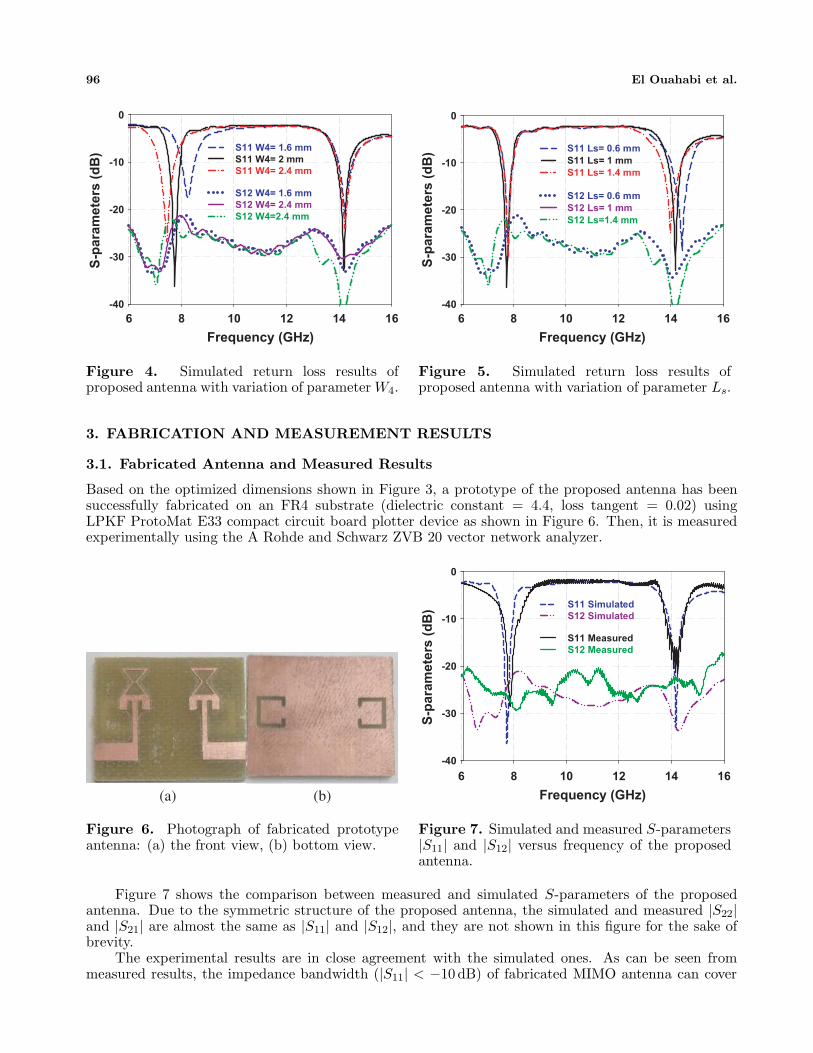
Based on the optimized dimensions shown in Figure 3, a prototype of the proposed antenna has beensuccessfully fabricated on an FR4 substrate (dielectric constant = 4.4, loss tangent = 0.02) usingLPKF ProtoMat E33 compact circuit board plotter device as shown in Figure 6. Then, it is measuredexperimentally using the A Rohde and Schwarz ZVB 20 vector network analyzer.
(a) (b)
Figure 6. Photograph of fabricated prototypeantenna: (a) the front view, (b) bottom view.
Frequency (GHz)
6 8 10 12 14 16
S-p
ara
mete
rs (
dB
)
-40
-30
-20
-10
0
S11 Simulated
S12 Simulated
S11 Measured
S12 Measured
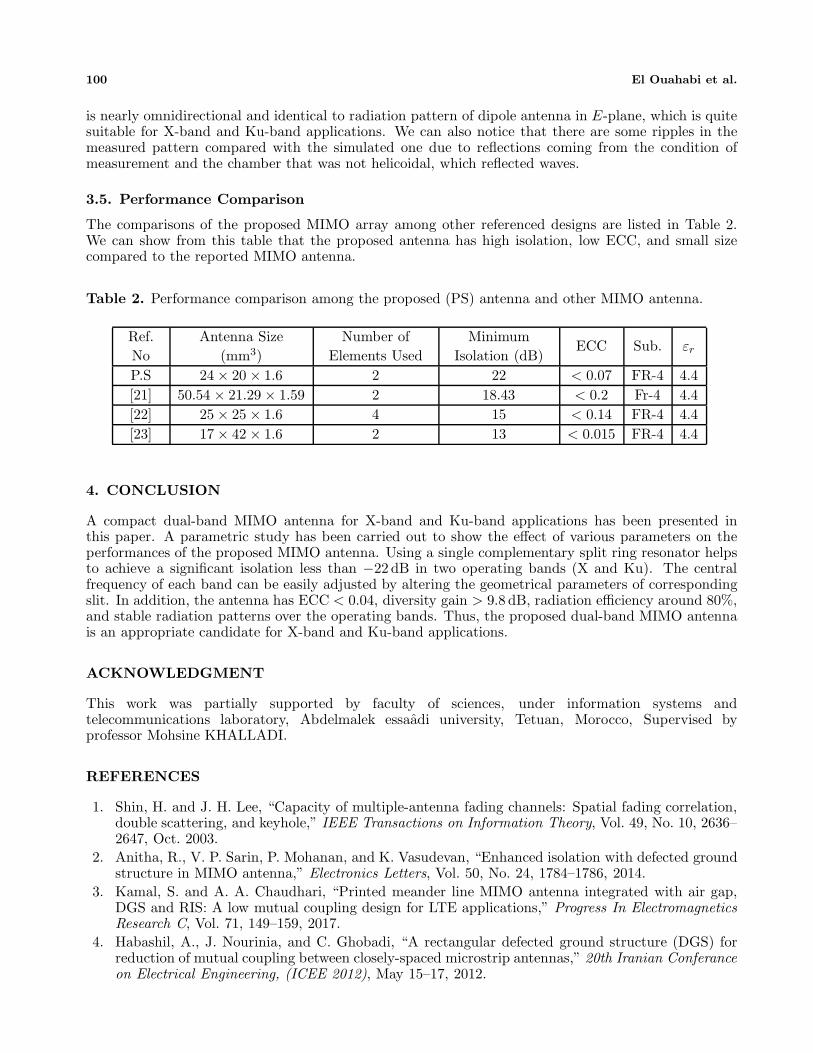
Figure 7. Simulated and measured S-parameters|S11| and |S12| versus frequency of the proposedantenna.
Figure 7 shows the comparison between measured and simulated S-parameters of the proposedantenna. Due to the symmetric structure of the proposed antenna, the simulated and measured |S22|and |S21| are almost the same as |S11| and |S12|, and they are not shown in this figure for the sake ofbrevity.
The experimental results are in close agreement with the simulated ones. As can be seen frommeasured results, the impedance bandwidth (|S11| < −10 dB) of fabricated MIMO antenna can cover

Progress In Electromagnetics Research C, Vol. 93, 2019 97
the lower frequency band 7.6–8.16 GHz (X-band) with the maximum value of 28 dB at 7.83 GHz, andin the higher frequency band 13.8–14.4 GHz (Ku-band) with the maximum value of 20 dB at 14.2 GHz.In addition, along the frequency range, the measured isolation values between ports over the operatingbands are less than −26 and −22 dB, respectively. This indicates a high isolation for the proposeddual-band MIMO antenna.
3.2. Diversity Performance
This section presents an analysis of diversity performance of proposed MIMO antenna in terms ofenvelope correlation coefficient, diversity gain, and radiation efficiency.
The envelope correlation coefficient is an important metric to study MIMO antenna systems andcan be computed using the far-field patterns described in detail in [18]. The correlation coefficientECC(i,j), between the ith and jth antenna elements is calculated and put as the following formula:
ECC(i, j)=
(∮ (XPREθi(Ω)E∗
θj(Ω)Pθ(Ω) + Eϕi(Ω)E∗ϕj(Ω)Pϕ(Ω)
)d(Ω)
)2
∮(XPRGθi(Ω)Pθ(Ω)+Gϕi(Ω)Pϕ(Ω)) d(Ω)·
∮(XPRGθj(Ω)Pθ(Ω)+Gϕj(Ω)Pϕ(Ω)) d(Ω)
(1)In the case of uniform multipath environment, Equation (2) can now be expressed as the envelopecorrelation coefficient ECC for two antenna elements:
ECC =
(∮ (Eθ1(Ω)E∗
θ2(Ω) + Eϕ1(Ω)E∗ϕ2(Ω)
)d(Ω)
)2
∮(Gθ1(Ω) + Gϕ1(Ω)) d(Ω) ·
∮(Gθ2(Ω) + Gϕ2(Ω)) d(Ω)
(2)
where E1 and E2 are the far-field radiation patterns, generated from ports 1 and 2, respectively.The diversity gain (DG) from ECC [19, 20] can be calculated to evaluate the MIMO antenna
performance by using Equation (3):DG = 10 ×
√1 − |ρ|2 (3)
where ρ is the complex cross correlation coefficient, with
|ρ|2 ≈ ECC (4)
Figure 8. Envelope correlation coefficient and diversity gain of proposed antenna.

98 El Ouahabi et al.
Figure 8 shows the correlation coefficient between the antenna elements of the proposed MIMOantenna system from far-field radiation patterns. We can notice that the maximum values of correlationcoefficient are 0.07 and 0.04 in the region of resonances and within the acceptable limits. According tothe same figure, the diversity gain for both bands is greater than 9.8 dB, which means that the proposedMIMO antenna has a good diversity gain performance.
Frequency (GHz)
6 8 10 12 14 16
Eff
icie
nc
y (
%)
0
20
40
60
80
100
Figure 9. Simulated radiation efficiency of proposed antenna.
Figure 9 shows the simulated radiation efficiency plots of the proposed antenna. The radiationefficiency is around 80% across the operating bands.
3.3. Surface Current Distributions
The surface current distributions of presented MIMO antenna at desired frequency bands 7.8 GHz and14.2 GHz are shown in Figure 10. It can be seen that when port 1 is exited and port 2 terminated witha 50-Ω load, a strong current appears on port 2 around the particular form inside the radiation patchand on the single-CSRR in lower band, whereas for upper band, more surface current is induced in aslit. Thus, both slit and single-CSRR helps to achieve high isolation over the operating dual bands ofthe proposed MIMO antenna. This effect remains the same when port 2 is exited and port 1 terminatedwith a 50-Ω load.
(a) (b)
Figure 10. Surface current distribution at: (a) 7.2 GHz and (b) 14.2 GHz.

Progress In Electromagnetics Research C, Vol. 93, 2019 99
3.4. Radiation Patterns
The simulated and measured radiation patterns of the proposed MIMO antenna at the frequencies of7.8 GHz and 14.2 GHz in the E- and H-planes when port 1 is excited and port 2 terminated with a 50-Ωload are plotted in Figures 11(a) and (b), respectively. Note that the radiation patterns in the H-plane
0
150
180
210
Si
M
0
150
180
210
S
M
-
-
-
-
-
-
-
-3-30-25-20-15-10-5
-
-
-
-
-
-
-
120
240
imulated E-plane
Measured E-plane
--30-25-20-15-10-5
120
0
0
240
Simulated E-plane
Measured E-plane
-40 -35 -30 -25 -20 -15
-40
-35
-30
-25
-20
-15
-10
-5
0
-4035
-40
-35
-30
-25
-20
-15
-10
-5
0
60
90
270
300
-40 -35 -30 -25 -20 -1
-40
-35
-30
-25
-20
-15
-10
-5
0
-40-35
-40
-35
-30
-25
-20
-15
-10
-5
0
60
90
270
300
-10 -5 0
0
30
330
-50
150
180
210
5 -10 -5 0
0
30
330
-0
150
180
210
-40
-35
-30
-25
-20
-15
-10
-5
0
-35-30-25-20-15-10
-40
-35
-30
-25
-20
-15
-10
-5
0
120
240
2
-40
-35
-30
-25
-20
-15
-10
-5
0
-35-30-25-20-15-105
-40
-35
-30
-25
-20
-15
-10
-5
0
120
240
-40 -35 -30 -25 -20 -15 -
0
5
0
5
0
5
0
5
0
-40
0
5
0
5
0
5
0
5
0
60
90
270
300
Simulated
Measured
-40 -35 -30 -25 -20 -15 -1
0
5
0
5
0
5
0
5
0
-40
0
5
0
5
0
5
0
5
0
60
90
270
300
Simulated
Measured
10 -5 0
0
30
330
H-plane
H-plane
10 -5 0
0
30
330
H-plane
H-plane
(a)
(b)
Figure 11. Radiation patterns of proposed antenna E-plane (left) and H-plane (right) at: (a) 7.8 GHz,(b) 14.2 GHz.
100 El Ouahabi et al.
is nearly omnidirectional and identical to radiation pattern of dipole antenna in E-plane, which is quitesuitable for X-band and Ku-band applications. We can also notice that there are some ripples in themeasured pattern compared with the simulated one due to reflections coming from the condition ofmeasurement and the chamber that was not helicoidal, which reflected waves.
3.5. Performance Comparison
The comparisons of the proposed MIMO array among other referenced designs are listed in Table 2.We can show from this table that the proposed antenna has high isolation, low ECC, and small sizecompared to the reported MIMO antenna.
Table 2. Performance comparison among the proposed (PS) antenna and other MIMO antenna.
Ref.No
Antenna Size(mm3)
Number ofElements Used
MinimumIsolation (dB)
ECC Sub. εr
P.S 24 × 20 × 1.6 2 22 < 0.07 FR-4 4.4[21] 50.54 × 21.29 × 1.59 2 18.43 < 0.2 Fr-4 4.4[22] 25 × 25 × 1.6 4 15 < 0.14 FR-4 4.4[23] 17 × 42 × 1.6 2 13 < 0.015 FR-4 4.4
4. CONCLUSION
A compact dual-band MIMO antenna for X-band and Ku-band applications has been presented inthis paper. A parametric study has been carried out to show the effect of various parameters on theperformances of the proposed MIMO antenna. Using a single complementary split ring resonator helpsto achieve a significant isolation less than −22 dB in two operating bands (X and Ku). The centralfrequency of each band can be easily adjusted by altering the geometrical parameters of correspondingslit. In addition, the antenna has ECC < 0.04, diversity gain > 9.8 dB, radiation efficiency around 80%,and stable radiation patterns over the operating bands. Thus, the proposed dual-band MIMO antennais an appropriate candidate for X-band and Ku-band applications.
ACKNOWLEDGMENT
This work was partially supported by faculty of sciences, under information systems andtelecommunications laboratory, Abdelmalek essaadi university, Tetuan, Morocco, Supervised byprofessor Mohsine KHALLADI.
REFERENCES
1. Shin, H. and J. H. Lee, “Capacity of multiple-antenna fading channels: Spatial fading correlation,double scattering, and keyhole,” IEEE Transactions on Information Theory, Vol. 49, No. 10, 2636–2647, Oct. 2003.
2. Anitha, R., V. P. Sarin, P. Mohanan, and K. Vasudevan, “Enhanced isolation with defected groundstructure in MIMO antenna,” Electronics Letters, Vol. 50, No. 24, 1784–1786, 2014.
3. Kamal, S. and A. A. Chaudhari, “Printed meander line MIMO antenna integrated with air gap,DGS and RIS: A low mutual coupling design for LTE applications,” Progress In ElectromagneticsResearch C, Vol. 71, 149–159, 2017.
4. Habashil, A., J. Nourinia, and C. Ghobadi, “A rectangular defected ground structure (DGS) forreduction of mutual coupling between closely-spaced microstrip antennas,” 20th Iranian Conferanceon Electrical Engineering, (ICEE 2012), May 15–17, 2012.

Progress In Electromagnetics Research C, Vol. 93, 2019 101
5. Yang, D. G., D. O. Kim, and C.-Y. Kim, “Design of dual-band MIMO monopole antenna with highisolation using slotted CSSRR for WLAN,” Microw. Opt. Technol. Lett., Vol. 56, 2252–2257, 2014.
6. Iqbal, A., O. A. Saraereh, A. Bouazizi, and A. Basir, “Metamaterial-based highly isolated MIMOantenna for portable wireless applications,” Electronics, Vol. 7, No. 10, 267, Oct. 22, 2018.
7. Arora, C., S. S. Pattnaik, and R. N. Baral, “SRR superstrate for gain and bandwidth enhancementof microstrip patch antenna array,” Progress In Electromagnetics Research B, Vol. 76, 73–85, 2017.
8. Nigam, H. and M. Kumar, “A compact MIMO antenna design for 2.4 GHz ISM band frequencyapplications,” International Journal of Electronics and Computer Science Engineering, 324–331,2014.
9. Kayabasi, A., A. Toktas, E. Yigit, and K. Sabanci, “Triangular quad-port multi-polarized UWBMIMO antenna with enhanced isolation using neutralization ring,” AEU — International Journalof Electronics and Communications, 2017.
10. Zhang, S. and G. F. Pedersen, “Mutual coupling reduction for UWB MIMO antennas with awideband neutralization line,” IEEE Antennas and Wireless Propagation Letters, Vol. 15, 166–169,2016.
11. K. A. I. D. A. Xu and J. Zhu, “Wideband patch antenna using multiple parasitic patches and itsarray application with mutual coupling reduction,” IEEE Access, Vol. 6, 42497–42506, 2018.
12. Jaglan, N., S. D. Gupta, B. K. Kanaujia, S. Srivastava, and E. Thakur, “Triple band notched DG-CEBG structure based UWB MIMO/diversity antenna,” Progress In Electromagnetics Research C,Vol. 80, 21–37, 2018.
13. Kumar, N. and U. Kiran Kommuri, “MIMO antenna mutual coupling reduction for WLAN usingspiro meander line UC-EBG,” Progress In Electromagnetics Research C, Vol. 80, 65–77, 2018.
14. Dabas, T., D. Gangwar, B. K. Kanaujia, and A. K. Gautam, “Mutual coupling reduction betweenelements of UWB MIMO antenna using small size uniplanar EBG exhibiting multiple stop bands,”AEU — International Journal of Electronics and Communications, 2018.
15. Kokkinos, T., E. Liakou, and A. P. Feresidis, “Decoupling antenna elements of PIFA arrays onhandheld device,” Electronics Letters, Vol. 44, No. 25, 1442–1444, 2008.
16. Azarm, B., J. Nourinia, C. Ghobadi, M. Majidzadeh, and N. Hatami, “On development of a MIMOantenna for coupling reduction and WiMAX suppression purposes,” AEU — Int. J. Electron.Commun., Vol. 99, 226–235, 2018.
17. Pandit, S., A. Mohan, and P. Ray, “A compact planar MIMO monopole antenna with reducedmutual coupling for WLAN applications using ELC resonator,” Proceedings of the Asia-PacificMicrowave Conference, 2016.
18. Zhang, J., J. Ou Yang, K. Z. Zhang, and F. Yang, “A novel dual-band MIMO antenna with lowercorrelation coefficient,” International Journal of Antennas and Propagation, Vol. 2012, 7 pages,Article ID 512975, 2012.
19. Pierce, J. N. and S. Stein, “Multiple diversity with non-independent fading,” Proceedings of theIRE, Vol. 48, 89–104, Jan. 1960.
20. Schwartz, M., W. R. Bennett, and S. Stein, Communication System and Techniques, 470–474,McGraw-Hill, New York, 1965.
21. Satam, V. and S. Nema, “Defected ground structure planar dual element MIMO antenna forwireless and short range RADAR application,” 2015 IEEE Int. Conf. Signal Process. Informatics,Commun. Energy Syst., SPICES 2015, Feb. 2015.
22. Nirdosh, C. M. Tan, and M. R. Tripathy, “A miniaturized T-shaped MIMO antenna for X-bandand Ku-band applications with enhanced radiation efficiency,” 27th Wirel. Opt. Commun. Conf.WOCC, 2018, Vol. 1, 1–5, 2018.
23. Pouyanfar, N., C. Ghobadi, J. Nourinia, K. Pedram, and M. Majidzadeh, “A compact multi-band MIMO antenna with high isolation for C and X bands using defected ground structure,”Radioengineering, Vol. 27, No. 3, 686–693, 2018.