Embed Size (px)
Citation preview

A Light Transport Model for Mitigating Multipath Interference in Time-of-flightSensors
Nikhil Naik1,2 Achuta Kadambi1 Christoph Rhemann2 Shahram Izadi2
Ramesh Raskar1 Sing Bing Kang2
1MIT Media Lab 2Microsoft Research{naik,kadambi,raskar}@mit.edu {chrheman,shahrami,sbkang}@microsoft.com
Abstract
Continuous-wave Time-of-flight (TOF) range imaginghas become a commercially viable technology with manyapplications in computer vision and graphics. However, thedepth images obtained from TOF cameras contain scene de-pendent errors due to multipath interference (MPI). Specifi-cally, MPI occurs when multiple optical reflections return toa single spatial location on the imaging sensor. Many priorapproaches to rectifying MPI rely on sparsity in optical re-flections, which is an extreme simplification. In this paper,we correct MPI by combining the standard measurementsfrom a TOF camera with information from direct and globallight transport. We report results on both simulated exper-iments and physical experiments (using the Kinect sensor).Our results, evaluated against ground truth, demonstrate aquantitative improvement in depth accuracy.
1. Introduction
Time-of-flight (TOF) cameras represent an increasinglypopular method to obtain depth maps at full framerates of30 FPS. The recent release of the TOF-based Kinect sen-sor [47] will result in the wide-spread adaption of TOFcameras for various traditional and non-traditional applica-tions [35, 23, 31, 34, 24, 2, 44] in computer vision, graph-ics and physics. In this paper we restrict our discussion tocontinuous-wave TOF cameras, which calculate depth bymeasuring the phase difference between an emitted and re-ceived optical signal. In Section 3 we provide an overviewof the technology and a more extensive overview can be befound in [7, 21].
Even though TOF cameras represent an attractive tech-nology for generating depth images in real-time, they sufferfrom many sources of error [9]. We focus on perhaps themain source of error: the problem of multi-path interfer-ence (MPI). The MPI problem occurs when multiple reflec-tions of light in a scene return to a single pixel on the cam-
(a) No MPI b) MPI: 2 bounce (c) MPI: Subsurface Scattering
Figure 1. Multipath interference in time of flight cameras. In (a)the typical operation of TOF cameras is shown. A single opticalpath returns to the image sensor. In (b) an indirect bounce frompoint q to p causes two optical paths to return to the image sensor.In (c), subsurface scattering causes many optical paths to return tothe sensor (one possible path is shown).
era sensor. This problem is particularly significant for TOFsensors, where depth calculations assume a single opticalreflection.
Figure 1 illustrates three different measurement scenar-ios for a TOF sensor. In Figure 1a, the standard operationis shown, where a single reflection from point p strikes theimage sensor. Figure 1b and Figure 1c illustrate cases ofMPI where multiple optical reflections strike the imagingsensor. The former considers a simple two-bounce reflec-tion and the latter subsurface scattering, which cannot bedescribed by a discrete model.
Most prior MPI correction algorithms assume sparsity inoptical reflections. Since sparsity is a weak approximationfor the complexity of scattering, the space of sparse solu-tions has, to date, been restricted to toy scenes [3, 10, 8].Other techniques rely on optical computing, which involvessignificant optical and electronic modifications to the cam-era [40, 32].
In this paper we cast the problem of MPI into the realm
1
Paper Multipath Type Solution Type Quantitative Analysis Hardware ModificationsFuchs [11] Continuous Iterative Limited NoneDorrington et al. [8] 2-sparse Iterative Limited Frequency sweepGodbaz et al. [12] 2-sparse Closed-form None Frequency sweepKadambi et al. [32] K-sparse Iterative None Custom codeKirmani et al. [33] K-sparse Iterative Simulations only Frequency sweepFreedman et al. [10] K-sparse Iterative Simulations only NoneJiminez et al. [29] K-sparse Iterative Limited NoneO’Toole et al. [40] Continuous None None ExtensiveGupta et al. [19] Continuous Closed-form Yes ExtensiveThis Paper Continuous Closed-form Yes External projector
Table 1. This paper proposes a closed form approach to correcting multipath, by relying on light transport information.
of direct-global illumination. Recall that direct illumina-tion represents optical paths from source, to scene point tocamera (Figure 1a). In contrast, global illumination repre-sents optical paths that reach the scene point through indi-rect means (Figure 1b and Figure 1c). The crux of this paperis as follows: we develop a closed-form solution that com-bines the measurements from standard TOF sensors withdirect and global radiance maps (cf. Nayar et al. [38]).
1.1. Contributions
Our key contribution is a novel image formation modelfor TOF sensors that incorporates direct-global separationinto phase and amplitude calculations. We use this model tosignificantly reduce errors caused by multipath interference.Another important contribution is our quantitative evalua-tion of the benefit of our technique using ground truth data.
Our approach uses both the direct and global compo-nents of radiance to modify the traditional depth calculationin time of flight sensing. Direct and global components canbe acquired with the use of a projector [38]. For compar-ison, O’Toole et al. [40] use an involved, optical setup tofilter out the scattered radiance. In addition, where mostprevious methods provide limited or no quantitative anal-ysis of their results [11, 12, 32, 40], we report errors forall scenes in the paper by evaluating our technique againstground truth results (e.g., from an accurate laser scanner).
2. Related Work
2.1. Multipath Interference Correction
We summarize the important related publications onMPI correction in table 1. Fuchs [11] and Jiminez et al [29]solve for the MPI-free phase using an optimization prob-lem and a forward model for TOF imaging. Dorrington etal. [8], Godbaz et al. [12] and Kirmani et al. [33] modelMPI using two bounce approximation and propose iterativeor closed form solutions using multiple frequency measure-ments (or ‘frequency sweep’). Bhandari et al. [4, 3] and
Freedman et al. [10] propose iterative solutions for gener-alized MPI using multiple frequency measurements. Thesesolutions based on K-sparse models (table 1) are tied to thesparsity assumption, which leads to errors when scene re-turns are not sparse (e.g., subsurface scattering). Kadambiet al. [32] introduce a ‘coded’ illumination technique forTOF imaging and demonstrate results for MPI correctionon scenes containing translucent objects. This technique,while promising, requires modifications in hardware, andprecludes real-time performance.
We now turn to an emerging research trend, which in-corporates light transport information to correct for MPI.Our work is of this flavor and is closely related to two re-cent papers by O’Toole et al. [40] and Gupta et al. [19].Building on [41], O’Toole et al. [40] propose a hardwaresolution to block the global component of light transportduring the capture process, thus eliminating MPI. O’Toole’soptical computing approach is accurate, but requires exten-sive optical modifications. The work by Gupta et al. [19]centers on a theoretical justification of temporal light trans-port. Specifically, Gupta shows that the global light trans-port vanishes at high frequencies. In related work, Gupta etal. [18, 15] have also tackled the problem of structured lightscanning in presence of global illumination using coded il-lumination patterns. For a more complete overview, we en-courage the reader to review the work by O’Toole et al. andGupta et al.
2.2. Light Transport Acquisition
Since our work ties light transport acquisition to MPIcorrection, we provide a brief overview of this work. Seitzet al. [46] introduced the problem of ‘inverse light trans-port’, where the goal is to decompose an image into asum of n-bounce images. Nayar et al. [38] propose a fastmethod for separating the direct component of light trans-port from the global component using high frequency illu-mination patterns. Ng et al. [39] introduce a stratified lighttransport matrix which allows computation of the inverselight transport using matrix multiplications. Chandraker

et al. [6] treat inverse light transport acquisition as a dualof forward rendering and propose an algorithm that needsonly matrix-vector multiplication. Reddy et al. [45] intro-duce a method to decompose the light transport in a sceneinto direct (zero-th bounce), near- range (subsurface scatter-ing and local inter-reflections) and far- range (diffuse inter-reflections) components. An exciting approach by O’Tooleet al. [42] exploits coaxial optical setups to separate distinctbounces of optical paths.
Light transport has been successfully applied to a vari-ety of practical problems, including rendering of complexphenomena [16, 49, 50], imaging in poor visibility environ-ments [17], and recovery of surface reflectance [26, 35, 28,27]. In addition, light transport techniques have been verysuccessful for the challenging problem of 3-D scanning oftranslucent objects [25, 20] and high quality structured lightscanning [36, 13, 37, 14].
While there are several light transport techniques to con-sider, we incorporate the method by Nayar et al. [38]. Webelieve it remains the simplest method to acquire and sep-arate the direct and global components of light transport;it requires few images (two in theory) and, importantly, nocalibration.
3. Continuous Wave TOF MeasurementsA continuous-wave TOF camera (hereafter, TOF cam-
era) is able to measure the phase delay of optical paths andobtain depth through the following relation:
z =cϕ
4πfM, (1)
where fM is the modulation frequency of the camera and c isthe speed of light. To estimate ϕ with high precision, a TOFcamera contains an active illumination source that is strobedaccording to a periodic illumination signal. In this paper weconsider standard implementations (e.g. MS Kinect) wherethe emitted signal takes the form of a sinusoid
g(t) = cos (fMt) . (2)
Suppose the light is reflected from a scene point p. Then atthe sensor plane, the received optical signal can be writtenas
s(t;p) = αp cos (fMt+ ϕp) + βp, (3)
where αp is the attenuation in the projected radiance and βp
is the intensity of ambient light. Note the time-invariance ofparametersαp, ϕp, and βp—it is assumed that they are con-stant within the exposure time. A TOF camera computes thecross-correlation of the emitted and received signals, whichevaluates to
c(τ ;p) = s(t;p)⊗ g(t) = αp
2cos (fMτ + ϕp)+βp. (4)
Note that the same information from Equation 3—amplitude, phase, and ambient light—is present in thecross-correlation function. However, the cross-correlationequation is in the domain of τ , which is easier to sample (infact, the TOF sensor directly reads c(τ ;p) from the sensor).As our technique does not incorporate spatial parametriza-tion, hereafter we consider c(τ) as the received signal.
In order to recover the phase and amplitude from the re-ceived signal, the “four bucket principle” is typically used(see [8, 3]). In this method, the TOF camera evenly sam-ples c(τ) four times over the length of a period, for instance,τ = [0, π2 , π,
3π2 ]T . Then the calculated phase can be writ-
ten as
ϕ = arctan
(c(τ4)− c(τ2)c(τ1)− c(τ3)
), (5)
and calculated amplitude as
α =1
2
√(c (τ4)− c (τ2))2 − (c (τ1)− c (τ3))2. (6)
This method is a closed-form technique—in the absence offactors such as multipath interference and sensor noise, thecalculated variables ϕ and α are equal to ground truth valuesϕ and α.
4. Multipath Interference
To calculate accurate depth it is necessary to obtain thetime of flight of the direct light path. However, the lightreceived from a TOF sensor is a combination of direct andglobal illumination [38]. Multipath interference refers tothe undesirable mixing of global illumination with direct il-lumination, which, in a TOF camera, causes a deviation inthe measured phase wrt. the direct phase only. We now pro-vide the mathematical intuition behind MPI, starting withthe most general case.
4.1. Generalized MPI
In the presence of global illumination, the received sig-nal includes contributions from illumination reflected frommultiple scene points. Specifically, we denote illuminationthat has reflected from K locations in the scene as a K-bounce sinusoid with phase ϕK and amplitude αK . In thiscontext, the received signal is a composite of multi-bouncesinusoids and can be written as
c(τ) =α0
2cos (fMτ + ϕ0)︸ ︷︷ ︸
Direct Contribution
+
K∑i=1
αi2
cos (fMτ + ϕi)︸ ︷︷ ︸Global Contribution
+β,
(7)where the problem is not constrained to finite-dimensions,i.e., K =∞ is possible. Substituting Equation 7 into Equa-tions 5 and 6 results in the following expressions for the

measured phase and amplitude
ϕ = arctan
(α0 sinϕ0 +
∑Ki=1 αi sinϕi
α0 cosϕ0 +∑Ki=1 αi cosϕi
), (8)
α2 = α20 +
K∑i=1
α2i + 2
K∑i=0
K∑j=0
αiαj cos (ϕi − ϕj)︸ ︷︷ ︸i6=j
. (9)
Not surprisingly, the measured phase ϕ is not equal to thephase contribution from the direct bounce ϕ0. As a result,the measured depth will be distorted.
4.2. Approximating Global Illumination
In this paper, we approximate global illumination usingonly the lowest order, indirect bounce (i.e., K = 1). Thissimplification has been exploited in previous techniques formultipath interference correction (e.g., [11, 8, 12, 33]). Un-der this assumption, the received signal can be modeled as
c(τ) =αD2
cos (fMτ + ϕD)︸ ︷︷ ︸Direct
+αG2
cos (fMτ + ϕG)︸ ︷︷ ︸Approximate Global
+β,
(10)where subscripts D and G explicitly denote parametersof direct and approximate global illumination. The to-tal projected radiance αT is equal to αD + αG, where0 ≤ αD, αG,≤ 1 and the total radiance is equal to unity.
After substituting the measurement from Equation 10into Equations 5 and 6, we obtain
ϕ = arctan
(αD sinϕD + αG sinϕGαD cosϕD + αG cosϕG
), (11)
α2 = α2D + α2
G + 2αDαG cos (ϕD − ϕG) . (12)
4.3. Direct-Global Separation for MPI Correction
Accurately estimating ϕD would make it possible toameliorate MPI and obtain a robust measurement of depth.Recall that the fast method from Nayar et al. [38] can beused to obtain the radiance of direct and global illumination.For instance, in the case of generalized MPI (Section 4.1),direct-global separation allows us to obtain radiance valuesαD and
∑Ki=1 αi. However, these two measurements are
not helpful in the context of general MPI, where Equations 8and 9 consist of 2N+2 variables, of which only α0 is known.
We now turn to the case of approximate global illumi-nation, where we use the lowest-order indirect bounce toapproximate contributions from global illumination. Underthis approximation, direct-global separation returns valuesfor αD and αG. Notice that between Equations 11 and 12there are four variables, two of which are provided by the
RGB TOF IR Source
ProjectorProjector
Kinect
Scene
Kinect
Figure 2. We demonstrate our method with no hardware modifica-tions to the TOF hardware. Our capture setup (left) consists of aKinect One sensor and a DLP Lightcommander Infrared projector.The capture setup is placed ∼1 meter away from the scene (right).
Nayar method. Given that there are two equations and onlytwo unknown variables, the direct phase can be computedin closed-form as:
ϕD = arctan
(αDγ + αG (sin (ϕD − ϕG) + γ cos (ϕD − ϕG))
αD + αG (cos (ϕD − ϕG)− γ sin (ϕD − ϕG))
),
(13)where γ = tan (ϕ). In summary, relaxing the problem tothe second bounce approximation provides a closed-formsolution for ameliorating multipath interference. In the re-mainder of the paper, we evaluate this closed-form correc-tion through simulations and captured data.
5. ImplementationWe first describe our simulation setup, followed by de-
tails on the physical setup.
5.1. Simulations
To perform simulations, we use the time of flight simu-lator described by Gupta et al. [19]. Given certain scene pa-rameters, for instance, camera and scene specifications, thesimulator outputs the raw measurements from a TOF cam-era in the presence of scattering.1 Following from Section3, we obtain four phase samples of the cross-correlation (cf.Equation 4), which are then used to obtain amplitude andphase images, derived using Equations 5 and 6.
Recall that our proposed algorithm requires both the di-rect and global components of light transport. To obtainsuch values in simulation we place constraints on the num-ber of bounces. Specifically, we follow the conventionfrom [19], where direct and global simulations constrain themaximum number of bounces to zero and four, respectively.The ground truth depth map is obtained by applying, in or-der, Equation 5 and then Equation 1, to the measurementsfrom direct illumination only.
To establish the simulated experiments as a reasonableproxy for Kinect measurements, we incorporate the noisemodel described by Hasinoff et al [22]. In particular, we
1Specifically, we use the following camera parameters: a spatial reso-lution of 512×512 pixels, a focal length of 368 pixels and an illuminationfrequency of 120 MHz.
True Shape Measured Shape Corrected Shape Error: Measured
Error = 16.1 mm
Error = 57.3 mm Error = 16.2 mm
Error = 4.8 mm Error = 1.9 mm
Error: Corrected
0 mm
25 mm
Error = 3.3 mm
0 mm
100 mm
0 mm
20 mm
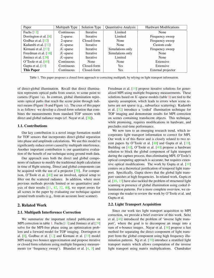
Figure 3. Our MPI correction algorithm reduces the root mean squared error on a variety of objects (simulated experiments). The firstcolumn shows the ground truth point cloud for a given object. The second column depicts the measured point cloud, simulated usingrendering software. The output of our algorithm is shown in the third column. Finally, error comparisons with ground truth are shown inthe fourth and fifth columns.
consider two types of additive noise: (i) scene-dependentshot noise, and (ii) scene-independent read-out noise.
5.2. Physical Implementation
All physical experiments are performed using the Mi-crosoft Kinect One sensor, which provides amplitude andphase measurements (we use a modulation frequency of120 MHz). To separate the direct and global components oflight transport we follow the Nayar method [38], which re-quires high-frequency coded illumination. Instead of mod-ifying the Kinect One to project such patterns, we use anexternal projector. Since the Kinect sensor has an IR-pass,VIS-block filter, we use the DLP Lightcommander projec-tor, which can project patterns at near infrared wavelengths(850 nm).2 Figure 2 summarizes the experimental setup.
We must also remark that the internal light source of theKinect One sensor is much brighter (∼8 times) than the ex-ternal projector. Therefore, it is necessary to perform ra-diometric calibration. To encourage reproducibility, furtherdetails on the capture process (including radiometric cali-bration and details on projected patterns) can be found in
2Projector website: http://www.ti.com/tool/dlplightcommander
supplemental material.
Ground Truth Datasets: A key contribution of this pa-per lies in the evaluation of our technique in the context ofground truth datasets. To capture ground truth for the cornerscene in Figure 4, we use the Kinect sensor to capture eachplanar component of the corner separately. Then, we fit aplane through each point cloud using least-squares, whichare then fused together to obtain the ground truth 3D model.For complex scenes, as in Figure 6, we obtain ground truthby capturing a scan of the object using a multi-stripe, trian-gulation, laser scanner.3
6. Experimental ResultsWe divide our results into simulations and physical ex-
periments. For all scenes, we evaluate our corrected depthmaps using ground truth data. Following standard protocol(e.g., [48]), we report errors using the root-mean-squarederror (RMSE) metric. This metric provides less weight tooutliers.
3Laser Scanner Website: http://www.nextengine.com/assets/pdf/scanner-techspecs.pdf

10 50 90
85
95
105 1
10 50 90
85
95
105
10 50 90
85
95
105
304050607080901
2
3
4
5
6
7
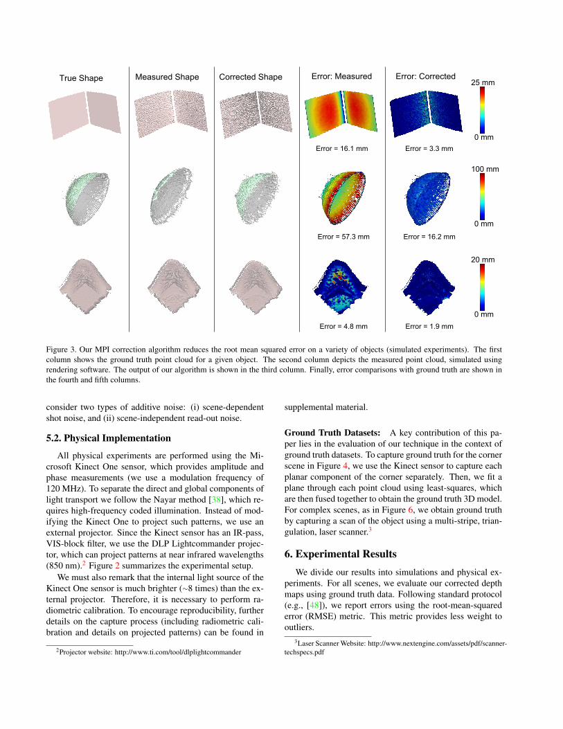
Figure 4. Correcting MPI in scenes with corners (physical experiments). Given an input scene containing a corner, we use the Nayar methodto separate out direct and global components (zoom crop shown). Our correction algorithm shows a reduction in root mean squared errorfor corners of varying angles. For each angle, we plot a cross-section of the reconstruction. The dashed line represents ground truth, whilethe red and magenta lines represent measured and corrected cross-sections.
6.1. Simulations
To validate the algorithm in a controlled setting we per-form simulated experiments. Ground-truth 3-D models—obtained from an online database—are illustrated in the firstcolumn of Figure 3. In particular we select three Lamber-tian objects: a 90 degree corner, a concave bowl, and aneigenfunction of the wave equation (i.e. the Matlab logo).
To obtain the measurements, we use a raytracing ap-proach, as detailed in Section 5.1. The measurementsare shown in the second column of Figure 3, and the er-ror caused by MPI can be observed. In particular, MPIis most significant for the corner and bowl scenes. Bothscenes encourage multipath interference in the form ofinterreflections—between the planes (for the corner) and in-side the concave region (for the bowl). To summarize the3-D measurements: the corner is now rounded, the bowlhas been drastically flattened, and the features of the Mat-lab logo are slightly less distinctive.
The third column of Figure 3 shows the point cloud afterapplying the proposed MPI-correction algorithm. Notably,the corrected corner regains part of its original sharpness,and the bowl returns to its original geometry. Quantitativeresults are shown in the final two columns of Figure 3. Inall cases the corrected RMSE is lower than the measuredRMSE.
The simulated results also reveal a drawback of ourproposed technique: the MPI-corrected results are noisy,jagged, and overall lack the smoothness of the measure-ments (compare columns two and three of Figure 3). How-ever, we believe the MPI-corrected results are preferable.First, the overall error is reduced after MPI correction.Moreover, errors from additive noise can be corrected byusing smoothing filters, already a common element of thedepth sensing pipeline (see supplement for a smoothed re-sult). For comparison, MPI errors cannot be solved by sim-ple filtering (e.g., the bowl in Figure 3).
In summary, the simulated results suggest that a properphysical implementation of our technique should reduce the
RMSE on real scenes.
6.2. Experiments with Real Scenes
The results from physical experiments closely mirror thesimulations, in the sense that the MPI-corrected results re-duce the error in depth maps for each scene we tested. Wenow describe results for three separate scenes that exhibitdifferent forms of MPI. Specifically, this includes MPI frominterreflections, subsurface scattering, and geometric sur-face variations.
Corner Scene: Figure 4 illustrates a simple corner scene,where interreflections contribute to MPI. Following fromour method, we first separate the original scene radianceinto direct and global components. Note that, as expected,the direct component is brightest at the center of the cornerand at the outer edges, which is where the global compo-nent is at a minimum. To make the problem a bit more in-teresting, we apply our correction algorithm on corners withdifferent angles. As illustrated in Figure 4, at all angles, themeasured depth is overestimated and the measured profilelacks sharpness. After applying our correction algorithm,at all angles, we report reduced error in the depth map (seeFigure 4). For all angles, the corrected shape is most accu-rate at the center and the outer edges of the corner, since theglobal component is much weaker as compared to the directcomponent.
Our proposed technique works best on wide corners(with angles greater than 60 degrees). Note that the cornerproblem becomes harder as the angle becomes increasinglyacute due to increasing amounts of global illumination.
Subsurface Scattering Scene: As illustrated in Figure 5,this test scene consists of a block of wax placed in front ofa cardboard background. The wax material exhibits strongsubsurface scattering, and therefore the expected MPI is ofthe form described earlier in Figure 1c. Note that subsurfacemultipath is a continuous phenomena—it is not possible to

100
102
104
106
108
110
DirectWax Scene
Error: 4.25 cm
Pixel Index
Depth
(cm
)
Cross Section
Slice
Global Meas. Depth Corr. Depth
Error: 1.34 cm
Figure 5. MPI-correction reduces error on scenes with subsurface scattering (physical experiment). The original scene (left) consists ofa wax candle. The direct and global components are obtained following the Nayar method. The measured depth of the wax candle isoverestimated due to the subsurface scattering. After applying our correction algorithm, we observe a 70 percent reduction in RMSE error.
provide a finiteK for the number of optical reflections [43].After separation with the Nayar method, we note that (as ex-pected), the wax is significantly brighter than the cardboardin the global image.
After applying our correction technique to the data, weobserve that the measured depth has an RMSE of about 4.25cm, while the corrected depth has an RMSE of about 1.34cm. Note that the error that remains in the corrected depthmap is close to the depth precision of the TOF sensor (thisvalue is about 0.5 cm [30]).
Geometric Scene: We evaluate our method on a plasticfacial mannequin, which exhibits relatively complex geom-etry. The ground truth point cloud—obtained with a laserscanner—is illustrated in Figure 6. Since the face is made ofplastic it lacks significant subsurface scattering. Therefore,we expect that the MPI should arise from concave sectionsin the surface geometry.
The measured shape in Figure 6 exhibits speckle like ar-tifacts, which at first glance look like random noise. How-ever, these artifacts arise because the plastic face has finepits in the surface, which causes similar MPI artifacts tothose observed in the large bowl from Figure 3. After apply-ing our correction technique, the recovered shape is morerepresentative of the surface. Quantitatively, the correctionreduces the RMSE error by 39 percent. After correction,the distribution of residual error is uniform over the surfacegeometry, and at 5.35 mm, the error is very nearly at thedepth precision of the TOF sensor [30].
7. Discussion
In summary, we present a light transport technique tomitigate MPI. Instead of relying on sparsity—an unrealis-tic assumption—we use the data from direct-global separa-tion to recover depth. Our system architecture employs off-the-shelf hardware components, specifically a Kinect and aprojector. For all tested scenes, the corrected point cloudsdemonstrate a reduction in RMSE error.
Ground Truth Shape Error: Measured
Error = 8.71 mm
Error: Corrected
0 mm
25 mm
Error = 5.35 mm
Figure 6. MPI-correction reduces error on scenes with complexgeometry (physical experiment). The original scene consists of aplastic facial mannequin. At (left) is a laser scan of the object,used as ground truth. The measured shape overestimates depth inseveral areas. We observe a 39 percent reduction in RMSE errorafter applying MPI-correction.
Approximating Global Transport: The proposed tech-nique relies on approximating global light transport with thefirst indirect bounce. This is a common simplification thathas been exploited in prior work in light transport (see Bim-ber et al. [5]). Intuitively, the contribution of higher orderbounces rapidly diminishes due to a combination of surfaceabsorbance, the inverse square law, and Lambert’s law (seesupplementary material for details).
Numerical Stability: Our closed form solution for MPIcorrection (Eq. 13) depends on the phase difference be-tween the direct and approximate global bounce i.e (ϕD −ϕG). The scene characteristics and modulation frequencydetermine the amplitude of this term. For low modulationfrequencies, this term can get buried in the noise floor incase of small scenes, thus introducing errors in our cor-rection. In experiments, we observe that our method isrobust to noise at the modulation frequency of 120 MHz.Please see the supplement for the perturbation analysis ofthis problem.
Real-time Performance: Correcting MPI at full framer-ates (i.e. 30 Hz) is not a contribution of this paper. The key
challenge lies in the time required to separate the direct-global components of scene radiance. Specifically, whilethe Nayar method requires, in theory, only two photographs,we must take 25 photographs to compensate for projectorbleed and defocus. In a commercial setting, a more robustimplementation could be achieved by using improved pro-jection systems or incorporating real-time direct-global sep-aration as described in [1].
7.1. Comparisons
Our prototype combines the advantages of a light trans-port based approach with an implementation realized incommodity hardware. For comparison, the novel solu-tion by O’Toole et al. [40] is tied to a particular hard-ware architecture, which is a combination of transient imag-ing hardware, beamsplitters and modified projective optics.The measurement model for transient imaging [32, 23] pre-cludes real-time performance. In contrast, our techniquerelies on the Nayar model of direct-global separation [38],which has been shown—in separate work—to work in real-time [1].
We believe the recent work by Gupta et al. [19] rep-resents a more fair comparison. In their paper they usea slightly modified time of flight sensor to generate dual-frequency measurements. To resolve MPI, they contributenovel theory, which shows that global light transport is neg-ligible at high modulation frequencies. However, for table-top scenes, this vanishing property requires GHz modula-tion frequencies. As a result, their physical experiments areconstrained to large, meter-size scenes. In comparison, ourmethod is not constrained to large scenes or high modula-tion frequencies. We provide results on a variety of objects,including specimens with subsurface scattering or complexgeometry.
7.2. Limitations
Our method reduces error on every tested scene, but can-not be implemented in the Kinect pipeline without intro-ducing additional limitations. In particular, to acquire theglobal and direct components, we use a separate projec-tor, requiring the use of radiometric calibration. Due to thequality of the projector, the we oversample beyond Nayar’stheoretical rule (25 photographs instead of 2). In addition,the FOV of the projector is narrow, at approximately 43 de-grees. Taken together, these three limitations on the projec-tor restrict the current setup to small, static scenes; howeverwe are confident that real-time implementations are possi-ble with improved projective capture setups now availablefor direct-global separation (cf. [1]).
8. Concluding RemarksWe propose a new computational photography tech-
nique to generate higher quality 3-D scans than the stan-
dard Kinect (in the context of RMSE error). By couplinglightweight optical complexity with a closed-form, mathe-matical solution, the proposed technique takes a step towardscalable MPI correction.
Acknowledgments. We would like to thank Philip Chou,Mike Sinclair, Hrvoje Benko and the Microsoft Kinectproduct team for their helpful comments on theory andhardware implementation. We also acknowledge the helpof all the members of the Interactive Visual Media group atMicrosoft Research.
References[1] S. Achar, S. T. Nuske, and S. G. Narasimhan. Compensating
for motion during direct-global separation. 2013. 8[2] A. Bhandari, C. Barsi, R. Whyte, A. Kadambi, A. J. Das,
A. Dorrington, and R. Raskar. Coded time-of-flight imagingfor calibration free fluorescence lifetime estimation. pages2–5, 2014. 1
[3] A. Bhandari, A. Kadambi, R. Whyte, C. Barsi, M. Fei-gin, A. Dorrington, and R. Raskar. Resolving multipathinterference in time-of-flight imaging via modulation fre-quency diversity and sparse regularization. Optics Letters,39(6):1705–1708, 2014. 1, 2, 3
[4] A. Bhandari, A. Kadambi, R. Whyte, L. Streeter, C. Barsi,A. Dorrington, and R. Raskar. Multifrequency time of flightin the context of transient renderings. In ACM SIGGRAPH2013 Posters, page 46. ACM, 2013. 2
[5] O. Bimber, D. Iwai, G. Wetzstein, and A. Grundhofer. Thevisual computing of projector-camera systems. In ComputerGraphics Forum, volume 27, pages 2219–2245, 2008. 7
[6] M. Chandraker, J. Bai, T.-T. Ng, and R. Ramamoorthi. Onthe duality of forward and inverse light transport. IEEETPAMI, 33(10):2122–2128, 2011. 3
[7] C. Dal Mutto, P. Zanuttigh, and G. M. Cortelazzo. Time-of-Flight Cameras and Microsoft Kinect. Springer, 2012. 1
[8] A. A. Dorrington, J. P. Godbaz, M. J. Cree, A. D. Payne,and L. V. Streeter. Separating true range measurements frommulti-path and scattering interference in commercial rangecameras. In IS&T/SPIE Electronic Imaging, pages 786404–786404, 2011. 1, 2, 3, 4
[9] S. Foix, G. Alenya, and C. Torras. Lock-in time-of-flight(tof) cameras: a survey. IEEE Sensors Journal, 2011. 1
[10] D. Freedman, Y. Smolin, E. Krupka, I. Leichter, andM. Schmidt. SRA: Fast removal of general multipath forToF sensors. In ECCV, pages 234–249, 2014. 1, 2
[11] S. Fuchs. Multipath interference compensation in time-of-flight camera images. In ICPR, 2010. 2, 4
[12] J. P. Godbaz, M. J. Cree, and A. A. Dorrington. Closed-forminverses for the mixed pixel/multipath interference problemin amcw lidar. In IS&T/SPIE Electronic Imaging, 2012. 2, 4
[13] J. Gu, T. Kobayashi, M. Gupta, and S. K. Nayar. Multiplexedillumination for scene recovery in the presence of global il-lumination. In ICCV, pages 691–698, 2011. 3
[14] M. Gupta. Shape from scatter. Computer Vision: A ReferenceGuide, pages 721–724, 2014. 3

[15] M. Gupta, A. Agrawal, A. Veeraraghavan, and S. G.Narasimhan. A practical approach to 3d scanning in the pres-ence of interreflections, subsurface scattering and defocus.IJCV, 102(1-3):33–55, 2013. 2
[16] M. Gupta and S. G. Narasimhan. Legendre fluids: aunified framework for analytic reduced space modelingand rendering of participating media. In ACM SIG-GRAPH/Eurographics SCA, 2007. 3
[17] M. Gupta, S. G. Narasimhan, and Y. Y. Schechner. On con-trolling light transport in poor visibility environments. InCVPR, pages 1–8. IEEE, 2008. 3
[18] M. Gupta and S. Nayar. Micro phase shifting. In CVPR,pages 813–820, June 2012. 2
[19] M. Gupta, S. K. Nayar, M. Hullin, and J. Martin. Pha-sor imaging: A generalization of correlation-based time-of-flight imaging. Technical report, Jun 2014. 2, 4, 8
[20] M. Gupta, Q. Yin, and S. K. Nayar. Structured light in sun-light. In ICCV, pages 545–552, 2013. 3
[21] M. Hansard, O. Choi, S. Lee, and R. Horaud. Time-of-FlightCameras. Springer, 2013. 1
[22] S. W. Hasinoff, F. Durand, and W. T. Freeman. Noise-optimal capture for high dynamic range photography. InCVPR, pages 553–560, 2010. 4
[23] F. Heide, M. B. Hullin, J. Gregson, and W. Heidrich. Low-budget transient imaging using photonic mixer devices. ACMTOG, 32(4):45, 2013. 1, 8
[24] F. Heide, L. Xiao, W. Heidrich, and M. B. Hullin. Diffusemirrors: 3d reconstruction from diffuse indirect illuminationusing inexpensive time-of-flight sensors. In CVPR, 2014. 1
[25] M. B. Hullin, M. Fuchs, I. Ihrke, H.-P. Seidel, and H. P.Lensch. Fluorescent immersion range scanning. ACM TOG,27(3):87–87, 2008. 3
[26] M. B. Hullin, J. Hanika, B. Ajdin, H.-P. Seidel, J. Kautz,and H. Lensch. Acquisition and analysis of bispectral bidi-rectional reflectance and reradiation distribution functions.ACM TOG, 29(4):97, 2010. 3
[27] M. B. Hullin, I. Ihrke, W. Heidrich, T. Weyrich, G. Damberg,and M. Fuchs. Computational fabrication and display of ma-terial appearance. In Eurographics State of the Art Reports,pages 137–153, 2012. 3
[28] M. B. Hullin, H. Lensch, R. Raskar, H.-P. Seidel, andI. Ihrke. Dynamic display of brdfs. In Computer GraphicsForum, pages 475–483, 2011. 3
[29] D. Jimenez, D. Pizarro, M. Mazo, and S. Palazuelos. Model-ing and correction of multipath interference in time of flightcameras. Image and Vision Computing, 32(1):1–13, 2014. 2
[30] A. Kadambi, A. Bhandari, and R. Raskar. 3d depth cam-eras in vision: Benefits and limitations of the hardware. InComputer Vision and Machine Learning with RGB-D Sen-sors, pages 3–26. Springer, 2014. 7
[31] A. Kadambi, A. Bhandari, R. Whyte, A. Dorrington, andR. Raskar. Demultiplexing illumination via low cost sens-ing and nanosecond coding. In ICCP, 2014. 1
[32] A. Kadambi, R. Whyte, A. Bhandari, L. Streeter, C. Barsi,A. Dorrington, and R. Raskar. Coded time of flight cameras:sparse deconvolution to address multipath interference andrecover time profiles. ACM TOG, 32(6):167, 2013. 1, 2, 8
[33] A. Kirmani, A. Benedetti, and P. A. Chou. Spumic: Simul-taneous phase unwrapping and multipath interference can-cellation in time-of-flight cameras using spectral methods.In IEEE International Conference on Multimedia and Expo,pages 1–6, 2013. 2, 4
[34] N. Naik, C. Barsi, A. Velten, and R. Raskar. Estimatingwide-angle, spatially varying reflectance using time-resolvedinversion of backscattered light. JOSA A, 31(5):957–963,2014. 1
[35] N. Naik, S. Zhao, A. Velten, R. Raskar, and K. Bala. Sin-gle view reflectance capture using multiplexed scattering andtime-of-flight imaging. In ACM TOG, volume 30, page 171,2011. 1, 3
[36] S. G. Narasimhan, S. K. Nayar, B. Sun, and S. J. Koppal.Structured light in scattering media. In ICCV, pages 420–427, 2005. 3
[37] S. K. Nayar and M. Gupta. Diffuse structured light. In ICCP,pages 1–11. IEEE, 2012. 3
[38] S. K. Nayar, G. Krishnan, M. D. Grossberg, and R. Raskar.Fast separation of direct and global components of a sceneusing high frequency illumination. In ACM TOG, volume 25,pages 935–944. ACM, 2006. 2, 3, 4, 5, 8
[39] T.-T. Ng, R. S. Pahwa, J. Bai, T. Q. Quek, and K.-H. Tan. Ra-diometric compensation using stratified inverses. In ICCV,2009. 2
[40] M. O’Toole, F. Heide, L. Xiao, M. B. Hullin, W. Heidrich,and K. N. Kutulakos. Temporal frequency probing for 5Dtransient analysis of global light transport. ACM TOG, 33(4),2014. 1, 2, 8
[41] M. O’Toole, J. Mather, and K. N. Kutulakos. 3d shape andindirect appearance by structured light transport. In CVPR,2014. 2
[42] M. O’Toole, R. Raskar, and K. N. Kutulakos. Primal-dual coding to probe light transport. ACM Trans. Graph.,31(4):39, 2012. 3
[43] R. Raskar and J. Davis. 5D time-light transport matrix: Whatcan we reason about scene properties. Int. Memo, 2008. 7
[44] D. Raviv, C. Barsi, N. Naik, M. Feigin, and R. Raskar. Poseestimation using time-resolved inversion of diffuse light. Op-tics express, 22(17):20164–20176, 2014. 1
[45] D. Reddy, R. Ramamoorthi, and B. Curless. Frequency-space decomposition and acquisition of light transport underspatially varying illumination. In ECCV, 2012. 3
[46] S. M. Seitz, Y. Matsushita, and K. N. Kutulakos. A theory ofinverse light transport. In ICCV, 2005. 2
[47] J. Sell and P. O’Connor. The xbox one system on a chip andkinect sensor. IEEE Micro, 34(2):44–53, Mar 2014. 1
[48] T. Weise, H. Li, L. Van Gool, and M. Pauly. Face/off: Livefacial puppetry. In ACM SIGGRAPH/Eurographics SCA,pages 7–16. ACM, 2009. 5
[49] D. Wu, G. Wetzstein, C. Barsi, T. Willwacher, M. OToole,N. Naik, Q. Dai, K. Kutulakos, and R. Raskar. Frequencyanalysis of transient light transport with applications in baresensor imaging. In ECCV, pages 542–555. 2012. 3
[50] L.-Q. Yan, M. Hasan, W. Jakob, J. Lawrence, S. Marschner,and R. Ramamoorthi. Rendering glints on high-resolutionnormal-mapped specular surfaces. ACM TOG, 33(4):116,2014. 3