Embed Size (px)
Citation preview

A High-Performance Two-Phase Multipath Scheme forData-Center Networks
Lyno Henrique G. Ferraza,c,1, Rafael Lauferb, Otto Carlos M. B. Duartea, GuyPujollec
aUniversidade Federal do Rio de Janeiro - GTA/POLI-COPPE/UFRJRio de Janeiro, Brazil
b Bell Labs, Alcatel-LucentHolmdel, USA
cLaboratoire d’Informatique de Paris 6 - Sorbonne Universities, UPMC Univ Paris 06Paris, France
Abstract
Multipath forwarding has been recently proposed to improve utilization indata centers by leveraging its redundant network design. However, most mul-tipath proposals require significant modifications to the tenants’ network stackand therefore are only feasible in private clouds. In this paper, we proposea multipath packet-forwarding scheme for public clouds that does not requireany modifications to the tenants’ network stack. Our Two-Phase Multipath(TPM) forwarding scheme is composed of a smart offline configuration phasethat discover optimal disjoint paths and a fast online path selection phase thatimproves flow throughput at run time. A logically centralized manager uses agenetic algorithm to generate and install paths during multipath configuration,and a local controller performs the multipath selection based on network usage.We analyze TPM for different workloads and topologies under several scenariosof usage database location and update policy, and show that it yields up to 77%throughput gains over traditional approaches.
Keywords:Multipathing, Cloud, Data-Center, SDN
1. Introduction
In cloud computing, data centers share their infrastructure with several ten-ants having distinct application requirements [1]. This application diversity
Email addresses: [email protected] (Lyno Henrique G. Ferraz),[email protected] (Rafael Laufer), [email protected] (Otto Carlos M. B.Duarte), [email protected] (Guy Pujolle)
1Grupo de Teleinformatica e Automacao - GTA Universidade Federal do Rio de Janeiro(UFRJ) P.O. Box: 68504 - ZIP Code 21945-972, Ilha do Fundao, Rio de Janeiro, RJ, Brasilphone: +55 21 2562-8635
Preprint submitted to Computer Networks August 24, 2015
within data centers leads to multiple challenges for network design in termsof volume, predictability, and utilization. First, traffic between Top-of-Rack(ToR) switches is currently estimated to be 4x higher than incoming/outgoingtraffic [2]. This high traffic volume requires specific network topologies for datacenters in order to guarantee full bisection bandwidth and to provide fault tol-erance [2, 3, 4, 5]. Second, the random arrival and departure of virtual machinesfrom multiple tenants result in an unpredictable traffic workload, making it hardto provide manual solutions for traffic management. Therefore, automated so-lutions that respond quickly to changes are required to efficiently allocate thenetwork resources. Finally, in order to avoid forwarding loops, legacy networkprotocols, such as the Spanning Tree Protocol (STP) [6], are usually employedto disable certain network links. This ensures that every pair of ToR switchescommunicates over a single path and that the network is loop-free; however, italso restricts the switches from taking advantage of the multiple available pathsin data center topologies.
Whereas volume and predictability are inherent to the traffic nature of theapplication, network utilization can be significantly improved by multipath for-warding. The idea is to split traffic at flow-level granularity among differentpaths in order to fully utilize the available capacity. Although promising, mostapproaches rely on heavy modifications to the network stack of end hosts,ranging from explicit congestion notification (ECN) [7, 8] to multipath con-gestion control [9]. These modifications are not an issue on private clouds,whose sole purpose is to provide services within a single domain. However, ininfrastructure-as-a-service (IaaS) clouds, in which tenants rent virtual machinesand have complete control of their network stacks [10], these solutions are notfeasible. Therefore, solutions that only enhance the network infrastructure whilenot touching the end hosts are required.
A well-known approach for deploying multipath forwarding without mod-ifying the end host is Equal Cost MultiPath (ECMP), commonly adopted indata-centers [11, 12, 13, 2, 3]. Network switches supporting ECMP find mul-tiple paths with the same cost and apply a hash function to certain fields ofthe packet header in order to find the next hop. ECMP is expected to evenlydistribute the flows among the multiple paths and thus prevent network conges-tion. Nevertheless, since hash-based path selection does not keep track of pathutilization, ECMP commonly causes load imbalances when long-lived flows arepresent on selected paths [14]. Similarly, in Valiant Load-Balancing (VLB), theflow source sends traffic to a random intermediate node which, in turn, forwardsit to the destination. As ECMP, this also achieves uniform flow distribution onpaths; however, due to the stateless selection of the intermediate node, VLBsuffers from the same problems as ECMP.
With these issues in mind, we propose a Two-Phase Multipath (TPM) for-warding scheme with a number of key properties:
• No modifications at end hosts: TPM is an in-network load balancingscheme that does not require modifications to the end hosts. This isrequired in multitenant clouds where the provider does not have any access
2
whatsoever to the tenants’ network stack.
• No modifications in hardware: TPM increases the performance ofthe data center with no hardware modifications and avoids changes tothe infrastructure fabric. In addition, it also requires only a handful ofconfigurable features to keep the implementation cost low.
• Robust to asymmetry and topology: TPM handles path asymmetrydue to link failures and topology design. It can also be deployed in arbi-trary topologies and covers the entire spectrum of data center topologies.
• Incrementally deployable: TPM can be deployed in only part of thedata center, and work with other segments of the data center.
The proposed TPM multipath scheme separates the forwarding function-ality into two distinct phases, namely, multipath configuration and multipathselection.
Multipath configuration is the offline phase that computes the best possiblepaths and configures switches when the network is not yet operational. It createsseveral VLAN trees interconnecting all ToR switches, and therefore the pathselection can be performed by simply tagging packets with the proper VLANID at the outgoing ToR switch. To find these trees, the multipath configurationphase uses network topology information to reduce path lengths and increaselink usage. In particular, we propose and formulate a genetic algorithm to findan optimal set of trees with disjoint links. Multipath selection is the onlinephase that chooses the best path for a new flow. The selection is based on pathutilization in order to select the least used path.
To evaluate TPM, we develop a discrete-event simulator at flow-level gran-ularity to model the data center. We test several scenarios inspired in realistictraffic workloads [15]. The results show that TPM always performs better thanthe traditional forwarding schemes with gains up to 77%.
The rest of the paper is structured as follow. Section 2 presents the architec-ture of TPM and our design choices. Section 3 describes the offline multipathconfiguration phase and Section 4 presents the online multipath selection phase.We simulate different scenarios and topologies and present the results in Sec-tion 5. We present the related work in Section 6 and conclusions in Section 7.
2. Architecture of the Two-Phase Multipath Scheme
The proposed Two-Phase Multipath (TPM) scheme explores the path diver-sity of the network to load balance flows using an in-network approach, withoutrequiring any modification to the tenants’ protocol stack. As previously ex-plained, this is performed in two phases: The multipath configuration phaseand the multipath selection phase.
TPM requires two types of devices to manage the entire network: a globallogically centralized manager responsible for the multipath configuration phase,and local controllers responsible for the multipath selection phase. In essence,
3
the global manager collects network topology information, calculates the avail-able paths, and sends them to the network devices to be used later during onlinepath selection. The path computation is performed before the network be-comes operational and also upon any topology change. To obtain the topology,the global manager may use either the Simple Network Management Protocol(SNMP) for topology discovery [16] or OpenFlow [17]. The VLAN for eachtree can also be configured using either approach, which guarantees that mostcommercial off-the-shelf (COTS) devices are suitable to be used with TPM.
In order to exploit multiple paths without having to modify the networkcore, TPM uses VLANs (IEEE 802.1Q). Each VLAN uses a subset of aggrega-tion/core switches to interconnect all ToR switches in a tree topology.
Instead of assigning a VLAN to each path, TPM uses a VLAN for eachtree in order to aggregate multiple paths into a single VLAN ID, thus savingprecious VLAN ID space (each VLAN ID has only 12 bits). Assuming a datacenter with n ToR switches, each tree contains n(n − 1)/2 symmetric paths;our approach is then able to support up to n(n− 1)211 different paths betweenevery pair of ToR switches. This increases the path availability by a factor ofat least n(n − 1)/2 when compared to the case of using a VLAN per path. Inaddition to increasing path availability, VLAN trees do not require a routingprotocol, since there is only a single path between any pair of ToR switches ineach VLAN.
The trees of each VLAN are not entirely disjoint, and thus each link maybelong to multiple trees. During the multipath configuration phase, however,the trees are selected to be as disjoint as possible in order to ensure maximumpath availability between any pair of ToR switches. To find these trees, wepropose a genetic algorithm in Section 3.
We assume that each physical machine in a rack has a virtual switch [18]connected to the same local controller. During packet forwarding, the virtualswitch inserts a VLAN tag into each outgoing packet and also removes theVLAN tag from each incoming packet. Upon arrival of a new outgoing flow,the virtual switch contacts the controller to select an available path for it. Thecontroller then queries a database with network usage information to determinethe least congested path for the new flow, as explained later in Section 4. Oncethe path (and its corresponding VLAN) is selected, the local controller installsan OpenFlow rule on the virtual switch to handle future packets of this flow.Each subsequent packet then receives the assigned VLAN tag and does notrequire contacting the local controller again.
Since the VLAN tag insertion/removal is performed at the edge by virtualswitches, the ToR, aggregation, and core switches are oblivious to the existenceof TPM and only forward packets based on their respective VLAN tag and des-tination MAC address. This design choice allows TPM to be backwards com-patible with existing data center infrastructure and reduce its adoption costs.Additionally, TPM can also be incrementally deployed. All devices run thedefault STP protocol to create a single untagged tree to ensure the intercon-nection of all ToR switches, and therefore of all physical machines. In order tosend packets to devices that do not support TPM, the controller instructs the
4
virtual switches to not insert a VLAN tag into these packets.
3. Multipath Configuration
The multipath configuration phase is responsible for calculating and in-stalling the VLAN trees in the network devices. The challenge here is to provideenough path diversity for each pair of ToR switches to improve network utiliza-tion. However, it is not clear how many trees (and therefore paths) TPM shoulduse in total to achieve this. In addition, it is important that the chosen treesbe as disjoint as possible to provide multiple independent paths for each pair ofToR switches.
In this section, we propose a genetic algorithm to find the best tree set usingtwo objective functions. Defining the size of a tree as the number of its nodes,then one objective function minimizes the tree size in order to avoid long paths;and the other minimizes the link reutilization by the trees to create disjoint trees.The algorithm optimize both objective functions considering Pareto dominancegroup and number of individuals in the population. To calculate the trees, theglobal manager first acquires the network topology, runs the proposed geneticalgorithm, and then installs the VLAN trees in the network devices. Theseoperations are performed offline, and at each long-term modification of thenetwork, such as the installation of new devices. Link failures do not triggerthe calculation and installation of new trees; instead, they are detected by localcontrollers that blacklist the affected paths.
Genetic algorithms (GAs) are a stochastic optimal search technique inspiredby the natural selection process during biological evolution. Its methodologyconsists of (i) modeling each feasible solution (i.e., a tree in our case) as anindividual, (ii) selecting an initial random population, (iii) calculating the phe-notype of each individual, (iv) selecting parents according to their phenotype,(v) recombinating the selected parents to form new children, (vi) mutating in-dividuals to form new children, (vii) selecting the best children to survive tothe next generation, and (viii) go to step (iii) and repeat until a good enoughsolution is found [19]. The selection of parents and children forces the GA toprioritize the best solutions. The recombination in step (v) creates new chil-dren taking the qualities of the parents, and the mutation in step (vi) drasticallychanges the individuals to avoid local optima. Next, we describe each of thesesteps in detail.(i) Individual model: In our application, each individual is a tree intercon-necting all ToR switches. More specifically, given the network graph G = (V,E),where V is the set of switches of the network and E is the set of edges, we definethe population as the set P = {I1, I2, . . . , In}, where each individual Ik ⊆ E isa subset of edges interconnecting all ToR switches in a tree topology. We definethe genotype of an individual Ik as an ordered vector sk =
[sk1 sk2 · · · skm
]containing the switches that belong to the tree in Ik. The order of the switchvector sk is important because it is used to find the tree that sk represents, asshowed next.
5

(a) (b) (c)
(d) (e) (f)
Figure 1: The execution of the proposed tree creation procedure to connect all ToR switches.Highlighted nodes and edges are part of the tree. The switch vector s is showed below thegraph. (a) The procedure first picks a random switch forming the first subtree, i.e., s = [s1].(b)–(d) A new random switch is selected and, if it has a link to any switch in s, then thislink and switch are added to the tree, resulting in s = [s1 s2 s5 s6]. (e) If the selected switchhas no link to other switches in s, it forms a new subtree, but it is still added to the switchvector. (f) If the selected switch has links with switches in different subtrees, it connects toall of them to form a larger tree, resulting in s = [s1 s2 s5 s6 s7 s4]. The procedure in (b)–(f)is repeated until all ToR switches are connected in a single tree.
(ii) Initial population: In order to start the genetic algorithm, we need aninitial population P composed of a few trees. Our general strategy to form a treeis starting from a random switch and adding one additional switch at a time.Figure 1 depicts the proposed tree creation procedure. The procedure startswith a random switch, which forms the first subtree, showed in Figure 1(a). Forease of presentation, we drop the superscript index k and represent the switchvector simply as s =
[s1]. Then, we select another switch at random and, if it
has a link to any of the already picked switches, that link is added to the treeand the switch is added to the genotype. Figures 1(b)–1(d) show this process,after which we have s =
[s1 s2 s5 s6
]. If the selected switch has no link
to any of the switches in s, it forms a new subtree, but it is still added tothe genotype, as showed in Figure 1(e) with s =
[s1 s2 s5 s6 s7
]. If the
6
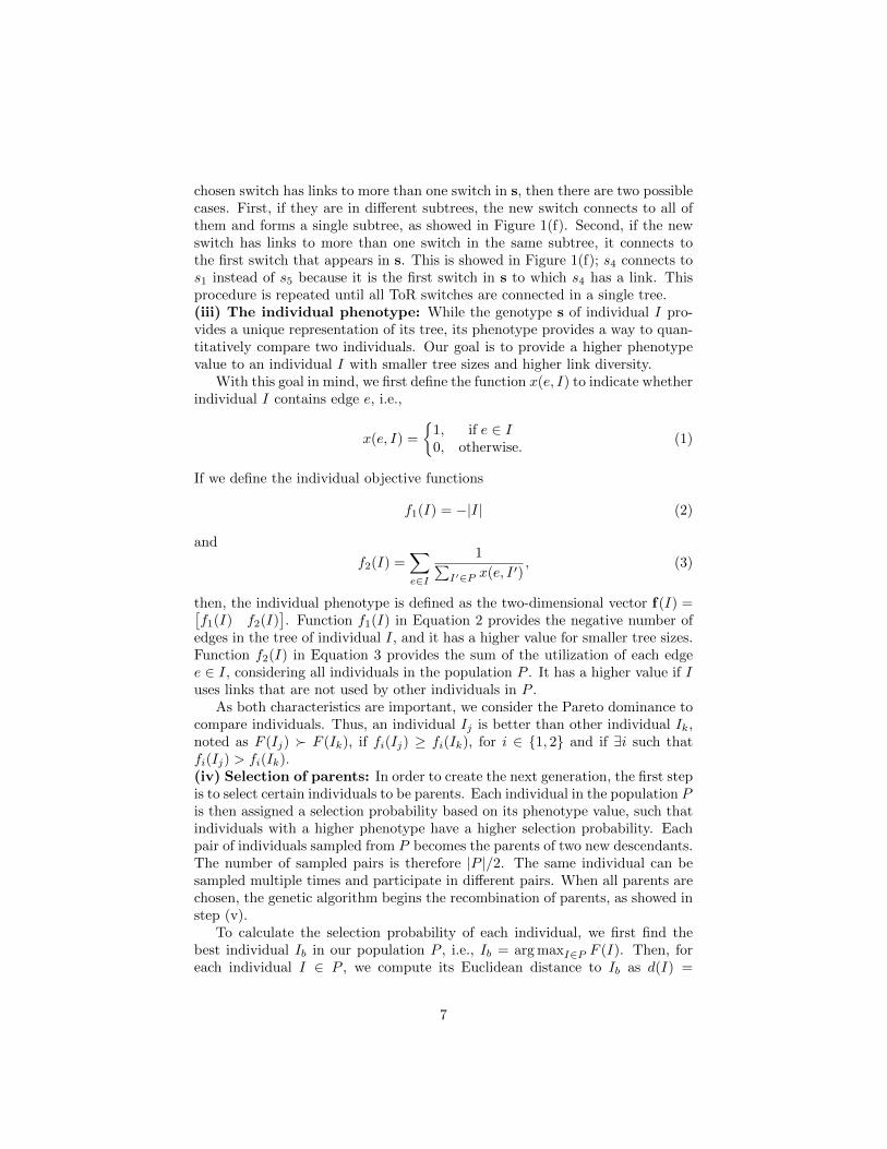
chosen switch has links to more than one switch in s, then there are two possiblecases. First, if they are in different subtrees, the new switch connects to all ofthem and forms a single subtree, as showed in Figure 1(f). Second, if the newswitch has links to more than one switch in the same subtree, it connects tothe first switch that appears in s. This is showed in Figure 1(f); s4 connects tos1 instead of s5 because it is the first switch in s to which s4 has a link. Thisprocedure is repeated until all ToR switches are connected in a single tree.(iii) The individual phenotype: While the genotype s of individual I pro-vides a unique representation of its tree, its phenotype provides a way to quan-titatively compare two individuals. Our goal is to provide a higher phenotypevalue to an individual I with smaller tree sizes and higher link diversity.
With this goal in mind, we first define the function x(e, I) to indicate whetherindividual I contains edge e, i.e.,
x(e, I) =
{1, if e ∈ I0, otherwise.
(1)
If we define the individual objective functions
f1(I) = −|I| (2)
and
f2(I) =∑e∈I
1∑I′∈P x(e, I ′)
, (3)
then, the individual phenotype is defined as the two-dimensional vector f(I) =[f1(I) f2(I)
]. Function f1(I) in Equation 2 provides the negative number of
edges in the tree of individual I, and it has a higher value for smaller tree sizes.Function f2(I) in Equation 3 provides the sum of the utilization of each edgee ∈ I, considering all individuals in the population P . It has a higher value if Iuses links that are not used by other individuals in P .
As both characteristics are important, we consider the Pareto dominance tocompare individuals. Thus, an individual Ij is better than other individual Ik,noted as F (Ij) � F (Ik), if fi(Ij) ≥ fi(Ik), for i ∈ {1, 2} and if ∃i such thatfi(Ij) > fi(Ik).(iv) Selection of parents: In order to create the next generation, the first stepis to select certain individuals to be parents. Each individual in the population Pis then assigned a selection probability based on its phenotype value, such thatindividuals with a higher phenotype have a higher selection probability. Eachpair of individuals sampled from P becomes the parents of two new descendants.The number of sampled pairs is therefore |P |/2. The same individual can besampled multiple times and participate in different pairs. When all parents arechosen, the genetic algorithm begins the recombination of parents, as showed instep (v).
To calculate the selection probability of each individual, we first find thebest individual Ib in our population P , i.e., Ib = arg maxI∈P F (I). Then, foreach individual I ∈ P , we compute its Euclidean distance to Ib as d(I) =
7

‖f(I) − f(Ib)‖. We define the worst individual Iw = arg maxI∈P d(I) as theindividual that is the furthest away from Ib. Since we want nodes closer to Ib tohave a higher chance of being sampled, we define the non-normalized selectionprobability as p(I) = (1 + ε)d(Iw)–d(I), where ε > 0 is a small constant toensure that p(Iw) > 0. Finally, we use p(I) to obtain the normalized selectionprobability p(I) as
p(I) =p(I)∑
I′∈P p(I′). (4)
(v) Recombination of parents: Each pair of parents sampled in step(iv) must be recombined to pass their genotype to two descendants. Letsa =
[a1 a2 · · · am
]and sb =
[b1 b2 · · · bn
]be the genotypes of par-
ents Ia and Ib, respectively. The recombination procedure starts by pick-ing a random position r ∈ [1,min(|Ia|, |Ib|)] of the parents’ genotypes, andsplitting them into a radical and a suffix. Figure 2(a) shows this case forr = 1. The suffixes of the parents are then exchanged, forming two new in-dividuals Iu and Iv, with genotypes su =
[a1 · · · ar br+1 · · · bn
]and
sv =[b1 · · · br ar+1 · · · am
]. These genotypes, however, do not neces-
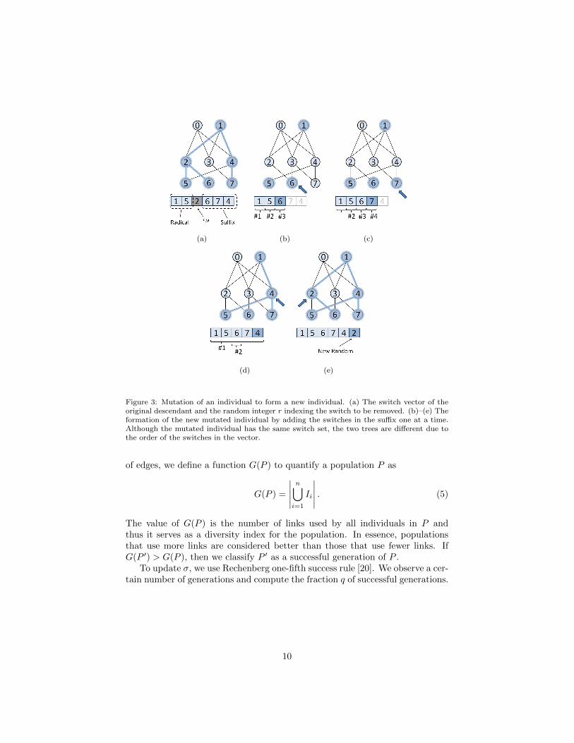
sarily form a tree and thus we run a procedure to ensure the coherence of thedescendents. The procedure is similar to the tree creation procedure in step (ii),but the new switches are selected from the suffix of the other parent. Figure 2shows a step-by-step example of this recombination of two parents to generatetwo descendants. There are only two differences to the previous tree creatingprocedure. First, if a switch in the new suffix is already in the tree, then itis ignored, as showed in Figure 2(d). Second, after processing the new suffix,ToR switches not connected to the tree are added in random order, as showedin Figure 2(f).(vi) Mutation of descendants: After the recombination of parents, eachdescendant may mutate and generate another individual. This occurs withprobability pm = 0.10. The mutation procedure uses the genotype of a descen-dant Iy to generate a mutated individual Iz, such that the genetic algorithmincreases the search space and avoids premature convergence. Similar to therecombination, the mutation procedure samples a random integer r ∈ [1, |Iy|]as an index on the descendant’s genotype sy =
[s1 s2 · · · sm
]. Then, the
switch at that position is removed and the genotype is divided in a radical anda suffix. The resulting genotype is sy =
[s1 s2 · · · sr−1 sr+1 · · · sm
].
As in the recombination procedure, the switches in the suffix are added one attime to form the new mutated individual coherently, and any ToR switch that isnot present in at the end is included in random order. We present the mutationprocedure in Figure 3.(vii) Survivor selection and population size mutation: After the afore-mentioned operations, we have a set of the original individuals, the descendants,and the mutated individuals. It is then required to select which of these individ-uals will survive to the next generation. First, we remove all duplicate individ-uals to ensure that each individual is a different tree. Next, we must determinethe size of the new population, since the optimal size is unknown beforehand.
8

(a) (b) (c)
(d) (e) (f)
Figure 2: Recombination of two parents to generate two descendants. The procedure is similarto the tree creation procedure, except that new switches are selected from the suffix of theother parent. (a) The two trees are showed with their respective genotypes. The randominteger r = 1 is selected and separates the genotypes in radicals and suffixes, which will beexchanged. (b)–(f) The two descendants are generated in parallel. The dark red nodes belongto the first descendant and the light blue nodes belong to second descendant.
We sample the number of individuals of the new population P ′ from a normaldistribution N(|P |, σ) centered in the current population size |P | and havingstandard deviation σ. The result is rounded to the nearest integer. Once thenew population size is determined, then the individuals are ordered accordingto their phenotype and the individuals with the highest phenotype are selectedto survive to the next generation P ′.
After the new generation P ′ is created, we compare it to P to determine ifthe new generation is better. Recalling that each individual I ⊆ E is a subset
9
(a) (b) (c)
(d) (e)
Figure 3: Mutation of an individual to form a new individual. (a) The switch vector of theoriginal descendant and the random integer r indexing the switch to be removed. (b)–(e) Theformation of the new mutated individual by adding the switches in the suffix one at a time.Although the mutated individual has the same switch set, the two trees are different due tothe order of the switches in the vector.
of edges, we define a function G(P ) to quantify a population P as
G(P ) =
∣∣∣∣∣n⋃
i=1
Ii
∣∣∣∣∣ . (5)
The value of G(P ) is the number of links used by all individuals in P andthus it serves as a diversity index for the population. In essence, populationsthat use more links are considered better than those that use fewer links. IfG(P ′) > G(P ), then we classify P ′ as a successful generation of P .
To update σ, we use Rechenberg one-fifth success rule [20]. We observe a cer-tain number of generations and compute the fraction q of successful generations.
10

If c ∈ [0.817, 1] is a constant, then σ is updated as follows
σ =
σ/c, q > 1/5σ · c, q < 1/5σ, q = 1/5.
(6)
The idea behind Rechenberg one-fifth success rule is that, if q is too large, wemay be approaching a local minimum and therefore increasing σ is beneficial toincrease the search space in the population size. Likewise, if q is too low, thesearch space may be too large and we must narrow it down.
4. Multipath Selection
The multipath selection phase occurs online whenever a new flow departsfrom a virtual switch. In this case, the virtual switch contacts its local controllerto assign a path (and therefore a VLAN) to the new flow. All possible VLANtrees are computed and installed during the multipath configuration phase, andare available to each controller. In order to compute the path, the local con-troller accesses a database (cf. Section 4.2) containing the active flows and theircorresponding paths to select a path. Once this is done, the controller installsan OpenFlow rule on the virtual switch in order to tag each outgoing packetof this flow with the assigned VLAN ID. Likewise, another rule is installed tountag each incoming packet of this flow before forwarding them on to the propervirtual machine.
Each local controller manages the flows originated at in a single rack Todetermine when a flow finishes, the local controller frequently queries the flowstatistics of the virtual switches (cf. Section 4.3). To detect and cope withlink and devices failures in paths, the local controller senses when a flow stopsto transmit, which is considered a path failure in that tree and the flow isrescheduled to use a different path.
4.1. Selection Heuristics
To select a path for each new flow, the local controller selects the pathwith the least used links (lul). In order to keep track of link usage, for eachlink e ∈ E, the database stores the link rate r(e) and the number of flowsu(e) concurrently using each link. The link cost is then computed as the ratiou(e)/r(e), such that a link with a higher number of flows and lower rate has ahigher cost. The path cost is then computed as the maximum link cost alongthe path, and the path with the lower cost is selected for a new flow. After theselection, the link usage u(e) for all links in the path are incremented. Similarly,when the flow finishes, all link costs of the path are decremented.
4.2. Database Placement
We consider two extreme cases for the network usage database placement.First, we consider a single global database that is accessed by all local con-trollers. In addition, we also consider each local controller having its own local
11
database to store the link usage of the paths used by its flows. These two cases(i.e., centralized and distributed) are in opposite sides of the spectrum andshould be enough to predict the performance of any hybrid solution, if required.
The global database stores information of all active flows in the network;therefore, local controllers have accurate knowledge of the network congestion.However, this requires that all local controllers frequently query and update thedatabase. If the traffic workload is high, the database would have to answerqueries and update entries at a high rate, which could thwart the task or wouldrequire an elastic data store to keep up with the query/update rate. In addition,all local controllers must communicate with the central database, which mayhave a high overhead depending the query/update frequency. On the otherhand, if the database is local and co-located with the local controller, then allcommunication remain local. Nevertheless, the database does not have globalknowledge of the network usage and may assume that a path is free when infact it is not due to the limited visibility.
4.3. Flow Tracking Policy
As link costs are used for the path selection, the cost information shouldbe up-to-date to prevent avoidable collisions. Hence, in addition to updatingthe costs when a flow starts, it is also important to update them when a flowfinishes in order to free network resources for new flows. The aforementionedheuristics determines when the flow finishes at the cost of the local controllerconstantly monitoring the flows. To loosen this requirement, we propose a fewalternative policies to update the link costs when a flow ends.
In the first policy, the link costs are updated immediately when the flowends (dec-end). This approach can be implemented using notifications fromthe virtual switches to their local controllers. We consider this approach as aguideline.
The second policy simply does not update the costs when the flows end (no-end). Although simplistic, this approach has some knowledge of the congestion,because it accumulates the information selection of paths over time.
The third policy schedules a timeout when the flow starts, regardless of theactual flow duration (scheduled fixed end – sfe). This approach sets a durationfor each flow and decrements its cost regardless of the actual flow duration.Therefore, it does not require tracking of each of the existing flows. Nevertheless,it must estimate the duration of the flows a priori. In our simulations, we usea fixed end timeout value for all flows.
Finally, the last policy periodically monitors the virtual switches in serversto get the number of active flows (periodic monitoring – pm). This approachrequires the local controller to constantly monitor the virtual switches, whichcan be costly.
5. Simulations Results
The simulations compare the well-known multipath schemes Spanning TreeProtocol (stp) and Equal Cost MultiPath (ecmp) with the proposed Two-Phase
12

Multipath (tpm) forwarding scheme.
5.1. Simulation Model
In the simulations, all servers send and receive flows through a ToR switch.Thus, we only consider ToR switches as source and destination, since the pathfrom the ToR switch to the physical machine is unique. We compute the flowtransmission rate at a given time as the fair share of the most contended tra-versed link using a max-min fairness algorithm, which is an optimistic flowmodel, i.e., it assumes flows immediately increase/decrease their rate due to thearrival/departure of other flows in the path.
The workload model consists of two random variables, the flow size Xs
and the flow inter-arrival interval Xt. Larger flows require a longer timeto be transmitted and, thus, they have a higher probability of sharing thelink bandwidth with other flows. The flow size Xs follows a lognormal dis-tribution lnN(µs, σs). We choose µs = 7 and σs = 2.8, such that thecumulative density function (CDF) presents the following values F (x) ={≈ 0.5|x = 1000,≈ 0.95|x = 100000}, according to empirical data center mea-sures published by Benson et al. [15]. The second random variable characteriz-ing the workload, the inter-arrival time Xt, directly affects the data center load.Smaller inter-arrival times increase the flow arrival rate and, consequently, in-crease the network link usage. The inter-arrival time (in microseconds) alsofollows a lognormal distribution lnN(µt, σt) with σt = 2 and µt varying todecrease the workload. We chose different values for µt in order to have the me-dian ta within the set {1, 2, 5, 10, 15, 20, 30}, in milliseconds. We use the medianinstead of the mean to avoid dependency on the standard deviation σt. Theinter-arrival time forms a heavy tailed distribution, and the ta values are chosento have a similar distribution to the empirical measures of [15]. As ta increases,the expected time between flow arrivals also increases and the load decreases.
We compare our proposed scheme with the Spanning Tree Protocol (stp)and with Equal Cost MultiPath (ecmp) forwarding.Spanning Tree Protocol (stp): the switches create a single tree to forwardall traffic. Thus, there is a single path between each pair of ToR switches.Equal Cost MultiPath (ecmp): link state routing protocols identify themultiple paths with the same costs between each pair of ToR switches. Ateach hop, a hash function is applied on certain fields of the packet header touniformly distribute the flows over the paths, and to ensure that all packetsof a flow traverse the same path [12]. We model ECMP as a uniform randomvariable to select paths.
5.2. Fattree 4 Topology
We first run simulations using the Fattree topology with 4r-portswitches [21], which presents four different paths to any ToR switch in any otherpod, and two different paths to a switch in the same pod as depicted in Fig-ure 4. The destinations of the flows are uniformly selected to evenly distributethe traffic across the data center.
13
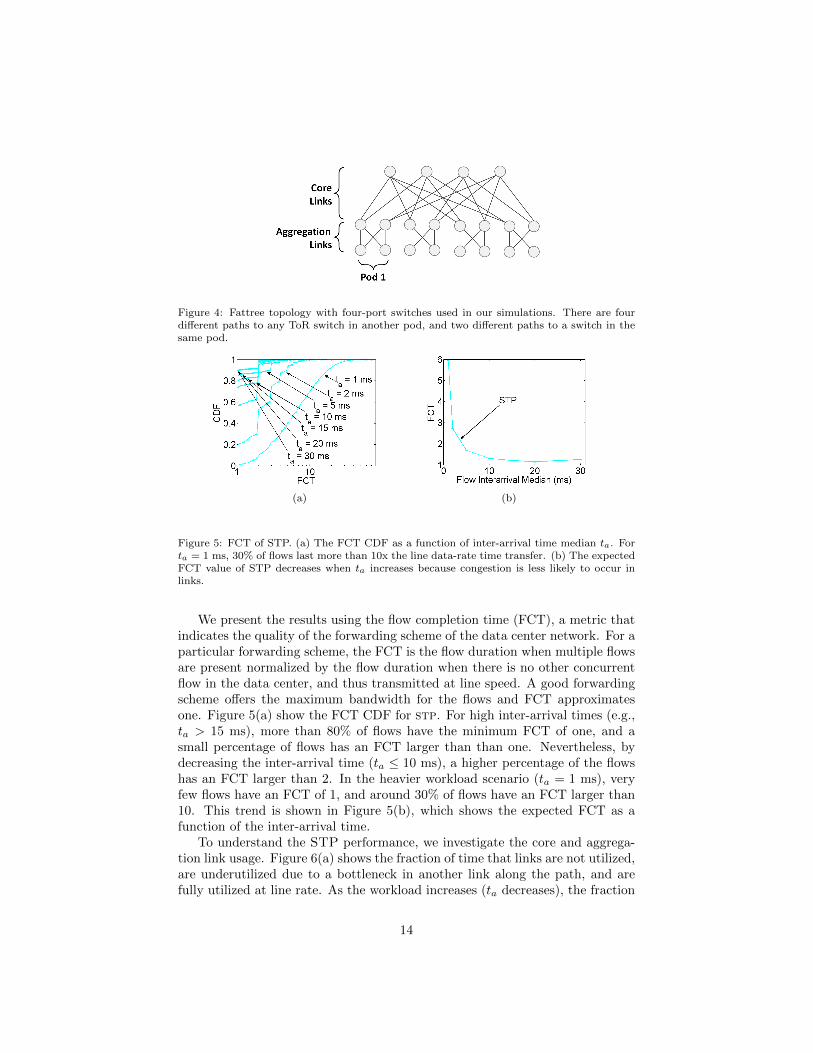
Figure 4: Fattree topology with four-port switches used in our simulations. There are fourdifferent paths to any ToR switch in another pod, and two different paths to a switch in thesame pod.
(a) (b)
Figure 5: FCT of STP. (a) The FCT CDF as a function of inter-arrival time median ta. Forta = 1 ms, 30% of flows last more than 10x the line data-rate time transfer. (b) The expectedFCT value of STP decreases when ta increases because congestion is less likely to occur inlinks.
We present the results using the flow completion time (FCT), a metric thatindicates the quality of the forwarding scheme of the data center network. For aparticular forwarding scheme, the FCT is the flow duration when multiple flowsare present normalized by the flow duration when there is no other concurrentflow in the data center, and thus transmitted at line speed. A good forwardingscheme offers the maximum bandwidth for the flows and FCT approximatesone. Figure 5(a) show the FCT CDF for stp. For high inter-arrival times (e.g.,ta > 15 ms), more than 80% of flows have the minimum FCT of one, and asmall percentage of flows has an FCT larger than than one. Nevertheless, bydecreasing the inter-arrival time (ta ≤ 10 ms), a higher percentage of the flowshas an FCT larger than 2. In the heavier workload scenario (ta = 1 ms), veryfew flows have an FCT of 1, and around 30% of flows have an FCT larger than10. This trend is shown in Figure 5(b), which shows the expected FCT as afunction of the inter-arrival time.
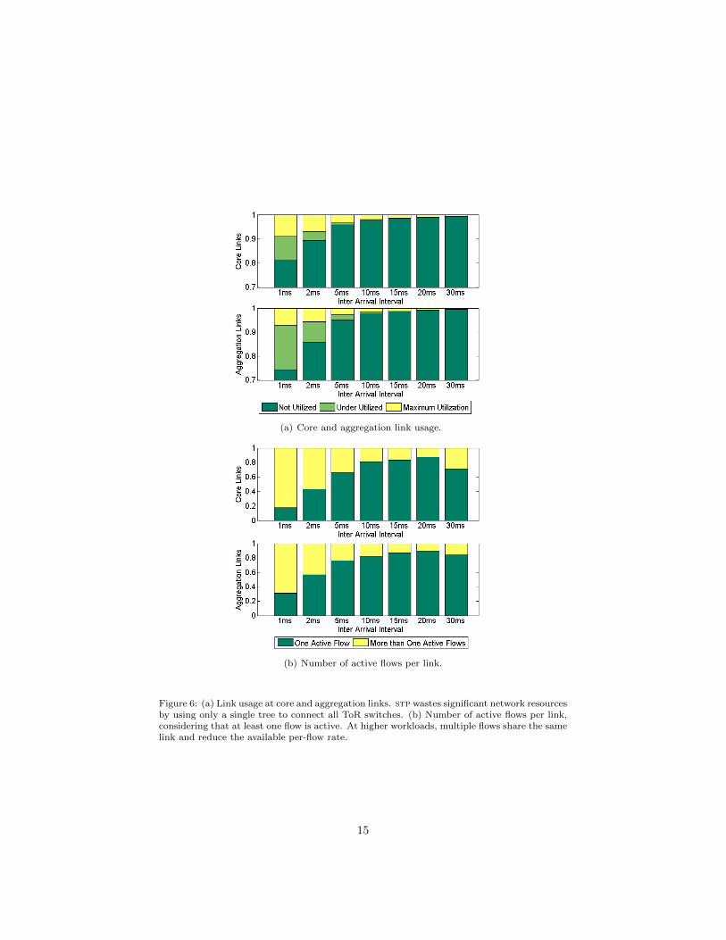
To understand the STP performance, we investigate the core and aggrega-tion link usage. Figure 6(a) shows the fraction of time that links are not utilized,are underutilized due to a bottleneck in another link along the path, and arefully utilized at line rate. As the workload increases (ta decreases), the fraction
14
(a) Core and aggregation link usage.
(b) Number of active flows per link.
Figure 6: (a) Link usage at core and aggregation links. stp wastes significant network resourcesby using only a single tree to connect all ToR switches. (b) Number of active flows per link,considering that at least one flow is active. At higher workloads, multiple flows share the samelink and reduce the available per-flow rate.
15

Figure 7: Expected flow completion time under different workload scenarios (ta values) forthe multipath selection heuristics for Spanning Tree Protocol (stp), Equal Cost MultiPathProtocol (ecmp), and the proposed Two-Phase Multipath (tpm) with different heuristics LeastUsed Tree (lut), Least Used Path (lup), and Least Used Links (lul) with global (global)and local (local) database locations for Fattree 4 ports.
of time that links are utilized is greater, but flows cannot exploit the capacityof most links. All flows whose destination is in another pod share the samecore links, and thus we expect that the core links are more heavily used. Weobserve that most of the time, core links are not utilized. As stp uses a singletree to forward traffic, all links not belonging to this tree are free. Moreover,the core links in the tree have active flows only for part of the time; however,the bandwidth sharing is uneven and flows cannot use all available bandwidth.
In addition to low link usage, the high expected flow completion time is alsocaused by the high the number of active flows sharing the same link. We seefrom Figure 6(a) that links have no active flows most of the time, but as theworkload increases (ta decreases), several active flows share the link bandwidthreducing the expected FCT. Figure 6(b) shows the fraction of time that linksare used by a single flow or by more than one flow. For each link, we onlyconsider the time that it has at least one active flow. We see that both coreand aggregation links have more than one flow for more than 20% of the timewhen ta = 10 ms and this is even worse with ta < 10 ms, with a direct impacton FCT.
We now compare the performance of the same Fattree topology for stp,ecmp, and the proposed tpm using the least used links (lul) heuristic forpath selection and local database placement. We also present results using aglobal database placement with entire knowledge of the network just as a per-formance baseline, but do not consider the communication nor the query/updateoverheads of this approach. In addition, we also present results using previouslyproposed path selection heuristics, namely, least used tree (lut) and least used
16

(a) Core and aggregation link usage.
(b) Number of active flows per link.
Figure 8: (a) Link usage at core and aggregation links for stp, ecmp and tpm for both globaland local database placements. (b) Number of active flows per link, considering that at leastone flow is active.
17

path (lup) [1]. In lut, we track the number of flows using each VLAN tree anduse this as the cost of the tree. Every time a path of this tree is selected for anew flow, the tree cost is incremented. Similarly, when a flow finishes, the treecost is decremented. In lup, the number of flows is tracked on a per-path basisinstead of a per-tree basis. Different than the proposed lul heuristic, both lutand lup cannot be applied when links have multiple bit rates because theseheuristics only track the number of flows using the resource (a tree for lut anda path for lup). Therefore, in order to provide a fair comparison, we use in oursimulations the same rate for all links of the data center.
Figure 7 shows the expected FCT for each of the aforementioned techniques.tpm clearly outperforms STP and ECMP by a significant margin, especiallywhen the data center is overloaded. In particular, when ta is 5 ms, tpm-localreduces approximately 11% of the optimal flow completion time when comparedto ecmp and approximately 54% when compared to stp. If the data center hasan even higher load at ta = 1 ms, then tpm-local roughly reduces 31% overecmp and 4.4x over stp. If a global database is used instead, then thesegains are even more pronounced. At ta = 5 ms, tpm-global reduces 20% ofthe optimal flow completion time over ecmp and more than 64% over stp. Inthe highest workload scenario of ta = 1 ms, tpm-global reduces approximately50% over ecmp and 4.6x over stp.
Figure 7 also presents results for different path selection heuristics anddatabase locations. We see that lup is an optimistic approach since it assumesthat all paths are disjoint. However, as this is not the case in data centers, lupsuffers from selecting paths with already congested links. In contrast, lut is apessimistic approach, because it assumes that all flows in a tree share the samelinks. lut achieves reasonable performance, reducing FCT up to 22% of theoptimal flow completion time compared to ecmp. Our lul heuristic, however,presents the most fine-grained knowledge of link usage and it has therefore thebest performance. With regard to database location, both lut and lul benefitfrom the global knowledge, since the local database is unaware of the truepath usage. However, this is not the case for lup, because paths originated bya particular ToR switch are not shared with other switches. Therefore, pathusage information is contained in the local database and a global database doesnot improve much the performance.
To further investigate the performance of the schemes, we again measurethe core and aggregate link usage as well as the number of active flows per link.Figure 8(a) shows the utilization of core and aggregation links for 1 ms ≤ ta ≤10 ms.
Clearly, stp presents the worse performance because it shares a single treefor all flows. Additionally, most links are often underutilized, reducing evenmore the performance. stp core links are highly utilized with more than 25%in the highest workload scenario and become bottlenecks. In contrast, ECMPand TPM use multiple paths for each pair of ToR switches. As a result, thebottleneck becomes the aggregation links because fattree topologies offer lessdisjoint paths to ToR switches in the same pod. Figure 8(b) shows the numberof flows per link, when links are used by one or more flows. The number of active
18

Figure 9: Expected FCT varying the proportion of small and large flows by changing thestandard deviation σs of the lognormal distribution of flow sizes, with µs = 7 and ta = 5 ms.
flows in STP is high due to the limited path diversity, reducing its performance.ecmp randomizes path selection and does not take network usage informationinto account, resulting in path collision even though there are other unloadedpaths available. Similar to ecmp, tpm creates trees that result in the samepaths as ecmp in a Fattree 4 topology. Nevertheless, as tpm has the networkutilization information available during path selection, its performance is highereven with only a local database. In this case, tpm reduces link underutilizationas well as the number of flows sharing the same path.Small and Large Flows Relationship:
The workload used in the simulations so far uses a fixed relationship betweensmall and large flows provided by the parameters µs = 7 and σs = 2.8. Consid-ering flows with less than 100kB as small and flows with more than 10MB aslarge, the percentage of small and large flows in this workload are 94.86% and0.0002%, respectively. To analyze the impact of the percentage of small andlarge flows, we vary σs in the interval [2, 4], which varies the percentage of smallflows from 98.86% to 87.17% and the percentage of large flows from 0.0002%to 1.09%. We keep ta fixed at 5 ms for different σs values to provide the sameload across experiments.
As σs increases, there is more variance on the flow size and therefore wehave more flows sharing the same links, which severely impacts FCT as shownby Figure 9. The FCT can be up 50 times worse due to the long-lived flows.Figure 10 shows both the utilization and the number of flows per aggregationand core link. When σs = 4, approximately 1% of the flows are large, butthis drastically changes the workload traffic. In particular, links are much moreoverloaded and used by several flows most of the time, as shown in Figure 10.Although the relative increase of large to the small degrades the performance,tpm can still improve the performance when compared to ecmp.
5.3. Larger Fattree Topologies
To analyze the performance of larger Fattree topologies, we also provideresults using Fattree topologies using 6- and 8-port switches. The Fattree 6topology is composed of 6 pods, 9 core switches, and 54 servers, while Fattree8 is composed of 8 pods, 16 core switches and 128 servers. Figures 11 and 12
19

(a) Core and aggregation link utilization.
(b) Number of active flows per link.
Figure 10: Core and aggregation link utilization of σs ∈ [2, 4] for ecmp and tpm for bothglobal and local database placements.
20
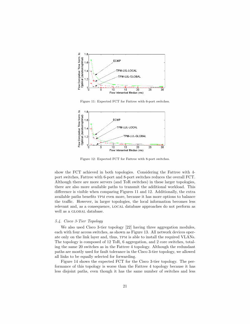
Figure 11: Expected FCT for Fattree with 6-port switches.
Figure 12: Expected FCT for Fattree with 8-port switches.
show the FCT achieved in both topologies. Considering the Fattree with 4-port switches, Fattree with 6-port and 8-port switches reduces the overall FCT.Although there are more servers (and ToR switches) in these larger topologies,there are also more available paths to transmit the additional workload. Thisdifference is visible when comparing Figures 11 and 12. Additionally, the extraavailable paths benefits tpm even more, because it has more options to balancethe traffic. However, in larger topologies, the local information becomes lessrelevant and, as a consequence, local database approaches do not perform aswell as a global database.
5.4. Cisco 3-Tier Topology
We also used Cisco 3-tier topology [22] having three aggregation modules,each with four access switches, as shown as Figure 13. All network devices oper-ate only on the link layer and, thus, tpm is able to install the required VLANs.The topology is composed of 12 ToR, 6 aggregation, and 2 core switches, total-ing the same 20 switches as in the Fattree 4 topology. Although the redundantpaths are mostly used for fault tolerance in the Cisco 3-tier topology, we allowedall links to be equally selected for forwarding.
Figure 14 shows the expected FCT for the Cisco 3-tier topology. The per-formance of this topology is worse than the Fattree 4 topology because it hasless disjoint paths, even though it has the same number of switches and less
21

Figure 13: The Cisco 3-tier topology, composed of the same 20 switches as in the previousFattree 4 topology. The main goal of this topology is the vertical communication.
Figure 14: Expected FCT for the Cisco 3-tier topology. Although under high horizontalcommunication the overall performance degrades when compared to Fattree 4, the topologybenefits by using tpm forwarding scheme.
22

Figure 15: Randomly generated Jellyfish topology with 20 4-port switches. This topology issimilar to the Fattree 4 topology, thus 8 switches are ToR with two servers each.
ToR switches generating traffic. The 3-tier topology main goal is the verticalcommunication, and under high horizontal communication, the overall perfor-mance degrades. Nevertheless, the Cisco 3-tier topology benefits significantlywith tpm, achieving an FCT reduction of 33% under the highest workload whencompared to ecmp.
5.5. Jellyfish Topology
One of the data-center design problems is managing the growth of the in-frastructure to support an increase in demand. Structured data-center designsdo not allow the addition of few devices to supply the increasing demand; in-stead, the addition of an entire overprovisioned new module with several devicesis required. Singla et al. [23] proposed the Jellyfish network topology to allowincremental infrastructure expansions in data centers. Jellyfish is a degree-bounded random regular graph interconnecting the ToR switches. Jellyfish usesa simple iterative procedure to create a sufficiently uniform random regulargraph, solving efficiently a complex graph theory problem. The network is ini-tially assumed to have no links. At each step, a pair of switches with free portsis selected and interconnected, repeating this procedure until no further linkscan be added. If in the end there is still a switch si with more than one freeports, then a random existing link (sj , sk) is removed, and two links (si, sj) and(si, sk) are created instead. Figure 15 shows the Jellyfish topology used in oursimulations, which has eight 4-port ToR switches that use two of those ports toconnect to servers.
Figure 16 shows the expected FCT for the Jellyfish topology. The FCTvalues of all forwarding schemes are higher than both Cisco 3-tier and Fattree4 topology. In particular, this occurs because the generated Jellyfish topologyhas the majority of ToR switches connected to two core switches, but some ToRswitches are directly connected to other ToR switches. Although this benefitsthe communication between the two racks, it degrades the communication with
23
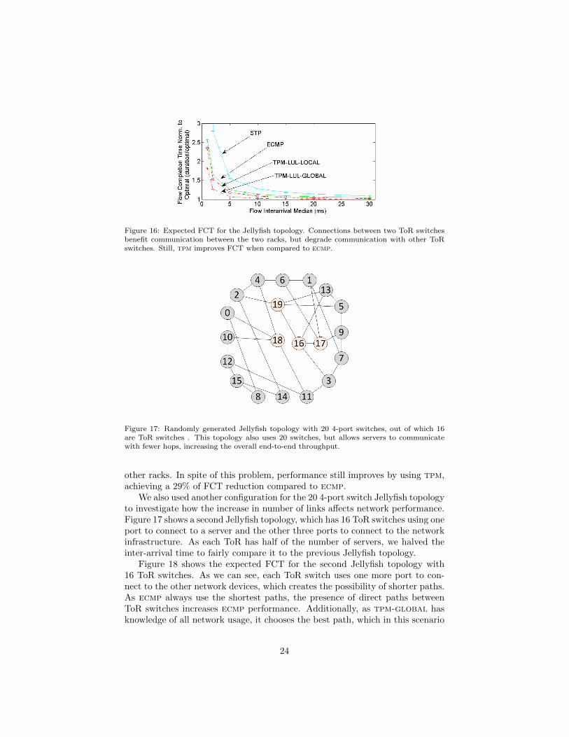
Figure 16: Expected FCT for the Jellyfish topology. Connections between two ToR switchesbenefit communication between the two racks, but degrade communication with other ToRswitches. Still, tpm improves FCT when compared to ecmp.
Figure 17: Randomly generated Jellyfish topology with 20 4-port switches, out of which 16are ToR switches . This topology also uses 20 switches, but allows servers to communicatewith fewer hops, increasing the overall end-to-end throughput.
other racks. In spite of this problem, performance still improves by using tpm,achieving a 29% of FCT reduction compared to ecmp.
We also used another configuration for the 20 4-port switch Jellyfish topologyto investigate how the increase in number of links affects network performance.Figure 17 shows a second Jellyfish topology, which has 16 ToR switches using oneport to connect to a server and the other three ports to connect to the networkinfrastructure. As each ToR has half of the number of servers, we halved theinter-arrival time to fairly compare it to the previous Jellyfish topology.
Figure 18 shows the expected FCT for the second Jellyfish topology with16 ToR switches. As we can see, each ToR switch uses one more port to con-nect to the other network devices, which creates the possibility of shorter paths.As ecmp always use the shortest paths, the presence of direct paths betweenToR switches increases ecmp performance. Additionally, as tpm-global hasknowledge of all network usage, it chooses the best path, which in this scenario
24

Figure 18: Expected FCT for the Jellyfish topology with 16 ToR switches. The presence ofmore ToR ports for communication between other switches improves the overall performance.
presented slightly better results than ecmp. In contrast, the local databasehas little knowledge of the network conditions, and since the several paths usethe outbound paths of other ToR switches, it highly impacts the overall per-formance. Thus, the Jellyfish topology that connects servers within fewer hopsimproves the overall performance.
5.6. Flow Tracking Policy
The path selection for a flow increases the cost of the links along this path.When a flow finishes, it is required to reduce the link costs such that future flowscan properly use the available network resources. We analyze the performanceof four policies to decrease the link cost: (i) immediately when each flow finishes(no special name), (ii) never (noend), (iii) prescheduling a fixed timer for theflows (sfe), and (iv) by periodically monitoring to sense the active flows (pm).We present the simulation results for tpm with both a global and localdatabase
for the highest workload (ta = 1 ms). Figure 19 shows the results of aglobal database. Policy noend does not know when flows end and thus itbalances the traffic by prioritizing paths whose links have been less selected.Policy sfe avoids active monitoring, but the correct tuning of the flow durationis crucial for performance. In the simulations, the flows durations vary fromfew microseconds to several seconds with an expected duration of roughly 1 ms.Thus, the scheduled flow end for 1 ms presents the best performance, but it ismore complex and presents a performance comparable to never decrementingthe costs noend. The pm policy actively monitors the virtual switches, andcan accurately estimate the link usage. As expected, the more frequent themonitoring rate, the better the performance of the selection heuristic.
Figure 20 presents the equivalent results using the proposed local databaseplacement. The results show that a short monitoring period does not providetoo much advantage under the local database placement. In particular, thisoccurs because the information is only local and a higher polling rate is notenough to improve performance. The results are similar to the noend policy.
25
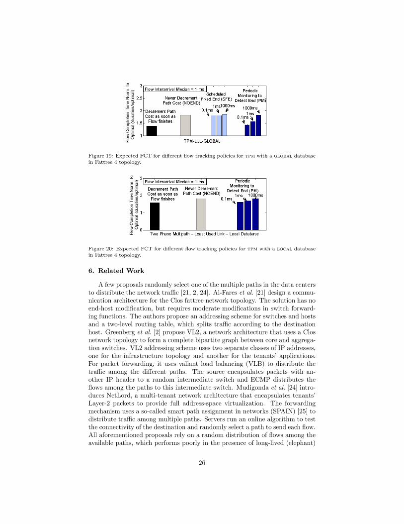
Figure 19: Expected FCT for different flow tracking policies for tpm with a global databasein Fattree 4 topology.
Figure 20: Expected FCT for different flow tracking policies for tpm with a local databasein Fattree 4 topology.
6. Related Work
A few proposals randomly select one of the multiple paths in the data centersto distribute the network traffic [21, 2, 24]. Al-Fares et al. [21] design a commu-nication architecture for the Clos fattree network topology. The solution has noend-host modification, but requires moderate modifications in switch forward-ing functions. The authors propose an addressing scheme for switches and hostsand a two-level routing table, which splits traffic according to the destinationhost. Greenberg et al. [2] propose VL2, a network architecture that uses a Closnetwork topology to form a complete bipartite graph between core and aggrega-tion switches. VL2 addressing scheme uses two separate classes of IP addresses,one for the infrastructure topology and another for the tenants’ applications.For packet forwarding, it uses valiant load balancing (VLB) to distribute thetraffic among the different paths. The source encapsulates packets with an-other IP header to a random intermediate switch and ECMP distributes theflows among the paths to this intermediate switch. Mudigonda et al. [24] intro-duces NetLord, a multi-tenant network architecture that encapsulates tenants’Layer-2 packets to provide full address-space virtualization. The forwardingmechanism uses a so-called smart path assignment in networks (SPAIN) [25] todistribute traffic among multiple paths. Servers run an online algorithm to testthe connectivity of the destination and randomly select a path to send each flow.All aforementioned proposals rely on a random distribution of flows among theavailable paths, which performs poorly in the presence of long-lived (elephant)
26

flows. The proposed TPM scheme avoids that by employing a path selectionheuristic based on link utilization, significantly reducing path selection collisionand improving the overall performance.
Other multipath forwarding schemes were proposed in the context ofsoftware-defined networking (SDN) to manage and distribute data center traf-fic [26]. Al-Fares et al. [11] propose Hedera, a centralized flow scheduling systemthat uses an OpenFlow controller to gather information and manage switches.Hedera uses ECMP to distribute traffic among different paths and monitorstheir duration over time. Hedera detects the presence of long-lived flows andperiodically runs a simulated annealing algorithm to distribute these flows intodifferent paths to maximize transmission rates. In a similar approach, Curtiset al. [27] propose DevoFlow, which devolves the flow management to switcheswhile the controller only keeps track of a few targeted flows. DevoFlow useslocal probability distributions to select the next hop for each flow, and also canuse centralized algorithms to reschedule flow paths as in Hedera. Nevertheless,the centralized algorithms are too slow to optimize the variable data-center traf-fic. Our approach distributes the path selection to the virtual switches at thephysical machines to avoid such constraints.
Alizadeh et al. [14] propose a distributed global congestion-aware balanc-ing (CONGA) mechanism. Each source ToR switch encapsulates the tenants’packets using a VXLAN header, and spine switches update a congestion met-ric field in this header. The destination ToR switch decapsulates the packets,forwards them to the corresponding tenant, and stores the congestion metricof the incoming path. The congestion metric is opportunistically piggybackedin the VXLAN header when the destination ToR switch sends packets back tothe source ToR switch. Thus, ToR switches constantly receive the congestionmetric for each path it sends traffic, and choose the path which minimizes thecongestion metric. Conga utilizes an in-network approach, but it requires sig-nificant modifications to the data-center fabric, which could be costly. Rojas etal. propose All-Path, a routing paradigm that uses reactive approach to learnthe paths in data-center, campus and enterprise networks [28]. Based on thisparadigm, they propose a protocol that learns low-latency paths on-demandbased on broadcasted address resolution protocol (ARP) messages from hosts.Switches broadcast ARP request messages, and they store the port from whichthey received the first copy of the ARP request. The ARP reply follows thelearnt path, allowing switches store the path to the destination. Thus, the ap-proach frequently balances the flows among the low-latency paths. As Conga,All-Path also requires costly modifications on the switches. The proposed tpmscheme can be currently deployed in data centers by only modifying the softwarevirtual switches at the physical machines.
Even though these works contribute to key aspects of multipath forwardingfor cloud computing data centers, we claim that to maintain scalability
, the network infrastructure should be oblivious to the multipath scheme.Hence, both encapsulation mechanism and mapping system are always required.For this purpose, we use VLAN trees, which enable multipath forwarding usingconventional features of commercial off-the-shelf switches. The per-flow man-
27

agement is easily implemented using distributed SDN controllers to manage thevirtual switches at the physical machines.
7. Conclusion
The main goal of the proposed two-phase multipath (tpm) scheme is toimprove the network performance of cloud computing data centers with nomodification to the tenants’ network stack requiring no modifications on thedata-center infrastructure. We improve the network performance using VLANs,which are commonly available in commercial off-the-shelf switches. tpm dividesthe forwarding into two phases: an offline multipath configuration phase thatcalculates available multipaths and install them in the virtual switches, and afast online multipath selection phase to distribute flows among the availablepaths. The multipath configuration is based on a genetic algorithm proposedto find disjoint VLAN trees connecting all ToR switches, and the online multi-path selection phase uses heuristics based on network usage to select the pathfor a new flow. The path selection heuristic may use either a local or a globaldatabase to keep track of link usage. We demonstrate through simulations thatthe proposed tpm scheme has better performance than the conventional equalcost multipath (ecmp) scheme in high workload scenarios. The results showthat the tpm achieves 77% and 27% gains when compared to stp and ecmp,respectively.
Acknowledgments
The authors would like to thank CNPq, CAPES, and FAPERJ for theirfinancial support.
References
[1] L. H. G. Ferraz, D. M. F. Mattos, O. C. M. B. Duarte, A two-phase mul-tipathing scheme based on genetic algorithm for data center networking,IEEE - GLOBECOM 2014 (Dec. 2014).
[2] A. Greenberg, J. R. Hamilton, N. Jain, S. Kandula, C. Kim, P. Lahiri,D. A. Maltz, P. Patel, S. Sengupta, VL2: A scalable and flexible datacenter network 54 (3) (2011) 95–104.
[3] R. Niranjan Mysore, A. Pamboris, N. Farrington, N. Huang, P. Miri,S. Radhakrishnan, V. Subramanya, A. Vahdat, Portland: A scalable fault-tolerant layer 2 data center network fabric, in: Proceedings of the ACMSIGCOMM 2009 Conference on Data Communication, SIGCOMM ’09,ACM, 2009, pp. 39–50.
[4] F. Yao, J. Wu, G. Venkataramani, S. Subramaniam, A comparative analysisof data center network architectures, in: IEEE ICC 2014, 2014, pp. 3106–3111.
28

[5] R. S. Couto, S. Secci, M. E. M. Campista, L. H. M. K. Costa, Latency versussurvivability in geo-distributed data center design, IEEE - GLOBECOM2014 (Dec. 2014).
[6] R. Perlman, An algorithm for distributed computation of a spanningtree inan extended lan, in: ACM SIGCOMM Computer Communication Review,Vol. 15, ACM, 1985, pp. 44–53.
[7] M. Alizadeh, A. Greenberg, D. A. Maltz, J. Padhye, P. Patel, B. Prabhakar,S. Sengupta, M. Sridharan, Data center TCP (DCTCP), in: Proceedingsof ACM SIGCOMM, ACM, 2010, pp. 63–74.
[8] M. Alizadeh, A. Kabbani, T. Edsall, B. Prabhakar, A. Vahdat, M. Yasuda,Less is more: Trading a little bandwidth for ultra-low latency in the datacenter, in: Proceedings of the 9th USENIX NSDI Conference on NSDI,2012, pp. 19–19.
[9] C. Raiciu, S. Barre, C. Pluntke, A. Greenhalgh, D. Wischik, M. Handley,Improving datacenter performance and robustness with multipath TCP,in: Proceedings of ACM SIGCOMM, ACM, 2011, pp. 266–277.
[10] D. M. F. Mattos, O. C. M. B. Duarte, Xenflow: Seamless migration primi-tive and quality of service for virtual networks, IEEE Global Communica-tions Conference - GLOBECOM (Dec. 2014).
[11] M. Al-Fares, S. Radhakrishnan, B. Raghavan, N. Huang, A. Vahdat, Hed-era: Dynamic flow scheduling for data center networks, in: Proceedings ofthe 7th USENIX NSDI Conference on NSDI, USENIX Association, 2010,pp. 19–19.
[12] M. Zhang, A. Ghanwani, V. Manral, A. Banerjee, Transparent Intercon-nection of Lots of Links (TRILL): Clarifications, corrections, and updates,RFC 7180 (Standards Track) (May 2014).
[13] IEEE802.1aq, Standard for local and metropolitan area networks: Virtualbridges and virtual bridged local area networks - amendment 9: Shortestpath bridging (Mar. 2012).
[14] M. Alizadeh, T. Edsall, S. Dharmapurikar, R. Vaidyanathan, K. Chu,A. Fingerhut, V. T. Lam, F. Matus, R. Pan, N. Yadav, G. Varghese,CONGA: Distributed congestion-aware load balancing for datacenters, in:Proceedings of ACM SIGCOMM, 2014, pp. 503–514.
[15] T. Benson, A. Akella, D. A. Maltz, Network traffic characteristics of datacenters in the wild, in: Proceedings of the ACM SIGCOMM IMC, 2010,pp. 267–280.
[16] S. Pandey, M.-J. Choi, Y. J. Won, J. Won-Ki Hong, SNMP-based enterpriseIP network topology discovery, International Journal of Network Manage-ment 21 (3) (2011) 169–184.
29

[17] N. McKeown, T. Anderson, H. Balakrishnan, G. Parulkar, L. Peterson,J. Rexford, S. Shenker, J. Turner, OpenFlow: Enabling innovation in cam-pus networks, SIGCOMM Comput. Commun. Rev. 38 (2) (2008) 69–74.
[18] B. Pfaff, J. Pettit, T. Koponen, K. Amidon, M. Casado, S. Shenker, Ex-tending networking into the virtualization layer, Proc. HotNets.
[19] D. W. Coit, A. E. Smith, Solving the redundancy allocation problem us-ing a combined neural network/genetic algorithm approach, Computers &Operations Research 23 (6) (1996) 515 – 526.
[20] B. Doerr, C. Doerr, Optimal parameter choices through self-adjustment:Applying the 1/5-th rule in discrete settings, GECCO ’15 (to appear),2015.
[21] M. Al-Fares, A. Loukissas, A. Vahdat, A scalable, commodity data centernetwork architecture, in: Proceedings of ACM SIGCOMM, ACM, 2008,pp. 63–74.
[22] A. Headquarters, Cisco Data Center Infrastructure 2.5 Design Guide, CiscoSystems, Inc, 2007.
[23] A. Singla, C.-Y. Hong, L. Popa, P. B. Godfrey, Jellyfish: Networking datacenters randomly, in: Proceedings of the 9th USENIX NSDI Conference onNSDI, NSDI’12, 2012.
[24] J. Mudigonda, P. Yalagandula, J. Mogul, B. Stiekes, Y. Pouffary, NetLord:A scalable multi-tenant network architecture for virtualized datacenters,in: Proceedings of the ACM SIGCOMM 2011 Conference, SIGCOMM ’11,ACM, 2011, pp. 62–73.
[25] J. Mudigonda, P. Yalagandula, M. Al-Fares, J. C. Mogul, SPAIN: COTSdata-center Ethernet for multipathing over arbitrary topologies, in: Pro-ceedings of the 7th USENIX NSDI Conference on NSDI, USENIX Associ-ation, 2010.
[26] A. Hakiri, A. Gokhale, P. Berthou, D. C. Schmidt, T. Gayraud, Software-defined networking: Challenges and research opportunities for future inter-net, Computer Networks 75, Part A (2014) 453 – 471.
[27] A. R. Curtis, J. C. Mogul, J. Tourrilhes, P. Yalagandula, P. Sharma,S. Banerjee, DevoFlow: Scaling flow management for high-performancenetworks, in: Proceedings of the ACM SIGCOMM 2011 Conference, ACM,2011, pp. 254–265.
[28] E. Rojas, G. Ibanez, J. M. Gimenez-Guzman, J. A. Carral, A. Garcia-Martinez, I. Martinez-Yelmo, J. M. Arco, All-path bridging: Path explo-ration protocols for data center and campus networks, Computer Networks79 (2015) 120 – 132.
30