Embed Size (px)
Citation preview

HAL Id: hal-01063310https://hal.archives-ouvertes.fr/hal-01063310
Submitted on 11 Sep 2014
HAL is a multi-disciplinary open accessarchive for the deposit and dissemination of sci-entific research documents, whether they are pub-lished or not. The documents may come fromteaching and research institutions in France orabroad, or from public or private research centers.
L’archive ouverte pluridisciplinaire HAL, estdestinée au dépôt et à la diffusion de documentsscientifiques de niveau recherche, publiés ou non,émanant des établissements d’enseignement et derecherche français ou étrangers, des laboratoirespublics ou privés.
A Conformal/Rollable Monolithic MiniaturizedUltra-Portable Ground Penetrating Radar Using
Additive and Inkjet PrintingAnya Traille, Sangkil Kim, Anthony Coustou, Hervé Aubert, Manos Tentzeris
To cite this version:Anya Traille, Sangkil Kim, Anthony Coustou, Hervé Aubert, Manos Tentzeris. A Conformal/RollableMonolithic Miniaturized Ultra-Portable Ground Penetrating Radar Using Additive and Inkjet Print-ing. International Microwave Symposium, Jun 2014, Tampa Bay, United States. 4p., 2014. <hal-01063310>

A Conformal/Rollable Monolithic Miniaturized Ultra-Portable Ground Penetrating Radar Using Additive and Inkjet Printing
Anya Traille1, Sangkil Kim2, Antony Coustou1, Herve Aubert1, Manos M. Tentzeris2
1University of Toulouse, INP, LAAS-CNRS, 7 Avenue du Colonel Roche, Toulouse, 31400, France 2Georgia Institure of Technology, Atlanta, GA, 30305, USA
[email protected] Abstract — Typical UWB FMCW Ground Penetrating (GPR)
Radars operate at low frequencies that require a wide sweep bandwidth thus necessitating complex architectures and bulky broad-band antennas. This poses unique challenges to the system portability especially for manual, wide-area outdoor measurements. In this paper, we present the first design, fabrication and characterization of a complete conformal and miniaturized radar system to be rolled up in a “poster-like” container using additive printing technology. As the lumped or distributed passives, the active devices and the Rx/Tx antennas may share the same flexible substrate, the proposed radar technology is considered to be monolithic. The presented proof-of-concept system performs the most fundamental operations of the FMCW radar including signal generation, as well as the amplification and correlation of the LO and RF signals for GPR frequencies. Specifically, this paper outlines an ultra low cost system integration, packaging and experimental verification of a flexible/conformal monolithic radar system with almost identical performance for different degrees of flexing.
Index Terms — Monolithic, conformal, FMCW radar, Ground Penetrating Radar, flexible electronics, inkjet printing additive printing.
I. INTRODUCTION
Radar is a very mature and established technology dating back to the 1920s. FMCW (frequency modulated continuous wave) radar, in particular, combines the advantages of the high-resolution impulse radar (ΔR ~ 1/B) and the low power CW (continuous wave) radar (E=Pavτp). Other advantages include high SNR, wide dynamic range, low NF, better angular resolution, cheaper/simple low-power components (Power Amplifier and low speed Analog to Digital Converter), and frequency control/versatility, while its main disadvantages include licensing restrictions, and time gating against reflections and multipath. Both Pulsed and FMCW imaging radars have become popular in ground penetrating radar applications with Pulsed radar being more commercially available and the FMCW radar developed and used mainly by research groups.
Advancements in FMCW radar have been mostly due to major hardware developments, signal processing techniques, waveform design, and system level integration of new components into new architectures, such as the Ultra Wideband FMCW Ground Penetrating Radar (GPR) [1] which is a recently developed technology for high resolution imaging applications such as concealed weapon detection and detailed subsurface imaging. In the case of GPR, the unique challenge
of Ultra wideband FMCW radar is that it requires the use of very low frequencies (<300MHz) to obtain penetration depths of at least several meters (to detect ground water for example) and a very wide sweep bandwidth to achieve submeter resolution for detailed subsurface images [1]. This makes typical GPR systems too bulky for backpack transportation and simple deployment. In addition, GPR, unlike other radar systems must perform manual wide-area measurements commonly using a vehicle, sled or by walking. There is a severe lack of flexible radar platforms providing the mechanical versatility that would facilitate geophysical studies (particularly in rugged environments such as the arctic, desert, uneven mountainous terrains or space).
In this paper we propose the first additive-printing-based packaging process of a conformal, monolithic radar system for a UWB FMCW applications operating in the VHF/UHF range for deep/shallow subsurface imaging. The main challenges of packaging a UWB FMCW radar are due to the facts that: (1) the high percentage bandwidth at low frequencies complicates the pure, linear, and spurious-free signal generation (for example limited availability steep-skirted filters) and the receiver requirements therefore requiring very complex receiver architectures [2] and, (2) at low GPR frequencies, very large broadband antennas are required which are commonly bulky.
Such a challenge can be met only with packaging modifications in both the electronic system and the antenna, where they both get combined into one single flexible, conformal, rollable and robust system using a cost effective approach. To achieve that in this paper we had to address the most current challenges in flexible electronics which are related to fabrication (metal thickness uniformity, flexible interconnects, accurate alignment), performance distortion, robustness (delamination of IC’s) and lifetime (power handling). Flexible PCBs made from flexible polymer do exist however they still require photolithography and lamination fabrication processes [3]. Cost effective inkjet printing of individual components such as passives, interconnects and antennas for sensor modules has been demonstrated in [4], however this is the first reported design and validation of a complete radar system which can be easily extended to multilayer densely interconnected circuits for more complex multi-mode/multi-channel radar architectures for other radar imaging applications and frequencies. The full
system is referred to as monolithic as lumpepassives (hybrid coupler, matching baluns, fiactive devices (VCO, LNA and Power AmRx/Tx antennas may share here the same flexthe proposed radar technology. The following sections will show the deand measurement of the Monolithic FPenetrating Radar and access the challenges ouniformity, IC delamination, alignmentinterconnects. Upon completion, the entire sthe antenna is to be presented at the conferenc
II. MONOLITHIC FMCW RADAR DE
A simple FMCW architecture using operaticustomized for high resolution GPR was implemented in Polyethylene terephthalate proof-of-concept demonstrator. Based on thand required output SNR (as well as other
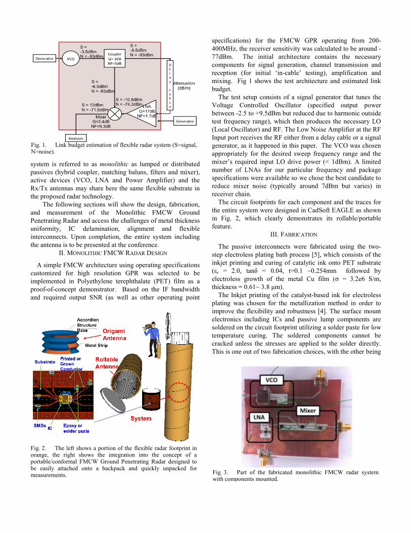
Fig. 1. Link budget estimation of flexible radar N=noise).
Fig. 2. The left shows a portion of the flexible orange, the right shows the integration into thportable/conformal FMCW Ground Penetrating Rbe easily attached onto a backpack and quickmeasurements.
ed or distributed ilters and mixer), mplifier) and the xible substrate in
sign, fabrication, FMCW Ground of metal thickness t and flexible system including ce. ESIGN
ing specifications selected to be
(PET) film as a he IF bandwidth r operating point
specifications) for the FMCW G400MHz, the receiver sensitivity wa77dBm. The initial architecturecomponents for signal generation, reception (for initial ‘in-cable’ temixing. Fig 1 shows the test archbudget.
The test setup consists of a signVoltage Controlled Oscillator between -2.5 to +9.5dBm but reductest frequency range), which then p(Local Oscillator) and RF. The LowInput port receives the RF either frogenerator, as it happened in this papappropriately for the desired sweepmixer’s required input LO drive ponumber of LNAs for our particulspecifications were available so we reduce mixer noise (typically aroreceiver chain.
The circuit footprints for each cothe entire system were designed in in Fig. 2, which clearly demonsfeature.
III. FABRICAT
The passive interconnects were step electroless plating bath processinkjet printing and curing of cataly(εr = 2.0, tanδ = 0.04, t=0.1 ~electroless growth of the metal Cthickness = 0.61~ 3.8 μm).
The Inkjet printing of the catalysplating was chosen for the metalliimprove the flexibility and robustnelectronics including ICs and passsoldered on the circuit footprint utiltemperature curing. The solderedcracked unless the stresses are appThis is one out of two fabrication ch
system (S=signal,
radar footprint in he concept of a
Radar designed to kly unpacked for Fig. 3. Part of the fabricated mono
with components mounted.
GPR operating from 200-as calculated to be around -e contains the necessary
channel transmission and esting), amplification and
hitecture and estimated link
nal generator that tunes the (specified output power
ced due to harmonic outside produces the necessary LO
w Noise Amplifier at the RF om a delay cable or a signal per. The VCO was chosen p frequency range and the ower (< 1dBm). A limited ar frequency and package chose the best candidate to
ound 7dBm but varies) in
omponent and the traces for CadSoft EAGLE as shown
strates its rollable/portable
TION
fabricated using the two-s [5], which consists of the
ytic ink onto PET substrate ~0.254mm followed by Cu film (σ = 3.2e6 S/m,
st-based ink for electroless ization method in order to ess [4]. The surface mount sive lump components are lizing a solder paste for low d components cannot be plied to the solder directly. hoices, with the other being
olithic FMCW radar system

the inkjet printing of a silver nanoparticle ink (σ = 1.1e7 S/m) onto paper, PET or LCP (εr = 3 ~ 3.2, tan δ = 0.02 ~ 0.05, thickness = 0.254 mm) which offers a more expensive but improved electrical properties. The fabricated system is shown in Fig. 3.
IV. MEASUREMENTS
Measurements were performed on the fabricated structure to validate its performance. The signal generated from the Crystek VCO (frequency range of 200 ~ 400 MHz, tuning voltage 0 ~ 5V was tested at the RF output port of the flexible system (Fig. 4).
Due to the absence of a PLL circuit to stabilize the output frequency control phase noise, the VCO needed to be characterized extensively. The VCO output was measured at the RF output port following the hybrid coupler. The full radar system was measured, starting from signal generation all the way to the IF output port (VCO, Hybrid Coupler, LNA and Mixer). The measured IF output frequency (Fig. 5) corresponded exactly to the RF-LO frequency difference s of 22 MHz, 28 MHz and 34 MHz. All components were confirmed to work exactly as specified. The only system weakness observed was the high insertion loss from the mixer. This could be attributed to the matching circuit. The output power level can be improved by adding an external LC matching network such as a T- or –π matching networks at the
output port, as such topologies provide more design versatility than L matching networks. In addition, adjusting the two input power levels (LO and RFin) of the mixer (using attenuators) to be closer together may improve the mixer output signal gain.Due to the absence of a VGA equipped Automatic Gain Control circuit found in many transmitters [1], the normalized output power level changes with frequency.
A. Flexibility Test
A flexibility test was performed in order to benchmark the system performance in a rolled/flexed state. Fig 6 shows the IF output when wrapping the system around a foam cylinder of radius 4.5cm both horizontally and vertically demonstrating an almost flex-independent performance of the radar module. It has to be stressed that output power level (between -70 and -75 dBm in our preliminary experiment) was the same for both rolled and unrolled configurations.
The only parameter limiting the minimum radius of the circuit's bending curvature is limited by the largest surface mount ICs. The largest electronic component of the proposed circuit is the VCO and the whole system (100mm x 80mm) can be easily wrapped around the cylinder of radius is 4.5 cm without damaging the circuit due to delamination. The inkjet-printed catalyst-based electroless plating improves the flexibility of interconnects because the adhesion of the electroless plated conductor to the substrate is much stronger than printing of nanoparticle-based ink [5].
V. CONCLUSION
The first conformal and rollable monolithic radar system has been demonstrated featuring an almost identical performance for rolled/unrolled states. The choice of wide band antenna will be the next step of this work. The antenna gain required to achieve a particular penetration depth must be determined based on the estimated receiver sensitivity and power budget calculations for maximum transmit power
Fig. 5. Normalized IF Output power of the complete system.
Fig. 4. The measured VCO output (from RF output port) for various tuning voltages Vt Fig. 6. Measured IF Output of system bent horizontal and
vertical.

without exceeding emission limits. Although we are planning to test antennas such as the cone, bowtie, Vivaldi, horn and spiral are recommended for GPR applications [6], we will focus on the integration with inkjet-printed origami-based "accordion" antennas that have recently led to 1-2 orders of size miniaturization and full integrability with inkjet-printed electronic platforms. The simplicity as well as the multilayer/multimaterial capability of the proposed additive printing (fully printed passive, diodes, vias) combined with flexible mounting would enable the realization of highly dense interconnects as well as enhanced miniaturization and conformability of practical GPR systems of the future, that could find numerous applications in wearable biomonitoring, smart skins and geodetection systems.
ACKNOWLEDGEMENT
It is wished to acknowledge IRD (Institut de Recherche pour le Développement) for supporting the research and development of a new FMCW radar as well as the support of National Science Foundation (NSF).
REFERENCES
[1] B. Holt, P. Kanagaratnam, S. Gogineni, V. Ramasami, A. Mahoney, and V. Lytle, “Sea ice thickness measurements by ultrawideband penetrating radar: First results,” Cold Reg. Sci. Technol., vol. 55, no. 1, pp. 33–46, Jan. 2008.
[2] M. Jankiraman, B. Wessels, and P. van Genderen, “Pandora multifrequency FMCW/SFCW radar,” 2000 IEEE International Radar Conference, pp.750-757, May 2000.
[3] [Online] Available: http://www.flexiblecircuit.com/documents/Design-Guide.pdf . [4] S. Kim, B. Cook, T. Le, J. Cooper, H. Lee, V. Lakafosis, R. Vyas, R.
Moro, M. Bozzi, A. Georgiadis, A. Collado and M. M. Tentzeris, "Inkjet-printed Antennas, Sensors and Circuits on Paper Substrate," IET Microw. Antennas Propag., vol.7, no.10, pp.858-868, July 2013.
[5] B. S. Cook, Y. Fang, S. Kim, T. Le, W. B. Goodwin, K. H. Sandhage, and M. M. Tentzeris, “Inkjet catalyst printing and electroless copper deposition for low-cost patterned microwave passive devices on paper,” Electron. Mater. Lett., vol. 9, no. 5, pp. 669–676, Sep. 2013.
[6] I. Hertl and M. Strý, “UWB Antennas for Ground Penetrating Radar Application,” 2007 Applied Electromagnetics and Communications, pp.1-4, Sep. 2007.