Embed Size (px)
Citation preview
Abstract—The slipper bearing is an integrated part of an
axial piston pump. Proper lubrication is important for successful operation of the slipper bearing. This type of bearing is a type of hydrostatic thrust bearing. Many works have been done in the recent past on this type of bearing. This current work is based on the load carrying capacity of this type of bearing. The leakage losses and the slipper drag are two important factors on which this type of bearing is designed. The load carrying capacity has a direct impact on those two factors. There are many input factors on which the load carrying capacity is varied. These input factors are thus playing an important role on the smooth operation of such bearing. Such input variable are slipper tilt, applied pressure on the slipper, slipper speed, slipper non flatness angle or slipper land size. On the variation of these input variables, the nature of load carrying capacity has been carried out in this work. It has been observed that with the increase of pressure, speed, area of land size and conical angle of the land, the load carrying capacity increases.
Index Terms—Slipper, load carrying capacity, slipper tilt, lubrication
I. INTRODUCTION Axial piston swash-plate type hydrostatic pumps are being
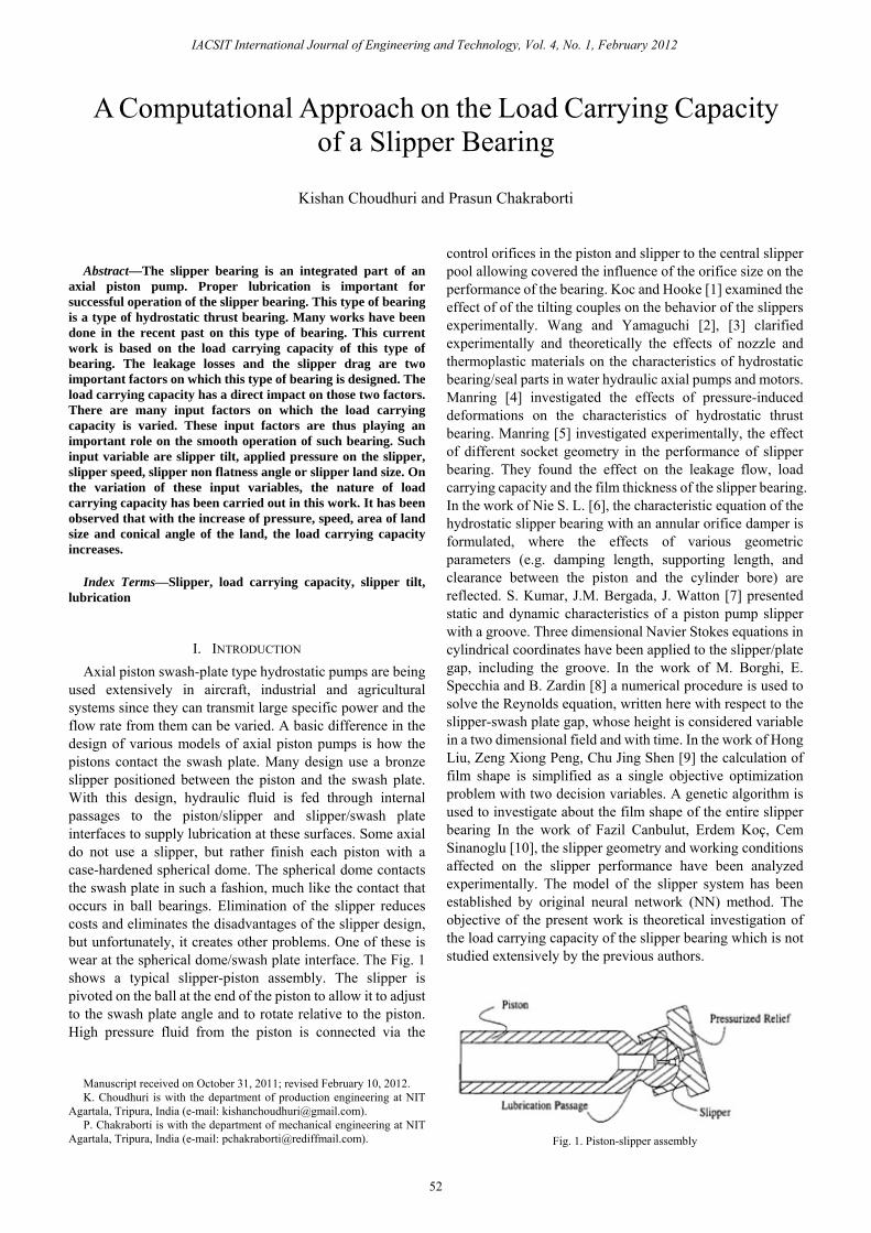
used extensively in aircraft, industrial and agricultural systems since they can transmit large specific power and the flow rate from them can be varied. A basic difference in the design of various models of axial piston pumps is how the pistons contact the swash plate. Many design use a bronze slipper positioned between the piston and the swash plate. With this design, hydraulic fluid is fed through internal passages to the piston/slipper and slipper/swash plate interfaces to supply lubrication at these surfaces. Some axial do not use a slipper, but rather finish each piston with a case-hardened spherical dome. The spherical dome contacts the swash plate in such a fashion, much like the contact that occurs in ball bearings. Elimination of the slipper reduces costs and eliminates the disadvantages of the slipper design, but unfortunately, it creates other problems. One of these is wear at the spherical dome/swash plate interface. The Fig. 1 shows a typical slipper-piston assembly. The slipper is pivoted on the ball at the end of the piston to allow it to adjust to the swash plate angle and to rotate relative to the piston. High pressure fluid from the piston is connected via the
Manuscript received on October 31, 2011; revised February 10, 2012. K. Choudhuri is with the department of production engineering at NIT
Agartala, Tripura, India (e-mail: [email protected]). P. Chakraborti is with the department of mechanical engineering at NIT
Agartala, Tripura, India (e-mail: [email protected]).
control orifices in the piston and slipper to the central slipper pool allowing covered the influence of the orifice size on the performance of the bearing. Koc and Hooke [1] examined the effect of of the tilting couples on the behavior of the slippers experimentally. Wang and Yamaguchi [2], [3] clarified experimentally and theoretically the effects of nozzle and thermoplastic materials on the characteristics of hydrostatic bearing/seal parts in water hydraulic axial pumps and motors. Manring [4] investigated the effects of pressure-induced deformations on the characteristics of hydrostatic thrust bearing. Manring [5] investigated experimentally, the effect of different socket geometry in the performance of slipper bearing. They found the effect on the leakage flow, load carrying capacity and the film thickness of the slipper bearing. In the work of Nie S. L. [6], the characteristic equation of the hydrostatic slipper bearing with an annular orifice damper is formulated, where the effects of various geometric parameters (e.g. damping length, supporting length, and clearance between the piston and the cylinder bore) are reflected. S. Kumar, J.M. Bergada, J. Watton [7] presented static and dynamic characteristics of a piston pump slipper with a groove. Three dimensional Navier Stokes equations in cylindrical coordinates have been applied to the slipper/plate gap, including the groove. In the work of M. Borghi, E. Specchia and B. Zardin [8] a numerical procedure is used to solve the Reynolds equation, written here with respect to the slipper-swash plate gap, whose height is considered variable in a two dimensional field and with time. In the work of Hong Liu, Zeng Xiong Peng, Chu Jing Shen [9] the calculation of film shape is simplified as a single objective optimization problem with two decision variables. A genetic algorithm is used to investigate about the film shape of the entire slipper bearing In the work of Fazil Canbulut, Erdem Koç, Cem Sinanoglu [10], the slipper geometry and working conditions affected on the slipper performance have been analyzed experimentally. The model of the slipper system has been established by original neural network (NN) method. The objective of the present work is theoretical investigation of the load carrying capacity of the slipper bearing which is not studied extensively by the previous authors.
Fig. 1. Piston-slipper assembly
A Computational Approach on the Load Carrying Capacity of a Slipper Bearing
Kishan Choudhuri and Prasun Chakraborti
IACSIT International Journal of Engineering and Technology, Vol. 4, No. 1, February 2012
52

II. MATHEMATICAL MODEL The following assumptions are taken into account to
derive all the equations: • Body forces acting on the lubricant such as gravitational,
magnetic or electrical are neglected
• The pressure induced flow in the circumferential direction
is neglected
• The pressure is assumed to constant through the thickness
of the lubricating fluid.
• The lubricant is Newtonian.
• Viscosity is considered to be constant through the
thickness of the lubricating film.
• The flow is laminar.
• Surface velocities are considered to be constant in
direction.
• The land is approximately conical.
Slipper is having a circular pocket, which is surrounded by a land as shown in Fig. 1. The orifice connects the slipper
pocket to the piston bore which feeds it with oil thus establishing a pressure in the slipper pocket which is approximately equal to piston pressure. Improper lubrication in the slipper land may cause damage of slipper land (vide Fig 2). The oil inside the slipper pocket lubricates the total slipper area. Referring to the Fig.3, the clearance between the land of an untilted slipper and the swash plate can be expressed as h=hd − d + az. When slipper is tilted (Fig.3) this clearance becomes ( )cosa dh h d az tr θ= − + +
And in non-dimensional form ( )1 cos dh d az tr θ= − + +
•
Fig. 2. Wear in the slipper land due to improper lubrication
List of Symbols
a Conical angle of the slipper. Q Non dimensional form of Q a Non-dimensional value of a r Radius of any point on the slipper land
d f li t*a Another non-dimensional form of a r Non-dimensional value of r
d A dimension for a conical slipper cr Mid-land radius
d Non-dimensional value of d cr Non dimensional mid land radius
e A measure of slipper tilt ir Inner radius of slipper
G Non dimensional hydrodynamic parameter. ir Non-dimensional value of ir
h A variable defining film thickness or Outer radius of slipper.
ah Average film thickness. or Non-dimensional value of or
h Non-dimensional value of h t Slipper tilt in radian
ch The non dimensional film thickness at the id di f th l d
t Non-dimensional value of t
oh Non dimensional film thickness at middle l d f tilt
*t Another non-dimensional form of t
O Orifice size coefficient u Slipper velocity
fO Orifice coefficient of the orifice between i t li d d li k t
W Load carrying capacity for the slipper p Variable defining pressure in the slipper land W Non-dimensional value of W
sp Pressure in slipper pocket w Non dimensional width of the slipper land
sp Non-dimensional value of sp θ Angle measured from trailing edge of the lip Non-dimensional value of p
dθ Angle measured from the position of i lQ Drain flow through the conical and tilted
li
mθ Angle of maximum clearance.
IACSIT International Journal of Engineering and Technology, Vol. 4, No. 1, February 2012
53

Fig. 3. The geometry of slipper bearing
Pressure distribution over a slipper land must satisfy Reynold’s equation, which is expressed in polar coordinate by:
⎥⎦⎤
⎢⎣⎡
∂∂−
∂∂
=∂∂
∂∂+
∂∂
∂∂
θθ
θ
θμθμ
sin1cos2
121
121 3
2
3
hrr
hu
phrr
prhrr
Making Non-dimensional form and introducing the non-dimensional group
2o
a p
urGh pμ=
( ) ( )⎪⎭
⎪⎬⎫
⎪⎩
⎪⎨⎧
⎥⎥⎦
⎤
⎢⎢⎣
⎡+−−++
+=
2cos3coscos
6
2
3
ztahC
rCtarzC
hrGAp
dcc
mc
cc
θθθ
where 1 cos dc ch d tr θ= − + is the non-dimensional film
thickness at the mid radius of the land. Constants A and C can be found out from the boundary conditions. The boundary conditions are
At ,i sr r p p= = and at , 0or r p= =
This leads to a pressure distribution:
( ) ( )( )( )( )4coscos3
4cos23
24
21
22
3
2222
wztah
G
wztahw
prwwz
wzpp
mc
dc
s
cs
−++
−++⎥⎥⎦
⎤
⎢⎢⎣
⎡ −+−=
θθ
θ
(1) where, o i
o
r rwr−= is the non-dimensional width of the slipper
land. The first group of the equation (1) corresponds the
hydrostatic pressure distribution for flat and untilted slipper and the second group corresponds the hydrostatic pressure
distribution produced by coning of the land and the tilt of the slipper. The final group represents the hydrodynamic effects due to conical shape of the land, slipper tilt and the slipper velocity.
The first group of the equation (1) can be replaced by an analytical solution of pressure for flat and untilt slipper which is derived in Appendix A. That analytical solution can be found out as
( )( )
lnln
os
i o
r rp p
r r=
Thus ultimately the equation of pressure distribution over the land of the slipper can be written as
( )( ) ( )
( ) .4
coscos3
4cos
23
lnln
22
3
22
⎟⎟
⎠
⎞
⎜⎜
⎝
⎛−+
+⎟⎟
⎠
⎞
⎜⎜
⎝
⎛−++=
wztah
G
wztahw
prrrrpp
mc
dc
s
oi
os
θθ
θ
Non-dimensional load is given as
( ) θπ
dzdzrpWw
wc∫ ∫
+
−+=
2
0
2
2 Putting the non-dimensional pressure the load carrying
capacity can be derived as
( )( )
( ) ( )[ ]aeeteh
wrG
eet
ea
hwrp
rrrrp
W
m
o
c
o
cs
io
ios
321
cos.
2
111
142
ln2
25.223
3
22
222
−+−
−
⎥⎥⎦
⎤
⎢⎢⎣
⎡⎟⎟⎠
⎞⎜⎜⎝
⎛
−−+
−−
−=
θπ
ππ
(2) where
ao
a
h dhh−= and
1ctred
=−
In equation (2) the first group is load carrying capacity for flat and untilted slipper. The second group is its modification for conical shape of the land and slipper tilt. The third group is the hydrodynamic effect on the load carrying capacity. Finding out the appropriate G value is the main issue to solve the slipper equations. This is done from load equilibrium conditions. This analysis is different from Hook’s analysis only by the equation of load equilibrium. The hydrodynamic parameter
2o
a p
urGh pμ=
Fig. 4. Variation of load carrying capacity with slipper tilt for different speeds.
IACSIT International Journal of Engineering and Technology, Vol. 4, No. 1, February 2012
54

which is dependent on ah and
( )21
ln26 ⎥⎦
⎤⎢⎣
⎡= io
soa rr
prh
ρμ
III. RESULTS As the solution is directly got from the analytical method,
the plotting can be done using MATLAB programming window. All the equations are set in the programming environment of the MATLAB software and the solutions are plotted. Generally the maximum clearance occurs very near to the leading edge. In the analysis of theoretical load carrying capacity, programming is developed with the fact that in the leading edge maximum clearance occurs. The load carrying capacity is plotted against the slipper tilt. The slipper is considered as perfectly flat. For Fig. 4, the pressure is kept constant at 120 bar and the plot is drawn for different speeds. For the Fig. 5, the slipper speed is kept constant at 1500 rpm and the plot is drawn for different pressure. It is clear from the figure the load carrying capacity of the slipper increases with the increase of the slipper tilt angle as well as the pressure, It can be seen from the graph that after some point of tilt angle the load carrying capacity goes out of the computation zone that is some term goes to form complex number and computation leaves the program loop.
Fig. 5. Variation of load carrying capacity with slipper tilt for different
pressures.
Fig. 6. Variation of load carrying capacity with slipper tilt for different non
flatness angles.
From the Fig 4 it is clear that the load carrying capacity of the slipper increases with the slipper speed. In this figure also it can be seen that after a specific tilt point the load carrying capacity becomes incomputable. An increase of slipper tilt or the slipper speed increases the slipper load carrying capacity clears that hydrodynamic lift is generated. Also for a hydrostatic slipper a very expected phenomena is that an increase of applied pressure increases the load carrying capacity. Therefore the result of load carrying capacity makes a clear fact that for a successful slipper operation, the slipper must move with a very small angle of tilt. Physically a consideration can be made that at higher tilt angle the fluid film does not exist. It is observed for a higher theoretical tilt the slipper does not work. Apparently the fluid film breaks after a maximum angle of tilt. This angle depends on the slipper dimension and applied piston pressure, but does not depend on the slipper speed. For a small angle of tilt the hydrodynamic lift is observed. If the non flatness angle increases, the load carrying capacity is decreased for small tilt angle and is increased for large tilt angle as shown in Fig. 6. If the land area increases then the load carrying capacity also increases and the fluid film break in a small tilt angle as shown in Fig 7.
Fig. 7. Variation of load carrying capacity with slipper tilt for different
slipper area.
IV. CONCLUSION It has been observed that the fluid film breaks after a
certain tilt angle. The load carrying capacity has a direct relation with the pressure, land area, conical angle of the land and the sleeper speed. As the slipper is tilted and there is a direct relation of load carrying capacity with the applied load, there must be a hydrodynamic lift of the slipper. Moreover, there is an extensive rise in the load carrying capacity if the pressure and speed of the slipper is increased. If there is a decrease in the land area there is a decrease in the load carrying capacity but the fluid film of lower land size, last long with a higher tilt. If the conical angle of the land is increased, for small tilt angle the load carrying capacity decreases but for higher tilt angle the load carrying capacity increases. It is also observed that the fluid film last long for smaller conical angle. It is obvious that there is a tilt when there is relative motion between slipper and swash plate.
IACSIT International Journal of Engineering and Technology, Vol. 4, No. 1, February 2012
55
For more practicality of this tilt angle more computation is required.
REFERENCES [1] E. Koc and C. J. Hooke, “Investigation into the effects of orifice size
offset and over clamp ratio on the lubrication of slipper bearings,” Tribology International, vol. 29, no.4, pp. 299-305, 1996.
[2] X. Wang and A. Yamaguchi, “Characteristics of hydrostatic bearing/seal parts for water hydraulic pumps and motors. Part 1: Experiment and theory,” Tribology International, vol. 35, pp. 425–433, 2002.
[3] X. Wang and A. Yamaguchi, “Characteristics of hydrostatic bearing/seal parts for water hydraulic pumps and motors. Part 2: On eccentric loading and power losses,” Tribology International, vol. 35, pp. 435–442, 2002.
[4] N. D. Manring, R. E. Johnson, and H. P. Cherukuri, “The impact of linear deformations on stationary hydrostatic thrust bearings,” American Society Mechanical Engineers, Journal of Tribology, vol. 124, pp. 874–877, 2002.
[5] N. D. Manring, “Experimental Studies on the Performance of Slipper Bearings within Axial-Piston Pumps,” American Society Mechanical Engineers, Journal of Tribology, vol. 126, pp. 511–518, 2004.
[6] S. L. Nie, “Tribological study on hydrostatic slipper bearing with annular orifice damper for water hydraulic axial piston motor,” Tribology International, vol. 39, pp. 1342–1354, 2006.
[7] S. Kumar, J.M. Bergada, and J. Watton “ Axial piston pump grooved slipper analysis by CFD simulation of three-dimensional NVS equation in cylindrical coordinates.” Computers & Fluids Vol. 38 pp-648–663, 2009
[8] M. Borghi, E. Specchia, and B. Zardin, “Numerical Analysis of the Dynamic Behaviour of Axial Piston Pumps and Motors Slipper Bearings,” SAE International Journal of Passenger Cars- Mechanical Systems, vol. 2, no. 1, pp-1285-1303, 2009.
[9] H. Liu, Z. Xiong, and C. J. Shen, “Film Shape Research of Slipper Bearing in Axial Piston Pump Based on Genetic Algorithms,” Advanced Materials Research, vol. 301 – 303, pp-1533-1538, 2011.
[10] F. Canbulut, E. Koç, and C. Sinanoglu, “Design of artificial neural networks for slipper analysis of axial piston pumps,” Industrial Lubrication and Tribology, vol. 61, no. 2, pp.67 – 77, 2009.
[11] E. Koc, “Slipper balance in axial piston pumps and motors,” American Society Mechanical Engineers, Journal of Tribology, vol. 114, pp. 766-772, 1992.
[12] C. J. Hooke and Y. P. Kakoullis, “The Effect of Non-Flatness on the Performance of Slippers in Axial Piston Pumps,” Proceedings of Institutions of Mechanical Engineers, vol. 197C, pp. 239-247, 1983. E. Koc and C. J. Hooke, “Consideration in the design of partially hydrostatic slipper bearings,” Tribology International, vol. 30, no. 11, pp. 815-823, 1997.
[13] C. J. Hooke and Y. Li K, “The Lubrication of Over clamped Slipper in Axial Piston Pumps,” Proceedings of Institutions of Mechanical Engineers, vol. 202, no. C4, pp. 117-123, 1988.
[14] C. J. Hooke and Y. Li K, “The lubrication of slippers in axial piston pumps and motors,” Proceedings of Institutions of Mechanical Engineers, vol. 203, pp. 343-350, 1989.
[15] N. Iboshi and A. Yamaguchi ,“ Characteristics of a slipper bearing for swash plate type axial piston pump and motor,” Bulletin of Japan Society Mechanical Engineers, vol. 26, no. 219, pp. 1583-1589 ,1983.
[16] E. Koc, “Slipper balance in axial piston pumps and motors,” American Society Mechanical Engineers, Journal of Tribology, vol. 114, pp. 766-772, 1992.
[17] F. Canbulut, “Design of an artificial neural network for analysis of frictional power loss of hydrostatic slipper bearings,” Journal of Tribology, vol. 17, no. 4, pp. 887 – 899, 2004.
[18] A. Crook and M. J. Fisher, “An investigation into the dynamic behavior of hydrostatic slipper bearing,” BHRA Report RR 1023, 1969.
[19] S. V. Cunningham and D. McGillivray, “The design and operation of hydrostatic slipper pad bearings in hydrostatic motors,” Proceedings of Institutions of Mechanical Engineers, vol. 180, no. 3L, 1966.
[20] M. J. Fisher, “A theoretical determination of some characteristics of tilted hydrostatic slipper pad,” BHRA Report RR728, 1962.
[21] R. M. Harris, “Slipper pads in swash-plate type axial piston pumps,” Journal of Dynamic Systems Measurements and Control, vol. 118, pp. 41-47, 1996.
[22] W. D. Milestone, “The Kinematic Analysis of Axial-Piston Pumps,” Mechanism and Machine Theory, vol. 18, no. 16, pp. 475-479, 1983.
[23] N. D. Manring, “The Torque on the Input Shaft of an Axial Piston Swash Plate Type Hydrostatic Pump,” Journal of Dynamic Systems Measurements and Control, vol. 120, no. 1, pp. 57-62. 1998.
[24] N. A. Shute, l D. E. Turnbul, “The minimum power loss of hydrostatic slipper bearing,” BHRA Report SP721, 1962(a).
[25] N. A. Shute, l D. E. Turnbul, “The losses of hydrostatic slipper bearing under various operating conditions,” BHRA Report SP743, 1962(b).
Mr. Kishan Choudhuri is working as an Assistant Professor in NIT, Agartala from 2008. He got his Bachelor in Enginineering in 1998 from Tripura Engineering college. He got Master in Technology from Regional Engineering College, Durgapur in 2000. His area of interest is in fluid power and control.
Dr. Prasun Chakraborti is working as Associate Professor in NIT Agartala from 1984. He got his Bachelor in Enginineering in 1983 from Tripura Engineering college. He got Master in Technology from Indian Institute of Technology, Delhi in 1992 and got PhD degree from Indian Institute of Technology, Kharagpur in 2006. His area of interest is in friction wear and lubrication.
IACSIT International Journal of Engineering and Technology, Vol. 4, No. 1, February 2012
56


![[XLS] · Web view317 317 317 317 315 94 315 94 86 86 86 426 426 426 316 239 316 239 317 317 317 315 94 315 94 315 315 315 315 426 274 136 274 136 274 136 274 136 274 188 274 188 274](https://img.dokumen.tips/doc/110x75/5abaa3447f8b9a567c8bbc31/xls-view317-317-317-317-315-94-315-94-86-86-86-426-426-426-316-239-316-239-317.jpg)

![[XLS] · Web view317 317 317 317 316 239 316 239 315 94 315 94 86 86 86 398 426 426 426 316 239 316 239 317 317 317 315 94 315 94 315 315 315 315 426 316 239 274 136 274 136 274 136](https://img.dokumen.tips/doc/110x75/5abaa3447f8b9a567c8bbc29/xls-view317-317-317-317-316-239-316-239-315-94-315-94-86-86-86-398-426-426-426.jpg)