Embed Size (px)
Citation preview

Journal of Mechanical Engineering and Sciences
ISSN (Print): 2289-4659; e-ISSN: 2231-8380
Volume 13, Issue 2, pp. 4756-4776, June 2019
© Universiti Malaysia Pahang, Malaysia
DOI: https://doi.org/10.15282/jmes.13.2.2019.01.0398
4756
A comprehensive study on the buckling behaviour of woven composite plates with
major aerospace cutouts under uniaxial loading
S. B. Rayhan
Institute of Flight Vehicle Engineering, Nanchang Hangkong University
696 South Fenghe Avenue, Nanchang, China, *Email: [email protected]
Phone: +86-13080933760
ABSTRACT
Current research paper presents a comprehensive linear buckling study based on Finite
Element Method (FEM) to investigate the effect of cutout shape and area on the buckling
behaviour of E-glass woven composite plates under uniaxial loading. Considered plate has a
dimension of 150mm × 75mm × 3mm where loading edges are simple supported (shorter
side) and other two edges are free. Major aerospace cutout shapes i.e. circular, square,
elliptical (horizontal and vertical) and diamond are studied to understand their effect on
plates’ critical buckling load. FE code Ansys is adopted to investigate the case studies. A
limited number of experimental buckling tests are also carried out and compared with the FE
code results. From finite element analyses, it is found that for any cutout shape, as the cutout
area increases, buckling load decreases significantly. Moreover, increasing the plate
thickness by 0.5mm can raise the buckling load up to 50%. More importantly, fibre
orientation angle has most significant effect on the critical buckling load of plates where fibre
orientation aligned with loading direction can increase the plates’ critical buckling load from
2.6 to 2.8 times than aligned with 900. Finally, among all cutout shapes, elliptical (vertical)
cutout shows better buckling results.
Keywords: Finite element method; E-glass composite plate; cutout; critical buckling.
INTRODUCTION
Composite materials are extensively used in aerospace, automobile and ship building
industries for their superior mechanical properties like high stiffness, strength to weight
ratios, longer fatigue life and better resistance to corrosion etc. In these thin-walled structures,
cutouts are often introduced for various purposes like weight reduction, access for electrical
wires, hydraulic and fuel lines, damage inspection and maintenance. However, presence of
these openings can drastically reduce the stability of the structure both locally and globally.
Shanmugam et al. [1] proposed a simplified formula to predict the critical buckling load in
terms of opening area ratio and plate slenderness for isotropic plates. The results were found
to be slightly conservative with an error of less than 10%. A semi-analytical solution method
is presented for the buckling analysis of orthotropic laminated plates with reinforced cutouts
subjected to uniform and non-uniform compression loading. It was found that the buckling

S. B. Rayhan et. al / Journal of Mechanical Engineering and Sciences 13(2) 2019 4756-4776
4757
strength of the panel increases with the increasing thickness and radius of the cutout
reinforcement [2]. Ovesy and Fazilati [3] introduced two different modeling techniques and
applied to S-a (Semi analytical) as well as spline FSM (Finite Strip Method) formulations in
order to investigate the buckling strength and free vibration behavior of isotropic and layered
composite plates containing square and circular cutouts. They concluded that the longitudinal
strip assemble approach in modeling cutouts, whilst being more accurate, is only applicable
to rectangular cutout shape and can only be implemented by the spline FSM formulation.
However, at the expense of some accuracy, the negative stiffness approach has the
advantages of having fewer degrees of freedom, having the ability to deal with different
cutout shapes as well as being suitable for both spline and S-a FSM formulations. Recently,
Gong [4] presented theoretical solutions based on improved energy method to predict the
helical buckling behavior of pipes in vertical, inclined and horizontal wells. He showed that
the new formula can solve the Pipe-in-Pipe's (PIP) critical helical buckling forces
successfully and provides a deeper insight on the PIP's helical buckling onset, as well as the
post helical buckling behavior. More recently, an extended Ritz formulation for the analysis
of buckling and post buckling behavior of cracked composite multi layered plate is presented
where the formulation agrees quite well with the finite element simulations which confirms
the accuracy and potential of the formulation [5].
Jain and Kumar [6] used finite element method to study the buckling and post
buckling response of symmetric square laminates with a central circular/elliptical cutout
under uniaxial compression. They concluded that ellipse aligned along the loading direction
has lower buckling load than that with a corresponding circular cutout. However, a stochastic
finite element method is used by Onkar et al. [7] to predict the critical buckling load of
composite laminate under uniaxial and shear loading found that plates with horizontal and
vertical elliptical cutouts generally show an increase in critical buckling load compared with
plates with a circular cutout. Ghannadpour et al. [8] studied rectangular composite plates with
circular/elliptical cutouts and Kumar and Singh [9] studied square composite plates with
circular/elliptical cutouts. Both of the studies revealed that in some cases, plates with
circular/elliptical cutouts may have higher buckling load than the corresponding plates
without a cutout. More recently, a non-uniform edge loading on buckling characteristics of
laminated composite panels with and without cutout were investigated by Rajanna et al. [10].
It was found that in most cases, the panel with larger cutout offers higher buckling resistance
compared to the panel without cutouts.
Murat et al. [11] and Baba [12] investigated composite plates with U-shaped cutouts
and circular and semi-circular cutouts. They found that fiber orientation angle has strong
influence on plate buckling load. Moreover, numerical and experimental studies, carried out
by Aktas and Balcioglu [13] on pultruded composite beams with circular cutouts revealed
that buckling load can be enhanced 11 times by changing rowing orientation angle. Tercan
and Aktas [14] analyzed rib knitting glass/epoxy laminated plates with cutouts where they
focused on the tightness level of knitted fabrics. They found that for all cutout shapes,
buckling load decreases by higher tightness level of rib knitting in glass/epoxy plates.
In order to reduce the cutout stress concentration and increase the buckling stability
of composite panels, Guo et al. [15] conducted experimental and numerical analyses for shear
loaded laminated and sandwich composite panels. They came to the conclusion that the most
effective means of improving the buckling stability of composite panels without weight
penalty is to employ sandwich design, and the most effective reinforcement for reducing

A comprehensive study on the buckling behaviour of woven composite plates with major aerospace cutouts
under uniaxial loading
4758
sandwich panel stress concentration at minimum weight cost is the central tube design. Lopes
et al. [16] used AFP technology to fabricate variable stiffness panels. Their research showed
that it is possible to design and manufacture composite panels whose buckling and first-ply
failure responses are insensitive to the existence of a central hole. Guo et al. [17] studied
composite C-section structure having circular and diamond shape cutout with flange
reinforcements. They revealed that both cutout and reinforcement has little effect on the
buckling stability of C-section structure. A comprehensive study carried out by Kim et al.
[18] on different stiffening method on perforated plates concluded that for different loading
conditions e.g. longitudinal compression, transverse compression and in plane edge shear
loading doubling plate method, carling stiffener method and face plating method works better
respectively.
Singh and Kumar [19] carried out FE analyses to various cutout shapes and sizes on
buckling and postbuckling response of square quasi-isotropic composite laminate under
uniaxial compression loading where they found that cutout reduces the buckling load of the
laminate and it reduces further with increase in cutout size. Singh et al. [20] investigated thin
rectangular isotropic plates with central circular cutouts subjected to partial edge
compression using FEM. They found that for plates with cutouts have reduced critical
buckling load compared to plates without cutouts, however, influence of various partial edge
compression are almost same. Rajanna et al. [21] studied the influence of centrally placed
circular and square cutouts on vibration and buckling characteristics of different ply oriented
laminated panels under the action of uniaxial compression, uniaxial tension and biaxial,
compression-tension loading configurations. It was found that even though the tensile
buckling loads are higher than that of compressive buckling loads, it continuously reduces
with the increased cutout sizes irrespective of ply orientations.
Komur and Sonmez [22] studied the elastic buckling behavior of plates with circular
cutouts where the cutout location varied along the principal X-axis of plates subjected to
linearly varying loading. The results show that center of a circular hole should not be placed
at the end of the outer panel for all loading cases. A grooved shaped cutout panels are
investigated for steel plates by Mohtaram et al. [23] found that with identical values of the
groove angle , the buckling load decreases with increasing the length of the groove, and
this effect is most prominent when = 900. A numerical investigation was carried out by
Narayana et al. [24] to study the effect of plate aspect ratio and location of the
square/rectangular cutout on the buckling behavior of a sixteen ply quasi-isotropic
graphite/epoxy symmetrically laminated rectangular composite plate subjected to various in-
plane compressive loading. Their studies revealed that cutout orientation has effect on
buckling when it is located at the center. However, towards the edge, the cutout orientation
has insignificant effect where no effect is observed when the cutouts move in Y-direction.
Erkliğ and Yeter [25] studied various cutout shape effects on the buckling characteristics of
composite plates and found that cutout orientation angle has less effect on the critical
buckling load. Erkliğ et al. [26] investigated lateral buckling behavior of polymer matrix
composites with circular, rectangular, square, elliptical and triangle cutouts and found that
elliptical cutout is the best and square cutout is the worst. Recently, research on buckling
analyses were conducted by Shariati et al. [27] on steel plates having circular cutouts. Their
studies revealed that buckling load is lower than the yield load, and elastic buckling occurred
in all specimens. An experimental [28] and numerical [29] research was carried out on multi-
directional CFRP laminates subjected to quasi static shear loading with cutouts of three

S. B. Rayhan et. al / Journal of Mechanical Engineering and Sciences 13(2) 2019 4756-4776
4759
different forms, including circular, curved-diamond and rounded-rectangular shape. It was
demonstrated that the presence of cutouts does result in a significant reduction in structural
stability and structural buckling occurs far before the material failure.
From the above literature review, it was found that even though theoretical
formulations of solving critical buckling loads of structures are successful [4,5] but plates
with cutouts have got limitations [1-3]. Based on Finite Element formulations and
experimental studies, plates with different cutout shapes [6-13, 19-29] and reinforcements
[15-18] were studied but comprehensive studies based on all major cutouts are notably
limited. This paper addresses the effect of all major cutout shapes (circular, square, horizontal
ellipse, vertical ellipse and diamond) and sizes, plate aspect ratio, ply thickness and fiber
orientation angle on the buckling behavior of E-glass composite plate.
MATERIALS AND METHODS
Specimen Preparation
Araldite LY556 and Hardener HY951 manufactured by Ciba Inc. was used as the matrix
composition and E-glass fiber TEX 2400 as the reinforcing agent to prepare the woven
composite laminate. A hand layup technique was adopted. In total, twelve fiber layers were
glued one above another applying resin on top of each layer to form the laminate. Nominal
thickness of the laminate was 3 mm with an approximate 44% fiber volume fraction.
In order to determine the mechanical properties of E-glass composite, tensile testing
samples were prepared according to ASTM standard [30]. For critical buckling load,
specimens were prepared with a dimension of 150mm (length) and 75mm (width). For
perforated specimens, both circular and square holes were created at the center. Seven
different kind of plates, without hole, with a circular hole of diameter 10mm, 30mm and
50mm and with square hole of 10mm, 30mm and 50mm side by side were prepared. In total,
thirty-five specimens were prepared where each five similar specimens were experimented
to confirm the average critical buckling load of the particular composite plate. All the
specimen were prepared and tested in School of Material Science and Engineering, Nanchang
Hangkong University.
Experimental Setup and Material Testing
For both tensile tests and buckling analyses, a servo Hydraulic Universal Testing Machine
(MTS-CN 100) with a maximum capacity of 200KN was used. The mechanical properties of
the E-glass composite material are given below in Table 1.
Table 1. Mechanical properties of E-glass composite material.
xxE
(GPa) yy zzE E
(GPa)
xy zx yz xy zxG G
(GPa) yzG
(GPa)
49.148 16.870 0.334 0.114 2.87 1.5
A comprehensive study on the buckling behaviour of woven composite plates with major aerospace cutouts
under uniaxial loading
4760
For buckling case studies, composite plates were simply supported on shorter edges and
longer two edges were free. Plates were loaded slowly at 1 mm/min rate and “lateral
deflection vs load” graph was plotted by the digital computer connected with the hydraulic
actuator for each case. In order to determine the critical buckling load from the graph, point
of inflection was used [31].
Finite Element Analysis Setup
For numerical solutions, FE code Ansys was adopted to find the critical buckling load of the
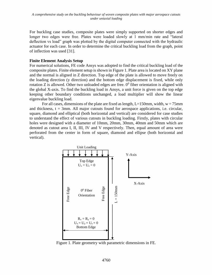
composite plates. Finite element setup is shown in Figure 1. Plate area is located on XY plane
and the normal is aligned in Z direction. Top edge of the plate is allowed to move freely on
the loading direction (y direction) and the bottom edge displacement is fixed, while only
rotation Z is allowed. Other two unloaded edges are free. 00 fiber orientation is aligned with
the global X-axis. To find the buckling load in Ansys, a unit force is given on the top edge
keeping other boundary conditions unchanged, a load multiplier will show the linear
eigenvalue buckling load.
For all cases, dimensions of the plate are fixed as length, L=150mm, width, w = 75mm
and thickness, t = 3mm. All major cutouts found for aerospace applications, i.e. circular,
square, diamond and elliptical (both horizontal and vertical) are considered for case studies
to understand the effect of various cutouts in buckling loading. Firstly, plates with circular
holes were designed with a diameter of 10mm, 20mm, 30mm, 40mm and 50mm which are
denoted as cutout area I, II, III, IV and V respectively. Then, equal amount of area were
perforated from the center in form of square, diamond and ellipse (both horizontal and
vertical).
Figure 1. Plate geometry with parametric dimensions in FE.
Unit Loading
Y-Axis
X-Axis
Top Edge
Ux = Uz = 0
Rx = Ry = 0
Ux = Uy = Uz = 0
Bottom Edge
Fre
e E
dge
Fre
e E
dge
00 Fiber
Orientation
L =
150m
m
S. B. Rayhan et. al / Journal of Mechanical Engineering and Sciences 13(2) 2019 4756-4776
4761
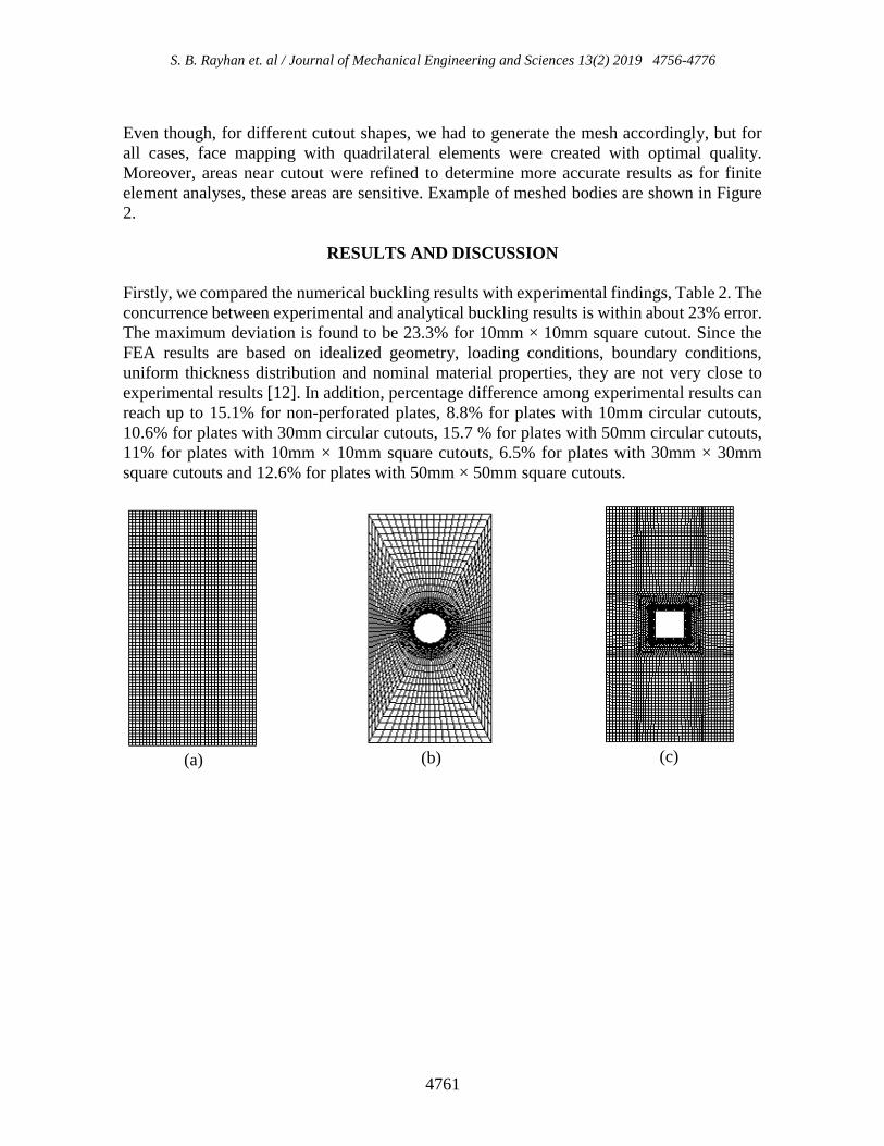
Even though, for different cutout shapes, we had to generate the mesh accordingly, but for
all cases, face mapping with quadrilateral elements were created with optimal quality.
Moreover, areas near cutout were refined to determine more accurate results as for finite
element analyses, these areas are sensitive. Example of meshed bodies are shown in Figure
2.
RESULTS AND DISCUSSION
Firstly, we compared the numerical buckling results with experimental findings, Table 2. The
concurrence between experimental and analytical buckling results is within about 23% error.
The maximum deviation is found to be 23.3% for 10mm × 10mm square cutout. Since the
FEA results are based on idealized geometry, loading conditions, boundary conditions,
uniform thickness distribution and nominal material properties, they are not very close to
experimental results [12]. In addition, percentage difference among experimental results can
reach up to 15.1% for non-perforated plates, 8.8% for plates with 10mm circular cutouts,
10.6% for plates with 30mm circular cutouts, 15.7 % for plates with 50mm circular cutouts,
11% for plates with 10mm × 10mm square cutouts, 6.5% for plates with 30mm × 30mm
square cutouts and 12.6% for plates with 50mm × 50mm square cutouts.
(a) (b) (c)

A comprehensive study on the buckling behaviour of woven composite plates with major aerospace cutouts
under uniaxial loading
4762
Figure 2. Meshed bodies of non-perforated and various perforated plates: (a) Non-
perforated plate, (b) plate with circular cutout, (c) plate with rectangular cutout, (d) plate
with elliptical cutout (horizontal), (e) plate with elliptical cutout (vertical) and (f) plate with
diamond cutout.
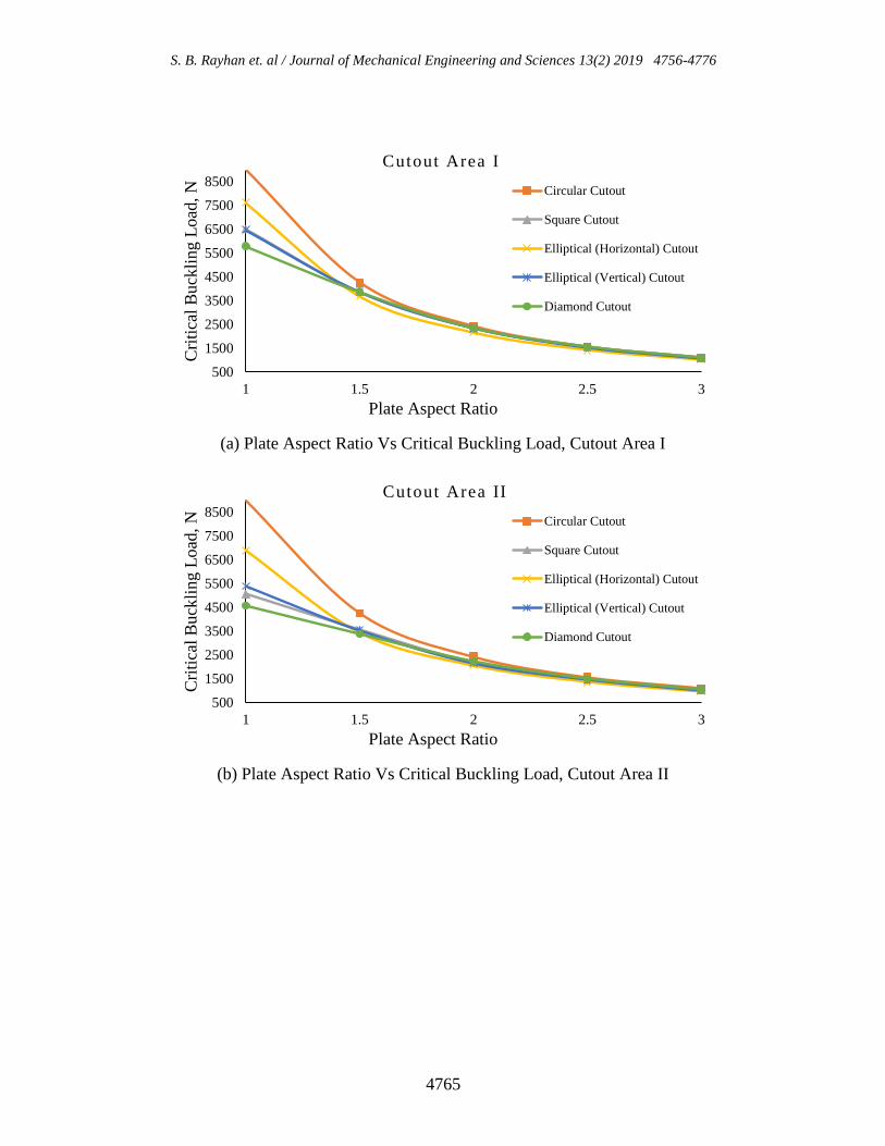
Effect of the Plate Aspect Ratio
Effect of the plate aspect ratio on the critical buckling load of plates is illustrated in Figure
3. In general, buckling load of the plate decreases with the increase of the plate aspect ratio.
(e) (f) (d)

S. B. Rayhan et. al / Journal of Mechanical Engineering and Sciences 13(2) 2019 4756-4776
4763
Table 2. Experimental and numerical buckling results.
Plate Type Specimen
No.
Experimental
Critical
Buckling
Load [N]
Average
Critical
Buckling
Load [N],
Experimental
FEA
Critical
Buckling
Load [N]
Deviation
% ,
between
Avg.
Critical
and FEA
Non-
perforated
Plate
I 2712
2952 2431.6 17.6
II 3156
III 2908
IV 3077
V 2908
Circular
Cutout,
10 mm
Diameter
I 2178
2227 2334.9 4.4
II 2325
III 2325
IV 2129
V 2178
Circular
Cutout,
30 mm
Diameter
I 2374
2296 2008 12.5
II 2423
III 2179
IV 2325
V 2178
Circular
Cutout,
50 mm
Diameter
I 1344
1226 1500.9 22.3
II 1148
III 1197
IV 1197
V 1246
Square
Cutout,
10 mm × 10
mm
I 1829
1770 2182.5 23.3
II 1682
III 1879
IV 1731
V 1731
Square
Cutout,
30 mm × 30
mm
I 1587
1535 1880.3 22.5
II 1486
III 1535
IV 1584
V 1487
Square
Cutout,
50 mm × 50
mm
I 1241
1153 1396.6 21.7
II 1094
III 1143
IV 1094
V 1192

A comprehensive study on the buckling behaviour of woven composite plates with major aerospace cutouts
under uniaxial loading
4764
In addition, it is found that for all cutout areas, cutout shape has strong influence on critical
buckling load when the plate aspect ratio is 1. For instance, for cutout area III, square cutout
has 8% higher buckling load than diamond cutout and around 61% higher buckling load than
circular and elliptical (vertical) cutouts. But this influence starts to decrease as the plate
aspect ratio increases.
Effect of the Plate Thickness
Figure 4 shows the effect of plate thickness i.e. ply number on the critical buckling load of
plates. It can be seen that the buckling load of the plate increases with the thickness of the
plate. More importantly, an increase of 0.5mm thickness can provide 50% higher buckling
load which becomes almost 120% for an increase of 1mm and this trend is identical for all
cutout areas and shapes. In addition, for all cutout areas, elliptical (vertical) cutout shows
highest buckling load while diamond cutouts are being the lowest.
Effect of the Fiber Orientation Angle
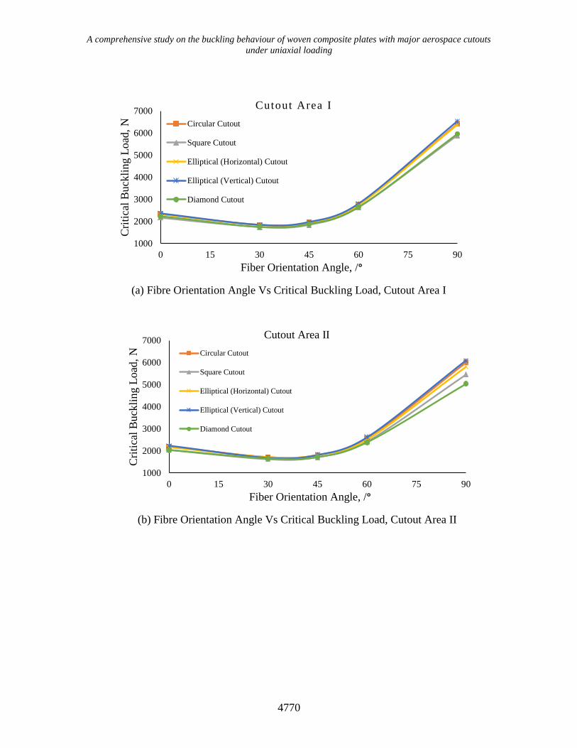
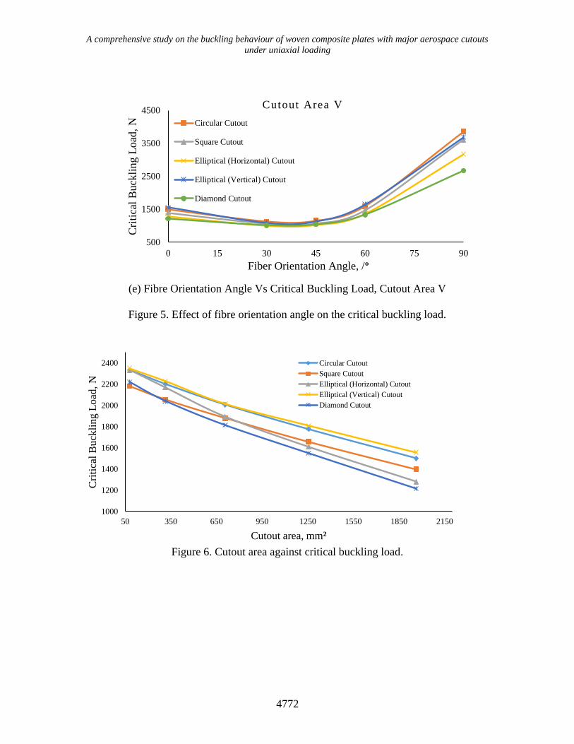
The effect of fiber orientation angle has been illustrated for all cutout areas in Figure 5. For
our case studies, 00 fiber orientation is perpendicular to the loading direction. As the fiber
orientation changes from 00 to 300, a decrease of buckling load is observed, around 21% -
22%, which is the lowest among all the fiber direction considered for our case studies. From
600 orientation, buckling load starts to increase and 900 fiber orientation (aligned with the
loading direction) shows almost 2.6 - 2.8 times higher buckling load than 00 fiber orientation.
In addition, for cutout area I and II, for all fiber orientation angles, elliptical (vertical) cutout
shows highest buckling load but this trend changes for other cutout areas. For cutout area III,
IV and V, only for 00 fiber orientation case, elliptical (vertical) cutout shows highest buckling
load, but for all other orientations, circular cutout performs better.
Effect of the Cutout Area and Shape
Effect of cutout area and shape on plates’ critical buckling load is shown in Figure 6 and
Figure 7. From Figure 6, it is apparent that for any cutout shape, the buckling load decreases
with the increase of the cutout area. Moreover, it is found that among all major cutouts,
elliptical (vertical) cutout shows maximum critical buckling load. However, both circular and
elliptical (vertical) cutouts have identical buckling load values where the difference never
exceeds more than 3.8%. But, for diamond cutout areas, this difference is highest, starts from
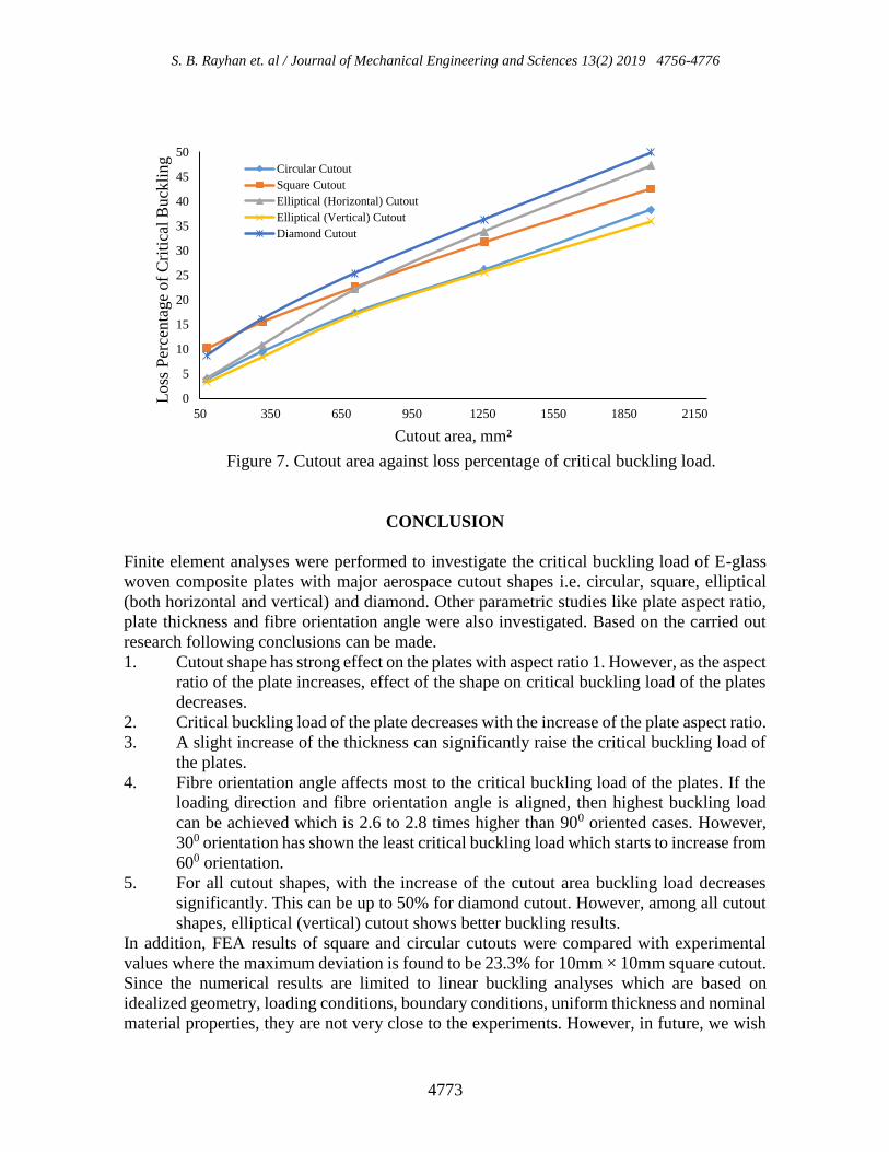
5.9% which reaches up to 29.1%. Figure 7 shows the loss percentage of critical buckling load
for all major cutouts. It is observed that among all major cutout shapes, elliptical (vertical)
cutout losses from 3.31% to 35.94% buckling stability as the cutout area increases which is
the least, where diamond cutout losses from 8.7 to 50% which is the highest among all the
analyzed shapes.
S. B. Rayhan et. al / Journal of Mechanical Engineering and Sciences 13(2) 2019 4756-4776
4765
(a) Plate Aspect Ratio Vs Critical Buckling Load, Cutout Area I
(b) Plate Aspect Ratio Vs Critical Buckling Load, Cutout Area II
500
1500
2500
3500
4500
5500
6500
7500
8500
1 1.5 2 2.5 3
Cri
tica
l B
uck
ling L
oad
, N
Plate Aspect Ratio
Cutout Area I
Circular Cutout
Square Cutout
Elliptical (Horizontal) Cutout
Elliptical (Vertical) Cutout
Diamond Cutout
500
1500
2500
3500
4500
5500
6500
7500
8500
1 1.5 2 2.5 3
Cri
tica
l B
uck
ling L
oad
, N
Plate Aspect Ratio
Cutout Area II
Circular Cutout
Square Cutout
Elliptical (Horizontal) Cutout
Elliptical (Vertical) Cutout
Diamond Cutout

A comprehensive study on the buckling behaviour of woven composite plates with major aerospace cutouts
under uniaxial loading
4766
(c) Plate Aspect Ratio Vs Critical Buckling Load, Cutout Area III
(d) Plate Aspect Ratio Vs Critical Buckling Load, Cutout Area IV
500
1500
2500
3500
4500
5500
6500
1 1.5 2 2.5 3
Cri
tica
l B
uck
ling L
oad
, N
Plate Aspect Ratio
Cutout Area III
Circular Cutout
Square Cutout
Elliptical (Horizontal) Cutout
Elliptical (Vertical) Cutout
Diamond Cutout
500
1500
2500
3500
4500
5500
1 1.5 2 2.5 3
Cri
tica
l B
uck
ling L
oad
, N
Plate Aspect Ratio
Cutout Area IV
Circular Cutout
Square Cutout
Elliptical (Horizontal) Cutout
Elliptical (Vertical) Cutout
Diamond Cutout

S. B. Rayhan et. al / Journal of Mechanical Engineering and Sciences 13(2) 2019 4756-4776
4767
(e) Plate Aspect Ratio Vs Critical Buckling Load, Cutout Area V
Figure 3. Effect of the plate aspect ratio on critical buckling load
(a) Plate Thickness Vs Critical Buckling Load, Cutout Area I
500
1500
2500
3500
4500
1 1.5 2 2.5 3
Cri
tica
l B
uck
ling L
oad
, N
Plate Aspect Ratio
Cutout Area V
Circular Cutout
Square Cutout
Elliptical (Horizontal) Cutout
Elliptical (Vertical) Cutout
Diamond Cutout
2000
3000
4000
5000
6000
7000
8000
9000
10000
3 3.5 4 4.5 5
Cri
tica
l B
uck
ling L
oad
, N
Plate Thickness, mm
Cutout Area I
Circular Cutout
Square Cutout
Elliptical (Horizontal) Cutout
Elliptical (Vertical) Cutout
Diamond Cutout

A comprehensive study on the buckling behaviour of woven composite plates with major aerospace cutouts
under uniaxial loading
4768
(b) Plate Thickness Vs Critical Buckling Load, Cutout Area II
(c) Plate Thickness Vs Critical Buckling Load, Cutout Area III
1500
2500
3500
4500
5500
6500
7500
8500
9500
3 3.5 4 4.5 5
Cri
tica
l B
uck
ling L
oad
, N
Plate Thickness, mm
Cutout Area II
Circular Cutout
Square Cutout
Elliptical (Horizontal) Cutout
Elliptical (Vertical) Cutout
Diamond Cutout
1500
2500
3500
4500
5500
6500
7500
8500
3 3.5 4 4.5 5
Cri
tica
l B
uck
ling L
oad
, N
Plate Thickness, mm
Cutout Area III
Circular Cutout
Square Cutout
Elliptical (Horizontal) Cutout
Elliptical (Vertical) Cutout
Diamond Cutout

S. B. Rayhan et. al / Journal of Mechanical Engineering and Sciences 13(2) 2019 4756-4776
4769
(d) Plate Thickness Vs Critical Buckling Load, Cutout Area IV
(e) Plate Thickness Vs Critical Buckling Load, Cutout Area V
Figure 4. Effect of the plate thickness on the critical buckling load.
1500
2500
3500
4500
5500
6500
7500
3 3.5 4 4.5 5
Cri
tica
l B
uck
ling L
oad
, N
Plate Thickness, mm
Cutout Area IV
Circular Cutout
Square Cutout
Elliptical (Horizontal) Cutout
Elliptical (Vertical) Cutout
Diamond Cutout
1000
2000
3000
4000
5000
6000
7000
3 3.5 4 4.5 5
Cri
tica
l B
uck
ling L
oad
, N
Plate Thickness, mm
Cutout Area V
Circular Cutout
Square Cutout
Elliptical (Horizontal) Cutout
Elliptical (Vertical) Cutout
Diamond Cutout
A comprehensive study on the buckling behaviour of woven composite plates with major aerospace cutouts
under uniaxial loading
4770
(a) Fibre Orientation Angle Vs Critical Buckling Load, Cutout Area I
(b) Fibre Orientation Angle Vs Critical Buckling Load, Cutout Area II
1000
2000
3000
4000
5000
6000
7000
0 15 30 45 60 75 90
Cri
tica
l B
uck
ling L
oad
, N
Fiber Orientation Angle, /°
Cutout Area I
Circular Cutout
Square Cutout
Elliptical (Horizontal) Cutout
Elliptical (Vertical) Cutout
Diamond Cutout
1000
2000
3000
4000
5000
6000
7000
0 15 30 45 60 75 90
Cri
tica
l B
uck
ling L
oad
, N
Fiber Orientation Angle, /°
Cutout Area II
Circular Cutout
Square Cutout
Elliptical (Horizontal) Cutout
Elliptical (Vertical) Cutout
Diamond Cutout

S. B. Rayhan et. al / Journal of Mechanical Engineering and Sciences 13(2) 2019 4756-4776
4771
(c) Fibre Orientation Angle Vs Critical Buckling Load, Cutout Area III
(d) Fibre Orientation Angle Vs Critical Buckling Load, Cutout Area IV
1000
2000
3000
4000
5000
6000
0 15 30 45 60 75 90
Cri
tica
l B
uck
ling L
oad
, N
Fiber Orientation Angle, /°
Cutout Area III
Circular Cutout
Square Cutout
Elliptical (Horizontal) Cutout
Elliptical (Vertical) Cutout
Diamond Cutout
1000
2000
3000
4000
5000
0 15 30 45 60 75 90
Cri
tica
l B
uck
ling L
oad
, N
Fiber Orientation Angle, /°
Cutout Area IV
Circular Cutout
Square Cutout
Elliptical (Horizontal) Cutout
Elliptical (Vertical) Cutout
Diamond Cutout
A comprehensive study on the buckling behaviour of woven composite plates with major aerospace cutouts
under uniaxial loading
4772
(e) Fibre Orientation Angle Vs Critical Buckling Load, Cutout Area V
Figure 5. Effect of fibre orientation angle on the critical buckling load.
Figure 6. Cutout area against critical buckling load.
500
1500
2500
3500
4500
0 15 30 45 60 75 90
Cri
tica
l B
uck
ling L
oad
, N
Fiber Orientation Angle, /°
Cutout Area V
Circular Cutout
Square Cutout
Elliptical (Horizontal) Cutout
Elliptical (Vertical) Cutout
Diamond Cutout
1000
1200
1400
1600
1800
2000
2200
2400
50 350 650 950 1250 1550 1850 2150
Cri
tica
l B
uck
lin
g L
oad
, N
Cutout area, mm²
Circular Cutout
Square Cutout
Elliptical (Horizontal) Cutout
Elliptical (Vertical) Cutout
Diamond Cutout
S. B. Rayhan et. al / Journal of Mechanical Engineering and Sciences 13(2) 2019 4756-4776
4773
Figure 7. Cutout area against loss percentage of critical buckling load.
CONCLUSION
Finite element analyses were performed to investigate the critical buckling load of E-glass
woven composite plates with major aerospace cutout shapes i.e. circular, square, elliptical
(both horizontal and vertical) and diamond. Other parametric studies like plate aspect ratio,
plate thickness and fibre orientation angle were also investigated. Based on the carried out
research following conclusions can be made.
1. Cutout shape has strong effect on the plates with aspect ratio 1. However, as the aspect
ratio of the plate increases, effect of the shape on critical buckling load of the plates
decreases.
2. Critical buckling load of the plate decreases with the increase of the plate aspect ratio.
3. A slight increase of the thickness can significantly raise the critical buckling load of
the plates.
4. Fibre orientation angle affects most to the critical buckling load of the plates. If the
loading direction and fibre orientation angle is aligned, then highest buckling load
can be achieved which is 2.6 to 2.8 times higher than 900 oriented cases. However,
300 orientation has shown the least critical buckling load which starts to increase from
600 orientation.
5. For all cutout shapes, with the increase of the cutout area buckling load decreases
significantly. This can be up to 50% for diamond cutout. However, among all cutout
shapes, elliptical (vertical) cutout shows better buckling results.
In addition, FEA results of square and circular cutouts were compared with experimental
values where the maximum deviation is found to be 23.3% for 10mm × 10mm square cutout.
Since the numerical results are limited to linear buckling analyses which are based on
idealized geometry, loading conditions, boundary conditions, uniform thickness and nominal
material properties, they are not very close to the experiments. However, in future, we wish
0
5
10
15
20
25
30
35
40
45
50
50 350 650 950 1250 1550 1850 2150
Lo
ss P
erce
nta
ge
of
Cri
tica
l B
uck
lin
g
Cutout area, mm²
Circular Cutout
Square Cutout
Elliptical (Horizontal) Cutout
Elliptical (Vertical) Cutout
Diamond Cutout

A comprehensive study on the buckling behaviour of woven composite plates with major aerospace cutouts
under uniaxial loading
4774
to continue our research on non-linear buckling analyses of composite plates based on
geometrical imperfection which may answer the large discrepancy between FEA and
experimental results.
ACKNOWLEDGEMENTS
The author would like to thank Professor Yu Chunjin of Institute of Flight Vehicle
Engineering, Nanchang Hangkong University to provide experimental data in collaboration
with School of Materials Science and Engineering, Nanchang Hangkong University.
REFERENCES
[1] Shanmugam N, Thevendran V, Tan Y. Design formula for axially compressed
perforated plates. Thin-Walled Structures. 1999;34(1):1-20.
[2] Oterkus E, Barut A, Madenci E. Buckling of Composite Plates with a Reinforced
Circular Cutout Subjected to Uniform and Non-Uniform Compression. 45th
AIAA/ASME/ASCE/AHS/ASC Structures, Structural Dynamics & Materials
Conference. 2004.
[3] Ovesy H, Fazilati J. Buckling and free vibration finite strip analysis of composite
plates with cutout based on two different modeling approaches. Composite
Structures. 2012;94(3):1250-1258.
[4] Gong L. Onset and Post Buckling of Pipe-in-Pipe’s Helical Buckling Using Improved
Energy Method. Proceedings of the 37th International Conference on Ocean,
Offshore and Arctic Engineering. 2018.
[5] Milazzo A, Benedetti I, Gulizzi V. An extended Ritz formulation for buckling and
post-buckling analysis of cracked multilayered plates. Composite Structures
2018;201:980-994.
[6] Jain P, Kumar A. Postbuckling response of square laminates with a central
circular/elliptical cutout. Composite Structures. 2004;65(2):179-185.
[7] Onkar A, Upadhyay C, Yadav D. Stochastic Buckling Analysis of Laminated Plates
Under Shear and Compression. AIAA Journal. 2007;45(8):2005-2014.
[8] Ghannadpour S, Najafi A, Mohammadi B. On the buckling behavior of cross-ply
laminated composite plates due to circular/elliptical cutouts. Composite Structures.
2006;75(1-4):3-6.
[9] Kumar D, Singh S. Effects of boundary conditions on buckling and postbuckling
responses of composite laminate with various shaped cutouts. Composite Structures.
2010;92(3):769-779.
[10] Rajanna T, Banerjee S, Desai Y, Prabhakara D. Effect of boundary conditions and
non-uniform edge loads on buckling characteristics of laminated composite panels
with and without cutout. International Journal for Computational Methods in
Engineering Science and Mechanics. 2017;18(1):64-76.
[11] Yazici M, Ozcan R, Ulku S, Okur I. Buckling of Composite Plates with U-Shaped
Cutouts. Journal of Composite Materials. 2003;37(24):2179-2195.
[12] Baba B. Buckling Response of Rectangular Laminated Composite Plates with
Cutouts. Science and Engineering of Composite Materials. 2007;14(1).
S. B. Rayhan et. al / Journal of Mechanical Engineering and Sciences 13(2) 2019 4756-4776
4775
[13] Aktas M, Balcioglu H. Buckling behavior of pultruded composite beams with circular
cutouts. Steel and Composite Structures. 2014;17(4):359-370.
[14] Tercan M, Aktaş M. Buckling behavior of 1×1 rib knitting laminated plates with
cutouts. Composite Structures. 2009;89(2):245-252.
[15] Guo S, Zhou L, Cheung C. Cutout reinforcements for shear loaded laminate and
sandwich composite panels. International Journal of Mechanics and Materials in
Design. 2007;4(2):157-171.
[16] Lopes C, Gürdal Z, Camanho P. Tailoring for strength of composite steered-fibre
panels with cutouts. Composites Part A: Applied Science and Manufacturing.
2010;41(12):1760-1767.
[17] Guo S, Li D, Zhang X, Xiang J. Buckling and post-buckling of a composite C-section
with cutout and flange reinforcement. Composites Part B: Engineering. 2014;60:119-
124.
[18] Kim J, Jeon J, Park J, Seo H, Ahn H, Lee J. Effect of reinforcement on buckling and
ultimate strength of perforated plates. International Journal of Mechanical Sciences.
2015;92:194-205.
[19] Singh S, Kumar D. Cutout shape and size effects on response of quasi-isotropic
composite laminate under uni-axial compression. Structural Engineering and
Mechanics. 2010;35(3):335-348.
[20] Singh S, Kulkarni K, Pandey R, Singh H. Buckling analysis of thin rectangular plates
with cutouts subjected to partial edge compression using FEM. Journal of
Engineering, Design and Technology. 2012;10(1):128-142.
[21] Rajanna T, Banerjee S, Desai Y, Prabhakara D. Vibration and buckling analyses of
laminated panels with and without cutouts under compressive and tensile edge loads.
Steel and Composite Structures. 2016;21(1):37-55.
[22] Aydin Komur M, Sonmez M. Elastic buckling of rectangular plates under linearly
varying in-plane normal load with a circular cutout. Mechanical Research
Communication 2008;35(6):361-371.
[23] Mohtaram Y, Kahnamouei J, Shariati M, Behjat B. Experimental and numerical
investigation of buckling in rectangular steel plates with groove-shaped cutouts.
Journal of Zhejiang University SCIENCE A. 2012;13(6):469-480.
[24] Narayana A, Rao K, Kumar R. Effect of location of cutout and plate aspect ratio on
buckling strength of rectangular composite plate with square/rectangular cutout
subjected to various linearly varying in-plane loading using FEM. International
Journal of Mechanics. 2013;7(4):508-517.
[25] Erkliğ A, Yeter E. The effects of cutouts on buckling behavior of composite plates.
Science and Engineering of Composite Materials. 2012;19(3).
[26] Erkliğ A, Yeter E, Bulut M. The effects of cut-outs on lateral buckling behavior of
laminated composite beams. Composite Structures. 2013;104:54-59.
[27] Shariati M, Faradjian Y, Mehrabi H. Numerical and Experimental Study of Buckling
of Rectangular Steel Plates with a Cutout. Journal of Solid Mechanics,
2016;8(1):116-129.
[28] Li X, Gao W, Liu W. The bearing behavior and failure characteristic of CFRP
laminate with cutout under shearing load: Part I. Experiments. Composite Structures.
2016;141:355-365.

A comprehensive study on the buckling behaviour of woven composite plates with major aerospace cutouts
under uniaxial loading
4776
[29] Li X, Gao W, Liu W. The bearing behavior and failure characteristic of CFRP
laminate with cutout under shearing load: Part II. Numerical simulations. Composite
Structures. 2016;141:366-374.
[30] Standard Test Method for Tensile Properties of Polymer Matrix Composite Materials.
West Conshohocken, Pa.: ASTM International; 2014.
[31] Buskell N, Davies G, Stevens K. Postbuckling Failure of Composite Panels.
Composite Structures. 1985;3:290-314.