Embed Size (px)
Citation preview
® U.S. Registered TrademarkCopyright © 1997 Honeywell Inc. • All Rights Reserved
SERVICE DATA
TP970 and TP9600 SeriesPneumatic Thermostats
75-7134-1
GENERALThe TP970 and TP9600 Series Pneumatic Thermostats areone-, two-, or three-pipe, proportioning thermostats withbimetal elements. They are suitable for controlling dampersand/or valves in HVAC systems.
APPLICATION
TP970A-D and TP9600A,B
The TP970 and TP9600 are single-temperature, pilot-bleed,two-pipe thermostats. The TP970A and TP9600A are used forheating (Direct Acting [DA]), the TP970B and the TP9600B forcooling (Reverse Acting [RA]), and the TP970C and D forheating/cooling. There are TP970A and B models with LimitedControl Range (LCR) for energy conservation. The TP970Cand D have a wide throttling range capability, allowing anadjustable Zero Energy Band (ZEB) between heating andcooling operations.
TP971A-E and TP9610A,B
The TP971A-E and TP9610A,B are two-temperature, pilot-bleed, two-pipe thermostats for DAY/NITE operation, withautomatic switchover from mainline pressure. The TP971C isa three-pipe thermostat for unit ventilator DAY/NITEapplication.
TP972A and TP9620A
The TP972A and TP9620A are single-temperature, pilot-bleed, two-pipe thermostats with cooling/heating cycles andautomatic switchover from mainline pressure. TheTP972A2143 is designed specifically for replacing Johnsoncooling/heating thermostats (see SPECIFICATIONS section).
TP973A,B and TP9630A,B
The TP973A, B and TP9630A,B are one- or two-pipe bleed-type thermostats for heating or cooling applications.
TP974A
The TP974A is a pneumatic space temperature sensor foreither one- or two-pipe applications. It is suitable as a remotetemperature indicator or as the sensor for a receivercontroller.
TP978A-E
The TP978 is a dual-element bleed-type thermostat used indual one-pipe applications, suitable for use with variablevolume systems. These thermostats may be used to controlseparate heating and cooling actuators in sequence, with aZero Energy Band (ZEB) for energy conservation. Theheating setpoint is limited to 73F (23C) maximum, and thecooling setpoint is limited to 77F (25C) minimum. Heating andcooling are available in both DA and RA configurations.Except for the TP978E, there are no upgraded replacementsfor the TP978.
TP979A-E
The TP979 contains two cooling/heating, DAY/NITEthermostats. They are one- or two-temperature, two-pipethermostats for independent proportioning control of heatingand cooling.
Contents
General ............................................................................... 1Application .......................................................................... 1Specifications ...................................................................... 2Operation ............................................................................ 8Maintenance ....................................................................... 11General ............................................................................... 11Cleaning .............................................................................. 11Calibration ........................................................................... 12Troubleshooting .................................................................. 14Repair .................................................................................. 15Parts and Accessories ........................................................ 18Accessories ......................................................................... 21
2
TP970 AND TP9600 SERIES PNEUMATIC THERMOSTATS
75-7134—1
SPECIFICATIONSMaximum Safe Air Pressure:
25 psi (172 kPa)
Maximum Safe Temperature:150F (66C)
(continued)
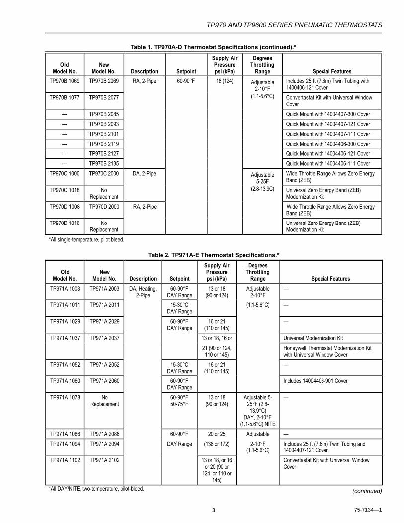
See Tables 1 though 6 for additional specifications. Thesetables represent the direct replacements of existingthermostats at the time of the introduction of the 2000 seriesof thermostats. For replacement parts, see PARTS andACCESSORIES.
Table 1. TP970A-D Thermostat Specifications.*
OldModel No.
NewModel No. Description Setpoint
Supply AirPressurepsi (kPa)
DegreesThrottling
Range Special Features
TP970A 1004 TP970A 2004 DA, 60-90°F 18 (124) Adjustable —
TP970A 1012 TP970A 2012 2-Pipe 4079°F 2-10°F —
TP970A 1020 TP970A 2020 15-30°C (1.1-5.6°C) —
TP970A 1038 TP970A 2038 60-90°F Universal Modernization Kit with UniversalWindow Cover
TP970A 1053 TP970A 2053 Honeywell Thermostat Modernization Kitwith Universal Window Cover
TP970A 1062 NoReplacement
60-90°FControls at
72°F Maximum
Limited Control Range (LCR)
TP970A 1087 TP970A 2087 60-72°F Universal Modernization Kit with UniversalWindow Cover
TP970A 1095 TP970A 2095 40-70°F Universal Modernization Kit with UniversalWindow Cover
TP970A 1103 TP970A 2103 60-90°F Includes 25 ft (7.6m) Twin Tubing and14004407-300 Cover
TP970A 1111 TP970A 2111 Includes 25 ft (7.6m) Twin Tubing and14004407-121 Cover
TP970A 1129 TP970A 2129 Includes 25 ft (7.6m) Sheathed Tubing and14004406-300 Cover
TP970A 1137 TP970A 2137 Includes 25 ft (7.6m) Sheathed Tubing and14004406-121 Cover
TP970A 1145 TP970A 2145 Convertastat Kit with Universal WindowCover. Replacement for 2-pipe only; Johnson T4002 & T4100,Powers TH192, Robertshaw TP2211 &TP2212
— TP970A 2152 Quick Mount with 14004407-300 Cover
— TP970A 2160 Quick Mount with 14004407-121 Cover
— TP970A 2178 Quick Mount with 14004407-111 Cover
— TP970A 2186 Quick Mount with 14004406-300 Cover
— TP970A 2194 Quick Mount with 14004406-121 Cover
— TP970A 2202 Quick Mount with 14004406-111 Cover
TP970B 1002 TP970B 2002 RA, 2-Pipe —
TP970B 1010 TP970B 2010 15-30°C —
TP970B 1028 TP970B 2028 60-90°F Universal Modernization Kit with UniversalWindow Cover
TP970B 1036 TP970B 2036 Honeywell Thermostat Modernization Kitwith Universal Window Cover
TP970B 1044 NoReplacement
60-90°FControls at
78°F Minimum
Limited Control Range (LCR)
*All single-temperature, pilot bleed.
TP970 AND TP9600 SERIES PNEUMATIC THERMOSTATS
3 75-7134—1
Table 1. TP970A-D Thermostat Specifications (continued).*
Table 2. TP971A-E Thermostat Specifications.*
(continued)
OldModel No.
NewModel No. Description Setpoint
Supply AirPressurepsi (kPa)
DegreesThrottling
Range Special Features
TP970B 1069 TP970B 2069 RA, 2-Pipe 60-90°F 18 (124) Adjustable2-10°F
Includes 25 ft (7.6m) Twin Tubing with1400406-121 Cover
TP970B 1077 TP970B 2077 (1.1-5.6°C) Convertastat Kit with Universal WindowCover
— TP970B 2085 Quick Mount with 14004407-300 Cover
— TP970B 2093 Quick Mount with 14004407-121 Cover
— TP970B 2101 Quick Mount with 14004407-111 Cover
— TP970B 2119 Quick Mount with 14004406-300 Cover
— TP970B 2127 Quick Mount with 14004406-121 Cover
— TP970B 2135 Quick Mount with 14004406-111 Cover
TP970C 1000 TP970C 2000 DA, 2-Pipe Adjustable5-25F
Wide Throttle Range Allows Zero EnergyBand (ZEB)
TP970C 1018 NoReplacement
(2.8-13.9C) Universal Zero Energy Band (ZEB)Modernization Kit
TP970D 1008 TP970D 2000 RA, 2-Pipe Wide Throttle Range Allows Zero EnergyBand (ZEB)
TP970D 1016 NoReplacement
Universal Zero Energy Band (ZEB)Modernization Kit
*All single-temperature, pilot bleed.
OldModel No.
NewModel No. Description Setpoint
Supply AirPressurepsi (kPa)
DegreesThrottling
Range Special Features
TP971A 1003 TP971A 2003 DA, Heating,2-Pipe
60-90°FDAY Range
13 or 18(90 or 124)
Adjustable2-10°F
—
TP971A 1011 TP971A 2011 15-30°CDAY Range
(1.1-5.6°C) —
TP971A 1029 TP971A 2029 60-90°FDAY Range
16 or 21(110 or 145)
—
TP971A 1037 TP971A 2037 13 or 18, 16 or Universal Modernization Kit
21 (90 or 124,110 or 145)
Honeywell Thermostat Modernization Kitwith Universal Window Cover
TP971A 1052 TP971A 2052 15-30°CDAY Range
16 or 21(110 or 145)
—
TP971A 1060 TP971A 2060 60-90°FDAY Range
Includes 14004406-901 Cover
TP971A 1078 NoReplacement
60-90°F50-75°F
13 or 18(90 or 124)
Adjustable 5-25°F (2.8-13.9°C)
DAY, 2-10°F(1.1-5.6°C) NITE
—
TP971A 1086 TP971A 2086 60-90°F 20 or 25 Adjustable —
TP971A 1094 TP971A 2094 DAY Range (138 or 172) 2-10°F(1.1-5.6°C)
Includes 25 ft (7.6m) Twin Tubing and14004407-121 Cover
TP971A 1102 TP971A 2102 13 or 18, or 16or 20 (90 or
124, or 110 or145)
Convertastat Kit with Universal WindowCover
*All DAY/NITE, two-temperature, pilot-bleed.

4
TP970 AND TP9600 SERIES PNEUMATIC THERMOSTATS
75-7134—1
Table 2. TP971A-E Thermostat Specifications (continued).*
OldModel No.
NewModel No. Description Setpoint
Supply AirPressurepsi (kPa)
DegreesThrottling
Range Special Features
— TP971A 2110 DA, Heating,2-Pipe
60-90°FDAY Range
13 or 18 Adjustable 2-10°F (1.1-5.6°C)
Quick Mount with 14004407-300 Cover
— TP971A 2128 (90 or 124) Quick Mount with 14004407-121 Cover
— TP971A 2136 Quick Mount with 14004407-111 Cover
— TP971A 2144 Quick Mount with 14004406-300 Cover
— TP971A 2151 Quick Mount with 14004406-121 Cover
— TP971A 2169 Quick Mount with 14004406-111 Cover
TP971B 1001 TP971B 2001 RA, —
TP971B 1019 TP971B 2019 Heating,2-Pipe
16 or 21(110 or 145)
—
TP971B 1027 TP971B 2027 15-30°CDAY Range
13 or 18(90 or 124)
—
TP971B 1035 TP971B 2035 60-90°FDAY Range
16 or 21(110 or 145)
Includes 14004406-901 Cover
TP971B 1043 TP971B 2043 20 or 25 —
TP971B 1050 TP971B 2050 (138 or 172) Includes 25 ft (7.6m) Twin Tubing with14004407-121 Cover
TP971C 1009 TP971C 2009 DA, 13 or 18, With Secondary Branch
TP971C 1017 TP971C 2017 Heating,3-Pipe
15-30°CDAY Range
(90 or 124)
TP971C 1025 TP971C 2025 DA,Cooling,
60-90°FDAY Range
16 or 21(110 or 145)
TP971C 1041 TP971C 2041 3-Pipe 20 or 25
TP971D 1007 TP971D 2007 DA, Cooling,2-Pipe
(138 or 172) NITE Set-Up (75 to 100F)
TP971E 1004 TP971E 2004 RA, Cooling,2-Pipe
13 or 18(90 or 124)
*All DAY/NITE, two-temperature, pilot-bleed.
TP970 AND TP9600 SERIES PNEUMATIC THERMOSTATS
5 75-7134—1
Table 3. TP972A Thermostat Specifications.*
Action Supply Air Degrees
OldModel No.
NewModel No.
LeftBimetal
RightBimetal Setpoint
Pressurepsi (kPa)
ThrottlingRange Special Features
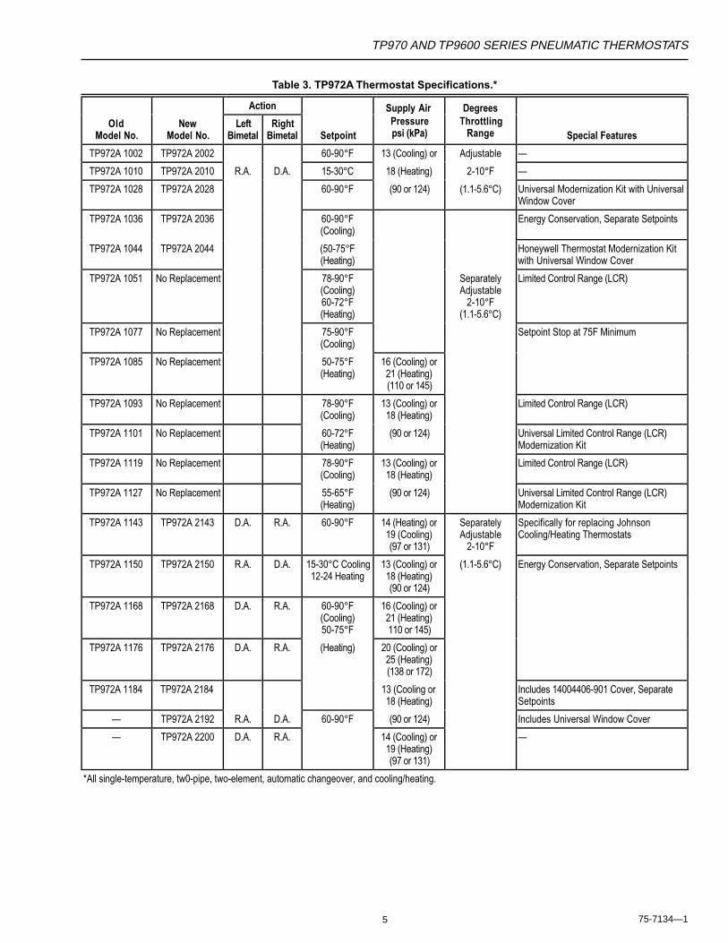
TP972A 1002 TP972A 2002 60-90°F 13 (Cooling) or Adjustable —
TP972A 1010 TP972A 2010 R.A. D.A. 15-30°C 18 (Heating) 2-10°F —
TP972A 1028 TP972A 2028 60-90°F (90 or 124) (1.1-5.6°C) Universal Modernization Kit with UniversalWindow Cover
TP972A 1036 TP972A 2036 60-90°F(Cooling)
Energy Conservation, Separate Setpoints
TP972A 1044 TP972A 2044 (50-75°F(Heating)
Honeywell Thermostat Modernization Kitwith Universal Window Cover
TP972A 1051 No Replacement 78-90°F(Cooling)60-72°F(Heating)
SeparatelyAdjustable
2-10°F(1.1-5.6°C)
Limited Control Range (LCR)
TP972A 1077 No Replacement 75-90°F(Cooling)
Setpoint Stop at 75F Minimum
TP972A 1085 No Replacement 50-75°F(Heating)
16 (Cooling) or21 (Heating)(110 or 145)
TP972A 1093 No Replacement 78-90°F(Cooling)
13 (Cooling) or18 (Heating)
Limited Control Range (LCR)
TP972A 1101 No Replacement 60-72°F(Heating)
(90 or 124) Universal Limited Control Range (LCR)Modernization Kit
TP972A 1119 No Replacement 78-90°F(Cooling)
13 (Cooling) or18 (Heating)
Limited Control Range (LCR)
TP972A 1127 No Replacement 55-65°F(Heating)
(90 or 124) Universal Limited Control Range (LCR)Modernization Kit
TP972A 1143 TP972A 2143 D.A. R.A. 60-90°F 14 (Heating) or19 (Cooling)(97 or 131)
SeparatelyAdjustable
2-10°F
Specifically for replacing JohnsonCooling/Heating Thermostats
TP972A 1150 TP972A 2150 R.A. D.A. 15-30°C Cooling12-24 Heating
13 (Cooling) or18 (Heating)(90 or 124)
(1.1-5.6°C) Energy Conservation, Separate Setpoints
TP972A 1168 TP972A 2168 D.A. R.A. 60-90°F(Cooling)50-75°F
16 (Cooling) or21 (Heating)110 or 145)
TP972A 1176 TP972A 2176 D.A. R.A. (Heating) 20 (Cooling) or25 (Heating)(138 or 172)
TP972A 1184 TP972A 2184 13 (Cooling or18 (Heating)
Includes 14004406-901 Cover, SeparateSetpoints
— TP972A 2192 R.A. D.A. 60-90°F (90 or 124) Includes Universal Window Cover
— TP972A 2200 D.A. R.A. 14 (Cooling) or19 (Heating)(97 or 131)
—
*All single-temperature, tw0-pipe, two-element, automatic changeover, and cooling/heating.
6
TP970 AND TP9600 SERIES PNEUMATIC THERMOSTATS
75-7134—1
Table 4. TP973A and B Thermostat Specifications.*
OldModel No.
NewModel No. Action Setpoint
Supply AirPressurepsi (kPa)
DegreesThrottling
Range Special Features
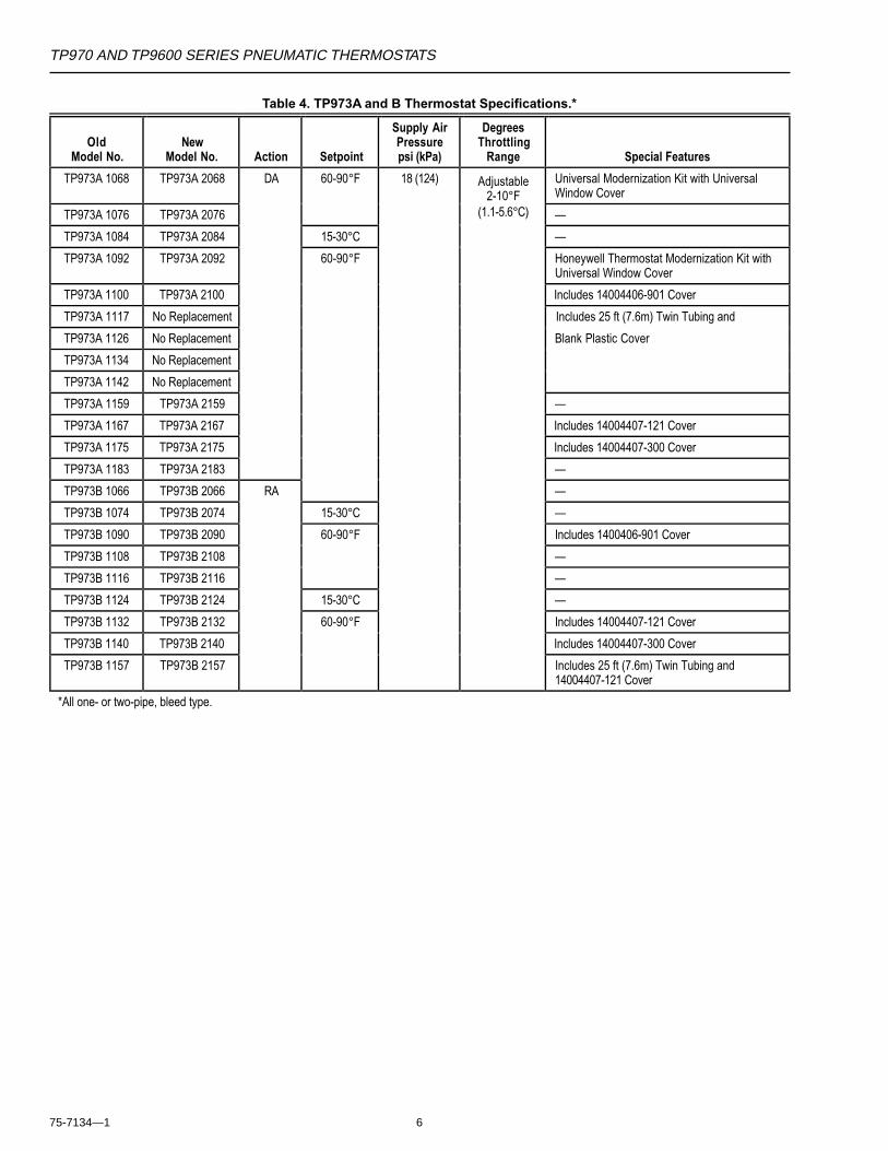
TP973A 1068 TP973A 2068 DA 60-90°F 18 (124) Adjustable2-10°F
Universal Modernization Kit with UniversalWindow Cover
TP973A 1076 TP973A 2076 (1.1-5.6°C) —
TP973A 1084 TP973A 2084 15-30°C —
TP973A 1092 TP973A 2092 60-90°F Honeywell Thermostat Modernization Kit withUniversal Window Cover
TP973A 1100 TP973A 2100 Includes 14004406-901 Cover
TP973A 1117 No Replacement Includes 25 ft (7.6m) Twin Tubing and
TP973A 1126 No Replacement Blank Plastic Cover
TP973A 1134 No Replacement
TP973A 1142 No Replacement
TP973A 1159 TP973A 2159 —
TP973A 1167 TP973A 2167 Includes 14004407-121 Cover
TP973A 1175 TP973A 2175 Includes 14004407-300 Cover
TP973A 1183 TP973A 2183 —
TP973B 1066 TP973B 2066 RA —
TP973B 1074 TP973B 2074 15-30°C —
TP973B 1090 TP973B 2090 60-90°F Includes 1400406-901 Cover
TP973B 1108 TP973B 2108 —
TP973B 1116 TP973B 2116 —
TP973B 1124 TP973B 2124 15-30°C —
TP973B 1132 TP973B 2132 60-90°F Includes 14004407-121 Cover
TP973B 1140 TP973B 2140 Includes 14004407-300 Cover
TP973B 1157 TP973B 2157 Includes 25 ft (7.6m) Twin Tubing and14004407-121 Cover
*All one- or two-pipe, bleed type.
TP970 AND TP9600 SERIES PNEUMATIC THERMOSTATS
7 75-7134—1
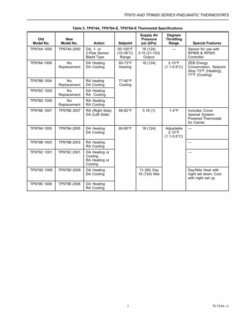
Table 5. TP974A, TP978A-E, TP979A-E Thermostat Specifications.
OldModel No.
NewModel No. Action Setpoint
Supply AirPressurepsi (kPa)
DegreesThrottling
Range Special Features
TP974A 1000 TP974A 2000 DA, 1- or2-Pipe SensorBleed Type
50-100°F(10-38°C)
Range
18 (124)3-15 (21-103)
Output
— Sensor for use withRP908 & RP920Controller
TP978A 1006 NoReplacement
DA HeatingDA Cooling
60-73°FHeating
18 (124) 2-10°F(1.1-5.6°C)
ZEB EnergyConservation, SetpointStop 73°F (Heating),77°F (Cooling)
TP978B 1004 NoReplacement
RA heatingDA Cooling
77-90°FCooling
TP978C 1002 NoReplacement
DA HeatingRA Cooling
TP978D 1000 NoReplacement
RA HeatingRA Cooling
TP978E 1007 TP978E 2007 RA (Right Side)DA (Left Side)
68-82°F 0.18 (1) 1-4°F Includes CoverSpecial System-Powered Thermostatfor Carrier
TP979A 1005 TP979A 2005 DA HeatingDA Cooling
60-90°F 18 (124) Adjustable2-10°F
(1.1-5.6°C)
—
TP979B 1003 TP979B 2003 RA HeatingRA Cooling
—
TP979C 1001 TP979C 2001 DA Heating orCoolingRA Heating orCooling
—
TP979D 1009 TP979D 2009 DA HeatingDA Cooling
13 (90) Day18 (124) Nite
Day/Nite Heat withnight set down; Coolwith night set up.
TP979E 1006 TP979E 2006 DA HeatingRA Cooling
8
TP970 AND TP9600 SERIES PNEUMATIC THERMOSTATS
75-7134—1
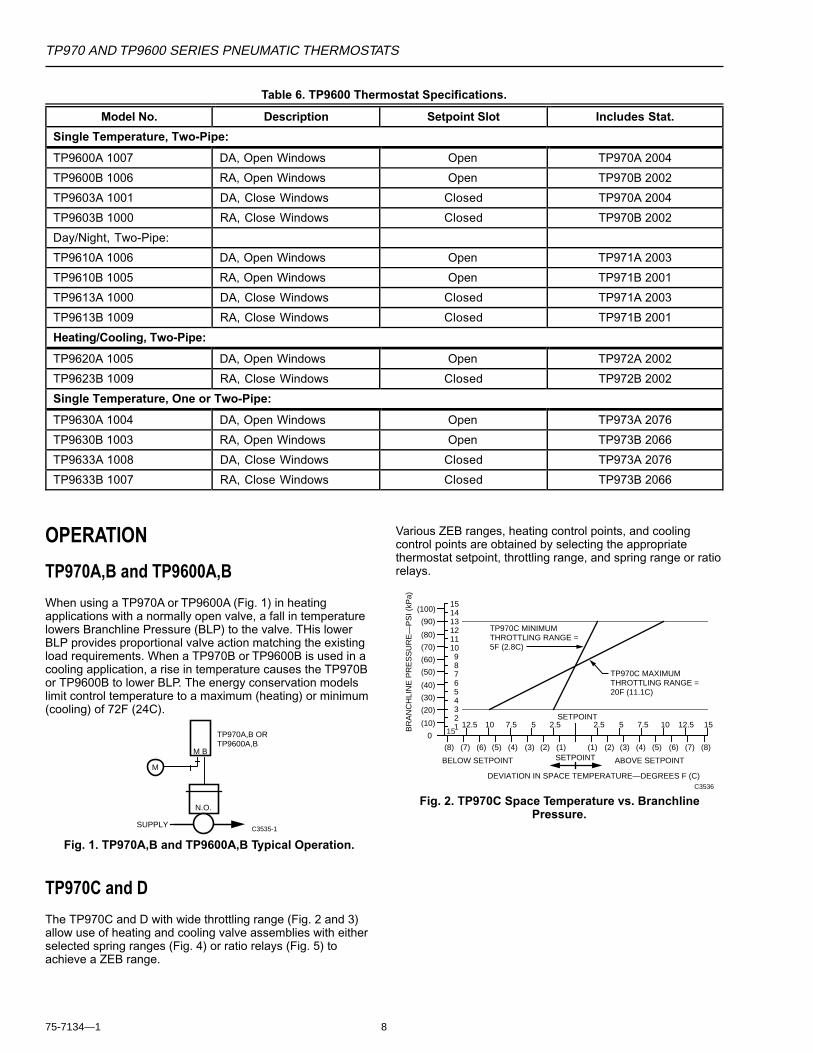
Table 6. TP9600 Thermostat Specifications.
Model No. Description Setpoint Slot Includes Stat.
Single Temperature, Two-Pipe:
TP9600A 1007 DA, Open Windows Open TP970A 2004
TP9600B 1006 RA, Open Windows Open TP970B 2002
TP9603A 1001 DA, Close Windows Closed TP970A 2004
TP9603B 1000 RA, Close Windows Closed TP970B 2002
Day/Night, Two-Pipe:
TP9610A 1006 DA, Open Windows Open TP971A 2003
TP9610B 1005 RA, Open Windows Open TP971B 2001
TP9613A 1000 DA, Close Windows Closed TP971A 2003
TP9613B 1009 RA, Close Windows Closed TP971B 2001
Heating/Cooling, Two-Pipe:
TP9620A 1005 DA, Open Windows Open TP972A 2002
TP9623B 1009 RA, Close Windows Closed TP972B 2002
Single Temperature, One or Two-Pipe:
TP9630A 1004 DA, Open Windows Open TP973A 2076
TP9630B 1003 RA, Open Windows Open TP973B 2066
TP9633A 1008 DA, Close Windows Closed TP973A 2076
TP9633B 1007 RA, Close Windows Closed TP973B 2066
OPERATION
TP970A,B and TP9600A,B
When using a TP970A or TP9600A (Fig. 1) in heatingapplications with a normally open valve, a fall in temperaturelowers Branchline Pressure (BLP) to the valve. THis lowerBLP provides proportional valve action matching the existingload requirements. When a TP970B or TP9600B is used in acooling application, a rise in temperature causes the TP970Bor TP9600B to lower BLP. The energy conservation modelslimit control temperature to a maximum (heating) or minimum(cooling) of 72F (24C).
SUPPLY
TP970A,B ORTP9600A,B
N.O.
M B
M
C3535-1
Fig. 1. TP970A,B and TP9600A,B Typical Operation.
TP970C and D
The TP970C and D with wide throttling range (Fig. 2 and 3)allow use of heating and cooling valve assemblies with eitherselected spring ranges (Fig. 4) or ratio relays (Fig. 5) toachieve a ZEB range.
Various ZEB ranges, heating control points, and coolingcontrol points are obtained by selecting the appropriatethermostat setpoint, throttling range, and spring range or ratiorelays.
151413121110987654321
(100)
(90)
(80)
(70)
(60)
(50)
(40)
(30)
(20)
(10)
0 1512.5 10 7.5 5 2.5 1512.5107.552.5
SETPOINT
SETPOINT(8) (7) (6) (5) (4) (3) (2) (1) (8)(7)(6)(5)(4)(3)(2)(1)
BR
AN
CH
LIN
E P
RE
SS
UR
E—
PS
I (kP
a)
DEVIATION IN SPACE TEMPERATURE—DEGREES F (C)
BELOW SETPOINT ABOVE SETPOINT
C3536
TP970C MINIMUM THROTTLING RANGE = 5F (2.8C)
TP970C MAXIMUM THROTTLING RANGE = 20F (11.1C)
Fig. 2. TP970C Space Temperature vs. BranchlinePressure.
TP970 AND TP9600 SERIES PNEUMATIC THERMOSTATS
9 75-7134—1
151413121110987654321
(100)
(90)
(80)
(70)
(60)
(50)
(40)
(30)
(20)
(10)
0 1512.5 10 7.5 5 2.5 1512.5107.552.5
SETPOINT
SETPOINT(8) (7) (6) (5) (4) (3) (2) (1) (8)(7)(6)(5)(4)(3)(2)(1)
BR
AN
CH
LIN
E P
RE
SS
UR
E—
PS
I (kP
a)
DEVIATION IN SPACE TEMPERATURE—DEGREES F (C)
BELOW SETPOINT ABOVE SETPOINT
C3537
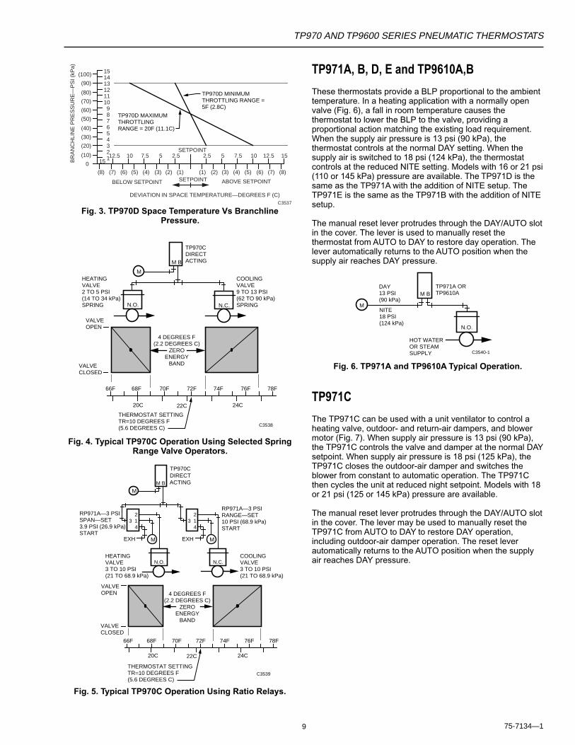
TP970D MINIMUM THROTTLING RANGE = 5F (2.8C)
TP970D MAXIMUM THROTTLING RANGE = 20F (11.1C)
Fig. 3. TP970D Space Temperature Vs BranchlinePressure.
VALVEOPEN
VALVECLOSED
4 DEGREES F (2.2 DEGREES C)
ZEROENERGY
BAND
THERMOSTAT SETTING TR=10 DEGREES F (5.6 DEGREES C)
20C 22C 24C
66F 68F 70F 72F 74F 76F 78F
TP970CDIRECTACTING
COOLINGVALVE9 TO 13 PSI(62 TO 90 kPa)SPRING
HEATINGVALVE2 TO 5 PSI(14 TO 34 kPa)SPRING N.C.N.O.
M B
M
C3538
Fig. 4. Typical TP970C Operation Using Selected SpringRange Valve Operators.
TP970CDIRECTACTING
HEATINGVALVE3 TO 10 PSI(21 TO 68.9 kPa)
COOLINGVALVE3 TO 10 PSI(21 TO 68.9 kPa)
RP971A—3 PSIRANGE—SET10 PSI (68.9 kPa)START
RP971A—3 PSISPAN—SET3.9 PSI (26.9 kPa)START
M
MM B
214
3
EXH
N.O.
M
214
3
EXH
N.C.
C3539
VALVEOPEN
VALVECLOSED
20C 22C 24C
66F 68F 70F 72F 74F 76F 78F
4 DEGREES F (2.2 DEGREES C)
ZEROENERGY
BAND
THERMOSTAT SETTING TR=10 DEGREES F (5.6 DEGREES C)
Fig. 5. Typical TP970C Operation Using Ratio Relays.
TP971A, B, D, E and TP9610A,B
These thermostats provide a BLP proportional to the ambienttemperature. In a heating application with a normally openvalve (Fig. 6), a fall in room temperature causes thethermostat to lower the BLP to the valve, providing aproportional action matching the existing load requirement.When the supply air pressure is 13 psi (90 kPa), thethermostat controls at the normal DAY setting. When thesupply air is switched to 18 psi (124 kPa), the thermostatcontrols at the reduced NITE setting. Models with 16 or 21 psi(110 or 145 kPa) pressure are available. The TP971D is thesame as the TP971A with the addition of NITE setup. TheTP971E is the same as the TP971B with the addition of NITEsetup.
The manual reset lever protrudes through the DAY/AUTO slotin the cover. The lever is used to manually reset thethermostat from AUTO to DAY to restore day operation. Thelever automatically returns to the AUTO position when thesupply air reaches DAY pressure.
TP971A ORTP9610A
DAY13 PSI(90 kPa)
NITE18 PSI(124 kPa)
M B
N.O.
M
HOT WATEROR STEAMSUPPLY C3540-1
Fig. 6. TP971A and TP9610A Typical Operation.
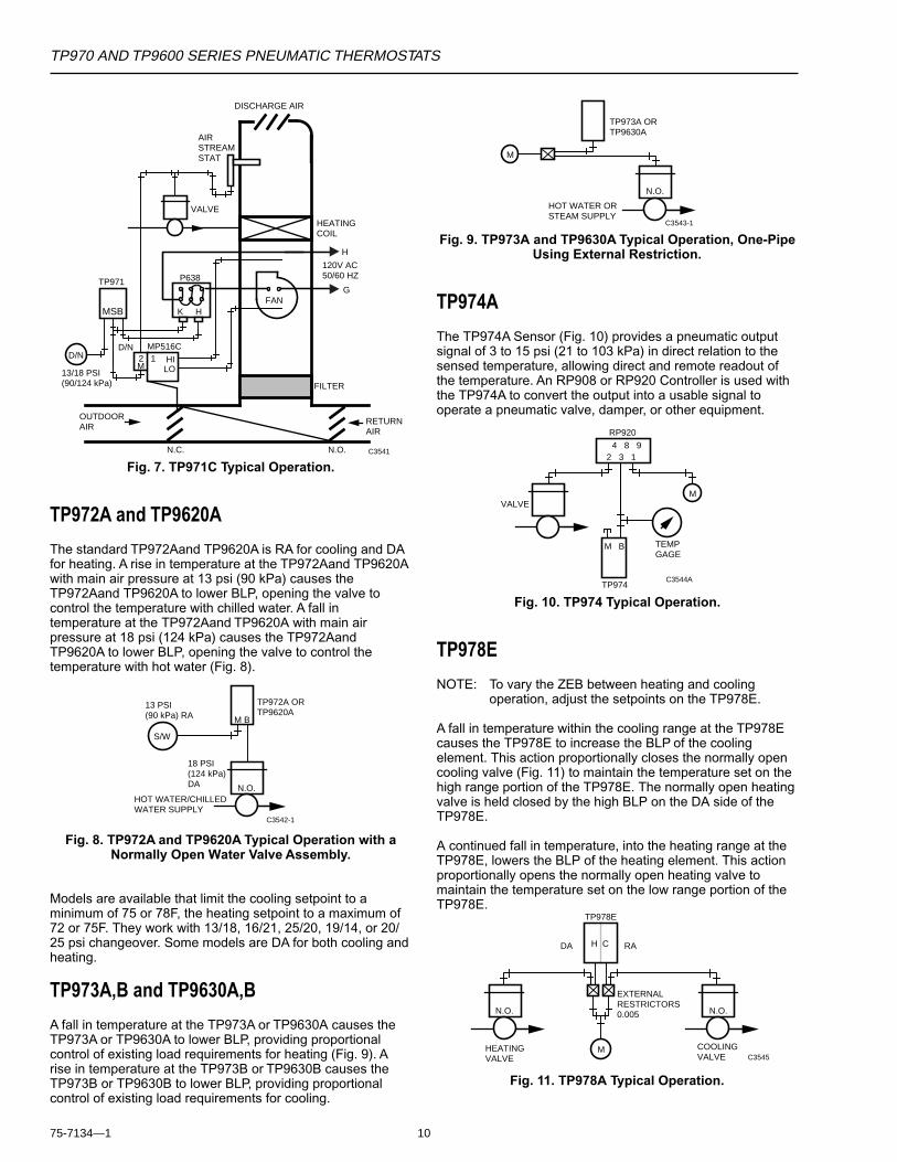
TP971C
The TP971C can be used with a unit ventilator to control aheating valve, outdoor- and return-air dampers, and blowermotor (Fig. 7). When supply air pressure is 13 psi (90 kPa),the TP971C controls the valve and damper at the normal DAYsetpoint. When supply air pressure is 18 psi (125 kPa), theTP971C closes the outdoor-air damper and switches theblower from constant to automatic operation. The TP971Cthen cycles the unit at reduced night setpoint. Models with 18or 21 psi (125 or 145 kPa) pressure are available.
The manual reset lever protrudes through the DAY/AUTO slotin the cover. The lever may be used to manually reset theTP971C from AUTO to DAY to restore DAY operation,including outdoor-air damper operation. The reset leverautomatically returns to the AUTO position when the supplyair reaches DAY pressure.
10
TP970 AND TP9600 SERIES PNEUMATIC THERMOSTATS
75-7134—1
12M
HILO
N.C. N.O.
D/N MP516C
FAN
P638G
TP971C
VALVE
HEATINGCOIL
H
120V AC50/60 HZ
AIR STREAMSTAT
13/18 PSI(90/124 kPa)
D/N
MSB K H
FILTER
DISCHARGE AIR
OUTDOORAIR
RETURNAIR
C3541
Fig. 7. TP971C Typical Operation.
TP972A and TP9620A
The standard TP972Aand TP9620A is RA for cooling and DAfor heating. A rise in temperature at the TP972Aand TP9620Awith main air pressure at 13 psi (90 kPa) causes theTP972Aand TP9620A to lower BLP, opening the valve tocontrol the temperature with chilled water. A fall intemperature at the TP972Aand TP9620A with main airpressure at 18 psi (124 kPa) causes the TP972AandTP9620A to lower BLP, opening the valve to control thetemperature with hot water (Fig. 8).
TP972A ORTP9620A
13 PSI(90 kPa) RA
18 PSI(124 kPa)DA N.O.
M B
S/W
HOT WATER/CHILLEDWATER SUPPLY
C3542-1
Fig. 8. TP972A and TP9620A Typical Operation with aNormally Open Water Valve Assembly.
Models are available that limit the cooling setpoint to aminimum of 75 or 78F, the heating setpoint to a maximum of72 or 75F. They work with 13/18, 16/21, 25/20, 19/14, or 20/25 psi changeover. Some models are DA for both cooling andheating.
TP973A,B and TP9630A,B
A fall in temperature at the TP973A or TP9630A causes theTP973A or TP9630A to lower BLP, providing proportionalcontrol of existing load requirements for heating (Fig. 9). Arise in temperature at the TP973B or TP9630B causes theTP973B or TP9630B to lower BLP, providing proportionalcontrol of existing load requirements for cooling.
Fig. 9. TP973A and TP9630A Typical Operation, One-PipeUsing External Restriction.
TP974A
The TP974A Sensor (Fig. 10) provides a pneumatic outputsignal of 3 to 15 psi (21 to 103 kPa) in direct relation to thesensed temperature, allowing direct and remote readout ofthe temperature. An RP908 or RP920 Controller is used withthe TP974A to convert the output into a usable signal tooperate a pneumatic valve, damper, or other equipment.
TP973A ORTP9630A
M
N.O.
HOT WATER ORSTEAM SUPPLY
C3543-1
TP974
VALVE
TEMPGAGE
4 8 92 3 1
M
RP920
C3544A
M B
Fig. 10. TP974 Typical Operation.
TP978E
NOTE: To vary the ZEB between heating and coolingoperation, adjust the setpoints on the TP978E.
A fall in temperature within the cooling range at the TP978Ecauses the TP978E to increase the BLP of the coolingelement. This action proportionally closes the normally opencooling valve (Fig. 11) to maintain the temperature set on thehigh range portion of the TP978E. The normally open heatingvalve is held closed by the high BLP on the DA side of theTP978E.
A continued fall in temperature, into the heating range at theTP978E, lowers the BLP of the heating element. This actionproportionally opens the normally open heating valve tomaintain the temperature set on the low range portion of theTP978E.
DA RA
TP978E
MHEATINGVALVE
COOLINGVALVE
H C
N.O. N.O.
C3545
EXTERNALRESTRICTORS0.005
Fig. 11. TP978A Typical Operation.
TP970 AND TP9600 SERIES PNEUMATIC THERMOSTATS
11 75-7134—1
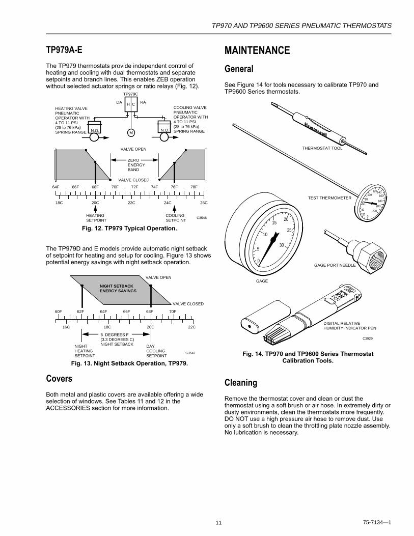
TP979A-E
The TP979 thermostats provide independent control ofheating and cooling with dual thermostats and separatesetpoints and branch lines. This enables ZEB operationwithout selected actuator springs or ratio relays (Fig. 12).
64F 66F 68F 70F 72F 74F 76F 78F
18C 20C 22C 24C 26C
ZEROENERGYBAND
VALVE CLOSED
HEATINGSETPOINT
COOLINGSETPOINT
VALVE OPEN
TP979C
COOLING VALVEPNEUMATICOPERATOR WITH4 TO 11 PSI(28 to 76 kPa)SPRING RANGE
HEATING VALVEPNEUMATICOPERATOR WITH4 TO 11 PSI(28 to 76 kPa)SPRING RANGE N.O. N.O.
H C
M
DA RA
C3546
Fig. 12. TP979 Typical Operation.
The TP979D and E models provide automatic night setbackof setpoint for heating and setup for cooling. Figure 13 showspotential energy savings with night setback operation.
VALVE CLOSED
NIGHTHEATINGSETPOINT
DAYCOOLINGSETPOINT
VALVE OPEN
64F 66F 68F 70F60F 62F
18C 20C 22C16C
6 DEGREES F(3.3 DEGREES C)NIGHT SETBACK
NIGHT SETBACKENERGY SAVINGS
C3547
Fig. 13. Night Setback Operation, TP979.
Covers
Both metal and plastic covers are available offering a wideselection of windows. See Tables 11 and 12 in theACCESSORIES section for more information.
MAINTENANCE
General
See Figure 14 for tools necessary to calibrate TP970 andTP9600 Series thermostats.
Fig. 14. TP970 and TP9600 Series ThermostatCalibration Tools.
Cleaning
Remove the thermostat cover and clean or dust thethermostat using a soft brush or air hose. In extremely dirty ordusty environments, clean the thermostats more frequently.DO NOT use a high pressure air hose to remove dust. Useonly a soft brush to clean the throttling plate nozzle assembly.No lubrication is necessary.
C3929
GAGE PORT NEEDLE
DIGITAL RELATIVEHUMIDITY INDICATOR PEN
100120140
160
1808060
200
2204020
0
1025
30
2015
5
0
GAGE
TEST THERMOMETER
THERMOSTAT TOOL
12
TP970 AND TP9600 SERIES PNEUMATIC THERMOSTATS
75-7134—1
Calibration
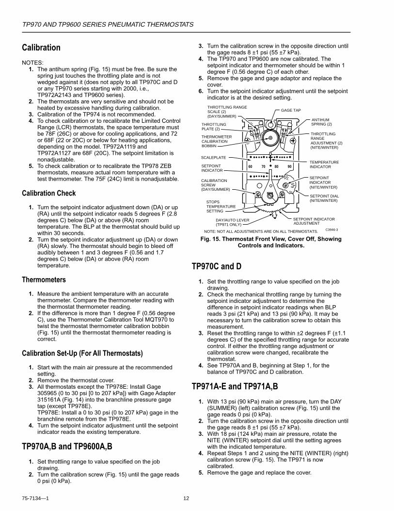
NOTES:1. The antihum spring (Fig. 15) must be free. Be sure the
spring just touches the throttling plate and is notwedged against it (does not apply to all TP970C and Dor any TP970 series starting with 2000, i.e.,TP972A2143 and TP9600 series).
2. The thermostats are very sensitive and should not beheated by excessive handling during calibration.
3. Calibration of the TP974 is not recommended.4. To check calibration or to recalibrate the Limited Control
Range (LCR) thermostats, the space temperature mustbe 78F (26C) or above for cooling applications, and 72or 68F (22 or 20C) or below for heating applications,depending on the model. TP972A1119 andTP972A1127 are 68F (20C). The setpoint limitation isnonadjustable.
5. To check calibration or to recalibrate the TP978 ZEBthermostats, measure actual room temperature with atest thermometer. The 75F (24C) limit is nonadjustable.
Calibration Check
1. Turn the setpoint indicator adjustment down (DA) or up(RA) until the setpoint indicator reads 5 degrees F (2.8degrees C) below (DA) or above (RA) roomtemperature. The BLP at the thermostat should build upwithin 30 seconds.
2. Turn the setpoint indicator adjustment up (DA) or down(RA) slowly. The thermostat should begin to bleed offaudibly between 1 and 3 degrees F (0.56 and 1.7degrees C) below (DA) or above (RA) roomtemperature.
Thermometers
1. Measure the ambient temperature with an accuratethermometer. Compare the thermometer reading withthe thermostat thermometer reading.
2. If the difference is more than 1 degree F (0.56 degreeC), use the Thermometer Calibration Tool MQT970 totwist the thermostat thermometer calibration bobbin(Fig. 15) until the thermostat thermometer reading iscorrect.
Calibration Set-Up (For All Thermostats)
1. Start with the main air pressure at the recommendedsetting.
2. Remove the thermostat cover.3. All thermostats except the TP978E: Install Gage
305965 (0 to 30 psi [0 to 207 kPa]) with Gage Adapter315161A (Fig. 14) into the branchline pressure gagetap (except TP978E).TP978E: Install a 0 to 30 psi (0 to 207 kPa) gage in thebranchline remote from the TP978E.
4. Turn the setpoint indicator adjustment until the setpointindicator reads the existing temperature.
TP970A,B and TP9600A,B
1. Set throttling range to value specified on the jobdrawing.
2. Turn the calibration screw (Fig. 15) until the gage reads0 psi (0 kPa).
3. Turn the calibration screw in the opposite direction untilthe gage reads 8 ±1 psi (55 ±7 kPa).
4. The TP970 and TP9600 are now calibrated. Thesetpoint indicator and thermometer should be within 1degree F (0.56 degree C) of each other.
5. Remove the gage and gage adaptor and replace thecover.
6. Turn the setpoint indicator adjustment until the setpointindicator is at the desired setting.
7060 80 90
ANTIHUM SPRING (2)
THROTTLINGRANGEADJUSTMENT (2)(NITE/WINTER)
SETPOINT DIAL(NITE/WINTER)
THERMOMETERCALIBRATIONBOBBIN
SETPOINTINDICATOR(NITE/WINTER)
SETPOINTINDICATOR
CALIBRATIONSCREW(DAY/SUMMER)
DAY/AUTO LEVER(TP971 ONLY)
SETPOINT INDICATORADJUSTMENT
C3946-3
5
5
56
7
SCALEPLATE
MAX MAX
THROTTLING RANGESCALE (2) (DAY/SUMMER)
THROTTLINGPLATE (2)
GAGE TAP
NOTE: NOT ALL ADJUSTMENTS ARE ON ALL THERMOSTATS.
TEMPERATUREINDICATOR
STOPSTEMPERATURESETTING
Fig. 15. Thermostat Front View, Cover Off, ShowingControls and Indicators.
TP970C and D
1. Set the throttling range to value specified on the jobdrawing.
2. Check the mechanical throttling range by turning thesetpoint indicator adjustment to determine thedifference in setpoint indicator readings when BLPreads 3 psi (21 kPa) and 13 psi (90 kPa). It may benecessary to turn the calibration screw to obtain thismeasurement.
3. Reset the throttling range to within ±2 degrees F (±1.1degrees C) of the specified throttling range for accuratecontrol. If either the throttling range adjustment orcalibration screw were changed, recalibrate thethermostat.
4. See TP970A and B, beginning at Step 1, for thebalance of TP970C and D calibration.
TP971A-E and TP971A,B
1. With 13 psi (90 kPa) main air pressure, turn the DAY(SUMMER) (left) calibration screw (Fig. 15) until thegage reads 0 psi (0 kPa).
2. Turn the calibration screw in the opposite direction untilthe gage reads 8 ±1 psi (55 ±7 kPa).
3. With 18 psi (124 kPa) main air pressure, rotate theNITE (WINTER) setpoint dial until the setting agreeswith the indicated temperature.
4. Repeat Steps 1 and 2 using the NITE (WINTER) (right)calibration screw (Fig. 15). The TP971 is nowcalibrated.
5. Remove the gage and replace the cover.
TP970 AND TP9600 SERIES PNEUMATIC THERMOSTATS
13 75-7134—1
TP972A and TP9620A
1. With 13 psi (90 kPa) main air pressure, turn the DAY(SUMMER) (left) calibration screw (Fig. 15) until thegage reads 0 psi (0 kPa).
2. Turn the calibration screw in the opposite direction untilthe gage reads 8 ±1 psi (55 ±7 kPa).
3. With 18 psi (124 kPa) main air pressure, repeat Steps 1and 2 using the NITE (WINTER) (right) calibrationscrew (Fig. 15). The TP972 and TP9620 are nowcalibrated.
4. Remove the gage and replace the cover.
TP973A,B and TP9630A,B
If the TP973A, B and TP9630A,B are not properly calibratedbut the remainder of the system is operating properly, turn thecalibration screw until the TP973A, B or TP9630A,B performsas in Step 2 under CALIBRATION CHECK.
TP974A
Field calibration of the TP974A is not recommended.
TP978A-E
If a TP978 thermostat is not properly calibrated but theremainder of the system is operating properly, turn thecalibration screw until the thermostat performs as in Step 2under CALIBRATION CHECK.
TP979A-C
1. Turn the calibration screw (Fig. 15) until the gage reads0 psi (0 kPa).
2. Turn the calibration screw in the opposite direction untilthe gage reads 8 ±1 psi (55 ±7 kPa).
3. The thermostat is now calibrated. The setpoint indicatorand thermometer should be within 1 degree F (0.56degree C) of each other.
4. Remove the gage and gage adaptor and replace thecover.
5. Turn the setpoint indicator adjustment until the setpointindicator is at the desired setting.
TP979D and E
1. With 13 psi (90 kPa) main line pressure, turn the DAY(SUMMER) (left) calibration screw (Fig. 15) until thegage reads 0 psi (0 kPa).
2. Turn the calibration screw in the opposite direction untilthe gage reads 8 ±1 psi (55 ±7 kPa).
3. With 18 psi (124 kPa) main air pressure, rotate thenight setpoint dial until the setting agrees with theindicated temperature.
4. Repeat Steps 1 and 2 using the NITE (WINTER) (right)calibration screw (Fig. 15). The thermostat is nowcalibrated.
5. Remove the gage and replace cover.
Switchover Calibration
Switchover allows for normal supply line fluctuations.
TP971A-E and TP9610A,B1. Ensure that main line pressure is set to low (13 psi)
pressure requirement.2. Turn the setpoint indicator adjustment until the setpoint
indicator reads 5 degrees F (2.8 degrees C) belowactual temperature.
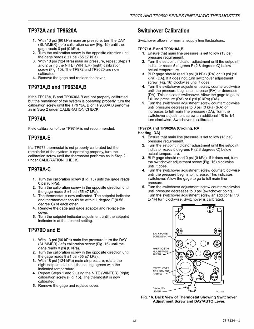
3. BLP gage should read 0 psi (0 kPa) (RA) or 13 psi (90kPa) (DA). If it does not, turn switchover adjustmentscrew (Fig. 16) clockwise until it does.
4. Turn the switchover adjustment screw counterclockwiseuntil the pressure begins to increase (RA) or decrease(DA). This indicates switchover. Allow the gage to go tofull line pressure (RA) or 0 psi (0 kPa) (DA).
5. Turn the switchover adjustment screw counterclockwiseuntil pressure decreases to 0 psi (0 kPa) (RA) orincreases to full main line pressure (DA). Turn theswitchover adjustment screw an additional 1/8 to 1/4turn clockwise. Switchover is calibrated.
TP972A and TP9620A (Cooling, RA;Heating, DA)
1. Ensure that main line pressure is set to low (13 psi)pressure requirement.
2. Turn the setpoint indicator adjustment until the setpointindicator reads 5 degrees F (2.8 degrees C) belowactual temperature.
3. BLP gage should read 0 psi (0 kPa). If it does not, turnthe switchover adjustment screw (Fig. 16) clockwiseuntil it does.
4. Turn the switchover adjustment screw counterclockwiseuntil the pressure begins to increase. This indicatesswitchover. Allow the gage to go to full main linepressure.
5. Turn the switchover adjustment screw counterclockwiseuntil pressure decreases to 0 psi (switchover point).Turn the switchover adjustment screw an additional 1/8to 1/4 turn clockwise. Switchover is calibrated.
M
P
B
M12211
BACK PLATESCREWS (4)
THERMOSTATMULTISTAGE FILTER
SWITCHOVERADJUSTMENT SCREW
DAY/AUTOLEVER
Fig. 16. Back View of Thermostat Showing SwitchoverAdjustment Screw and DAY/AUTO Lever.
14
TP970 AND TP9600 SERIES PNEUMATIC THERMOSTATS
75-7134—1
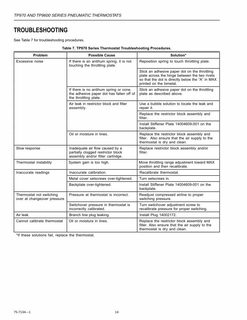
TROUBLESHOOTINGSee Table 7 for troubleshooting procedures.
Table 7. TP970 Series Thermostat Troubleshooting Procedures.
Problem Possible Cause Solution*
Excessive noise If there is an antihum spring, it is nottouching the throttling plate.
Reposition spring to touch throttling plate.
Stick an adhesive paper dot on the throttlingplate across the hinge between the two rivetsso that the dot is directly below the “A” in MAXprinted on the bimetal.
If there is no antihum spring or cone,the adhesive paper dot has fallen off ofthe throttling plate.
Stick an adhesive paper dot on the throttlingplate as described above.
Air leak in restrictor block and filterassembly.
Use a bubble solution to locate the leak andrepair it.
Replace the restrictor block assembly andfilter.
Install Stiffener Plate 14004609-001 on thebackplate.
Oil or moisture in lines. Replace the restrictor block assembly andfilter. Also ensure that the air supply to thethermostat is dry and clean.
Slow response Inadequate air flow caused by apartially clogged restrictor blockassembly and/or filter cartridge.
Replace restrictor block assembly and/orfilter.
Thermostat instability System gain is too high. Move throttling range adjustment toward MAXposition and then recalibrate.
Inaccurate readings Inaccurate calibration. Recalibrate thermostat.
Metal cover setscrews over-tightened. Turn setscrews in.
Backplate over-tightened. Install Stiffener Plate 14004609-001 on thebackplate.
Thermostat not switchingover at changeover pressure
Pressure at thermostat is incorrect. Readjust compressed airline to properswitching pressure.
Switchover pressure in thermostat isincorrectly calibrated.
Turn switchover adjustment screw torecalibrate pressure for proper switching.
Air leak Branch line plug leaking. Install Plug 14002172.
Cannot calibrate thermostat Oil or moisture in lines. Replace the restrictor block assembly andfilter. Also ensure that the air supply to thethermostat is dry and clean.
*If these solutions fail, replace the thermostat.
TP970 AND TP9600 SERIES PNEUMATIC THERMOSTATS
15 75-7134—1
REPAIR
Thermometer Replacement
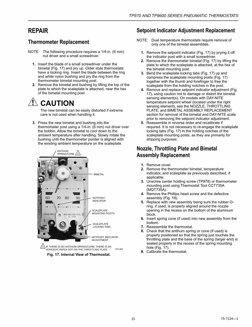
NOTE: The following procedure requires a 1/4-in. (6 mm)nut driver and a small screwdriver.
1. Insert the blade of a small screwdriver under thebimetal (Fig. 17) and pry up. Older style thermostatshave a locking ring. Insert the blade between the ringand white nylon bushing and pry the ring from thethermometer bimetal mounting post.
2. Remove the bimetal and bushing by lifting the top of theplate to which the scaleplate is attached, near the hexof the bimetal mounting post.
CAUTIONThe new bimetal can be easily distorted if extremecare is not used when handling it.
3. Press the new bimetal and bushing into thethermometer post using a 1/4-in. (6 mm) nut driver overthe bobbin. Allow the bimetal to cool down to theambient temperature after handling. Slowly rotate thebushing until the thermometer pointer is aligned withthe existing ambient temperature on the scaleplate.
ANTIHUMSPRING/CONE
BIMETAL
SETPOINTINDICATOR
SCALEPLATEMOUNTING POSTS
SCALEPLATELOCKING TABS
SETPOINT INDICATORADJUSTMENT
IF THERE IS NO ANTIHUM SPRING/CONE, THERE IS ANADHESIVE PAPER DOT ON THE THROTTLING PLATE.
1
1M11384
Fig. 17. Internal View of Thermostat.
Setpoint Indicator Adjustment Replacement
NOTE: Dual temperature thermostats require removal ofonly one of the bimetal assemblies.
1. Remove the setpoint indicator (Fig. 17) by prying it offthe indicator post with a small screwdriver.
2. Remove the thermometer bimetal (Fig. 17) by lifting theplate to which the scaleplate is attached, at the hex ofthe bimetal mounting post.
3. Bend the scaleplate locking tabs (Fig. 17) up andcompress the scaleplate mounting posts (Fig. 17)together with the thumb and forefinger to free thescaleplate from the holding notches in the post.
4. Remove and replace setpoint indicator adjustment (Fig.17), using caution not to damage or distort the bimetalsensing element(s). On models with DAY-NITEtemperature setpoint wheel (located under the rightsensing element), see the NOZZLE, THROTTLINGPLATE, and BIMETAL ASSEMBLY REPLACEMENTsection for removal of the bimetal and DAY-NITE scaleprior to removing the setpoint indicator adjustment.
5. Reassemble in reverse order and recalibrate ifrequired. It is not necessary to re-engage the scaleplatelocking tabs (Fig. 17) in the holding notches of thescaleplate mounting posts, as they are primarily forshipping purposes.
Nozzle, Throttling Plate and BimetalAssembly Replacement
1. Remove cover.2. Remove the thermometer bimetal, temperature
indicator, and scaleplate as previously described, ifapplicable.
3. Unscrew center holding screw (TP978) or thermometermounting post using Thermostat Tool CCT735A(MQT735A).
4. Remove the Phillips head screw and the defectiveassembly (Fig. 18).
5. Replace with new assembly being sure the rubber O-ring, if used, is properly aligned around the nozzleopening in the recess on the bottom of the aluminumblock.
6. Insert spring cone (if used) into new assembly from thebottom.
7. Reassemble the thermostat.8. Check that the antihum spring or cone (if used) is
properly positioned so that the spring just touches thethrottling plate and the base of the spring (larger end) isseated properly in the recess of the spring mountinghole (Fig. 17).
9. Calibrate the thermostat.

16
TP970 AND TP9600 SERIES PNEUMATIC THERMOSTATS
75-7134—1
O-RING
NOZZLE, THROTTLING PLATE AND BIMETAL ASSEMBLY
NOZZLE, THROTTLING PLATE AND BIMETAL ASSEMBLY M12208
BOTTOM VIEW OF BIMETAL ASSEMBLY
SCREW
SCREW
ANTIHUM SPRING OR CONE
SCREW
IF THERE IS NO ANTIHUM SPRING/CONE, THERE IS AN ADHESIVE PAPER DOT ON THE THROTTLING PLATE.
TYPICAL POST
SETPOINT CAM ASSEMBLY
TYPICAL PNEUMATIC ASSEMBLY
SPRING
1
1
Fig. 18. Nozzle, Throttling Plate, Bimetal Assembly Replacement.
Restrictor Block and Filter Replacement
CAUTIONWhen replacing these parts, use extreme caution toprevent dirt, dust, or chips from entering variouschambers and openings of the thermostat.
1. Remove the four Phillips head screws which fasten therestrictor block and filter (Fig. 19) to the back of thethermostat.
2. Carefully remove the restrictor block assembly (plate,restrictor, filter, gasket[s]).
3. Replace the restrictor block and filter.a. Align the appropriate gasket over the
corresponding holes in the thermostat.b. Insert the filter into the gasket until it bottoms.c. Position the restrictor block.d. Align the other gasket on the restrictor block.e. Position the plate.f. Replace screws and tighten.
GASKET
TYPICAL PNEUMATIC ASSEMBLY
FILTER
RESTRICTOR
GASKET
PLATE
SCREW
M12206
Fig. 19. Restrictor Block and Filter Replacement.
TP970 AND TP9600 SERIES PNEUMATIC THERMOSTATS
17 75-7134—1
M12205
SPRING
LEVER
COVER PLATE
CAUTION:THIS PIN IS FREE TO DROP OUT WHENLEVER IS RELEASED.
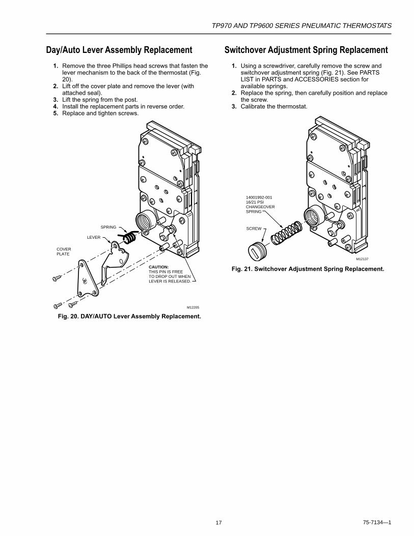
Day/Auto Lever Assembly Replacement
1. Remove the three Phillips head screws that fasten thelever mechanism to the back of the thermostat (Fig.20).
2. Lift off the cover plate and remove the lever (withattached seal).
3. Lift the spring from the post.4. Install the replacement parts in reverse order.5. Replace and tighten screws.
M12137
14001992-001 16/21 PSI CHANGEOVER SPRING
SCREW
Fig. 20. DAY/AUTO Lever Assembly Replacement.
Switchover Adjustment Spring Replacement
1. Using a screwdriver, carefully remove the screw andswitchover adjustment spring (Fig. 21). See PARTSLIST in PARTS and ACCESSORIES section foravailable springs.
2. Replace the spring, then carefully position and replacethe screw.
3. Calibrate the thermostat.
Fig. 21. Switchover Adjustment Spring Replacement.

18
TP970 AND TP9600 SERIES PNEUMATIC THERMOSTATS
75-7134—1
PARTS AND ACCESSORIES
Parts List
TP970-TP974 and TP9600-TP9630
See Figures 22 and 23, and Table 8 for TP970-TP974 andTP9600-TP9630 Thermostat repair parts and assemblies.
1
6
1A
1B
1C
1D
7
8
9
10B
10*
10C
10D
11
12
2
1
M12210
2
REPLACE THE SETPOINT CAM ASSEMBLY AND NOZZLE, THROTTLING PLATE, AND BIMETAL ASSEMBLY TOGETHER.
IF THERE IS NO ANTIHUM SPRING/CONE, THERE IS AN ADHESIVE PAPER DOT ON THE THROTTLING PLATE.
1
1
2
10F
10E
10
*BOTTOM VIEW OF
1
5
6
6
10A
1A
1B
1C
1D
7
8
9
10
10B
10
10C
10D
11
12
2
3
4
1
M12209
2
REPLACE THE SETPOINT CAM ASSEMBLY AND NOZZLE, THROTTLING PLATE, AND BIMETAL ASSEMBLY TOGETHER.
IF THERE IS NO ANTIHUM SPRING/CONE, THERE IS AN ADHESIVE PAPER DOT ON THE THROTTLING PLATE.
1
1
1
2
Fig. 22. Single Element Thermostat Exploded ViewShowing Repair Parts and Assemblies.
Fig. 23. Dual Element Thermostat Exploded ViewShowing Repair Parts and Assemblies.
TP970 AND TP9600 SERIES PNEUMATIC THERMOSTATS
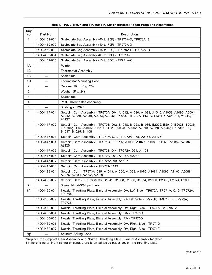
19 75-7134—1
Table 8. TP970-TP974 and TP9600-TP9630 Thermostat Repair Parts and Assemblies.
KeyNo. Part No. Description
1 14004459-001 Scaleplate Bag Assembly (60 to 90F) - TP970A-D, TP973A, B
14004459-002 Scaleplate Bag Assembly (40 to 70F) - TP970A-D
14004459-003 Scaleplate Bag Assembly (15 to 30C) - TP970A-D, TP973A, B
14004459-004 Scaleplate Bag Assembly (60 to 90F) - TP971A-E
14004459-005 Scaleplate Bag Assembly (15 to 30C) - TP971A-C
1A — Pointer
1B — Thermostat Assembly
1C — Scaleplate
1D — Thermostat Mounting Post
2 — Retainer Ring (Fig. 23)
2 — Washer (Fig. 24)
3 — Scaleplate
4 — Post, Thermostat Assembly
5 — Bushing - TP973
* 14004447-001 Setpoint Cam Assembly - TP970A1004, A1012, A1020, A1038, A1046, A1053, A1095, A2004,A2012, A2020, A2038, A2053, A2095; TP970C; TP972A1143, A2143; TP973A1001, A1019,A1127
14004447-002 Setpoint Cam Assembly - TP970B1002, B1010, B1028, B1036, B2002, B2010, B2028, B2036;TP970D; TP972A1002, A1010, A1028, A1044, A2002, A2010, A2028, A2044; TP973B1009,B1017, B1025, B1108
14004447-003 Setpoint Cam Assembly - TP971A, C, D; TP972A1168, A2168, A2176
14004447-004 Setpoint Cam Assembly - TP971B, E; TP972A1036, A1077, A1085, A1150, A1184, A2036,A2150
14004447-005 Setpoint Cam Assembly - TP970B1044; TP972A1051, A1101
14004447-006 Setpoint Cam Assembly - TP970A1061, A1087, A2087
14004447-007 Setpoint Cam Assembly - TP972A1093, A1127
14004447-008 Setpoint Cam Assembly - TP972A 1119
14004429-001 Setpoint Cam - TP973A1035, A1043, A1050, A1068, A1076, A1084, A1092, A1100, A2068,A2076, A2084, A2092, A2100
14004429-002 Setpoint Cam - TP973B1033, B1041, B1058, B1066, B1074, B1090, B2066, B2074, B2090
7 — Screw, No. 4-3/16 pan head
8* 14004460-001 Nozzle, Throttling Plate, Bimetal Assembly, DA, Left Side - TP970A; TP971A, C, D; TP972A;TP973A
14004460-002 Nozzle, Throttling Plate, Bimetal Assembly, RA Left Side - TP970B; TP971B, E; TP972A;TP973B
14004460-003 Nozzle, Throttling Plate, Bimetal Assembly, DA, Right Side - TP971A, C; TP972A
14004460-004 Nozzle, Throttling Plate, Bimetal Assembly, DA - TP970C
14004460-005 Nozzle, Throttling Plate, Bimetal Assembly, RA - TP970D
14004460-006 Nozzle, Throttling Plate, Bimetal Assembly, DA, Right Side - TP971D
14004460-007 Nozzle, Throttling Plate, Bimetal Assembly, RA, Right Side - TP971E
9† — Antihum Spring/Cone
*Replace the Setpoint Cam Assembly and Nozzle, Throttling Plate, Bimetal Assembly together.†If there is no antihum spring or cone, there is an adhesive paper dot on the throttling plate.
(continued)
20
TP970 AND TP9600 SERIES PNEUMATIC THERMOSTATS
75-7134—1
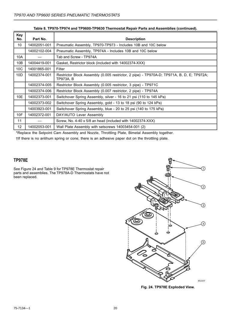
TP978E
See Figure 24 and Table 9 for TP978E Thermostat repairparts and assemblies. The TP978A-D Thermostats have notbeen replaced.
5
4
3
2
1
M12207
Fig. 24. TP978E Exploded View.
KeyNo. Part No. Description
10 14002051-001 Pneumatic Assembly, TP970-TP973 - Includes 10B and 10C below
14002102-004 Pneumatic Assembly, TP974A - Includes 10B and 10C below
10A — Tab and Screw - TP974A
10B 14004419-001 Gasket, Restrictor block (included with 14002374-XXX)
10C 14001865-001 Filter
10D 14002374-001 Restrictor Block Assembly (0.005 restrictor, 2 pipe) - TP970A-D; TP971A, B, D, E; TP972A;TP973A, B
14002374-005 Restrictor Block Assembly (0.005 restrictor, 3 pipe) - TP971C
14002374-006 Restrictor Block Assembly (0.007 restrictor, 2 pipe) - TP974A
10E 14002373-001 Switchover Spring Assembly, silver - 16 to 21 psi (110 to 145 kPa)
14002373-002 Switchover Spring Assembly, gold - 13 to 18 psi (90 to 124 kPa)
14003923-001 Switchover Spring Assembly, blue - 20 to 25 psi (140 to 175 kPa)
10F 14002372-001 DAY/AUTO Lever Assembly
11 — Screw, No. 4-40 x 5/8 an head (included with 14002374-XXX)
12 14002053-001 Wall Plate Assembly with setscrews 14003454-001 (2)
*Replace the Setpoint Cam Assembly and Nozzle, Throttling Plate, Bimetal Assembly together.
†If there is no antihum spring or cone, there is an adhesive paper dot on the throttling plate.
Table 8. TP970-TP974 and TP9600-TP9630 Thermostat Repair Parts and Assemblies (continued).

TP970 AND TP9600 SERIES PNEUMATIC THERMOSTATS
21 75-7134—1
Table 9. TP978E Thermostat Repair Parts and Assemblies.
Model
A B C D E Key No. Part No. Description
1 — Screw, No. 4 x 3/16 pan head (2)
X X 2 — Washer
X 3 14002387-004 Nozzle, Throttling Plate, Bimetal Assembly (DA, left)
X 14002098-004 Nozzle, Throttling Plate, Bimetal Assembly (RA, left)
X 14002098-005 Nozzle, Throttling Plate, Bimetal Assembly (DA, right)
4 14003855-005 Base and Cam Assembly
5 14002095-001 Mounting Plate Assembly
X X 14002387-005 left side (R.A.) 60-73
X X 14002387-006 Right side (D.A.) 77-90
X X 14002387-007 Right side (R.A.) 77-90
6070
8090
HEAT
MB1
COOL
MB2
6070
8090
3
2
1
M12221
TP979A-E
See Figure 25 and Table 10 for TP979A-E Thermostat repairparts and assemblies.
KeyNo. Part No. Description
1 14004057-001 Mounting Plate Assembly
2 14004058-001 Manifold Assembly
3 TP979A Requires two TP970A2004
TP979B Requires two TP970B2002
TP979C Requires one TP970A2004 andone TP970B2002
TP979D Requires one TP9712003 andone TP971D2007
TP979E Requires one TP971B2001 andone TP971E2004
Fig. 25. TP979 Exploded View.
Table 10. TP979A-E Thermostat Repair Partsand Assemblies.
Accessories
See TP970-TP974 and HP970 Series Fittings InstallationInstructions 95-7134 for illustrations or further information onthe following pneumatic fittings.
22
TP970 AND TP9600 SERIES PNEUMATIC THERMOSTATS
75-7134—1
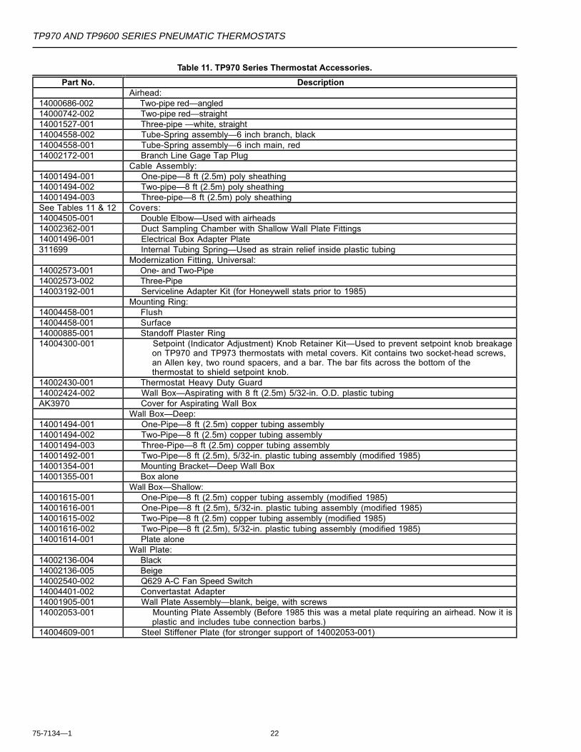
Table 11. TP970 Series Thermostat Accessories.
Part No. DescriptionAirhead:
14000686-002 Two-pipe red—angled14000742-002 Two-pipe red—straight14001527-001 Three-pipe —white, straight14004558-002 Tube-Spring assembly—6 inch branch, black14004558-001 Tube-Spring assembly—6 inch main, red14002172-001 Branch Line Gage Tap Plug
Cable Assembly:14001494-001 One-pipe—8 ft (2.5m) poly sheathing14001494-002 Two-pipe—8 ft (2.5m) poly sheathing14001494-003 Three-pipe—8 ft (2.5m) poly sheathingSee Tables 11 & 12 Covers:14004505-001 Double Elbow—Used with airheads14002362-001 Duct Sampling Chamber with Shallow Wall Plate Fittings14001496-001 Electrical Box Adapter Plate311699 Internal Tubing Spring—Used as strain relief inside plastic tubing
Modernization Fitting, Universal:14002573-001 One- and Two-Pipe14002573-002 Three-Pipe14003192-001 Serviceline Adapter Kit (for Honeywell stats prior to 1985)
Mounting Ring:14004458-001 Flush14004458-001 Surface14000885-001 Standoff Plaster Ring14004300-001 Setpoint (Indicator Adjustment) Knob Retainer Kit—Used to prevent setpoint knob breakage
on TP970 and TP973 thermostats with metal covers. Kit contains two socket-head screws,an Allen key, two round spacers, and a bar. The bar fits across the bottom of thethermostat to shield setpoint knob.
14002430-001 Thermostat Heavy Duty Guard14002424-002 Wall Box—Aspirating with 8 ft (2.5m) 5/32-in. O.D. plastic tubingAK3970 Cover for Aspirating Wall Box
Wall Box—Deep:14001494-001 One-Pipe—8 ft (2.5m) copper tubing assembly14001494-002 Two-Pipe—8 ft (2.5m) copper tubing assembly14001494-003 Three-Pipe—8 ft (2.5m) copper tubing assembly14001492-001 Two-Pipe—8 ft (2.5m), 5/32-in. plastic tubing assembly (modified 1985)14001354-001 Mounting Bracket—Deep Wall Box14001355-001 Box alone
Wall Box—Shallow:14001615-001 One-Pipe—8 ft (2.5m) copper tubing assembly (modified 1985)14001616-001 One-Pipe—8 ft (2.5m), 5/32-in. plastic tubing assembly (modified 1985)14001615-002 Two-Pipe—8 ft (2.5m) copper tubing assembly (modified 1985)14001616-002 Two-Pipe—8 ft (2.5m), 5/32-in. plastic tubing assembly (modified 1985)14001614-001 Plate alone
Wall Plate:14002136-004 Black14002136-005 Beige14002540-002 Q629 A-C Fan Speed Switch14004401-002 Convertastat Adapter14001905-001 Wall Plate Assembly—blank, beige, with screws14002053-001 Mounting Plate Assembly (Before 1985 this was a metal plate requiring an airhead. Now it is
plastic and includes tube connection barbs.)14004609-001 Steel Stiffener Plate (for stronger support of 14002053-001)

TP970 AND TP9600 SERIES PNEUMATIC THERMOSTATS
23 75-7134—1
Table 12. TP970 Series Thermostat Covers—Satin Chrome.
Part Number 14004406-XXX*Honeywell Logo No Logo
Setpoint Slot Setpoint SlotOpen Closed Open Closed
Window Mounting Mounting Mounting MountingInsert Display Unit Vert Horiz Vert Horiz Vert Horiz Vert Horiz
None —— —— -300 -400 —— —— † -800
Setpoint Thermometer15-30 (C) 15-30 (C) -110 -210 -310 —— —— —— —— ——60-90 (F) 60-90 (F) -111 -211 -311 —— -511 -611 -711 ——40-70 (F) 40-70 (F) -112 —— —— —— —— —— —— ——
Heatrange/
Cool range60-90 (F)
60-90 (F) -114 —— —— —— —— —— —— ——
15-30 (C) —— -120 —— -320 —— —— —— —— ——60-90 (F) —— -121 —— -321 —— —— —— —— ——40-70 (F) —— -122 —— —— —— —— —— —— ——COOLER/WARMER
—— -123 —— —— —— —— —— —— ——
—— 15-30 (C) -330 —— —— —— ———— 60-90 (F) —— —— ——
*When ordering, use complete part number including three-digit suffix.†14004406-008 Cover also suitable for vertical mounting.
60 70 80 90
60 70 80 90
60 70 80 90
60 70 80 90
24
TP970 AND TP9600 SERIES PNEUMATIC THERMOSTATS
75-7134—175-7134—1 R. F. Rev. 12-97
Home and Building ControlHoneywell Limited-Honeywell Limitée155 Gordon Baker RoadNorth York, OntarioM2H 3N7
Home and Building ControlHoneywell Inc.Honeywell PlazaP.O. Box 524Minneapolis MN 55408-0524
Printed in U.S.A. on recycled paper containing at least 10% post-consumer paper fibers. www.honeywell.com
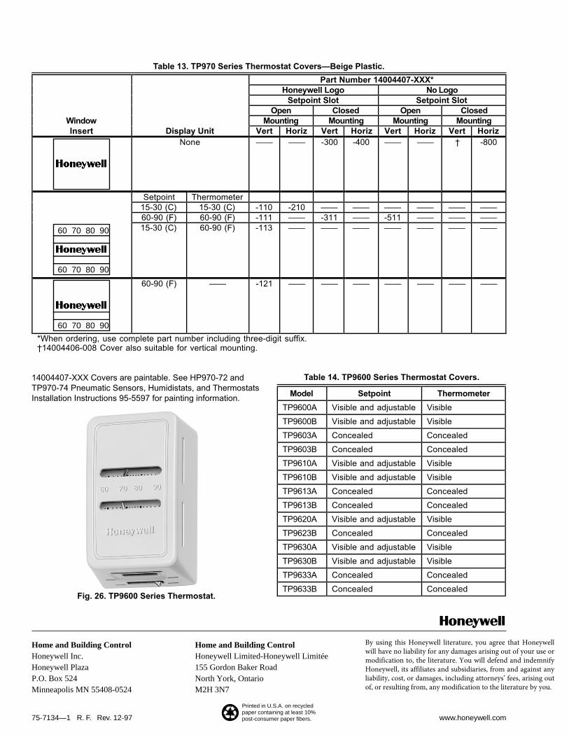
Model Setpoint Thermometer
TP9600A Visible and adjustable Visible
TP9600B Visible and adjustable Visible
TP9603A Concealed Concealed
TP9603B Concealed Concealed
TP9610A Visible and adjustable Visible
TP9610B Visible and adjustable Visible
TP9613A Concealed Concealed
TP9613B Concealed Concealed
TP9620A Visible and adjustable Visible
TP9623B Concealed Concealed
TP9630A Visible and adjustable Visible
TP9630B Visible and adjustable Visible
TP9633A Concealed Concealed
TP9633B Concealed Concealed
Table 13. TP970 Series Thermostat Covers—Beige Plastic.
14004407-XXX Covers are paintable. See HP970-72 andTP970-74 Pneumatic Sensors, Humidistats, and ThermostatsInstallation Instructions 95-5597 for painting information.
Part Number 14004407-XXX*Honeywell Logo No Logo
Setpoint Slot Setpoint SlotOpen Closed Open Closed
Window Mounting Mounting Mounting MountingInsert Display Unit Vert Horiz Vert Horiz Vert Horiz Vert Horiz
None —— —— -300 -400 —— —— † -800
Setpoint Thermometer15-30 (C) 15-30 (C) -110 -210 —— —— —— —— —— ——60-90 (F) 60-90 (F) -111 —— -311 —— -511 —— —— ——15-30 (C) 60-90 (F) -113 —— —— —— —— —— —— ——
60-90 (F) —— -121 —— —— —— —— —— —— ——
*When ordering, use complete part number including three-digit suffix.†14004406-008 Cover also suitable for vertical mounting.
60 70 80 90
60 70 80 90
60 70 80 90
Fig. 26. TP9600 Series Thermostat.
Table 14. TP9600 Series Thermostat Covers.
By using this Honeywell literature, you agree that Honeywell will have no liability for any damages arising out of your use or modification to, the literature. You will defend and indemnify Honeywell, its affiliates and subsidiaries, from and against any liability, cost, or damages, including attorneys’ fees, arising out of, or resulting from, any modification to the literature by you.