Embed Size (px)
Citation preview
5Ghz IEEE 802.11a For Interference Avoidance
TECHNICAL BRIEF

The proliferation of wireless devices in the 2.4GHz ISM (Industrial, Scientific,
and Medical) unlicensed spectrum has created significant sources of
interference for 802.11bg networks. Although sophisticated temporal,
spectral, and spatial interference mitigation techniques are available, the
most common and simplest method for interference mitigation is simple
spectral avoidance; i.e. channel change or band shift.
IEEE 802.11bg networks offer 11 different channels (13 channels for
European ETSI) spaced 5 MHz apart in the 2.4000 to 2.4835 GHz spectrum
(note: transmission signal is 22 MHz therefore adjacent channels are
overlapping).
In cases where a simple channel change is not sufficient to avoid
interference, a band shift from 2.4Ghz (802.11bg) ISM to 5Ghz (802.11a)
UNII (Unlicensed National Information Infrastructure) may be required. If
the network is not designed for dual band 802.11abg operation, then an
upgrade of the clients and/or the infrastructure may be required.
This leads to the question addressed by this paper; “will 5GHz become
equally congested as designers search for “quiet” spectrum?”
Targeted at an electronics retail environment this paper discusses several
consumer electronic interference devices. None the less, much of the
analysis is applicable to generic environments. Finally it is out of the
scope of this paper to discuss the benefits of multi-band networks for
time sensitive multimedia applications (e.g. data/voice/video).
Abstract:
SummaryAlthough the 802.11a 5GHz UNII band is unlicensed; it is the assertion of this paper that interference levels in this band will remain relatively low compared to ISM 2.4GHz for the foreseeable future. Furthermore, 5 GHz offers several sustainable benefits with respect to interference mitigation:
1). Interference Avoidance - 802.11a 5GHz UNII has up to 300MHz of available spectrum for interference avoidance vs. 83MHz in 2.4GHz ISM.
2). Bluetooth & ZigBee (IEEE 802.15.4) Devices - Bluetooth (Instat estimates over 800M devices shipping in 2008) and IEEE 802.15.4 (e.g. ZigBee) operate in the 2.4GHz ISM band. There are no plans to shift to 5GHz.
3). Cordless Phones – Current 5.8 GHz handsets will transition to the recently FCC approved DECT 6.0 Unlicensed Personal Communications Services (UPCS) spectrum at 1.920-1.930 GHz (see cordless phone section below).
4). Wavelength Dependent Applications – Wavelength dependent applications such as microwave ovens and low energy lighting (e.g. 2.45 GHz sulfur lighting magnetrons) will not shift to 5.8 GHz.
5). Physics - Propagation absorption characteristics at 5GHz will curtail widespread wireless appliance migration to this band (especially in residential environments).
6). Connectivity - Reduced antenna apertures at 5GHz decreases connectivity (or increases power required for the same level of connectivity), thereby slowing migration to this band.
7). Coexistence Awareness - wireless development communities are significantly more aware of coexistence and interference issues. Future standards considering the 5.8GHz band will be closely scrutinized.
It is important to note that the shift to 5GHz does have consequences with respect to connectivity (discussed below). In some 802.11 systems this may require the deployment of additional access points and/or alternative antenna technologies.
There can be no guarantee that the 5 GHz UNII band will not become cluttered like 2.4 GHz and shifting to 5GHz is not a replacement for RF spectrum management. However, given the facts cited in this paper, it is our position that the 5 GHz band will offer significant performance benefits with respect to interference over 2.4 GHz for a sustained period of time.
1.0 BackgroundThis paper provides a brief overview of 802.11 interference sources and their respective impact.
Sample sources of interference in the 2.4 GHz ISM band include generic standards based products and specific device types;
2.4 GHz Standards Based Sources of Interferencea) Other 802.11 Co-located nodes (co-channel, adjacent channel)b) Bluetooth Devicesc) IEEE 802.15.4 (ZigBee) Devicesd) WiMax 2.4 Ghze) (Sideband emissions from any transmitter)
3 TECHNICAL BRIEF: 5Ghz IEEE 802.11a For Interference Avoidance
4 TECHNICAL BRIEF: 5Ghz IEEE 802.11a For Interference Avoidance
2.4 GHz Interference Devicesa) Baby monitorsb) Home Video Distributionc) Wireless Speakersd) Cordless Phonese) Commercial & Consumer Microwavesf) Wireless Audio Headsetsg) Low Energy Lighting
The effects and/or signs of interference include;a) Session layer connection Lossb) Excessive 802.11 retries (>10% requires investigation)c) Audio clicks or popsd) Video artifacts (e.g. macro-blocking)e) Increased latencyf) Loss of throughput / system capacity
Interference is a complex multivariate phenomena, but can often be generalized by an overlapping signature in space, time, and frequency. Numerous methods exist to alter one or more of these dimensions in order to improve coexistence. For example:
Frequency Agile SystemsMany RF communications systems are “frequency agile” in that they can be reconfigured to operate on an alternative frequency. In contrast to frequency hop systems, frequency agile systems generally remain on a single channel for sustained period of time.
Frequency Hop Spread Spectrum (FHSS)A form of spread spectrum, FHSS systems distribute energy over the spectrum by hopping across different frequencies during a transmission. As with most spread spectrum systems this makes the system more immune to narrow-band interference.
Adaptive Frequency Hopping (AFH)Used in FHSS (Frequency Hop Spread Spectrum) systems (e.g. Bluetooth), Adaptive Frequency Hopping (AFH) dynamically alters frequency hop sequences to avoid interference.
Adaptive Power Control (APC)Static or dynamic power control is an effective method to control interference. In such cases transmitters radiate the minimum power necessary for effective communications. Brute Force Increase of AP PowerOne method to overcome interference is simply to use higher power (up to regulatory limits). Note however, that this technique often ends in a spiraling of increased power in all devices reverting back to the original problem.
Elimination of Noise SourceUnder some situations it may be possible to locate and isolate and/or “reduce” the noise source(s). Often this is done using a directional antenna and a spectrum analyzer to find and isolate the interference sources.
Antenna DirectivityStatic and dynamic antenna arrays can be used to spatially isolate transmitters/receivers.
Carrier Sense or Clear Channel AssessmentA temporal technique, whereby transmitters inspect the channel and defer a transmission until a clear channel is detected.
5 TECHNICAL BRIEF: 5Ghz IEEE 802.11a For Interference Avoidance
Alternatively, frequency agile systems scan multiple channels to determine the least noisy channel of operation (may be a relatively static process).
Intelligent Adaptive Data Rate ControlsOften algorithms to improve link margins (e.g. using lower data rates) operate well under AWGN channels but poorly under certain interference profiles.
For example a strong Frequency Hop (FH) interferer (e.g. Bluetooth) may cause an 802.11 node to reduce its data rate to improve link margin. Although the link margin increases the amount of time to transmit a packet increases thereby potentially increasing the probability of a BT signal overlapping (jamming) in time. Under such circumstances the 802.11 node must be intelligent enough so as not to lower its data rate.
Code Division / Code DiversityDSSS (Direct Sequence Spread Spectrum) signals can use orthogonal or pseudo-orthogonal codes to allow transmissions to in part overlap in both time and space. Such systems require time coordination. Such wideband spread spectrum signals are less vulnerable to narrow band interferers.
As described, there are numerous techniques and methods to overcome interference many of which are integrated into the waveform and/or protocols (e.g. spread spectrum) and others which can be deployed after the fact (e.g. antenna directivity). An optimum design requires a complex, extensive analysis of the requirements and environment.
1.1 A First Order Assessment of In-band Interference Problem
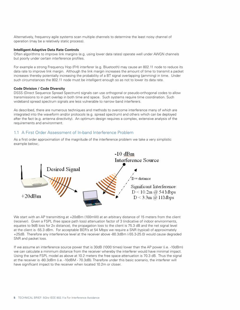
As a first order approximation of the magnitude of the interference problem we take a very simplistic example below;.
We start with an AP transmitting at +20dBm (100mW) at an arbitrary distance of 15 meters from the client (receiver). Given a FSPL (free space path loss) attenuation factor of 3 (indicative of indoor environments, equates to 9dB loss for 2x distance), the propagation loss to the client is 75.3 dB and the net signal level at the client is -55.3 dBm. For acceptable BER’s at 54 Mbps we require a SNR (typical) of approximately +25dB. Therefore any interference level at the receiver above -80.3dBm (-55.3-25.0) would cause degraded SNR and packet loss.
If we assume an interference source power that is 30dB (1000 times) lower than the AP power (i.e. -10dBm) we can calculate a minimum distance from the receiver whereby the interferer would have minimal impact. Using the same FSPL model as above at 10.2 meters the free space attenuation is 70.3 dB. Thus the signal at the receiver is -80.3dBm (i.e. -10dBM - 70.3dB). Therefore under this basic scenario, the interferer will have significant impact to the receiver when located 10.2m or closer.

6 TECHNICAL BRIEF: 5Ghz IEEE 802.11a For Interference Avoidance
In contrast, an 11Mbps transmission requires an SNR of approximately 10 dB and thus the minimum distance from the receiver to the interferer moves from 10.2m to 3.3m.
As illustrated the high SNR’s required for high bit rate (higher order modulation) does increase the system’s susceptibility to interference.
2.0 Why 5GHz Will Remain Less Cluttered Than 2.4GHz2.1 Interference Avoidance - 802.11a UNII has up to 300MHz for Spectral Avoidance (as compared to 100MHz @ ISM)
The simplest method of avoiding interference is to move either the source of the interference or the 802.11 network itself to an alternative frequency. IEEE 802.11a UNII offers 300MHz of available spectrum as opposed to the 100MHz in ISM.
U-NII defines a spectral domain in the 5 GHz region regulated by the FCC. Power limits for U-NII are defined under Part 15 - Radio Frequency Devices, Subpart E - Unlicensed National Information Infrastructure Devices, Paragraph 15.407.
As shown in Table 1 the 802.11a 5.8 GHz UNII spectrum is divided into three domains (all channels shown with center frequency):
Frequency Range
Bandwidth ChannelsFrequency
(MHz)FCC Country
36 5180
40 5200
44 5220
48 5240
52 5260
56 5280
60 5300
64 5320
149 5745
153 5765
157 5785
161 5805
Max Power (mW - dBm)
Max EIRP (mW-)
U-NII Lower Band
5.150 to 5.250 GHz 100 MHz
U-NII Middle Band
5.250 to 5.350 GHz 100 MHz
U-NII Upper Band
5.725 to 5.825 GHz 100 MHz
40 mW 16.0 160mW 22.0FCC
15.247USA
200 mW 23.0 800mW 29.0FCC
15.247USA
800 mW 29.0 1600mW 32.0FCC
15.247USA
Table 1: IEEE 802.11a 5.8GHz UNII Summary
7 TECHNICAL BRIEF: 5Ghz IEEE 802.11a For Interference Avoidance
This creates a total of 12 non-overlapping 802.11a channels. The lower and middle bands can be visualized as a contiguous block. The lowest channel (5180) is spaced 30 MHz from the lower edge of the band. Similarly the upper most channel (5320) is spaced 30 MHz from the upper most edge of the band.
Note that the upper band does not have similar edge guards.
As illustrated above 802.11a UNII encompasses 300 MHz of spectrum. In contrast to 802.11bg:• Operating frequencies: 2.40 - 2.4835 GHz ISM band • Max Transmit Power = +20 dBm (100mW)• Total Band ~ 83 MHz• 802.11b (22MHz per Channel), 802.11g (20 MHz per channel)• 11 Channels in the US space at 5 MHz intervals• 3 Non-Overlapping Channels (1, 6, 11)
A summary of ISM 802.11bg spectrum by channel and region is shown in Table 2.
Center Frequency (MHz) Americas EMEA JAPAN
1 2412 X X X
2 2417 X X X
3 2422 X X X
4 2427 X X X
5 2432 X X X
6 2437 X X X
7 2442 X X X
8 2447 X X X
9 2452 X X X
10 2457 X X X
11 2462 X X X
12 2467 – X X
12 2472 – X X
An issue to consider with band switch is the support for and migration of peripherals (e.g. mobile printers).
Table 2: ISM 802.11BG Summary
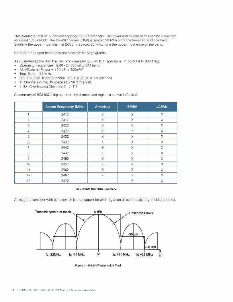
Figure 1: 802.11b Transmission Mask

2.2 Transmitter Side bands & Adjacent Channel Interference
RF transmissions have spectral energy (splatter) outside of the prescribed channel bandwidth which may create interference on adjacent channels. The spectral profile of IEEE 802.11b CCK transmissions are required to be least 30 dB down at +/- 11 MHz from the center frequency (Figure 1) In contrast, 802.11g & 802.11a OFDM transmissions are only 20 dB down at +/- 11 MHz. Therefore, although we define non-overlapping channels using the channel bandwidth prescribed by IEEE definitions, it is important to note that added separation will improve adjacent channel interference.
2.3 US Cordless Phones Transitioning To DECT 1.9GHz
Cordless phones represent a major source of interference in the 900Mhz, 2.4GHz, and 5.8GHz bands. In contrast to data, which can be significantly buffered and held off from transmission until a clear channel is detected, voice or other isochronous traffic applications must transmit in relative real-time (ITU-T G.131 recommends < 150ms max delay). On a positive note voice requires relatively low bandwidth enabling narrow band signaling which is less degrading to wideband spread spectrum waveforms.
In the US the cordless handset market has gone through several frequency shifts. In 2003, cordless phones in the US began transitioning to 5.8 GHz to avoid congested 2.4 GHz band.
In 2005 the FCC approved “DECT 6.0” devices for the US. Touted as “interference free”, DECT 6.0 devices operate at 1.920 to 1.930 GHz (Unlicensed Personal Communications Services (UPCS)).
We believe over time there will be a continual shift to DECT 6.0 (1.9GHz) devices.
Figure 2: IEEE 802.11a Transmission Mask
8 TECHNICAL BRIEF: 5Ghz IEEE 802.11a For Interference Avoidance

9 TECHNICAL BRIEF: 5Ghz IEEE 802.11a For Interference Avoidance
2.4 Wireless Speakers
A number of home theatre systems are now offering wireless speakers (e.g. subwoofers). In most cases these systems these systems are broadcasting at 2.4GHz.
An actual user manual includes the following excerpt on interference:
The manufacturer indicates that the system automatically seeks a clear channel across three available channel selections.
To provide more insight into the wireless technology used in these speaker applications we explored several chipset/module offerings for wireless speakers:
2.4GHz Digital Wireless Audio Transceiver (SOYO-WT24G01).• Application: Home Theater Rear Speakers & General Wireless Speakers• Digital audio with 64K sampling rate and 16-bit resolution.• Operating at 2.4GHz ISM band with 20 selectable channels.• -85dBm receiving sensitivity, 45dB channel rejection and Application distance up to 180 meters (L. O. S. ) with perfect reception.• Modulation GFSK • TX Power (MAX) 20dBm(Can choose from 0dBM till 20dBM)
2.4 GHz Kleer KLR3012• Application: Home Theater Rear Speakers & General Wireless Speakers• 16 Channels• 1.5 dBm Output Power• 3MHz Bandwidth Though not as pervasive several chipsets/modules were found operating at 5.8GHz. For example, the SST MelodyWing SP radio module operates at both 2.4 GHz and 5GHz with a programmable power level of up to 20dBm.

10 TECHNICAL BRIEF: 5Ghz IEEE 802.11a For Interference Avoidance
All the wireless speaker transceiver devices evaluated are frequency agile with 16 to 20 available channels spanning the 2.4GHz ISM band and in the case of SST spanning both 2.4GHz and 5GHz bands. Most notable is the power levels which range from 0 dBm to +20dBm.
In conclusion, at the power levels shown, wireless speakers represent a formidable source of interference. On a positive note they are relatively narrow band and frequency agile, thus potentially enabling them to be repositioned outside of the 802.11bg networks (note: if 3 networks are collocated on channels 1,6,11 then the entire band is filled). In theory up to six, 3MHz bandwidth wireless speaker links (a total of 18MHz) could be deployed and occupy the same bandwidth as one 802.11 network (20 to 22 MHz).
Although we expect wireless speakers to be offered at both 2.4GHz and 5 GHz, the narrowband nature of the signal along with the added spectrum in the 5GHz band will more readily support coexistence with 802.11.
2.5 1+ Billion Bluetooth Devices - Not Likely To Migrate To 5GHz
One of the most significant sources of 2.4 GHz interference is Bluetooth. Instat estimates that nearly 800M Bluetooth enabled devices will ship in 2008 alone.
Bluetooth devices use Frequency Hop Spread Spectrum (FHSS) in the same 2.4-2.4835 GHz frequency range as 802.11 bg networks. In general devices hop across 79, 1Mhz channels.
Bluetooth transmit power is either class 1 (100mW, +20dBm), class 2 (2.5mW +4dBm) or class 3 (1 mW, 0dBm). As shown earlier even a class 3 device represents a significant source of interference to 802.11bg networks.
Adaptive Frequency Hopping (AFH) is an interference mitigation technique required on all Bluetooth 1.2 compliant devices (specification in 2003). AFH dynamically alters frequency hop sequences to avoid interference. Although AFH offers significant benefits it does have limitations with respect to proximity to 802.11 devices and applicability in heavily congested spectrum.
In conclusion, although Bluetooth devices could potentially shift to 5GHz it would have to:a) Deal with the additional attenuation, particularly with the human body (a common usage model for a personal area network)
b) Address compatibility with the significant installed base.
2.6 Wireless USB (WUSB) Overlaps 5GHz, But Not An Issue
Wireless USB is based on the WiMedia Alliance Ultra-Wideband (UWB) PHY operating with a BW of over 500Mhz between 3.1 to 10.6 GHz.
The very high bandwidth/low power spectral density of WUSB will minimize its impact on overlapping 802.11a networks. Furthermore, its ability to operate over such a broad spectrum (3.1GHz to 10.6GHz) will in most instances allows it to avoid 802.11a.
2.7 IEEE 802.15.4 (e.g. ZigBee) Use 2.4 GHz Not 5.8 GHz
ZigBee uses a Direct Sequence Spread Spectrum (DSSS) waveform which can be transmitted at several frequencies including 2.4 GHz ISM, but NOT 5.8 GHz. The max power level for ZigBee is 0 dBm (1 mW).
The physical and MAC layers for ZigBee are defined by the IEEE 802.15.4 Working Group and share many of the same characteristics as the IEEE 802.11b standard. Under 802.15.4 the 2.4-GHz ISM band is divided into sixteen channels; each channel occupies 3 MHz and centered at 5 MHz intervals. ZigBee implements a clear channel assessment before transmitting.

11 TECHNICAL BRIEF: 5Ghz IEEE 802.11a For Interference Avoidance
2.8 Reduced Effective Aperture @ 5GHz = Reduce Connectivity = Reduce Migration
Antenna aperture characteristics at 5.25 GHz (vs. 2.54 GHz) are likely to slow the migration of generic wireless appliances to the5 GHz UNII band. An ideal isotropic antenna at 5.8 GHz captures less energy than at 2.4 GHz, therefore, a device moving to 5.8 GHz will have less range (all other factors remaining constant).
Generally this is shown when calculating the received power: Receiver power is frequently estimated for free space loss as: Pr = Receive Power
Pt = Transmit Power Gt = Transmit Antenna Gain Gr= Receive Antenna Gain Lamda = wavelength d= distance between receiver and transmitter n = FSPL factor
This equation incorporates the antenna effective aperture, which is a function of wavelength (frequency):
From these equations, it can be shown that shorter wavelength 5.24 GHz links require approximately 6.8 dB (4 times the power) to achieve the same link performance as a comparable 2.4Ghz link.
2.9 Added Attenuation of Objects @ 5GHz Will Slow Migration
From an RF propagation perspective, objects are measured in terms of wavelengths. The wavelength (wavelength = speed of light / frequency) for 5.8 GHz is ½ that of waves at 2.4 GHz. This difference impacts the way waves propagate around and through objects.
Indoor RF communications is rarely direct line of sight, instead transmissions must radiate through walls and diffract around obstructions. At higher frequencies objects and walls appear thicker as a percentage of the wavelength.
The table below [2] the difference in attenuation between 2.4 GHz and 5GHz signals.
2.4 GHz 5 GHz Interior Drywall 3-4 3-5Cubicel wall 2-5 4-9Wood Door (Hollow-Solid) 3-4 6-7Brick/Concrete wall 6-18 10-30Glass/Window (not tinted) 2-3 6-8Double-pane coated glass 13 20Bullet-proof glass 10 20Steel/Fire exit door 13-19 25-32
As shown 5GHz signals are attenuated by physical obstructions significantly more than 2.4 GHz. It is also important to note that attenuation from a human body is 2-3 dB more at 5GHz than at 2.4 GHz. This makes it even less likely that devices such as Bluetooth will migrate to 5 GHz (Bluetooth device are often worn on the body).
2.10 IEEE802.11n (“11n”)
11n incorporates a number of physical and link layer techniques to achieve improved connectivity and significantly higher data rates (max peak rates up to 600 Mbps). 11n supports either 2.4 GHz or 5 GHz bands and provides for interoperability with legacy 802.11ABG clients (albeit with a degradation in system capacity).
From an interference perspective, 11n is susceptible to the interference sources described in this paper. However, to take full advantage of 11n capacity requires 40Mhz of channel bandwidth. The increased bandwidth further diminishes available spectrum for interference avoidance, increases co-channel and adjacent channel interference, and potentially increases interference susceptibility. These issues are compounded by the limited 2.4 GHz ISM spectrum. Therefore although initial 11n residential systems may be targeted at 2.4 GHz for legacy interoperability, enterprise systems are likely to deploy 11n at 5 GHz for the added spectrum.
On a positive note, 11n does have provisions for directional beam-forming (TxBF) which as mentioned earlier such directionality can reduce interference susceptibility. Furthermore 11n spatial and temporal diversity can reduce susceptibility to some noise sources.
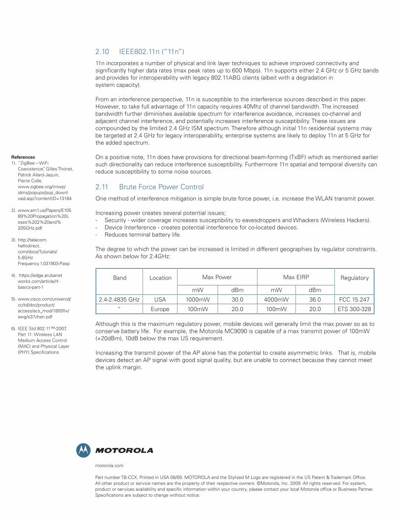
2.11 Brute Force Power Control
One method of interference mitigation is simple brute force power, i.e. increase the WLAN transmit power.
Increasing power creates several potential issues;- Security - wider coverage increases susceptibility to eavesdroppers and Whackers (Wireless Hackers).- Device Interference - creates potential interference for co-located devices.- Reduces terminal battery life.
The degree to which the power can be increased is limited in different geographies by regulator constraints. As shown below for 2.4GHz:
mW dBm mW dBm
2.4-2.4835 GHz USA 1000mW 30.0 4000mW 36.0 FCC 15.247
“ Europe 100mW 20.0 100mW 20.0 ETS 300-328
Although this is the maximum regulatory power, mobile devices will generally limit the max power so as to conserve battery life. For example, the Motorola MC9090 is capable of a max transmit power of 100mW (+20dBm), 10dB below the max US requirement.
Increasing the transmit power of the AP alone has the potential to create asymmetric links. That is, mobile devices detect an AP signal with good signal quality, but are unable to connect because they cannot meet the uplink margin.
motorola.com
Part number TB-CCX. Printed in USA 08/09. MOTOROLA and the Stylized M Logo are registered in the US Patent & Trademark Office. All other product or service names are the property of their respective owners. ©Motorola, Inc. 2009. All rights reserved. For system, product or services availability and specific information within your country, please contact your local Motorola office or Business Partner. Specifications are subject to change without notice.
Max Power Max EIRP RegulatoryLocationBand
References1). “ZigBee – WiFi Coexistence”, Gilles Thonet, Patrick Allard-Jaquin, Pierre Colle, www.zigbee.org/imwp/ idms/popups/pop_downl oad.asp?contentID=13184
2). www.am1.us/Papers/E105 89%20Propagation%20L sses%202%20and% 205GHz.pdf
3). http://telecom. hellodirect. com/docs/Tutorials/ 5.8GHz Frequency.1.031903-P.asp
4). https://edge.arubanet works.com/article/rf- basics-part-1
5). www.cisco.com/univercd/ cc/td/doc/product/ access/acs_mod/1800fix/ awg/s37chan.pdf
6). IEEE Std 802.11™-2007, Part 11: Wireless LAN Medium Access Control (MAC) and Physical Layer (PHY) Specifications