Embed Size (px)
Citation preview
-Pasternack does not make
any representation or warranty regarding the suitability of the part described herein for any particular purpose, and Pasternack does not assume any liability arising out of the use of any part or documentation.
1
TECHNICAL DATA SHEET
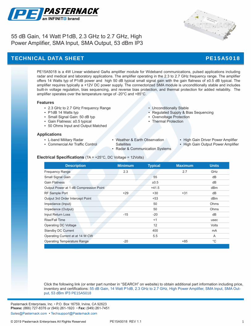
PE15A5018 is a 4W Linear wideband GaAs amplifier module for Wideband communications, pulsed applications including radar and medical and laboratory applications. The amplifier operating in the 2.3 to 2.7 GHz frequency range. The amplifier offers 14 Watts typ of P1dB power and high 50 dB typical small signal gain with the gain flatness of ±0.5 dB typical. The amplifier requires typically a +12V DC power supply. The connectorized SMA module is unconditionally stable and includes built-in voltage regulation, bias sequencing, and reverse bias protection, and thermal protection for added reliability. The amplifier operates over the temperature range of -20°C and +85°C.
Features• 2.3 GHz to 2.7 GHz Frequency Range• P1dB 14 Watts typ• Small Signal Gain: 50 dB typ• Gain Flatness: ±0.5 typical• 50 Ohms Input and Output Matched
• Unconditionally Stable• Regulated Supply & Bias Sequencing• Overvoltage Protection• Thermal Protection
Applications• L-band Military Radar• Commercial Air Traffic Control
• Weather & Earth Observation Satellites
• Radar & Communication Systems
• High Gain Driver Power Amplifier• High Gain Output Power Amplifier
Electrical Specifications (TA = +25°C, DC Voltage = 12Volts)
Description Minimum Typical Maximum Units Frequency Range 2.3 2.7 GHz Small Signal Gain 55 dB Gain Flatness ±0.5 dB Output Power at 1 dB Compression Point +41.5 dBm RF Sample Port +29 +30 +31 dB Output 3rd Order Intercept Point +53 dBm Impedance (Input) 50 Ohms Impedance (Output) 50 Ohms Input Return Loss -15 -20 dB Rise/Fall Time <1 usec Operating DC Voltage 12 Volts Standby DC Current 400 mA Operating Current at at 14 W CW 5.5 A Operating Temperature Range -20 +85 °C
.
Click the following link (or enter part number in “SEARCH” on website) to obtain additional part information including price, inventory and certifications: 55 dB Gain, 14 Watt P1dB, 2.3 GHz to 2.7 GHz, High Power Amplifier, SMA Input, SMA Out-put, 53 dBm IP3 PE15A5018
PE15A5018
PE15A5018 REV 1.1
55 dB Gain, 14 Watt P1dB, 2.3 GHz to 2.7 GHz, High Power Amplifier, SMA Input, SMA Output, 53 dBm IP3

-Pasternack does not make
any representation or warranty regarding the suitability of the part described herein for any particular purpose, and Pasternack does not assume any liability arising out of the use of any part or documentation.
2
TECHNICAL DATA SHEET
Protections
3. Current may be drawn if the +VDC is tied to chassis ground. Current will not go through the unit.
Description ValueMax RF Input +10 dBmLoad VSWR @ 20 Watts ∞ at all amplitudes / phase angles
Thermal Shutdown Unit will shut down if case temperature exceeds +85o C, will automatically turnback on when case temperature falls ~ 10o C from shutdown.
Over Voltage Unit will shut down if input voltage exceeds +14 VDC
Under Voltage Unit requires a minimum of +9 VDC to enable. Unit will also shut down if VDC falls below +9 V during operation.
True Reverse Unit will not enable and the unit will not draw current if +VDC and Ground are reversed3
Mechanical SpecificationsSizeLength 6 in [152.4 mm]Width 3.5 in [88.9 mm]Height 0.69 in [17.53 mm].
Weight 0.948 lbs [430.01 g]Input Connector SMA FemaleOutput Connector SMA FemaleCooling Requires heatsink, use PE15C5013 or PE15C5013F
Environmental SpecificationsTemperatureOperating Range -20 to +85 deg CStorage Range -55 to +100 deg C..
Humidity 95Shock MIL-STD-810F Method 516.5Vibration MIL-STD-810F Method 516.5
PE15A5018
PE15A5018 REV 1.1
Click the following link (or enter part number in “SEARCH” on website) to obtain additional part information including price, inventory and certifications: 55 dB Gain, 14 Watt P1dB, 2.3 GHz to 2.7 GHz, High Power Amplifier, SMA Input, SMA Out-put, 53 dBm IP3 PE15A5018
55 dB Gain, 14 Watt P1dB, 2.3 GHz to 2.7 GHz, High Power Amplifier, SMA Input, SMA Output, 53 dBm IP3

-Pasternack does not make
any representation or warranty regarding the suitability of the part described herein for any particular purpose, and Pasternack does not assume any liability arising out of the use of any part or documentation.
3
TECHNICAL DATA SHEET
Compliance Certifications (see product page for current document)
Plotted and Other DataNotes: • Values at +25 °C, sea level• ESD Sensitive Material, Transport material in Approved ESD bags. Handle only in approved ESD Workstation.• Heat Sink Required for Proper Operation, Unit is cooled by conduction to heat sink.
PE15A5018
PE15A5018 REV 1.1
Click the following link (or enter part number in “SEARCH” on website) to obtain additional part information including price, inventory and certifications: 55 dB Gain, 14 Watt P1dB, 2.3 GHz to 2.7 GHz, High Power Amplifier, SMA Input, SMA Out-put, 53 dBm IP3 PE15A5018
55 dB Gain, 14 Watt P1dB, 2.3 GHz to 2.7 GHz, High Power Amplifier, SMA Input, SMA Output, 53 dBm IP3

-Pasternack does not make
any representation or warranty regarding the suitability of the part described herein for any particular purpose, and Pasternack does not assume any liability arising out of the use of any part or documentation.
4
TECHNICAL DATA SHEET PE15A5018
PE15A5018 REV 1.1
Click the following link (or enter part number in “SEARCH” on website) to obtain additional part information including price, inventory and certifications: 55 dB Gain, 14 Watt P1dB, 2.3 GHz to 2.7 GHz, High Power Amplifier, SMA Input, SMA Out-put, 53 dBm IP3 PE15A5018
Amplifier Power-up Precautions 1.) Confirm that proper ESD precautions and controls are always in place before handling any Amplifier module.
2.) Confirm adequate thermal management is in place to effectively dissipate heat away from the Amplifier package. The Amplifier operational
baseplate temperature must be within the operational temperature range stated in the Amplifier datasheet. Depending on the design and thermal requirements, using a heatsink with cooling fan is always recommended for safe reliable operation. A heat sink without a cooling fan may also be used. Damage caused from overheating will void the warranty.
3.) Confirm adequate system grounding is established. The DC power supply and Amplifier must have a common ground in order to operate properly.
4.) Power Amplifiers may require additional DC Current when initially powered-up. Depending on the design, the input current draw could range from an additional 10% to 100% above the maximum rated DC current of the Amplifier. This varies based on product part number.
5.) Confirm the DC power supply, if limited, is set to allow for additional start-up current that’s rated for the Power Amplifier.
6.) Confirm the system is designed and calibrated for 50 ohms. Any impedance mismatch may cause performance issues.
7.) Preform a CALIBRATION (if required) with the loads before connecting the Amplifier to the Network Analyzer to ensure proper performance. 8.) Use a fixed attenuator between the signal source and input port of the Amplifier to optimize the input VSWR match.
9.) Confirm the input power level at the input port of the amplifier does not exceed the maximum rated limit for input power (as stated in the
Amplifier datasheet). Pin for Small Signal Gain = P1dB-SSG-10 dB Pin for P1dB = P1dB-SSG+1 dB
10.) Confirm the Network Analyzer is always connected to the Amplifier first before DC power is applied to the Amplifier.
11.) As long as the input and output ports of the amplifier are connected to a 50Ohm load and RF signal power is applied, the Amplifier can be powered up with DC voltage.
12.) Confirm the Amplifier output load is matched for a 50 Ohm impedance and will not exceed the maximum rated VSWR or Return Loss limit
for the Amplifier. Exceeding the maximum rated VSWR or Return Loss limit will result in reflected signal power that could damage the Amplifier and void the warranty.
13.) Power Amplifier connected to an Antenna for signal transmission - It’s strongly recommended to use a high power fixed attenuator pad or an Isolator between the output port of the Amplifier and input port to the antenna. Any reflected signal power due to impedance mismatch will likely damage the Amplifier and void the warranty.
14.) The attenuator or isolator used at the output port of the Amplifier must be rated to handle the output power level and operational frequency band of the amplifier.
55 dB Gain, 14 Watt P1dB, 2.3 GHz to 2.7 GHz, High Power Amplifier, SMA Input, SMA Output, 53 dBm IP3

-Pasternack does not make
any representation or warranty regarding the suitability of the part described herein for any particular purpose, and Pasternack does not assume any liability arising out of the use of any part or documentation.
5
TECHNICAL DATA SHEET PE15A5018
PE15A5018 REV 1.1
Typical Performance Data
dB
dBm
-40-30-20-10
010203040506070
Freq.(MHz)
Gain and Input Return Loss
Gain(dB) 25 C
IN_Return Loss(dB)
121518212427303336394245
Freq.(MHz)
P1dB and Psat
P1dB (dBm)
Psat (dBm)
Click the following link (or enter part number in “SEARCH” on website) to obtain additional part information including price, inventory and certifications: 55 dB Gain, 14 Watt P1dB, 2.3 GHz to 2.7 GHz, High Power Amplifier, SMA Input, SMA Out-put, 53 dBm IP3 PE15A5018
55 dB Gain, 14 Watt P1dB, 2.3 GHz to 2.7 GHz, High Power Amplifier, SMA Input, SMA Output, 53 dBm IP3
-Pasternack does not make
any representation or warranty regarding the suitability of the part described herein for any particular purpose, and Pasternack does not assume any liability arising out of the use of any part or documentation.
6
TECHNICAL DATA SHEET
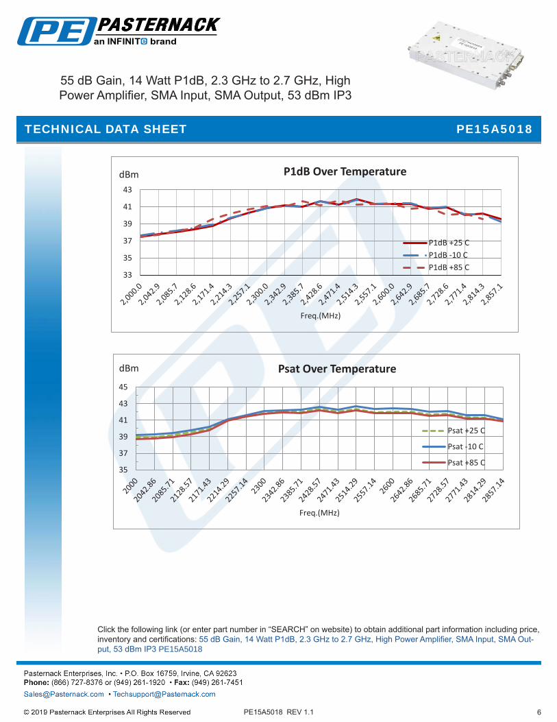
dBm
dBm
33
35
37
39
41
43
Freq.(MHz)
P1dB Over Temperature
P1dB +25 CP1dB -10 CP1dB +85 C
35
37
39
41
43
45
Freq.(MHz)
Psat Over Temperature
Psat +25 C
Psat -10 C
Psat +85 C
Click the following link (or enter part number in “SEARCH” on website) to obtain additional part information including price, inventory and certifications: 55 dB Gain, 14 Watt P1dB, 2.3 GHz to 2.7 GHz, High Power Amplifier, SMA Input, SMA Out-put, 53 dBm IP3 PE15A5018
PE15A5018
PE15A5018 REV 1.1
55 dB Gain, 14 Watt P1dB, 2.3 GHz to 2.7 GHz, High Power Amplifier, SMA Input, SMA Output, 53 dBm IP3
-Pasternack does not make
any representation or warranty regarding the suitability of the part described herein for any particular purpose, and Pasternack does not assume any liability arising out of the use of any part or documentation.
7
TECHNICAL DATA SHEET
55 dB Gain, 14 Watt P1dB, 2.3 GHz to 2.7 GHz, High Power Amplifier, SMA Input, SMA Output, 53 dBm IP3 from Pasternack Enterprises has same day shipment for domestic and International orders. Our RF, microwave and millimeter wave products maintain a 99.4% availability and are part of the broadest selection in the industry.
Click the following link (or enter part number in “SEARCH” on website) to obtain additional part information including price, inventory and certifications: 55 dB Gain, 14 Watt P1dB, 2.3 GHz to 2.7 GHz, High Power Amplifier, SMA Input, SMA Output, 53 dBm IP3 PE15A5018
URL: https://www.pasternack.com/50-db-gain-2.7-ghz-high-power-high-gain-amplifier-sma-pe15a5018-p.aspx
PE15A5018
PE15A5018 REV 1.1
55 dB Gain, 14 Watt P1dB, 2.3 GHz to 2.7 GHz, High Power Amplifier, SMA Input, SMA Output, 53 dBm IP3
-Pasternack does not make
any representation or warranty regarding the suitability of the part described herein for any particular purpose, and Pasternack does not assume any liability arising out of the use of any part or documentation.
8PE15A5018 REV 1.1
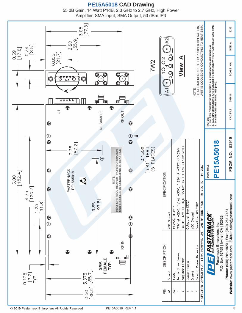
55 dB Gain, 14 Watt P1dB, 2.3 GHz to 2.7 GHz, High Power Amplifier, SMA Input, SMA Output, 53 dBm IP3
PE15A5018 CAD Drawing