Embed Size (px)
Citation preview

5 1111/ii iVews SEPTEMBER-OCTOBER, 1951 VOL. 6-NO. 5
6- ETER RECEIVER Economical Six -tube Superhet for DX, Mobile or CD Use
s
._: . ,, ;'a;°,». ,. .y i. °
b ss - r . .. da
si , °
,rr` `)gi t3"Ir 4°-,. `o [ j:::a
u [1.. ° . + o
I Fig. 1. Front panel view of six -meter receiver. Controls in bottom row, left to right, are audio gain, headphone jack, AVC switch and r -f gain. The BFO control and switch are at upper left, and ANL control and switch at upper right.
A receiver designed and built for a single amateur band may seem like a luxury to many amateurs, but this is not the case when the high -frequency bands are considered. Band -switching can be accomplished on frequencies between 50 and 150 megacycles. In fact, many commercial band -switching receivers now in- clude the six -meter band. However, inclusion of more than one band on any receiver means that the design is a compromise, and the higher the frequency con- sidered, the greater the compromise.
This does not mean that it is simple to design a one - band receiver, but it does mean that the designer can devote his efforts to producing a receiver which has maximum performance over a narrow range of fre- quencies. Usually this means a superior receiver and, strangely enough, a simpler receiver.
This six -meter receiver about to be described is
C/NlielliJ'
simple, has low current drain, and yet has a noise figure of between 5 and 7 db. Most important of all, it is not difficult to build. The average amateur should have no trouble putting it together and making it work properly.
DESIGN CONSIDERATIONS Basically, the idea was to get a six -meter receiver
that was sensitive enough to do serious DX work, and yet be simple to build and low in cost. Because this receiver might be used for civil -defense work or mobile work, power -supply drain became a consideration.
Six miniature tubes are used, two of them twin - triodes and one a twin -diode. This gives the receiver the equivalent of nine tubes. All of the popular super - het functions are included: AVC, BFO and noise limiter. In order to keep the design simple, no trick
i

6 -METER RECEIVER
circuits are employed. Sensitivity is achieved by the proper choice of the input circuit and r -f amplifier tube.
The idea of double -conversion, that is, the use of two different I -F frequencies, was discarded because it would add to the complexity of the receiver. The receiver as designed could use more selectivity-most receivers can-but until the six -meter band becomes more heavily populated, the selectivity achieved in this receiver is adequate.
In order to keep the six -meter receiver independent of the a -c line, the power supply has been eliminated. For home use a separate a -c power supply can be em- ployed, and for mobile or civilian -defense use a vibrator power supply is adequate. The voltage re- quired is not critical (225 to 300 volts) and the current drain is low (50 to 65 mils).
MOBILE AND CD ASPECT
It might seem strange to say that a receiver which is housed in a 10 by 7 by 8 inch cabinet is suitable for mobile work, but such is the case. Recent trends in mobile and emergency work have been to keep the transmitting and receiving equipment as an integral unit, yet one which is not mounted in any particular car.
This system has several advantages. For example, assume that the receiver, transmitter and vibrator power supply are mounted on a piece of wood which will fit comfortably on the front seat beside the driver. Two clip leads can be used for the battery connection, or a special lead can be used which will plug into the cigarette lighter socket. All that is needed now is an antenna (assuming a relay is used to switch the antenna from transmitter to receiver).
The antenna may be mounted on the car, or the
Electrical Circuit
CI
ANT 1
6AK5 z12AT7
5
C3 R6
212AT7 6
OSC. C31 i C
I
c ^ L3 O(
/R3030
1029 T BFO %
6AK5 12AT7
antenna may be mounted on an insulating board which fits or clamps over the glass on one of the car windows. In the latter case, the entire station is com- pletely independent of the automobile.
Only an independent station installation of this sort can be considered to be a true emergency station. Any car which is available serves as the home for a station of this sort. Any six -volt car battery serves as a prime source of power. Thus the station can be used in an attic, in a medical center, or even in the top of a tree. A mobile rig mounted in a car can only go where a car can go, while an independent station can go anywhere that human hands can carry it.
CIRCUIT DETAILS
Refer to the circuit diagram, Fig. 2. The 6AK5 miniature tube serves as a pentode r -f amplifier. The input circuit is broad -band; that is, when L1 is cor- rectly tuned, the r -f stage will operate properly over the range 50-54 megacycles. In order to maintain a low noise figure and broad -band characteristics, it is vital that the proper antenna be used. For the con- stants shown a 50 ohm antenna is correct. A 75 ohm antenna can also be used if some change in the band- pass characteristics can be tolerated.
The 6AK5 tube feeds a 12AT7, one half of which serves as the local oscillator, and the other half acting as the mixer. Both the oscillator and mixer have tuned circuits, with C6A tuning the mixer grid and C6B tuning the oscillator grid. The oscillator section is a Colpitts oscillator. This type of circuit is used so that a coil tap is not required. The r -f choke required in the cathode circuit is relatively simple to provide at this frequency. The oscillator is designed to work on the high side of the received signal, for reasons which will be discussed subsequently.
68J6
BWE GREEN BWE
124X7
-6BJ6
6AL5 12A%7%7 6AK6
al )4 31 ( Y -'¡'a-'6 3+4 X 1 x x #
6AL5
GREEN
F P 6; 250 - AC. OR 300V.
DC.
Fig. 2. Circuit diagram of six -meter receiver
2
Rle
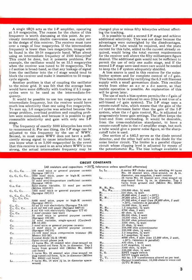
A single 6BJ6 acts as the I -F amplifier, operating at 5.0 megacycles. The reason for the choice of this frequency is worth discussing at this point. As pre- viously mentioned, double conversion was ruled out in the design of this receiver. The receiver must tune over a range of four megacycles. If the intermediate frequency is lower than two megacycles, images will be found in the 50-54 megacycle band. What about using an intermediate frequency of 2500 kilocycles? This could be done, but it presents problems. For example, the oscillator would be on 52.5 megacycles when the receiver was tuned to 50 megacycles. The r -f section is broad -band, so that any leakage of signal from the oscillator into the r -f stage would tend to block the receiver and make it insensitive to 50 mega- cycle signals.
Another problem is that of coupling the oscillator to the mixer grid. It was felt that the average ham would have some difficulty with tracking if 2.5 mega- cycles were to be used as the intermediate -fre- quency.
It would be possible to use ten megacycles as an intermediate frequency, but the receiver would have much less selectivity than one using five megacycles. To sum up, 5.0 megacycles was selected because the image problem, overload problem and coupling prob- lem were minimized, and because it is possible to get reasonable selectivity and gain with only one I -F stage.
The frequency of exactly 5000 kilocycles has much to recommend it. For one thing, the I -F stage can be adjusted to this frequency by the use of WWV. Second, in most cases WWV does not have a suffi- ciently strong signal to cause interference. At least, you know what is on 5.000 megacycles! In the event that this receiver is used in an area where WWV is too strong, the actual intermediate frequency may be
CI, Cn, C2e
changed plus or minus fifty kilocycles without affect- ing the tracking.
It is possible to add a second I -F stage and achieve additional selectivity. This was not done because the advantages were outweighed by the disadvantages. Another I -F tube would be required, and the plate current for this tube, added to the current already re- quired, would bring the total current requirements for the receiver well above the fifty milliampere figure desired. The additional gain would not be sufficient to permit the use of only one audio stage, and if the second I -F stage were used more care would be needed to keep the I -F system adequately shielded.
A bias source is used in this receiver for the noise - limiter system and for complete control of r -f gain. This bias is obtained by rectifying the 6.3 volt filament supply with a small germanium diode. This rectifier works from either an a -c or a d -c source, so that mobile operation is possible. An explanation of this will be given later.
The use of such a bias system permits the r -f gain of the receiver to be reduced to zero (this is not true of a self -biased r -f gain system). The I -F stage uses a remote -cutoff tube, which means that the gain of the r -f system decreases faster than the gain of the I -F system, when the r -f gain control, R17, is adjusted to progressively lower gain settings. The effect keeps the front-end from overloading. It would be desirable, from the cross -modulation standpoint, tc have a remote -cutoff tube in the r -f amplifier stage, but such a tube would give a poorer noise figure, so the sharp - cutoff tube is used.
One section of a 6AL5 serves as the diode second detector, and the other half acts as the diode for the noise limiter circuit. The limiter is a parallel clipper circuit whose clipping level is adjusted by means of the potentiometer R14. The bias voltage available is
CIRCUIT CONSTANTS
(All resistors and capacitors t20% tolerance unless specified otherwise) 100 mmf mica or general purpose ceramic (Sprague 19C11)
C2, Ca, Co, C12 .1000 mmf mica, paper or high -K ceramic (Sprague 19C1)
C. 10 mmf zero -temperature coefficient ceramic (Sprague 19C3) Split -stator variable, 12 mmf per section (Millen 23912C) 1000 mmf mica or general purpose ceramic (Sprague 29C21)
C9, C 0, Cu, Cla, CI6, Cu, Csa, Ca
C,A, COB
Cr, C,, C^,
5000 mmf mica, paper or high -K ceramic (Sprague 29C1)
C,,, Cu 50 mf 25 volt electrolytic (Sprague TA -50) CI,, COI, C22 0 05 mf 400 volt paper (Sprague 68P10)
8 mf 450 volt electrolytic (Sprague UT -8) 2 mmf ceramic (see text) 50 mmf mica or general purpose ceramic (Sprague 19C28)
C21 10 mmf variable, single-spaced (Cardwell ZR-10-AS) 5 mmf mica or general purpose ceramic 10 mmf mica or general purpose ceramic (Sprague 19C19) 15-120 mmf mica compression trimmer (El Menco 302-M) Crystal diode (G -E 1N48) Open -circuit phone jack 12 turns No. 26 enamel wire close -wound on slug -tuned coil form )4 in. in diameter. Tap 2
turns from ground end (Millen No. 69042 coil form)
Ls 5 turns No. 26 enamel wire close -wound on slug -tuned coil form, V. in. in diameter (Millen No. 69042 coil form)
La 4 turns No. 14 wire Mj in. in diameter space - wound
C19 C29
Cu
Cao Cal
Cos
D J Li
L4, L, 6 -meter RF choke made by winding 44 turns No. 30 enamel wire, close -wound, on {r in. diameter, one megohm, 2 -watt resistor
Li 36 turns No. 36 enamel wire close -wound on slug -tuned form 3á in. in diameter. Tap 9 turns from ground end (Millen No. 69042 coil form)
RI, R9, Rn, Rea, R. 100,000 ohm, 3,1 watt
Rs 220 ohm, M watt R3 39,000 ohm, 1 watt (.10%) R,, R12 39,000 ohm, 2 watt (10%) Rs 19,500 ohm, 4 watt (two 39 000 ohm, 2 watt
.10%, resistors in parallel) R6 10,000 ohm, 3 watt R,, R01 1 0 megohm, M watt Rs, Rr, 4700 ohm, 2 watt Rio 68 ohm, M watt Ru 68,000 ohm, 2 watt R,t 10,000 ohm, 2 watt Ru 20,000 ohm potentiometer R,s 2200 ohm, 3 watt R,6 22 ohm, M. watt RI7, RI! 250,000 ohm potentiometer Rib 220,000 ohm, M watt. R,9 2 2 megohm, M watt Reo 4 7 megohm, M watt Rn 6000 ohm, 4 watt (two 12,000 ohm, 2 watt,
.10%, resistors in parallel) Rsa 470 ohm, 1 watt R24 0 47 megohm, 3,1 watt Ra 3300 ohm, M watt R0, 330,000 ohm, M watt Si, S, SPST toggle switch S2 SPDT toggle switch Ti, T2 465 kc. I -F transformers altered as per text Ta Output transformer, 10,000 ohms to voice coil
(UTC R -38A)
3

41111~1~2
l
ü, . 4_1,
t. ad
r1;o9
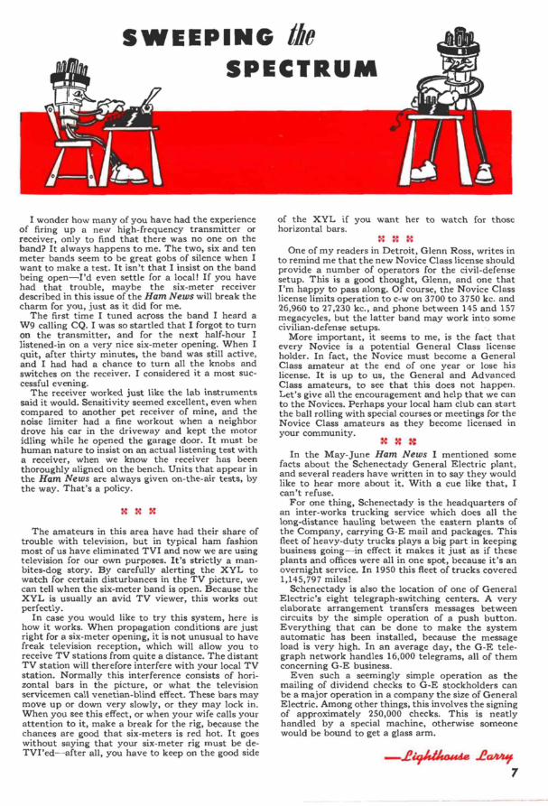
Fig. 3. Underchassis view of six -meter receiver
111 . a. F.
_J
O\
i..%z
W W 3111: I
: 0 1 © '" 4
Fig. 4. Top view of six -meter receiver
Fig. 5. Side view of six -meter receiver
more than sufficient to provide a complete range of clipping level. Use of the noise limiter will be discussed later.
When the arm of S, is connected to Rig, the r -f gain control is in use, and when the arm of S2 is connected to R20 the AVC system is in action. The noise limiter is turned on by connecting together pins 1 and 2 of the 6AL5 through S3.
4
One-half of a 12AX7 twin -triode is used in the beat - frequency oscillator circuit. The circuit shown is a Hartley oscillator. A Colpitts oscillator could have been used, but it seemed easier, at this frequency, to use a tapped -coil Hartley than to provide the cathode choke required for the Colpitts circuit.
The other half of the 12AX7 tube serves in the first audio amplifier stage. This tube was selected because it is a high -gain tube, yet requires only a moderate amount of current. The output stage uses a 6AK6, which provides a watt or so of power for the loud- speaker. A word of precaution about the output stage. If earphones are used, make certain that the loud- speaker is connected to the speaker terminals, or, if you do not wish to use the speaker, connect a ten -ohm two -watt resistor across the speaker terminals. The secondary of the output transformer must always be properly terminated if damage to the transformer is to be avoided.
CONSTRUCTIONAL DETAILS
It is recommended that the mechanical layout shown in the photographs and sketches be followed exactly. A receiver operating on the six -meter band is capable of developing a lot of trouble unless care is taken with parts placement and lead length. The layout shown was used only after a great deal of thought had been put into getting an efficient and well -planned placement of parts.
The cabinet selected for the six -meter receiver is seven inches high, ten inches wide and eight inches deep. The chassis used is a standard seven by nine by two inch chassis. In order to maintain a symmetrical panel layout and yet have correct parts placement, the chassis is attached to the panel so that the top of the chassis is three inches from the top of the panel. This leaves two inches below the bottom of the chassis, on the panel, for the mounting of parts, and places the main tuning dial high enough so that tuning is con- venient.
The exact placement of parts is indicated in the layout sketches and the photographs. Small holes are not indicated on the sketches, but the location of the major components is shown. The position of the main tuning dial is not indicated, because this will depend upon the type of variable condenser used (Ce) and the type of dial used. The dial shown is a Millen No. 10039.
Inasmuch as five -megacycle I -F transformers of the desired type are virtually unobtainable, it is necessary to purchase 465 kilocycle I -F transformers and con- vert them. Practically any low -frequency I -F trans- former is suitable which does not have an iron -core form. Burned -out transformers would be ideal, as long as the mica trimmer condensers in them are in good condition. The transformers used in this receiver are Meissner "Plastic" I -F Transformers. The trans- formers are 1% inches square and 2% inches high and are rated for the frequency range from 400 to 550 kilocycles. Three types are available: input, output and interstage, any of which can be used because you are going to remove the coils anyway. The numbers of these three transformers are: 16- 6658, 16-6659 and 16-6660.
Regardless of the type of transformer you procure, make certain that you do not get an iron -core unit. Further, try to get transformers that have a coil - form % or % inch in diameter. The coil -form in the Meissner transformers just described has a % inch diameter. It is necessary to enlarge this to % inch diameter, but this is easily done by winding the form with paper until it is the right diameter, then putting on a final layer of transparent tape. Now, follow the sketch of the windings shown in Fig. 8, and wind each coil with 40 turns of No. 30 silk or enamel wire. The

spacing between coils is % inch, as shown, and the wire is close -wound. The 40 turns of close -wound No. 30 wire should just take up the % inch winding space shown. For proper connections, follow the color cod- ing shown in the circuit diagram and that shown in Fig. 8. After the coils are wound a small amount of cement may be applied to them to hold the wire in place.
The capacitor which couples the oscillator energy into the mixer, C29, and the capacitor used for BFO injection, C24, are specified as 2 mmf ceramic con- densers. It is possible to use a pair of twisted wires in place of the ceramic condensers. This might even be preferred in the case of C24, because the BFO injection can be varied by means of the twisted -wire condenser until injection is optimum. Some experimentation may be needed on C29 also, although this is not as critical as C24.
The bottom view of the receiver, Fig. 3, shows that shielded wire has been used for the leads that go to the earphone jack and to the audio gain control, Rai. This is advisable in order to prevent feedback between the audio and the I -F portions of the receiver. Shielded wire is also used for the connections to the noise limiter switch, SS, as may be seen in the top view of the receiver, Fig. 4.
If the cabinet used has a solid back it will be neces- sary to drill two clearance holes in this back to pass the coaxial connector and the wire leads going to the terminal board.
TELEVISION STATION IMAGES
'If a television station in your locality operates on channel three, you will receive an image of the sound carrier at 55.75 megacycles, but since this is outside the 6 -meter band, it should not be troublesome. The video carrier, however, which is centered at 61.25 megacycles may cause a troublesome image at 51.25 megacycles. If this is the case, you may wish to install a rejection filter in the receiver antenna circuit. The A.R.R.L. Handbook gives design details on such a filter. It is not advisable to move the oscillator fre- quency below that of the incoming signal, because the tracking of the receiver will be seriously affected. Further, the image problem is probably more serious with the oscillator running in the range 45-49 mega- cycles.
COMPONENT PARTS
Practically none of the parts used in this receiver are critical. Five resistors are specified with a toler- ance of ten percent, but all other parts carry a twenty - percent tolerance. The manufacturer's name and part number are shown in the Circuit Constants list wherever practical. Use of the flat ceramic condensers specified is recommended because they permit you to maintain short lead lengths in the wiring. Further, they take up very little space.
When purchasing these new flat ceramic condensers bear in mind that they come in three general types: 1) those suitable only for bypassing applications (and some coupling applications) where the capacitance stated is a guaranteed minimum value only; 2) those suitable for general purpose use as alternates for foil - mica condensers; and 3) those suitable for use in res- onant or frequency -determining circuits. The informa- tion given under Circuit Constants should enable you to obtain the right condenser for each particular job. The Sprague type numbers given are those of the con- densers actually used in the receiver pictured.
The Millen coil form specified for coils L1, L2 and L5 uses a powdered -iron slug. Brass -slug coil forms can be used, but the coils will probably require a different number of turns if this is done.
10"
SI:J POSITION OF CHASSIS
¿S3
C27ó
- I----^ R14
1é Is"
L@ R 0 -O-' _!'1 R
31 J S
17
-1--
1 B rt l 8
Fig. 6.
-If-I.- lé
Front -panel layout
Fig. 7. Chassis layout
l
Iu
GREEN'
Fig. 8. Detail of I -F coil winding
T I. 4
I,
-1-.,
FINAL ADJUSTMENTS Terminal "B" on the terminal board supplies either
an a -c or a d -c voltage to the bias rectifier. If the receiver is to be used with a -c on the filaments, con- nect a strap from terminal "B" to terminal "F", then connect the 6.3 volts a -c to terminals "F" and "G". If a 6 -volt battery is to be used for the filament source, terminal "B" can stay connected to terminal "F" if the negative of the battery is connected to the junc- tion of terminals "B" and "F", and the positive ter- minal of the battery is connected to terminal "G".
It is essential that a negative d -c voltage be applied to terminal "B" in order that the bias rectifier will pass the direct current and supply bias for the r -f gain control and the noise limiter. If the receiver is used in a car where the negative of the battery is connected to
(Continued on page 8)
5

Receiver Noise Figures
The purpose of this article is to explain in simple language the terms "noise figure" and "signal-to-noise ratio." Admittedly this is not an easy job, but it will be attempted here because so few amateurs have a clear concept of just what noise actu- ally is.
There are four general types of noise, and we are concerned primarily with only one type in this discussion. Static is one type of noise. It is produced primarily by lightning discharges. A second type of noise originates far from our planet Earth, and is called cosmic noise. Third, we have that well-known phenomenon, man-made noise, such as electric razors, which give off a noise similar to a hiss, and we have power leaks and ignition noise which sounds like a series of machine-gun shots. The three types of noise just mentioned are interesting, and they will help us to understand receiver noise problems, but they have absolutely nothing to do with so-called receiver or circuit noise. However, it is this fourth type of noise that we are interested in, because it is the only one we can do anything about.
This type of noise had better be called by another name, which is "thermal" noise. This name describes rather accurately the cause of this type of noise, because it is due to thermal agitation of electrons. That is, in every bit of matter, the electrons are moving back and forth, and this motion causes noise. The only way to stop this noise is to cool the elec- trons down to absolute zero, where they are just too cold to move. Thermal noise, in other words, depends upon the temperature (among other things), and the hotter the electrons, the greater the noise.
What does this mean prac- tically? For one thing, it means that your antenna generates noise, the resistors in the input circuit of your receiver generate noise, and the input tube generates noise, all due to the random motion of the electrons in the antenna wire, the resistor, etc. In fact, prac- tically everything in the receiver generates noise, but generally only the noise in the first stage of the receiver means anything, since noise in subsequent stages is much less than the amplified noise from the first stage.
Thermal noise is random and appears at all frequencies. However, if a receiver is "sharp" there will be less noise in the output, because the receiver is looking at a smaller part of the radio spectrum than a broad receiver, and therefore it is ampli- fying less of the noise. Now that we have some of the funda- mental ideas in mind, let's see what signal-to-noise ratio is.
Let us assume we have a receiver with an antenna connected to it. Present on this antenna will be all four types of noise (static, cosmic, man-made and thermal). Also present on the antenna is a certain signal that we want to receive. Let us as- sume further that the noise (all four types) on the antenna is a certain power, say one microwatt. Let us also assume that the signal has a strength of ten microwatts. The signal-to-noise ratio on the antenna is therefore 10-1. This is a comfortable margin, and you might think that the signal would be easy to receive. It would be, with a good receiver. However, remember that the receiver has its own internal noise. When this signal plus noise gets to the grid of the first tube, there may be enough adjitional noise added by the input circuit that the total noise power is now five microwatts. The signal is still ten micro - watts, but now the signal-to-noise ratio is ten microwatts to five microwatts, or 2-1. You experts may realize that the ex- ample above represents a practically defunct receiver in an even worse location, but the figures do serve to illustrate the problem.
We have had a terrible loss in signal-to-noise ratio, and we barely got the signal into the receiver! Also, from this point on, the receiver can not improve things. The first tube is going to amplify the signal and the noise by the same amount, and
6
Technical
TIDBITS
subsequent stages will do the same, so by having a poor front end on the receiver we have a poor signal-to-noise ratio to work with, and there is nothing we can do about it, except re -design the receiver. It is interesting to note that even if we had noise -free tubes (which we don't), there would still be noise generated by the input circuit (the antenna, lead-in, input impedance, etc.) We can minimize the noise generated in these elements only by careful design.
Let's go back to signal-to-noise ratio again, and assume that the noise on the antenna consists entirely of thermal noise due to the radiation resistance of the antenna. (This means that the antenna is in that perfect receiving location that everyone is looking for but never finding.) We have a certain signal -to - thermal -noise ratio on the antenna, and the ideal receiver would be one which did not change this signal-to-noise ratio. If the receiver adds no noise whatsoever, then the signal-to- noise ratio remains unchanged, and we have what is known as a perfect receiver. The better a receiver you have, the less the signal-to-noise ratio wili be changed, and the worse the receiver, the more the signal-to-noise ratio will be changed. The amount that the receiver changes the signal-to-noise ratio can be ex-
pressed as a figure-in fact, this is called the "noise figure" of a receiver. In other words, the noise figure of a receiver is the measure of how much the signal -to -thermal -noise ratio is decreased due to the receiver itself.
By going into this matter a little more thoroughly, we can see just what this noise figure means expressed in figures. Assume we have some receivers with a bandwidth of 25 kilo- cycles. Let us assume also that we have an antenna with a radiation resistance of 100 ohms, and that this antenna is
at room temperature. (I'm not going to explain this room -tem- perature statement-it is included just to keep this whole thing technically correct.)
The thermal noise power due to this 100 ohm radiation re- sistance is 0.0004 micro-microwatts (this corresponds to a 0.2 microvolt noise voltage). Now we will listen to a signal with a power of 0.002 micro-microwatts (about a 0.5 microvolt signal). The signal-to-noise ratio on the antenna in this case is therefore 0.002 to 0.0004 or 5 to 1. Now, let us connect two hypothetical receivers, having the bandwidth previously mentioned, to this antenna and see what happens. The first receiver is one having a noise figure of 13 db. This might be considered a fair receiver, by the way. What happens to the signal-to-noise ratio with this receiver? Well, 13 db is a power ratio of approximately 20 to 1, so that the noise will be increased 20 times, up to 0.008 micro- microwatts. The signal-to-noise ratio with this receiver will be 0.002 divided by 0.008 or 1 to 4. The noise is four times as strong as the signal. Well, let's try the other receiver.
Assume we have a receiver with a noise figure of 6 db (the six -meter receiver described in this issue of Horn News, for example). Six db is a power ratio of four to one, so now our signal-to-noise ratio will be 0.002 divided by 0.0016, or 1.25 to 1. The signal is louder than the noise, so we stand a good chance of hearing the signal with this receiver.
What are typical noise figures for various types of receivers? This is an interesting question, and you may be surprised at the answer. Very good receivers have noise figures of about 5
to 10 db. Receivers have been built with noise figures as low as a fraction of a db, but these were laboratory receivers-at least, none are available commercially. An average fair super- heterodyne that you might call a communication receiver is liable to have a noise figure as poor as 30 db. Going further, a broadcast -band, table -model, ac -dc set might have a noise figure as high as 50 dbt You pay your money and you take your choice. Of course, you don't need a low -noise receiver for the broadcast band-that's why there are so many fifty kilowatt broadcast stations.
-A9Áthoude .2~1
SWEEPING the
SPECTRUM
1
I wonder how many of you have had the experience of firing up a new high -frequency transmitter or receiver, only to find that there was no one on the band? It always happens to me. The two, six and ten meter bands seem to be great gobs of silence when I want to make a test. It isn't that I insist on the band being open-I'd even settle for a local! If you have had that trouble, maybe the six -meter receiver described in this issue of the Ham News will break the charm for you, just as it did for me.
The first time I tuned across the band I heard a W9 calling CQ. I was so startled that I forgot to turn on the transmitter, and for the next half-hour I listened -in on a very nice six -meter opening. When I quit, after thirty minutes, the band was still active, and I had had a chance to turn all the knobs and switches on the receiver. I considered it a most suc- cessful evening.
The receiver worked just like the lab instruments said it would. Sensitivity seemed excellent, even when compared to another pet receiver of mine, and the noise limiter had a fine workout when a neighbor drove his car in the driveway and kept the motor idling while he opened the garage door. It must be human nature to insist on an actual listening test with a receiver, when we know the receiver has been thoroughly aligned on the bench. Units that appear in the Ham News are always given on -the -air tests, by the way. That's a policy.
The amateurs in this area have had their share of trouble with television, but in typical ham fashion most of us have eliminated TVI and now we are using television for our own purposes. It's strictly a man - bites -dog story. By carefully alerting the XYL to watch for certain disturbances in the TV picture, we can tell when the six -meter band is open. Because the XYL is usually an avid TV viewer, this works out perfectly.
In case you would like to try this system, here is how it works. When propagation conditions are just right for a six -meter opening, it is not unusual to have freak television reception, which will allow you to receive TV stations from quite a distance. The distant TV station will therefore interfere with your local TV station. Normally this interference consists of hori- zontal bars in the picture, or what the television servicemen call venetian -blind effect. These bars may move up or down very slowly, or they may lock in. When you see this effect, or when your wife calls your attention to it, make a break for the rig, because the chances are good that six -meters is red hot. It goes without saying that your six -meter rig must be de- TVI'ed-after all, you have to keep on the good side
of the XYL if you want her to watch for those horizontal bars.
One of my readers in Detroit, Glenn Ross, writes in to remind me that the new Novice Class license should provide a number of operators for the civil -defense setup. This is a good thought, Glenn, and one that I'm happy to pass along. Of course, the Novice Class license limits operation to c -w on 3700 to 3750 kc. and 26,960 to 27,230 kc., and phone between 145 and 157 megacycles, but the latter band may work into some civilian -defense setups.
More important, it seems to me, is the fact that every Novice is a potential General Class license holder. In fact, the Novice must become a General Class amateur at the end of one year or lose his license. It is up to us, the General and Advanced Class amateurs, to see that this does not happen. Let's give all the encouragement and help that we can to the Novices. Perhaps your local ham club can start the ball rolling with special courses or meetings for the Novice Class amateurs as they become licensed in your community.
:4
In the May -June Ham News I mentioned some facts about the Schenectady General Electric plant, and several readers have written in to say they would like to hear more about it. With a cue like that, I can't refuse.
For one thing, Schenectady is the headquarters of an inter -works trucking service which does all the long-distance hauling between the eastern plants of the Company, carrying G -E mail and packages. This fleet of heavy-duty trucks plays a big part in keeping business going-in effect it makes it just as if these plants and offices were all in one spot, because it's an overnight service. In 1950 this fleet of trucks covered 1,145,797 miles!
Schenectady is also the location of one of General Electric's eight telegraph -switching centers. A very elaborate arrangement transfers messages between circuits by the simple operation of a push button. Everything that can be done to make the system automatic has been installed, because the message load is very high. In an average day, the G -E tele- graph network handles 16,000 telegrams, all of them concerning G -E business.
Even such a seemingly simple operation as the mailing of dividend checks to G -E stockholders can be a major operation in a company the size of General Electric. Among other things, this involves the signing of approximately 250,000 checks. This is neatly handled by a special machine, otherwise someone would be bound to get a glass arm.
-2ighthoscde 2aivu j 7
(Continued from page 5) ground, then it will be necessary to use a bias battery in order to obtain bias. In other words, terminal "G" on the receiver is the ground terminal. The receiver ground must be grounded to the automobile ground, which means that in the case stated above, the negative 6 volt supply is at ground potential. The positive 6 volt terminal of the battery can be connected to terminal "F" and still supply filament power, but terminal "B" must be disconnected in this case, otherwise bias voltage would not be developed. However, a small 7.5 volt bias battery can be used, with its negative terminal connected to "B" and its positive terminal to "G." Inasmuch as most cars have the positive side of the battery grounded, it is unlikely that you will encounter the few types of cars with a negative ground system.
To test the receiver, connect either an a -c or a d -c source to terminals "F" and "G" and check to make sure that all fila- ments are lit. Then connect the negative of the high voltage supply to "G" and the positive voltage to "P." Connect a speaker across the "SPKR" terminals, or use a ten -ohm two - watt resistor in place of the speaker. Connect an antenna to the input, and the receiver is ready tc operate.
If you have a grid -dip meter its use is highly recommended. Set Li to 52 megacycles with the grid -dip meter. Set C6 to mid - scale and adjust Cat until the oscillator is operating at 57 mega- cycles, as shown by the grid -dip meter. Now check the fre- quency of L2 and adjust the slug in L2 until it is resonant at 52 megacycles. (All the tubes should be in place when the above adjustments are being made.) If a grid -dip meter is not avail- able, it will he necessary to provide a 52 megacycle signal with a signal generator or with your transmitter, and peak the circuits for the best output when the receiver is operating.
Turn on the receiver, and connect an output meter across the speaker terminals-either a speaker or a load resistor should still be in place. Use the grid -dip meter as a signal source at 52 megacycles, or use some other source of signal, until the output meter shows a deflection. For this test the AVC switch should be in the "off" position. Use the r -f gain control to set the level or the output meter to some convenient point. Also, the noise limiter switch, Si, and the BFO switch, Si, should be in the "off" position. Now, increase the intensity of the r -f signal, either by moving the grid -dip oscillator closer to the receiver, or by advancing the gain on the signal generator, and make certain that the output meter shows an increase in reading when the r -f signal is increased. This is merely to check that the receiver is not overloading. If the output meter does not show an increase in gain, you are using too much r -f signal. In this case, decrease the r -f signal until a slight increase in the r -f signal shows up as a slight increase on the output meter.
Once the above conditions are satisfied, you may align the
l/am IF(1I'S
FROM:
intermediate transformers in a rough manner by adjusting the four trimmers in the I -F transformers for maximum deflection of the output meter. The two I -F transformers will now be operating approximately on the same frequency, so the next step is to set this frequency to 5.0 megacycles. Use a signal gen- erator capable of operation on 5.0 megacycles. You may check its frequency against WWV if you so desire. Connect the out- put of this signal generator to pin 2 of the 12AT7 through a 100 mmf condenser, and advance the control on the signal generator until you get a suitable deflection on the output meter. Now adjust the four trimmers in the two I -F transformers again, in order to get a maximum reading on the output meter. If the output meter tends to go off -scale, reduce the input by the control on the signal generator. The I -F strip should now be aligned.
Next, remove the I -F signal generator and put a signal into the receiver with an r -f signal generator, and if you are using an adjustable condenser of twisted wire for Ca, adjust this until you get a maximum signal in the output meter. This capacitance can be too low or too high, so search for the op- timum point.
The next step is to turn on the BFO and tune the receiver to the frequency of the signal generator, and listen to the beat - note obtained. Adjust Cu, assuming you are using a twisted - wire capacitor, until the beat note is the desired strength. Tune CO, the BFO pitch control, to make certain that you have adequate range. If you do not hear a beat, adjust L; until a beat appears. Tune Ls slowly, as the frequency change is quite rapid when tuning this coil. Obviously, a speaker or earphones must be used for this test. The receiver should now be ready to put on the air.
OPERATING INFORMATION Use a good antenna, and one with the proper impedance.
When properly constructed, this receiver should have a noise figure of about 6 db, which means that it is a very sensitive receiver. As stated before, the I -F bandwidth is not as sharp as some might like it, but it is adequate unless you run into severe QRM conditions. The actual bandwidth will be between 25 and 40 kilocycles, to the half -power point.
The noise limiter is the threshold type, which means it must be adjusted according to the strength of the received signal. If you experience noise, turn on switch S3 and advance Ru until the noise is just equal to the received signal. If the control is advanced further, you will clip the signal as well as the noise. After a little experience you will be able to use the noise limiter control easily, and you will realize the advantage you have in being able to decrease the noise to the point where it is no louder than the received signal.


![RA 5-3300 ]l 7 The Franklin l 5¢ I IVEWS-RECORD I May...r RA 5-3300]l 7" The Franklin l I 5¢ WANT ADS IVEWS-RECORD I Thursd~ VOL. el, NO. 34 MIDDLEBUSH, N. J., TH~IRKDAY, MAy 13j](https://img.dokumen.tips/doc/110x75/5b2eac277f8b9adc6e8c8e34/ra-5-3300-l-7-the-franklin-l-5-i-ivews-record-i-mayr-ra-5-3300l-7-the-franklin.jpg)