Embed Size (px)
DESCRIPTION
Sauer Danfoss
Citation preview
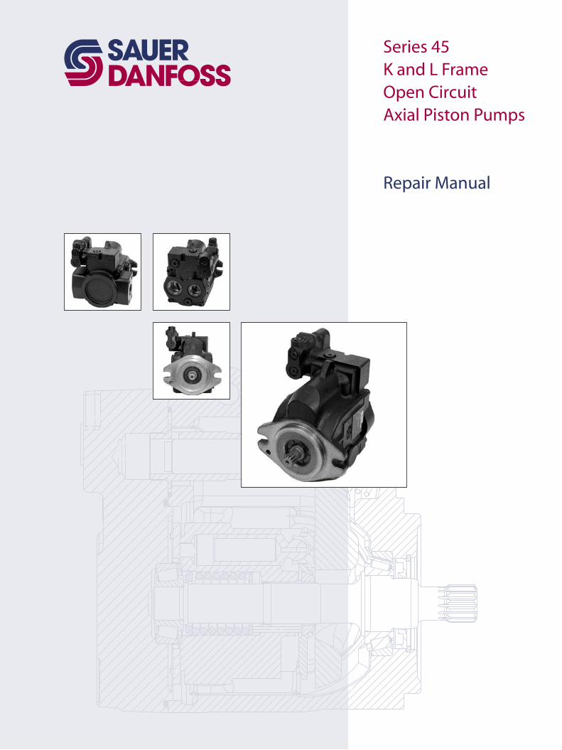
Series 45K and L Frame Open CircuitAxial Piston Pumps
Repair Manual
2 BLN 10196 • 520L0632 • May 2005
Series 45 K and L Frame Open Circuit Axial Piston PumpRepair Manual
© 2005 Sauer-Danfoss. All rights reserved. Printed in U.S.A.
Sauer-Danfoss accepts no responsibility for possible errors in catalogs, brochures and other printed material. Sauer-Danfoss reserves the right to alter its products without prior notice. This also applies to products already ordered provided that such alterations aren’t in conflict with agreed specifications. All trademarks in this material are properties of their respective owners. Sauer-Danfoss and the Sauer-Danfoss logotype are trademarks of the Sauer-Danfoss Group.
Front cover illustrations: F101 472, F101 473, F101 474, F101 475, P104 327
ORGANIZATION AND HEADINGS
To help you quickly find information in this manual, the material is divided into sections, topics, subtopics, and details, with descriptive headings set in red type. Section titles appear at the top of every page in large red type. Topic headings appear in the left hand column in BOLD RED CAPITAL LETTERS. Subtopic headings appear in the body text in bold red type and detail headings in italic red type.
References (example: See Topic xyz, page XX) to sections, headings, or other publications are also formatted in red italic type. In Portable Document Format (PDF) files, these references represent clickable hyperlinks that jump to the corresponding document pages.
Tables, illustrations, and graphics in this manual are identified by titles set in blue italic type above each item. Complementary information such as notes, captions, and drawing annotations are also set in blue type.
References (example: See Illustration abc, page YY) to tables, illustrations, and graphics are also formatted in blue italic type. In PDF files, these references represent clickable hyperlinks that jump to the corresponding document pages.
Defined terms and acronyms are set in bold black type in the text that defines or introduces them. Thereafter, the terms and acronyms receive no special formatting.
Black italic type is used in the text to emphasize important information, or to set-off words and terms used in an unconventional manner or alternative context. Red and blue italics represent hyperlinked text in the PDF version of this document (see above).
An indented Table of Contents (TOC) appears on the next page. Tables and illustrations in the TOC set in blue type. In the PDF version of this document, the TOC entries are hyperlinked to the pages where they appear.
TABLES, ILLUSTRATIONS, AND COMPLEMENTARY INFORMATION
SPECIAL TEXT FORMATTING
TABLE OF CONTENTS
Using this manual

3BLN 10196 • 520L0632 • May 2005
Series 45 K and L Frame Open Circuit Axial Piston PumpRepair ManualContents
INTRODUCTION Overview ........................................................................................................................................................... 4General instructions ...................................................................................................................................... 4Safety precautions ......................................................................................................................................... 5
Unintended machine movement ....................................................................................................... 5Flammable cleaning solvents ............................................................................................................... 5Fluid under pressure ................................................................................................................................ 5Personal safety ........................................................................................................................................... 5
Symbols used in Sauer-Danfoss literature ............................................................................................. 6
DISASSEMBLY Auxiliary pad .................................................................................................................................................... 7Control .............................................................................................................................................................. 8Endcap and roller bearing .......................................................................................................................... 8Cylinder kit ....................................................................................................................................................... 9Input shaft, swashplate, and bias spring ................................................................................................ 9Roller bearing, cup, and journal bearings ............................................................................................10Shaft seal ........................................................................................................................................................10Control housing ............................................................................................................................................11Cylinder kit disassembly ............................................................................................................................12
Block spring removal .............................................................................................................................12
INSPECTION Overview .........................................................................................................................................................13Pistons and slippers .....................................................................................................................................13Ball guide, slipper .........................................................................................................................................13Retainer, and hold-down pins ..................................................................................................................13Block spring, and washers .........................................................................................................................14Cylinder block ...............................................................................................................................................14Control ..............................................................................................................................................................15Shaft .................................................................................................................................................................15Swashplate ......................................................................................................................................................16Journal bearing .............................................................................................................................................16Valve plate .......................................................................................................................................................17Endcap .............................................................................................................................................................17Shaft bearing kits .........................................................................................................................................18Servo piston and guide ..............................................................................................................................18Housing ...........................................................................................................................................................19Auxiliary pad ..................................................................................................................................................19
ASSEMBLY Journal bearing ............................................................................................................................................20Bias spring, swashplate, and bearing ....................................................................................................20Input shaft .......................................................................................................................................................20Cylinder kit assembly ..................................................................................................................................21Cylinder kit installation ..............................................................................................................................21Valve plate and endcap .............................................................................................................................22Shaft seal .........................................................................................................................................................23Control ..............................................................................................................................................................24Auxiliary pad ..................................................................................................................................................25

4 BLN 10196 • 520L0632 • May 2005
Series 45 K and L Frame Open Circuit Axial Piston PumpRepair ManualIntroduction
OVERVIEW This manual details the major repair procedures for Series 45 Frame K and L open circuit axial piston pumps. These include the complete disassembly, inspection, and reassembly of the unit. Where rework of worn or damaged components is possible, specifications are given to ensure these parts meet factory tolerances. Only Sauer-Danfoss Authorized Service Centers (ASCs) are authorized to perform major repairs. Sauer-Danfoss ASCs are trained by the factory to perform major repairs and their facilities are certified on a regular basis.
W WarningUse of components that do not comply with rework specifications may result in loss of performance, which may constitute a safety hazard. Do not reuse components that don’t comply to given specifications: replace with genuine Sauer-Danfoss service parts.
Minor repair procedures, adjustments, and troubleshooting information are given in the Series 45 Frame K and L Open Circuit Axial Piston Pumps Service Manual, 520L0532. Minor repairs include service operations that can be performed without removing the unit’s endcap. Removal of the endcap voids your warranty.
Follow these general procedures when repairing Series 45 variable displacement open circuit pumps.
w Remove the unitPrior to performing major repairs, remove the unit from the vehicle/machine. Chock the wheels on the vehicle or lock the mechanism to inhibit movement. Be aware that hydraulic fluid may be under high pressure and / or hot. Inspect the outside of the pump and fittings for damage. Cap hoses after removal to prevent contamination.
e Keep it cleanCleanliness is a primary means of assuring satisfactory pump life, on either new or repaired units. Clean the outside of the pump thoroughly before disassembly. Take care to avoid contamination of the system ports. Cleaning parts by using a clean solvent wash and air drying is usually adequate.
As with any precision equipment, all parts must be kept free of foreign materials and chemicals. Protect all exposed sealing surfaces and open cavities from damage and foreign material. If left unattended, cover the pump with a protective layer of plastic.
l Lubricate moving partsDuring assembly, coat all moving parts with a film of clean hydraulic oil. This assures that these parts will be lubricated during start-up.
d Replace all O-Rings and gasketsIt is recommended that all O-rings be replaced. Lightly lubricate all O-rings with clean petroleum jelly prior to assembly.
t Secure the unitFor major repair, place the unit in a stable position with the shaft pointing downward. It will be necessary to secure the pump while removing and torquing the endcap bolts.
GENERAL INSTRUCTIONS
5BLN 10196 • 520L0632 • May 2005
Series 45 K and L Frame Open Circuit Axial Piston PumpRepair ManualIntroduction
SAFETY PRECAUTIONS Always consider safety precautions before beginning a service procedure. Protect yourself and others from injury. Take the following general precautions whenever servicing a hydraulic system.
Unintended machine movementW WarningUnintended movement of the machine or mechanism may cause injury to the technician or bystanders. To protect against unintended movement, secure the machine or disable / disconnect the mechanism while servicing.
Flammable cleaning solventsW WarningSome cleaning solvents are flammable. To avoid possible fire, do not use cleaning solvents in an area where a source of ignition may be present.
Fluid under pressureW WarningEscaping hydraulic fluid under pressure can have sufficient force to penetrate your skin causing serious injury and/or infection. This fluid may also be hot enough to cause burns. Use caution when dealing with hydraulic fluid under pressure. Relieve pressure in the system before removing hoses, fittings, gauges, or components. Never use your hand or any other body part to check for leaks in a pressurized line. Seek medical attention immediately if you are cut by hydraulic fluid.
Personal safetyW WarningProtect yourself from injury. Use proper safety equipment, including safety glasses, at all times.
6 BLN 10196 • 520L0632 • May 2005
Series 45 K and L Frame Open Circuit Axial Piston PumpRepair ManualIntroduction
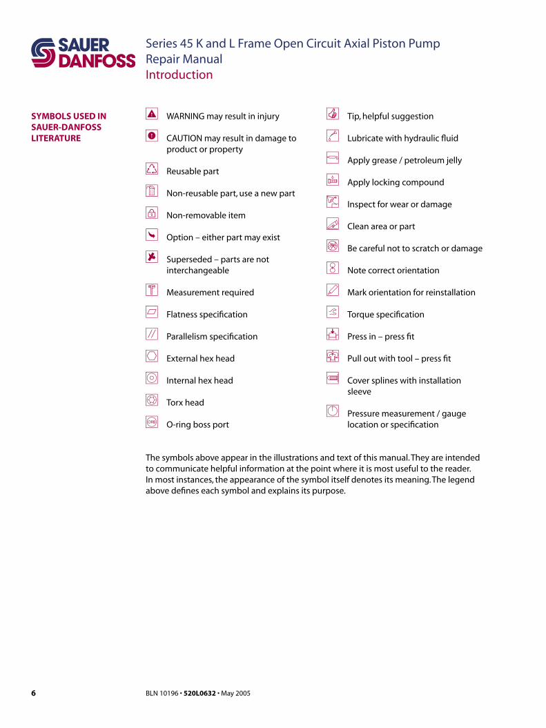
WARNING may result in injury
CAUTION may result in damage to product or property
Reusable part
Non-reusable part, use a new part
Non-removable item
Option – either part may exist
Superseded – parts are not interchangeable
Measurement required
Flatness specification
Parallelism specification
External hex head
Internal hex head
Torx head
O-ring boss port
Tip, helpful suggestion
Lubricate with hydraulic fluid
Apply grease / petroleum jelly
Apply locking compound
Inspect for wear or damage
Clean area or part
Be careful not to scratch or damage
Note correct orientation
Mark orientation for reinstallation
Torque specification
Press in – press fit
Pull out with tool – press fit
Cover splines with installation sleeve
Pressure measurement / gauge location or specification
SYMBOLS USED IN SAUER-DANFOSS LITERATURE
The symbols above appear in the illustrations and text of this manual. They are intended to communicate helpful information at the point where it is most useful to the reader. In most instances, the appearance of the symbol itself denotes its meaning. The legend above defines each symbol and explains its purpose.
7BLN 10196 • 520L0632 • May 2005
Series 45 K and L Frame Open Circuit Axial Piston PumpRepair ManualDisassembly
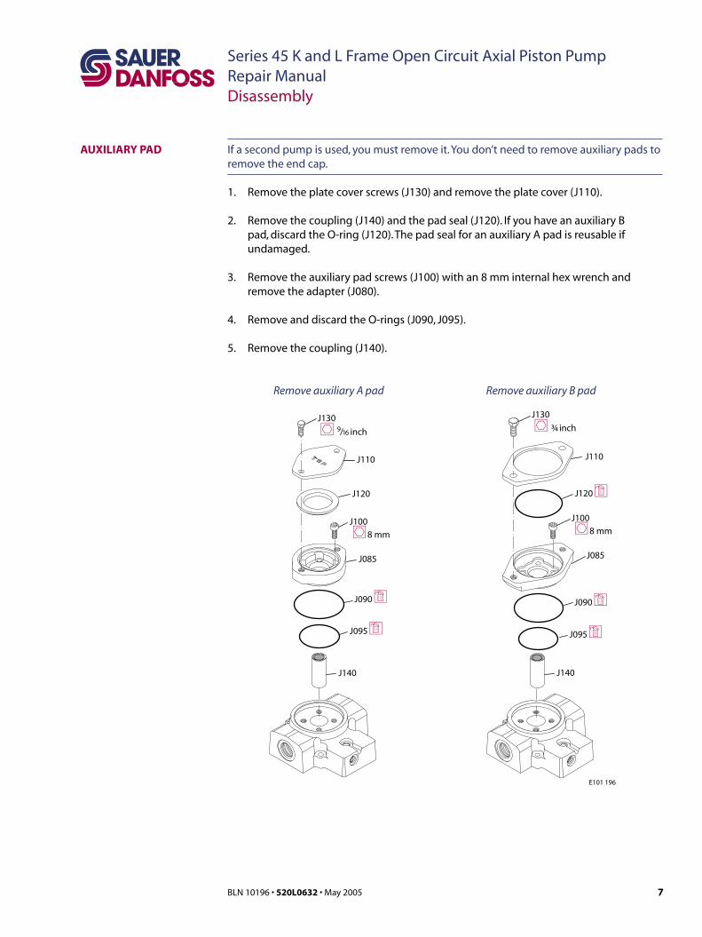
AUXILIARY PAD
J140
J095 d
J100
J090 d
J085
J120
J110
J130
J140
J095 d
J100
J090 d
J085
J120 d
J110
J130
h 9/16 inch h ¾ inch
h8 mm h8 mm
E101 196
Remove auxiliary A pad Remove auxiliary B pad
If a second pump is used, you must remove it. You don’t need to remove auxiliary pads to remove the end cap.
1. Remove the plate cover screws (J130) and remove the plate cover (J110).
2. Remove the coupling (J140) and the pad seal (J120). If you have an auxiliary B pad, discard the O-ring (J120). The pad seal for an auxiliary A pad is reusable if undamaged.
3. Remove the auxiliary pad screws (J100) with an 8 mm internal hex wrench and remove the adapter (J080).
4. Remove and discard the O-rings (J090, J095).
5. Remove the coupling (J140).

8 BLN 10196 • 520L0632 • May 2005
Series 45 K and L Frame Open Circuit Axial Piston PumpRepair ManualDisassembly
6. Using a 5 mm internal hex wrench, remove the 4 control screws (C300) that fasten the control assembly to the endcap (J020).
7. Remove the control from endcap. Discard interface O-rings. (C200).
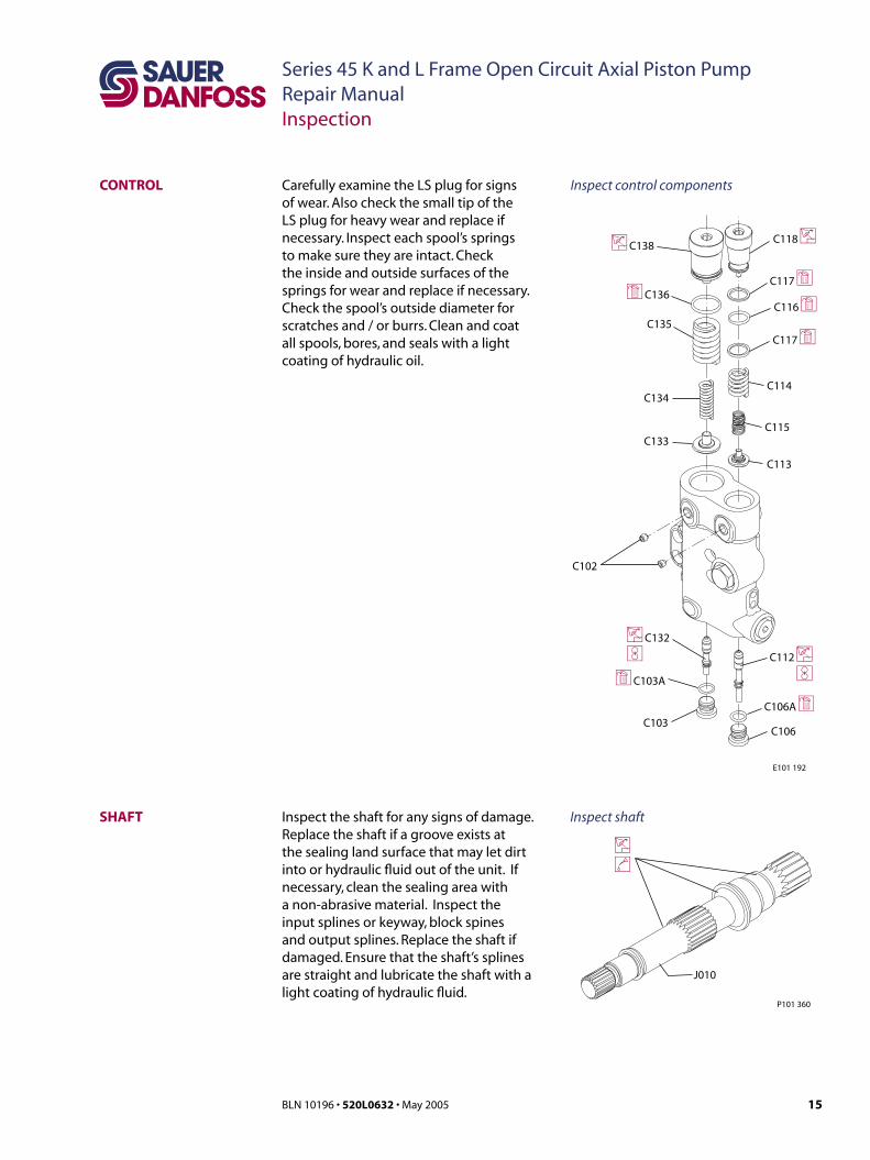
CONTROL
ENDCAP AND ROLLER BEARING
C200
C300I5 mm
d
P104 328
B045
B070
B020
B046
J030
I8 mm
J020
e
d
d
s
P101 351
B010
L020
L080
26 mm
Remove control
8. Remove the 4 endcap screws (J030) using an 8 mm internal hex wrench.
9. Remove the endcap. Remove the servo piston (L020) and guide (L080). Use care; valve plate (B070) may adhere to inside surface. Discard O-rings (B045, B046). Once the valve plate is removed, the check valve can be removed. Refer to Inspection, page 17, for more information.
To protect these parts from contamination, place the endcap and valve plate in a protected area.
10. Slide the rear tapered roller bearing cone (B020) from the bottom end of the shaft. The bearing cup (B010) may remain within the endcap.
Remove bearing cup if replacement is necessary. See Inspection, page 18.
Remove endcap and roller bearing
9BLN 10196 • 520L0632 • May 2005
Series 45 K and L Frame Open Circuit Axial Piston PumpRepair ManualDisassembly
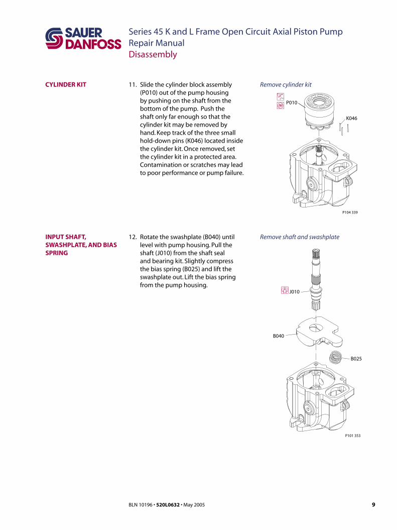
CYLINDER KIT 11. Slide the cylinder block assembly (P010) out of the pump housing by pushing on the shaft from the bottom of the pump. Push the shaft only far enough so that the cylinder kit may be removed by hand. Keep track of the three small hold-down pins (K046) located inside the cylinder kit. Once removed, set the cylinder kit in a protected area. Contamination or scratches may lead to poor performance or pump failure.
P010i
s
K046
P104 339
Remove cylinder kit
INPUT SHAFT, SWASHPLATE, AND BIAS SPRING
pJ010
B040
B025
P101 353
12. Rotate the swashplate (B040) until level with pump housing. Pull the shaft (J010) from the shaft seal and bearing kit. Slightly compress the bias spring (B025) and lift the swashplate out. Lift the bias spring from the pump housing.
Remove shaft and swashplate

10 BLN 10196 • 520L0632 • May 2005
Series 45 K and L Frame Open Circuit Axial Piston PumpRepair ManualDisassembly
13. Pull to remove the front tapered roller bearing (B050). Carefully pry to remove the journal bearings (B030) and retaining pins (B071) from the pump housing. Record the location and orientation of the journal bearings if they are to be reused. If necessary, remove the front bearing cup (B060) from the pump housing.
SHAFT SEAL
ROLLER BEARING, CUP, AND JOURNAL BEARINGS
P101 352
K020 p
K010
B071
B030
B050
pB060
m
p
P101 369
14. Orient the housing with the flange facing up. Using snap-ring pliers, remove the snap ring (K010). Carefully pry out the shaft seal (K020).
If you are unable to pull the shaft seal out, try to push the seal out by going through the inside of the housing.
Remove bearings
Remove shaft seal

11BLN 10196 • 520L0632 • May 2005
Series 45 K and L Frame Open Circuit Axial Piston PumpRepair ManualDisassembly
CONTROL HOUSING
C112 i
C106A d
iC132
C103
dC103A
C133
C113
C134
C115
C114
C135
C117 d
dC136C116 d
C117 d
C118 iiC138
E101 192
R
R
C102
C106
Disassemble control
C CautionIf removing the LS or PC spool is not possible, be extremely careful when
flipping or relocating the housing as not to lose or
damage the spool.
15. With a 3/16 inch internal hex wrench, remove the plugs (C103, C106) and their O-rings. Discard the O-rings. Remove the 2 set screws (C102). Remove the spool (C112). Note the orientation of the spools for reinsertion. There may be differences in reinserting into the same bore. Remove the spool (C132). C
The PC and LS spools are not the same. They must be identified as to which bore they come out of.
16. Remove the adjusting screw (C138) and the O-ring (C138A). Discard the O-ring. Remove the springs (C134, C135) and spring guide (C133).
17. Remove the adjusting screw (C118), O-ring (C116) and 2 backup rings (C117). Discard the O-ring and backup rings. Remove the springs (C114, C115) and spring guide (C113).

12 BLN 10196 • 520L0632 • May 2005
Series 45 K and L Frame Open Circuit Axial Piston PumpRepair ManualDisassembly
K045
K044
K043
K042
K041
P010
K047 l
K049 l
K050 l
P101 356
K046
K048 (L Frame only)
Disassemble cylinder kitCYLINDER KIT DISASSEMBLY
18. Remove pistons (K050) and slipper retainer (K049) from the cylinder block.
The pistons are not selectively fitted, however units with high hourly usage may develop wear patterns. Number the pistons and bores for reassembly if they are to be reused.
19. Remove the ball guide (K047), hold-down pins (K046), and retaining ring (K048) from the cylinder block (K041).
Most repairs do not require block spring removal. Perform this procedure only if you suspect problems with the block spring.
Block spring removal20. Turn the block over. Using a press,
apply pressure on the block spring washer (K044)) to compress the block spring (K043). Compress the spring enough to safely remove the spiral retaining ring (K045). While maintaining pressure, unwind the
W WarningRisk of personal injury:
Compressing the block spring requires about 350
to 400 N [80 to 90 lbf ]. Use a press sufficient to maintain this force
with reasonable effort. Ensure the spring is
secure before attempting to remove the spiral
retaining ring. Release the pressure slowly after the
retaining ring is removed.
spiral retaining ring. Carefully release the pressure and remove the outer block spring washer, block spring , and inner block spring washer (K042) from the cylinder block. W

13BLN 10196 • 520L0632 • May 2005
Series 45 K and L Frame Open Circuit Axial Piston PumpRepair ManualInspection
BALL GUIDE, SLIPPERRETAINER, AND HOLD-DOWN PINS
i
Slipperretainer
Ball guide
Hold down pins
P101 471
The ball guide should be free of nicks and scratches, and should not be excessively scored. Examine for discoloration that may indicate excessive heat or lack of lubrication. The slipper retainer should be flat, and slippers should fit in the retainer with minimal side play. Place the hold-down pins on a flat surface and roll them to make sure they are straight. Discard and replace any damaged parts.
K Frame
Slipperfoot thickness 4.03 mm
[0.159 in]
Piston/slipper end play 0.102 mm
[0.004 in]
L Frame
Slipperfoot thickness 2.67 mm
[0.105 in]
Piston/slipper end play 0.102 mm
[0.004 in]
Inspect guide, retainer, and pins
OVERVIEW After disassembly, wash all parts (including the end-cap and housing) thoroughly with clean solvent and allow to air dry. Blow out oil passages in the housing and endcap with compressed air. Conduct inspection in a clean area and keep all parts free from contamination. Clean and dry parts again after any rework or resurfacing.
PISTONS AND SLIPPERS Inspect the pistons for damage and discoloration. Discolored pistons may indicate excessive heat; do not reuse.
Inspect the running surface of the slippers. Replace any piston assemblies with scored or excessively rounded slipper edges. Measure the slipper foot thickness. Replace any piston assemblies with excessively worn slippers. Check the slipper axial end-play. Replace any piston assemblies with excessive end-play.
Minimum slipper foot thickness and maximum axial end-play are given in the table to the right.
K050
Slipper
Maximum end play
Minimumslipper footthickness
P104 109E
Inspect pistons

14 BLN 10196 • 520L0632 • May 2005
Series 45 K and L Frame Open Circuit Axial Piston PumpRepair ManualInspection
BLOCK SPRING, AND WASHERS
iWasher
Cylinder block spring
Spring retainer
Retaining ring
P101 472
If cylinder kit was fully dissembled, visual inspection of the cylinder block, spring, and washers should indicate minimal wear. Replace if cracks or other damage is present.
CYLINDER BLOCK Examine the running face of the cylinder block. The surface should be smooth and free of nicks and burrs. Ensure that no scratches or grooves exist; these may drastically reduce output flow.
C100
A
flat to 0.002 mm
[flat to 0.000080 in]
M
i
fP101 358
MB
K Frame 38 cc 45 cc
Minimum cylinder
block height (A)
56.48 mm
[2.224 in]
Maximum block bore
diameter (B)
16.44 mm
[0.65 in]
17.98 mm
[0.71 in]
L Frame 25 cc 30 cc
Minimum cylinder
block height (A)
50.8 mm
[2.00 in]
Maximum block bore
diameter (B)
13.88 mm
[0.546 in]
15.22 mm
[0.60 in]
Inspect block spring and washers
Inspect cylinder block
15BLN 10196 • 520L0632 • May 2005
Series 45 K and L Frame Open Circuit Axial Piston PumpRepair ManualInspection
Inspect the shaft for any signs of damage. Replace the shaft if a groove exists at the sealing land surface that may let dirt into or hydraulic fluid out of the unit. If necessary, clean the sealing area with a non-abrasive material. Inspect the input splines or keyway, block spines and output splines. Replace the shaft if damaged. Ensure that the shaft’s splines are straight and lubricate the shaft with a light coating of hydraulic fluid.
SHAFT
J010
i
P101 360
l
Inspect shaft
CONTROL
C112 i
C106A d
iC132
C103
dC103A
C133
C113
C134
C115
C114
C135
C117 d
dC136C116 d
C117 d
C118 iiC138
E101 192
R
R
C102
C106
Carefully examine the LS plug for signs of wear. Also check the small tip of the LS plug for heavy wear and replace if necessary. Inspect each spool’s springs to make sure they are intact. Check the inside and outside surfaces of the springs for wear and replace if necessary. Check the spool’s outside diameter for scratches and / or burrs. Clean and coat all spools, bores, and seals with a light coating of hydraulic oil.
Inspect control components
16 BLN 10196 • 520L0632 • May 2005
Series 45 K and L Frame Open Circuit Axial Piston PumpRepair ManualInspection
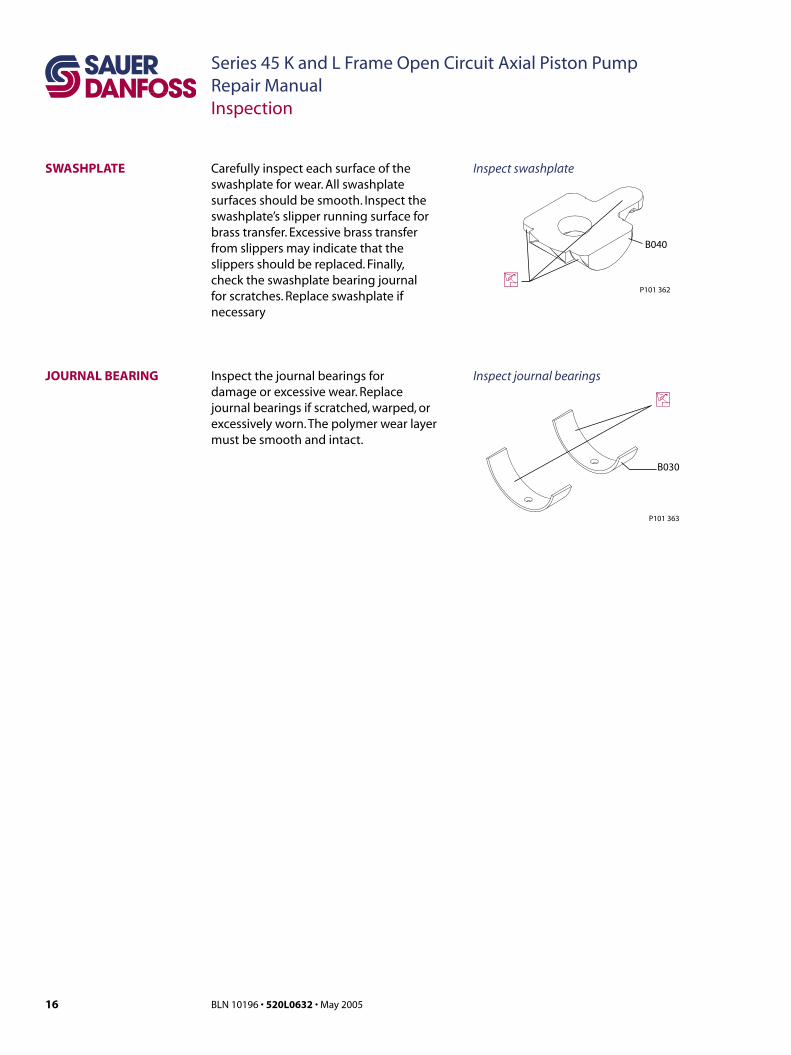
SWASHPLATE
iP101 362
B040
JOURNAL BEARING
B030
i
P101 363
Carefully inspect each surface of the swashplate for wear. All swashplate surfaces should be smooth. Inspect the swashplate’s slipper running surface for brass transfer. Excessive brass transfer from slippers may indicate that the slippers should be replaced. Finally, check the swashplate bearing journal for scratches. Replace swashplate if necessary
Inspect swashplate
Inspect journal bearingsInspect the journal bearings for damage or excessive wear. Replace journal bearings if scratched, warped, or excessively worn. The polymer wear layer must be smooth and intact.
17BLN 10196 • 520L0632 • May 2005
Series 45 K and L Frame Open Circuit Axial Piston PumpRepair ManualInspection
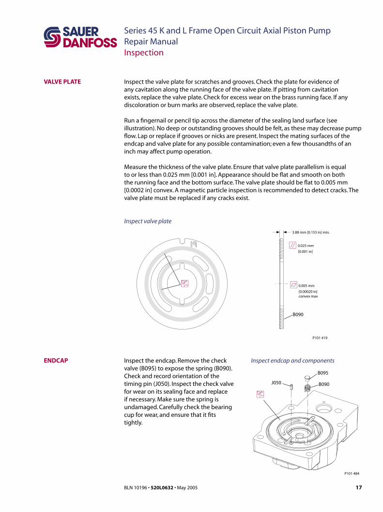
ENDCAP
B095
B090
P101 484
i
J050
Inspect the endcap. Remove the check valve (B095) to expose the spring (B090). Check and record orientation of the timing pin (J050). Inspect the check valve for wear on its sealing face and replace if necessary. Make sure the spring is undamaged. Carefully check the bearing cup for wear, and ensure that it fits tightly.
Inspect endcap and components
Inspect the valve plate for scratches and grooves. Check the plate for evidence of any cavitation along the running face of the valve plate. If pitting from cavitation exists, replace the valve plate. Check for excess wear on the brass running face. If any discoloration or burn marks are observed, replace the valve plate.
Run a fingernail or pencil tip across the diameter of the sealing land surface (see illustration). No deep or outstanding grooves should be felt, as these may decrease pump flow. Lap or replace if grooves or nicks are present. Inspect the mating surfaces of the endcap and valve plate for any possible contamination; even a few thousandths of an inch may affect pump operation.
VALVE PLATE
Inspect valve plate
Measure the thickness of the valve plate. Ensure that valve plate parallelism is equal to or less than 0.025 mm [0.001 in]. Appearance should be flat and smooth on both the running face and the bottom surface. The valve plate should be flat to 0.005 mm [0.0002 in] convex. A magnetic particle inspection is recommended to detect cracks. The valve plate must be replaced if any cracks exist.
B090
3.88 mm [0.153 in] min.
0.025 mm
[0.001 in]
0.005 mm
[0.00020 in]convex max
i
a
f
P101 419

18 BLN 10196 • 520L0632 • May 2005
Series 45 K and L Frame Open Circuit Axial Piston PumpRepair ManualInspection
SHAFT BEARING KITS
il
e
P101 366
The tapered roller bearing kits consist of a cup and cone. Both the cup and cone should be free of excessive wear and contamination. Rotate the bearings to check for smoothness. If a contaminated bearing is suspected, clean with a solvent and lubricate with hydraulic fluid. If the problem is not remedied by cleaning, replace the bearing. Also inspect for uneven wear. If abnormal wear is found, replace the bearing kit.
Inspect shaft bearings
Inspect the servo piston guide (L080) for abnormal wear. Check the inside diameter of the bore for galling or excessive wear. Inspect the servo piston (L020) for wear on its end and for scratches along its cylindrical surface. Replace both parts if any wear is noticeable.
SERVO PISTON AND GUIDE
L080
L020
i
P101 365
Inspect servo piston and guide

19BLN 10196 • 520L0632 • May 2005
Series 45 K and L Frame Open Circuit Axial Piston PumpRepair ManualInspection
HOUSING
i
P101 489
Inspect the housing to ensure that it is clean and free of foreign material. Inspect the swashplate, bearing surfaces, and endcap mating surfaces.
Inspect housing
AUXILIARY PAD Inspect sealing surfaces on the endcap and auxiliary pad and make sure that they are clean and free of contaminants. Inspect the coupling (J140) for any signs of excessive or abnormal wear. Replace all O-rings. Replace excessively worn parts if necessary.
J140 i
J095 d
J100
J090 d
J085
J120
J110
J130
i
E101 197
Inspect auxiliary pad components
20 BLN 10196 • 520L0632 • May 2005
Series 45 K and L Frame Open Circuit Axial Piston PumpRepair ManualAssembly
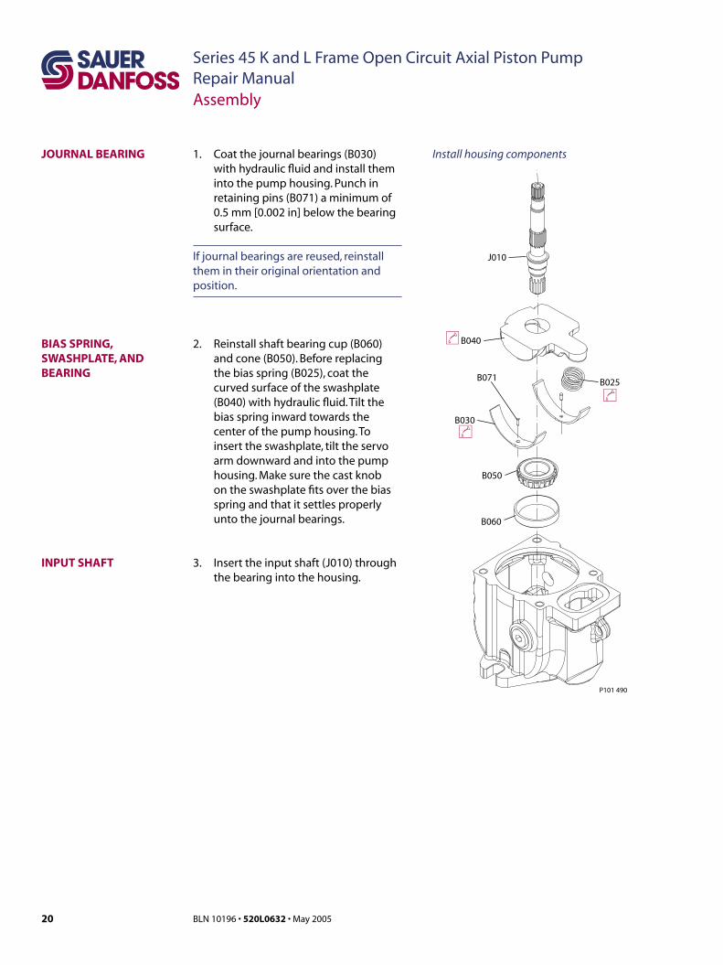
1. Coat the journal bearings (B030) with hydraulic fluid and install them into the pump housing. Punch in retaining pins (B071) a minimum of 0.5 mm [0.002 in] below the bearing surface.
If journal bearings are reused, reinstall them in their original orientation and position.
JOURNAL BEARING
INPUT SHAFT
BIAS SPRING, SWASHPLATE, AND BEARING
B060
B050
lB040
J010
B030
B025B071
l
l
P101 490
3. Insert the input shaft (J010) through the bearing into the housing.
2. Reinstall shaft bearing cup (B060) and cone (B050). Before replacing the bias spring (B025), coat the curved surface of the swashplate (B040) with hydraulic fluid. Tilt the bias spring inward towards the center of the pump housing. To insert the swashplate, tilt the servo arm downward and into the pump housing. Make sure the cast knob on the swashplate fits over the bias spring and that it settles properly unto the journal bearings.
Install housing components
21BLN 10196 • 520L0632 • May 2005
Series 45 K and L Frame Open Circuit Axial Piston PumpRepair ManualAssembly
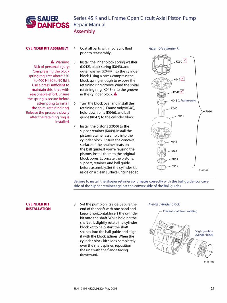
4. Coat all parts with hydraulic fluid prior to reassembly.
5. Install the inner block spring washer (K042), block spring (K043), and outer washer (K044) into the cylinder block. Using a press, compress the block spring enough to expose the retaining ring groove. Wind the spiral retaining ring (K045) into the groove in the cylinder block. W
6. Turn the block over and install the retaining ring (L Frame only; K048), hold-down pins (K046), and ball guide (K047) to the cylinder block.
7. Install the pistons (K050) to the slipper retainer (K049). Install the piston/retainer assembly into the cylinder block. Ensure the concave surface of the retainer seats on the ball guide. If you’re reusing the pistons, install them to the original block bores. Lubricate the pistons, slippers, retainer, and ball guide before assembly. Set the cylinder kit aside on a clean surface until needed.
K045
K044
K043
K042
K041
P010
K047 l
K049 l
K050 l
P101 356
K046
K048 (L Frame only)
Prevent shaft from rotating
P101 491E
Slightly rotatecylinder block
Assemble cylinder kit
Install cylinder block
CYLINDER KIT ASSEMBLY
W WarningRisk of personal injury:
Compressing the block spring requires about 350
to 400 N [80 to 90 lbf ]. Use a press sufficient to maintain this force with
reasonable effort. Ensure the spring is secure before
attempting to install the spiral retaining ring.
Release the pressure slowly after the retaining ring is
installed.
CYLINDER KIT INSTALLATION
Be sure to install the slipper retainer so it mates correctly with the ball guide (concave side of the slipper retainer against the convex side of the ball guide).
8. Set the pump on its side. Secure the end of the shaft with one hand and keep it horizontal. Insert the cylinder kit onto the shaft. While holding the shaft still, slightly rotate the cylinder block kit to help start the shaft splines into the ball guide and align it with the block splines. When the cylinder block kit slides completely over the shaft splines, reposition the unit with the flange facing downward.

22 BLN 10196 • 520L0632 • May 2005
Series 45 K and L Frame Open Circuit Axial Piston PumpRepair ManualAssembly
9. Install the inlet check valve spring (B090) and poppet (B095) into the endcap (J020). A small amount of grease will keep the poppet in position. Clean the valve plate (B070) and endcap (J020). Install the timing pin (J050) in the endcap and verify that it is properly oriented with the split facing into or out of the slot in the valve plate. The timing pin should be installed 3.6 ± 0.25 mm [0.14 ± 0.01 in] above the endcap surface. Apply a liberal amount of assembly grease to the backside of the valve plate surface to hold it in position. Install the valve plate over the timing pin, check valve, and bearing cup. Install the piston (L020) into the guide (L080), and torque the guide to 61 - 75 N•m [45 - 55 lbf•ft].
VALVE PLATE AND ENDCAP
eB070
J050 R
B020
eJ020B090
B095 g
P101 492
g
B010L080
L020
t61 - 75 N•m [45 -55 lbf•ft]
B045 g
gB046
J0308 mm47.5 to 61 N·m[35 to 45 lbf·ft]
J020
It
P101 493
Install endcap components
Install endcap10. Using assembly grease to hold seals, install the endcap to the housing. Ensure that seals remain properly seated and are not pinched during assembly. Install and torque endcap screws at 47.5 to 61 N•m [35 to 45 lbf•ft], using the criss cross pattern, and retorque the first screw to ensure proper torque retention.
23BLN 10196 • 520L0632 • May 2005
Series 45 K and L Frame Open Circuit Axial Piston PumpRepair ManualAssembly
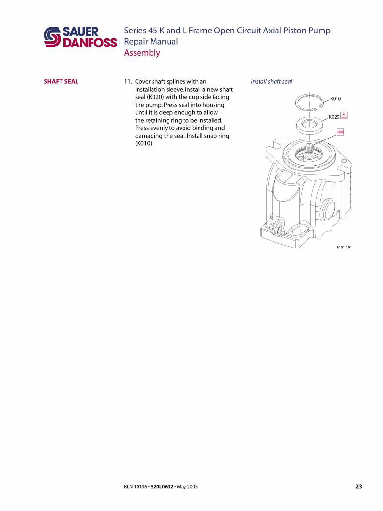
SHAFT SEAL 11. Cover shaft splines with an installation sleeve. Install a new shaft seal (K020) with the cup side facing the pump. Press seal into housing until it is deep enough to allow the retaining ring to be installed. Press evenly to avoid binding and damaging the seal. Install snap ring (K010).
Install shaft seal
E101 191
K020 P
K010
24 BLN 10196 • 520L0632 • May 2005
Series 45 K and L Frame Open Circuit Axial Piston PumpRepair ManualAssembly
12. Clean and lubricate all control parts and cover with a light coating of hydraulic fluid prior to reassembly.
13. Hold the control in a horizontal position. Install the spherical end of the LS spool (C112) into the LS bore (see illustration). Using a new O-ring, install the LS plug (C106), torque at 10.8 to 13.5 N•m [8 to 10 lbf•ft]. Place the two LS springs (C115, C114) onto the LS spring guide (C113) and install into the LS bore. Place a new O-ring (C116) and back-up rings (C117) onto the LS adjustment screw (C118). Install the LS plug assembly so that it sits one turn below the surface of the control housing. Install and tighten set screw (C102) at 7.5 to 10.8 N•m [5.5 to 8 lbf•ft].
CONTROL
C112 i
C106A d
iC132
C103
dC103A
C133
C113
C134
C115
C114
C135
C117 d
dC136C116 d
C117 d
C118 iiC138
P101 370
R
R
C102
t7.5 to 10.8 N•m [5.5 to 8.0 lbf•ft]
t10.8 to 13.5 N•m [8 to 10 lbf•ft] (C103 and C106)
C106
C200
C300I5 mm
d
P101 367
t15 to 18 N•m [11 to 13 lbf•ft]
15. Using petroleum jelly to retain them, Install the 3 seal rings (C200) in the recesses on the control housing. Install the control assembly onto the endcap using the 4 screws. Torque at 15 to 18 N•m [11 to 13 lbf•ft] using a criss cross pattern and retorque the first screw to ensure proper torque retention.
14. Install the spherical end of the PC spool (C132) into the PC bore (refer to illustration). Install the PC plug (C103) using a new O-ring. Torque at 10.8 to 13.5 N•m [8 to 10 lbf•ft]. Place the two PC springs (C134, C135) onto the PC spring guide (C133) and install into the PC bore. Place a new O-ring onto the PC plug (C138) and install it so that it sits one turn below the surface of the control housing. Install and tighten set screw (C102) at 7.5 to 10.8 N•m [5.5 to 8 lbf•ft]. to retain the adjusting plug.
Assemble the control
Install the control
PC and LS spools need to be adjusted to proper setting according to tag
nomenclature

25BLN 10196 • 520L0632 • May 2005
Series 45 K and L Frame Open Circuit Axial Piston PumpRepair ManualAssembly
AUXILIARY PAD 16. Install the adapter (J085) with new O-rings (J090, J095). Tighten the screws (J100) at 67.5 to 82.5 N•m [49.8 to 60.8 lbf•ft].
17. Install the coupling (J140) onto the shaft.
18. Install the seal (J120) and plate cover (J130). If you have auxiliary pad B, install a new O-ring (J120). Tighten the plate cover screws (J130) to the specifications shown in the drawings below.
J140 i
J095 d
J100
J090 d
J085
J120
J110
J130
E101 198
t36.6 to 50.1 N•m [27.0 to 37.0 lbf•ft]
t67.5 to 82.5 N•m [49.8 to 60.8 lbf•ft]
Install auxiliary A pad
J140
J095 d
J100
J090 d
J085
J120 d
J110
J130
t61 to 73 N•m [45 to 54 lbf•ft]
t67.5 to 82.5 N•m [49.8 to 60.8 lbf•ft]
E101 223
Install auxiliary B pad
26 BLN 10196 • 520L0632 • May 2005
Series 45 K and L Frame Open Circuit Axial Piston PumpRepair ManualNotes

27BLN 10196 • 520L0632 • May 2005
Series 45 K and L Frame Open Circuit Axial Piston PumpRepair ManualNotes
Sauer-Danfoss Mobile Power and Control Systems– Market Leaders Worldwide
Sauer-Danfoss is a comprehensive supplier providing complete systems to the global mobile market.
Sauer-Danfoss serves markets such as agriculture, construction, road building, material handling, municipal, forestry, turf care, and many others.
We offer our customers optimum solutions for their needs and develop new products and systems in close cooperation and partnership with them.
Sauer-Danfoss specializes in integrating a full range of system components to provide vehicle designers with the most advanced total system design.
Sauer-Danfoss provides comprehensive worldwide service for its products through an extensive network of Authorized Service Centers strategically located in all parts of the world.
Sauer-Danfoss (US) Company2800 East 13th StreetAmes, IA 50010, USAPhone: +1 515 239-6000, Fax: +1 515 239 6618
Sauer-Danfoss GmbH & Co. OHGPostfach 2460, D-24531 NeumünsterKrokamp 35, D-24539 Neumünster, GermanyPhone: +49 4321 871-0, Fax: +49 4321 871 122
Sauer-Danfoss ApSDK-6430 Nordborg, DenmarkPhone: +45 7488 4444, Fax: +45 7488 4400
www.sauer-danfoss.com
OUR PRODUCTS
Hydrostatic transmissions
Hydraulic power steering
Electric power steering
Electrohydraulic power steering
Closed and open circuit axial piston pumps and motors
Gear pumps and motors
Bent axis motors
Orbital motors
Transit mixer drives
Planetary compact gears
Proportional valves
Directional spool valves
Cartridge valves
Hydraulic integrated circuits
Hydrostatic transaxles
Integrated systems
Fan drive systems
Electrohydraulics
Microcontrollers and software
Electric motors and inverters
Joysticks and control handles
Displays
Sensors
BLN 10196 • 520L0632 • May 2005
JLG/0505