Embed Size (px)
Citation preview

The World Leading Air-conditioning Company
42CET/ 42CED Series Chilled Water Fan Coil Unit Furred-in Ceiling Model 300 to 1400 cfm Electric heater option
42DC/ 42DCD Series Chilled Water Fan Coil Unit Furred-in Ceiling Model 600 to 2000 cfm Electric heater option
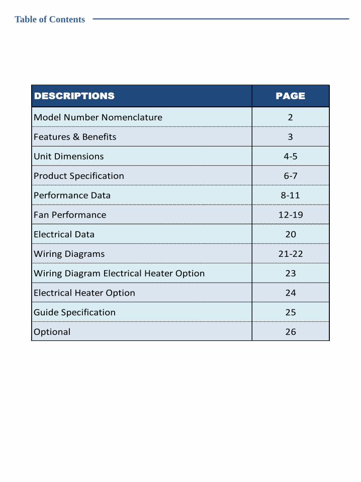
Table of Contents
DESCRIPTIONS PAGE
Model Number Nomenclature 2
Features & Benefits 3
Unit Dimensions 4-5
Product Specification 6-7
Performance Data 8-11
Fan Performance 12-19
Electrical Data 20
Wiring Diagrams 21-22
Wiring Diagram Electrical Heater Option 23
Electrical Heater Option 24
Guide Specification 25
Optional 26
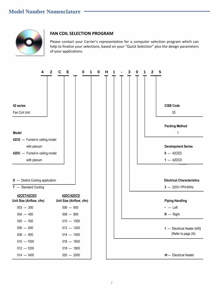
FAN COIL SELECTION PROGRAM
Please contact your Carrier’s representative for a computer selection program which can help to finalize your selections, based on your “Quick Selection” plus the design parameters of your applications.
2
4 2 C E 0 1 0 H 1 - 3 0 1 2 5
42 series CISB Code
Fan Coil Unit 25
Packing Method
Model 1
42CE — Furred-in ceiling model
with plenum Development Series
42DC — Furred-in ceiling model 0 — 42CED
with plenum 1 — 42DCD
D — District Cooling application Electrical Characteristics
3 — 220V-1PH-60Hz
Unit Size (Airflow, cfm) Piping Handling
- — Left
R — Right
H — Electrical Heater
006 — 600
008 — 800
006 — 600
008 — 800
010 — 1000
010 — 1000
012 — 1200
014 — 1400
012 — 1200
42CET/42CED 42DC/42DCD
018 — 1800
014 — 1400 020 — 2000
016 — 1600
003 — 300
004 — 400
005 — 500
T — Standard Cooling
1 — Electrical Heater (kW)
(Refer to page 24)
Unit Size (Airflow, cfm)
Model Number Nomenclature
Features & Benefits
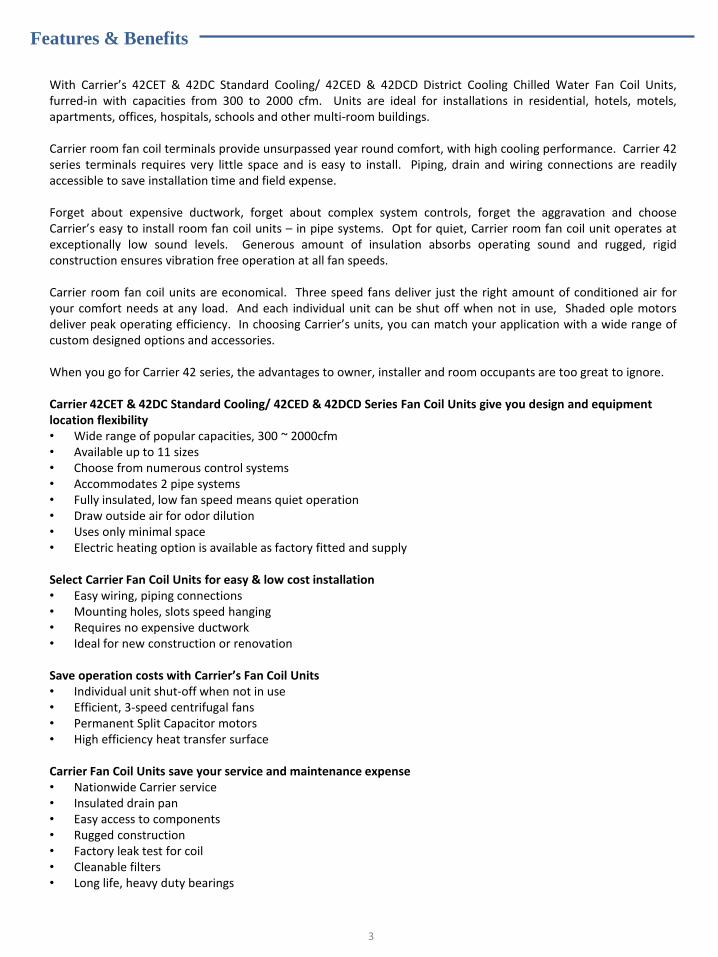
With Carrier’s 42CET & 42DC Standard Cooling/ 42CED & 42DCD District Cooling Chilled Water Fan Coil Units, furred-in with capacities from 300 to 2000 cfm. Units are ideal for installations in residential, hotels, motels, apartments, offices, hospitals, schools and other multi-room buildings. Carrier room fan coil terminals provide unsurpassed year round comfort, with high cooling performance. Carrier 42 series terminals requires very little space and is easy to install. Piping, drain and wiring connections are readily accessible to save installation time and field expense. Forget about expensive ductwork, forget about complex system controls, forget the aggravation and choose Carrier’s easy to install room fan coil units – in pipe systems. Opt for quiet, Carrier room fan coil unit operates at exceptionally low sound levels. Generous amount of insulation absorbs operating sound and rugged, rigid construction ensures vibration free operation at all fan speeds. Carrier room fan coil units are economical. Three speed fans deliver just the right amount of conditioned air for your comfort needs at any load. And each individual unit can be shut off when not in use, Shaded ople motors deliver peak operating efficiency. In choosing Carrier’s units, you can match your application with a wide range of custom designed options and accessories. When you go for Carrier 42 series, the advantages to owner, installer and room occupants are too great to ignore. Carrier 42CET & 42DC Standard Cooling/ 42CED & 42DCD Series Fan Coil Units give you design and equipment location flexibility • Wide range of popular capacities, 300 ~ 2000cfm • Available up to 11 sizes • Choose from numerous control systems • Accommodates 2 pipe systems • Fully insulated, low fan speed means quiet operation • Draw outside air for odor dilution • Uses only minimal space • Electric heating option is available as factory fitted and supply
Select Carrier Fan Coil Units for easy & low cost installation • Easy wiring, piping connections • Mounting holes, slots speed hanging • Requires no expensive ductwork • Ideal for new construction or renovation
Save operation costs with Carrier’s Fan Coil Units • Individual unit shut-off when not in use • Efficient, 3-speed centrifugal fans • Permanent Split Capacitor motors • High efficiency heat transfer surface
Carrier Fan Coil Units save your service and maintenance expense • Nationwide Carrier service • Insulated drain pan • Easy access to components • Rugged construction • Factory leak test for coil • Cleanable filters • Long life, heavy duty bearings
3
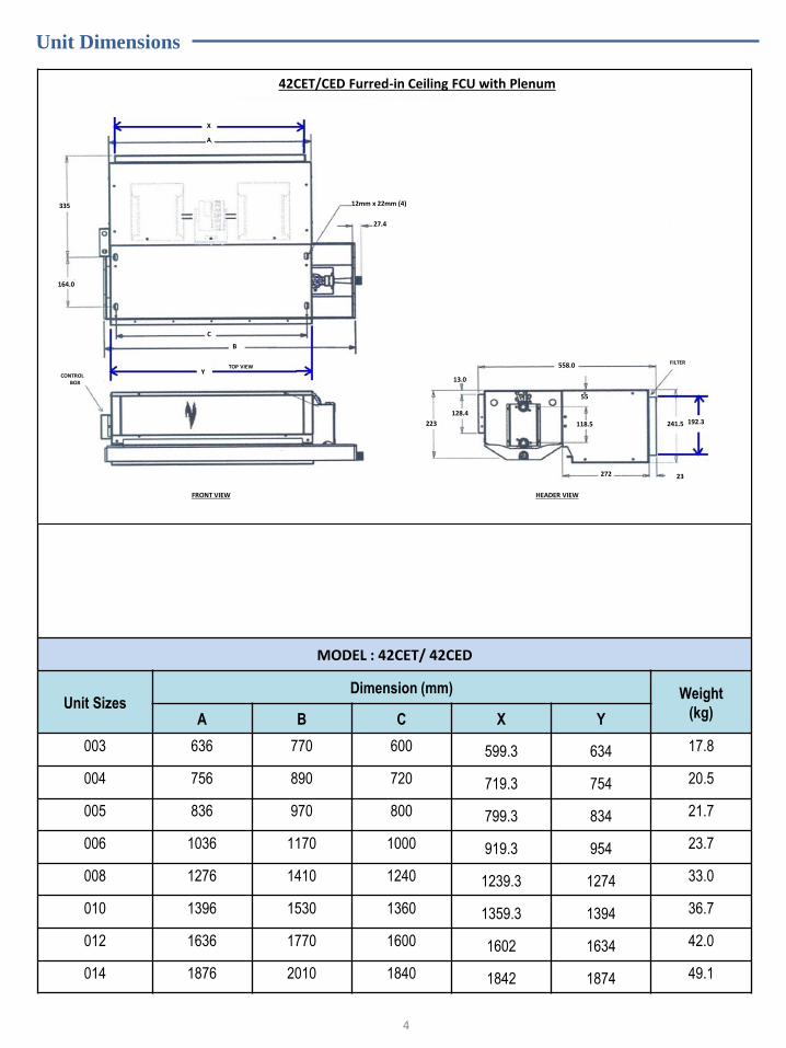
MODEL : 42CET/ 42CED
Unit Sizes Dimension (mm) Weight
(kg) A B C X Y
003 636 770 600 599.3 634 17.8
004 756 890 720 719.3 754 20.5
005 836 970 800 799.3 834 21.7
006 1036 1170 1000 919.3 954 23.7
008 1276 1410 1240 1239.3 1274 33.0
010 1396 1530 1360 1359.3 1394 36.7
012 1636 1770 1600 1602 1634 42.0
014 1876 2010 1840 1842 1874 49.1
4
42CET/CED Furred-in Ceiling FCU with Plenum
335
164.0
12mm x 22mm (4)
27.4
A
C
B
CONTROL BOX
TOP VIEW
FRONT VIEW HEADER VIEW
223
13.0
128.4
558.0 FILTER
241.5 118.5
55
272 23
192.3
Y
X
Unit Dimensions

MODEL : 42DC/ 42DCD
Unit Sizes Dimension (mm) Weight
(kg) A B C D E F
006 584 356 381 432 533 641 41
008 711 483 508 559 660 768 46
010 813 584 610 660 762 870 66
012 940 711 737 737 889 997 76
014 1067 838 864 914 1016 1124 78
016 1194 965 991 1041 1143 1251 79
018 1321 1092 1178 1168 1270 1378 86
020 1422 1194 1219 1270 1372 1479 98
5
42DC/DCD Furred-in Ceiling FCU with Plenum
F
F
D
683
C
B
A
114 114 32
183.4
583.7
134
268
402 306
13 142 104
423
64
36
356
FILTER REMOVAL
114
683
F D
183.4
114 32
C
B
A
D
683
114
C
B 114
183.4
32
MTG HOLE
CONTROL BOX
Unit Dimensions

Product Specification
Model: 42CED District Cooling Application
Description DUCTED CHILLED WATER FAN COIL UNIT
Model 42CED003 42CED004 42CED005 42CED006 42CED008 42CED010 42CED012 42CED014
Nominal Air Volume cfm 300 400 500 600 800 1000 1200 1400
l/s 142 189 236 283 378 472 566 661
Fluid Cooling Capacity* kW 2.21 3.17 3.36 3.61 5.44 5.87 6.41 7.77
Btu/hr 7,539 10,823 11,465 12,325 18,551 20,043 21,868 26,505
Motor Type Permanent Split Capacitor
Motor Nominal Power Output Watts 30 51 55 52 2 x 46 2 x 55 2 x 52 3 x 48
Motor Nominal Current amp 0.36 0.51 0.49 0.52 0.96 0.98 1.04 1.65
Fan Type Centrifugal Forward Curved Blades
Sound Pressure
**
High dB(A) 37.1 37.4 39.1 40.4 41.3 43.1 43.3 43.5
Med dB(A) 34.6 34.9 35.8 38.8 38.8 40.8 39.9 41.8
Low dB(A) 33.0 32.1 32.4 35.4 34.6 37.2 37.6 39.8
Water Flow l/s 0.06 0.09 0.09 0.10 0.15 0.16 0.17 0.21
Water Pressure Drop kPa 4.4 10.7 5.9 5.3 12.1 15.2 7.4 12.2
Coil Row / FPI 4 / 14
Working Pressure 1.72 Mpa
Connection In-out (sweat) / Material ¾” FPT (BSP) / Brass
Condensate Drain / Material ¾” MPT (BSP) / GI Steel
Note:
* Base on motor at high speed, standard air and dry coil operation, 8.9°C water temperature rise; entering air temperature 24.4°C DB; 17.2°C WB, Entering
water temperature 5.5°C.
** Sound measurement in accordance with Standard JIS8616-2006 (1.5m below the unit bottom).
Model: 42DCD District Cooling Application
Description DUCTED CHILLED WATER FAN COIL UNIT
Model 42DCD006 42DCD008 42DCD010 42DCD012 42DCD014 42DCD016 42DCD018 42DCD020
Nominal Air Volume Cfm 600 800 1000 1200 1400 1600 1800 2000
l/s 283 378 472 566 661 755 852 943
Fluid Cooling Capacity* kW 4.42 6.57 7.43 9.85 10.79 13.69 14.76 15.50
Btu/hr 15,076 22,428 25,365 33,597 36,799 46,716 50,362 52,887
Motor Type Permanent Split Capacitor
Motor Nominal Power Output Watts 118 118 200 118 (x2) 300 450 450 450
Motor Nominal Current Amp 1.11 1.11 1.9 1.11 (x2) 2.24 2.89 2.89 2.89
Fan Type Centrifugal Forward Curved Blades
Sound Pressure
**
High dB(A) 40.3 42.0 48.4 47.2 49.2 48.6 48.9 49.7
Med dB(A) 38.3 38.9 44.8 43.1 46.4 46.9 47.6 48.1
Low dB(A) 35.5 36.5 38.6 39.8 44.6 44.8 44.7 45.6
Water Flow ℓ/s 0.12 0.18 0.20 0.26 0.29 0.37 0.40 0.42
Water Pressure Drop kPa 22.2 54.4 46.8 49.9 39.0 50.7 60.2 54.3
Coil Row / FPI 4 / 14
Working Pressure 1.72 Mpa
Connection In-out (sweat)/Material 5/8” / Copper 1” / Copper
Condensate Drain/Material 7/8” / GI Steel
6
Product Specification
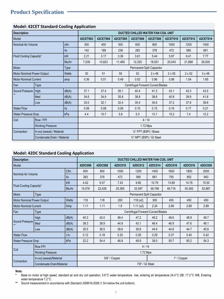
Model: 42CET Standard Cooling Application
Description DUCTED CHILLED WATER FAN COIL UNIT
Model 42CET003 42CET004 42CET005 42CET006 42CET008 42CET010 42CET012 42CET014
Nominal Air Volume cfm 300 400 500 600 800 1000 1200 1400
l/s 142 189 236 283 378 472 566 661
Fluid Cooling Capacity* kW 2.21 3.17 3.36 3.61 5.44 5.87 6.41 7.77
Btu/hr 7,539 10,823 11,465 12,325 18,551 20,043 21,868 26,505
Motor Type Permanent Split Capacitor
Motor Nominal Power Output Watts 30 51 55 52 2 x 46 2 x 55 2 x 52 3 x 48
Motor Nominal Current amp 0.36 0.51 0.49 0.52 0.96 0.98 1.04 1.65
Fan Type Centrifugal Forward Curved Blades
Sound Pressure
**
High dB(A) 37.1 37.4 39.1 40.4 41.3 43.1 43.3 43.5
Med dB(A) 34.6 34.9 35.8 38.8 38.8 40.8 39.9 41.8
Low dB(A) 33.0 32.1 32.4 35.4 34.6 37.2 37.6 39.8
Water Flow l/s 0.06 0.09 0.09 0.10 0.15 0.16 0.17 0.21
Water Pressure Drop kPa 4.4 10.7 5.9 5.3 12.1 15.2 7.4 12.2
Coil Row / FPI 4 / 14
Working Pressure 1.72 Mpa
Connection In-out (sweat) / Material ¾” FPT (BSP) / Brass
Condensate Drain / Material ¾” MPT (BSP) / GI Steel
Note:
* Base on motor at high speed, standard air and dry coil operation, 5.6°C water temperature rise; entering air temperature 24.4°C DB; 17.2°C WB, Entering
water temperature 7.2°C.
** Sound measurement in accordance with Standard JIS8616-2006 (1.5m below the unit bottom).
Model: 42DC Standard Cooling Application
Description DUCTED CHILLED WATER FAN COIL UNIT
Model 42DC006 42DC008 42DC010 42DC012 42DC014 42DC016 42DC018 42DC020
Nominal Air Volume Cfm 600 800 1000 1200 1400 1600 1800 2000
l/s 283 378 472 566 661 755 852 943
Fluid Cooling Capacity* kW 4.42 6.57 7.43 9.85 10.79 13.69 14.76 15.50
Btu/hr 15,076 22,428 25,365 33,597 36,799 46,716 50,362 52,887
Motor Type Permanent Split Capacitor
Motor Nominal Power Output Watts 118 118 200 118 (x2) 300 450 450 450
Motor Nominal Current Amp 1.11 1.11 1.9 1.11 (x2) 2.24 2.89 2.89 2.89
Fan Type Centrifugal Forward Curved Blades
Sound Pressure
**
High dB(A) 40.3 42.0 48.4 47.2 49.2 48.6 48.9 49.7
Med dB(A) 38.3 38.9 44.8 43.1 46.4 46.9 47.6 48.1
Low dB(A) 35.5 36.5 38.6 39.8 44.6 44.8 44.7 45.6
Water Flow ℓ/s 0.12 0.18 0.20 0.26 0.29 0.37 0.40 0.42
Water Pressure Drop kPa 22.2 54.4 46.8 49.9 39.0 50.7 60.2 54.3
Coil Row FPI 4 / 14
Working Pressure 1.72 Mpa
Connection In-out (sweat)/Material 5/8” / Copper 1” / Copper
Condensate Drain/Material 7/8” / GI Steel
7

Performance Data
Model : 42CED Furred-in Ceiling Model (60Hz motor) Unit
Sizes
Fan Speed ESP
Pa
Airflow
(ℓ/s)
Capacity (kW) Air Off FCU (°C) Water Flow
(ℓ/s)
Water Pressure
(kPa) Total Sensible DB WB
003
High
50
109 3.08 1.81 13.1 10.9 0.08 8.4
Medium 87 2.73 1.52 12.4 9.8 0.07 6.6
Low 63 2.09 1.18 11.6 9.3 0.06 3.9
004
High
50
159 4.39 2.62 13.3 11.2 0.12 20.5
Medium 119 3.73 2.09 12.3 9.8 0.1 14.9
Low 79 2.65 1.49 11.2 9.0 0.07 7.6
005
High
50
178 4.64 3.08 12.6 11.7 0.12 11.3
Medium 138 4.01 2.52 11.8 10.7 0.11 8.4
Low 94 2.88 1.85 10.7 10.2 0.08 4.4
006
High
50
212 5.07 3.37 13.7 12.5 0.14 10.3
Medium 190 4.77 3.1 13.4 12.0 0.13 9.1
Low 167 4.44 2.81 13.0 11.6 0.12 8.0
008
High
50
309 7.62 5.18 13.0 12.2 0.21 23.7
Medium 215 6.13 3.89 11.9 10.9 0.16 15.4
Low 148 4.44 2.84 11.0 10.3 0.12 8.1
010
High
50
347 8.13 5.46 13.9 12.6 0.22 28.5
Medium 271 7.01 4.49 13.2 11.8 0.19 21.5
Low 186 5.08 3.29 12.3 11.3 0.14 11.4
012
High
50
382 8.75 5.78 14.4 12.8 0.24 13.9
Medium 336 8.14 5.23 14.0 12.3 0.22 12.0
Low 296 7.28 4.71 13.7 12.2 0.2 9.6
014
High
50
455 10.46 6.95 14.2 12.8 0.28 21.6
Medium 383 9.44 6.08 13.7 12.2 0.25 17.7
Low 323 8.13 5.28 13.4 12.0 0.22 13.2
Note:
• Above based on operation with dry coils and clean air filter.
• Rating based on standard air and dry coil operation, 8.9°C water temperature rise; entering air temperature 19.4°C WB / 26.7°C DB, entering water
temperature 5.5°C.
8

Performance Data
Model : 42CET Furred-in Ceiling Model (60Hz motor)
Unit
Sizes Fan Speed
ESP
Pa
Airflow
(ℓ/s)
Capacity (kW) Air Off FCU (°C) Water Flow
(ℓ/s)
Water Pressure
(kPa) Total Sensible DB WB
003
High
50
109 3.21 1.97 11.9 10.5 0.14 12.1
Medium 87 2.84 1.66 11.1 9.3 0.12 9.6
Low 63 2.18 1.28 10.2 8.8 0.09 5.6
004
High
50
159 4.3 2.65 13.1 11.4 0.18 24.3
Medium 119 3.65 2.11 12.2 10.1 0.16 17.5
Low 79 2.59 1.51 11.0 9.3 0.11 8.9
005
High
50
178 4.52 2.99 13.0 12.0 0.19 17.2
Medium 138 3.91 2.45 12.2 11.0 0.17 12.8
Low 94 2.81 1.8 11.1 10.4 0.12 6.6
006
High
50
212 4.69 3.24 14.2 13.0 0.2 8.3
Medium 190 4.24 2.97 13.9 12.7 0.19 7.3
Low 167 4.11 2.69 13.5 12.2 0.18 6.4
008
High
50
309 7.28 5.03 13.4 12.6 0.31 16.1
Medium 215 5.85 3.78 12.3 11.3 0.25 10.6
Low 148 4.24 2.76 11.4 10.8 0.18 5.6
010
High
50
347 8.41 5.52 13.7 12.4 0.36 23.3
Medium 271 7.25 4.55 13.0 11.5 0.31 17.9
Low 186 5.25 3.33 12.1 11.0 0.22 9.5
012
High
50
382 10.2 6.38 13.1 1.5 0.44 24.5
Medium 336 9.49 5.77 12.7 11.0 0.41 21.7
Low 296 8.49 5.2 12.4 10.8 0.36 17.5
014
High
50
455 12.7 7.98 12.4 11.1 0.54 42.2
Medium 383 11.46 6.97 11.8 10.4 0.49 34.6
Low 323 9.87 6.06 11.4 10.2 0.42 26.1
Note:
• Above based on operation with dry coils and clean air filter.
• Rating based on standard air and dry coil operation, 5.6°C water temperature rise; entering air temperature 19.4°C WB / 26.7°C DB; entering water
temperature 7.2°C.
9
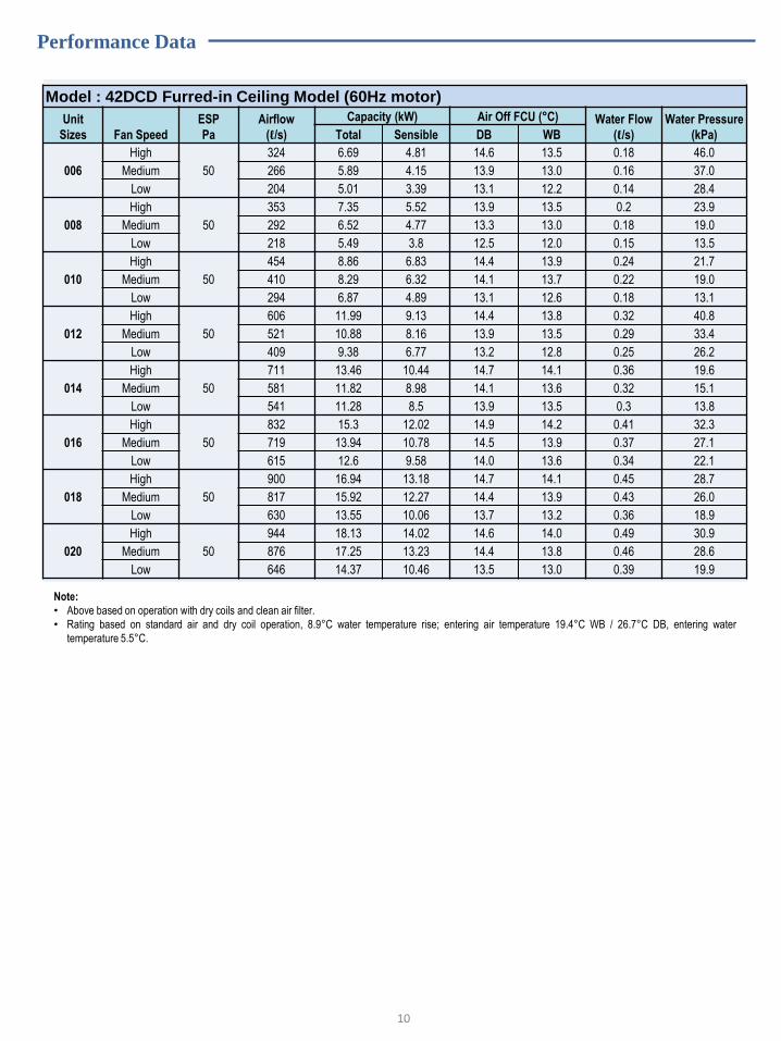
Performance Data
Model : 42DCD Furred-in Ceiling Model (60Hz motor)
Unit
Sizes Fan Speed
ESP
Pa
Airflow
(ℓ/s)
Capacity (kW) Air Off FCU (°C) Water Flow
(ℓ/s)
Water Pressure
(kPa) Total Sensible DB WB
006
High
50
324 6.69 4.81 14.6 13.5 0.18 46.0
Medium 266 5.89 4.15 13.9 13.0 0.16 37.0
Low 204 5.01 3.39 13.1 12.2 0.14 28.4
008
High
50
353 7.35 5.52 13.9 13.5 0.2 23.9
Medium 292 6.52 4.77 13.3 13.0 0.18 19.0
Low 218 5.49 3.8 12.5 12.0 0.15 13.5
010
High
50
454 8.86 6.83 14.4 13.9 0.24 21.7
Medium 410 8.29 6.32 14.1 13.7 0.22 19.0
Low 294 6.87 4.89 13.1 12.6 0.18 13.1
012
High
50
606 11.99 9.13 14.4 13.8 0.32 40.8
Medium 521 10.88 8.16 13.9 13.5 0.29 33.4
Low 409 9.38 6.77 13.2 12.8 0.25 26.2
014
High
50
711 13.46 10.44 14.7 14.1 0.36 19.6
Medium 581 11.82 8.98 14.1 13.6 0.32 15.1
Low 541 11.28 8.5 13.9 13.5 0.3 13.8
016
High
50
832 15.3 12.02 14.9 14.2 0.41 32.3
Medium 719 13.94 10.78 14.5 13.9 0.37 27.1
Low 615 12.6 9.58 14.0 13.6 0.34 22.1
018
High
50
900 16.94 13.18 14.7 14.1 0.45 28.7
Medium 817 15.92 12.27 14.4 13.9 0.43 26.0
Low 630 13.55 10.06 13.7 13.2 0.36 18.9
020
High
50
944 18.13 14.02 14.6 14.0 0.49 30.9
Medium 876 17.25 13.23 14.4 13.8 0.46 28.6
Low 646 14.37 10.46 13.5 13.0 0.39 19.9
Note:
• Above based on operation with dry coils and clean air filter.
• Rating based on standard air and dry coil operation, 8.9°C water temperature rise; entering air temperature 19.4°C WB / 26.7°C DB, entering water
temperature 5.5°C.
10

Performance Data
Model : 42DC Furred-in Ceiling Model (60Hz motor)
Unit
Sizes Fan Speed
ESP
Pa
Airflow
(ℓ/s)
Capacity (kW) Air Off FCU (°C) Water Flow
(ℓ/s)
Water Pressure
(kPa) Total Sensible DB WB
006
High
50
324 6.17 4.8 14.6 14.4 0.26 25.5
Medium 266 5.43 4.14 14.0 13.6 0.23 20.4
Low 204 4.26 3.38 13.2 12.9 0.2 14.8
008
High
50
353 7.42 5.58 13.8 13.4 0.32 32.3
Medium 292 6.59 4.82 13.2 12.9 0.28 26.8
Low 218 5.55 3.84 12.3 11.9 0.24 19.0
010
High
50
454 8.54 6.7 14.6 14.1 0.36 19.4
Medium 410 7.99 6.2 14.4 13.9 0.34 17.0
Low 294 6.62 4.8 13.4 12.9 0.28 11.7
012
High
50
606 11.9 8.79 14.9 14.3 0.47 28.5
Medium 521 10.06 7.85 14.4 13.9 0.43 23.6
Low 409 8.68 6.51 13.7 13.3 0.37 17.6
014
High
50
711 13.53 10.47 14.7 14.0 0.58 23.1
Medium 581 11.88 9 14.1 13.6 0.51 18.1
Low 541 11.34 8.52 13.8 13.4 0.48 16.9
016
High
50
832 16.01 12.41 14.5 14.0 0.68 24.0
Medium 719 14.58 11.13 14.1 13.6 0.62 20.6
Low 615 13.18 9.89 13.6 13.3 0.56 17.3
018
High
50
900 18.02 13.72 14.2 13.7 0.77 32.0
Medium 817 16.94 12.77 13.9 13.5 0.72 28.1
Low 630 14.42 10.47 13.1 12.8 0.62 22.1
020
High
50
944 19.5 14.75 13.9 13.5 0.83 35.9
Medium 876 18.55 13.92 13.7 13.4 0.79 33.3
Low 646 15.46 11.01 12.8 12.4 0.66 23.9
Note:
• Above based on operation with dry coils and clean air filter.
• Rating based on standard air and dry coil operation, 5.6°C water temperature rise; entering air temperature 19.4°C WB / 26.7°C DB, entering water
temperature 7.2°C.
11
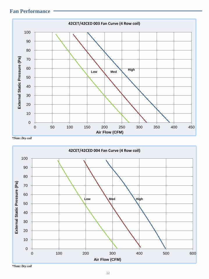
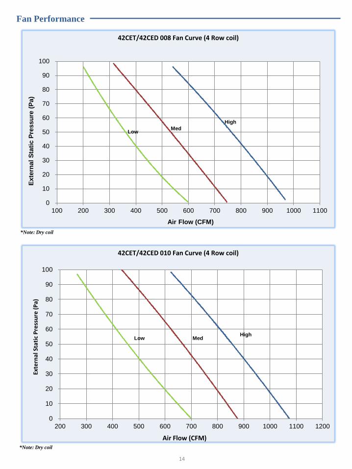
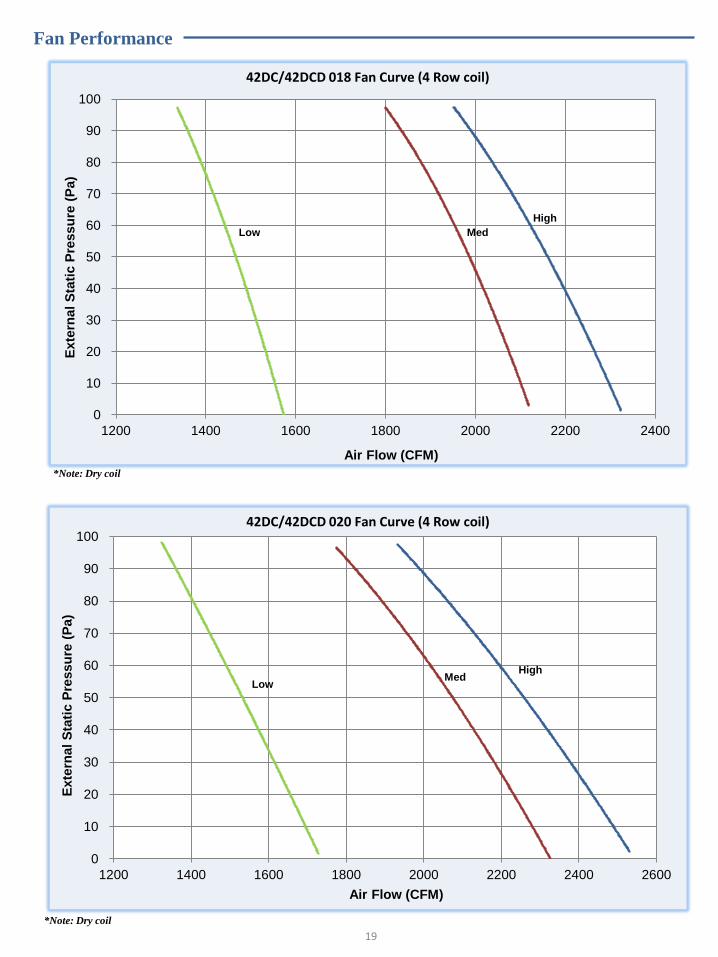
Fan Performance
12
42CET/42CED 003 Fan Curve (4 Row coil)
0
10
20
30
40
50
60
70
80
90
100
0 50 100 150 200 250 300 350 400 450
Exte
rnal
Sta
tic P
ressu
re (
Pa)
Air Flow (CFM)
High Med Low
*Note: Dry coil
42CET/42CED 004 Fan Curve (4 Row coil)
0
10
20
30
40
50
60
70
80
90
100
0 100 200 300 400 500 600
Exte
rna
l S
tati
c P
ressu
re (
Pa)
Air Flow (CFM)
High Med Low
*Note: Dry coil
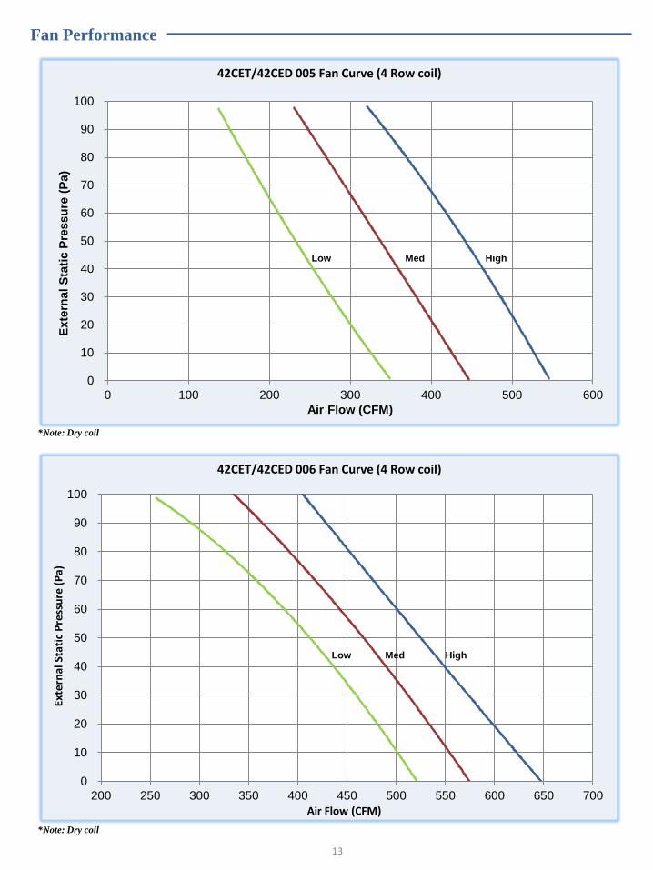
Fan Performance
42CET/42CED 006 Fan Curve (4 Row coil)
0
10
20
30
40
50
60
70
80
90
100
200 250 300 350 400 450 500 550 600 650 700
Exte
rnal
Sta
tic
Pre
ssu
re (
Pa)
Air Flow (CFM)
High Med Low
13
42CET/42CED 005 Fan Curve (4 Row coil)
0
10
20
30
40
50
60
70
80
90
100
0 100 200 300 400 500 600
Exte
rna
l S
tati
c P
ressu
re (
Pa)
Air Flow (CFM)
High Med Low
*Note: Dry coil
*Note: Dry coil
Fan Performance
42CET/42CED 008 Fan Curve (4 Row coil)
0
10
20
30
40
50
60
70
80
90
100
100 200 300 400 500 600 700 800 900 1000 1100
Exte
rnal
Sta
tic P
ressu
re (
Pa)
Air Flow (CFM)
High
Med Low
42CET/42CED 010 Fan Curve (4 Row coil)
0
10
20
30
40
50
60
70
80
90
100
200 300 400 500 600 700 800 900 1000 1100 1200
Exte
rnal
Sta
tic
Pre
ssu
re (
Pa)
Air Flow (CFM)
High Med Low
14
*Note: Dry coil
*Note: Dry coil
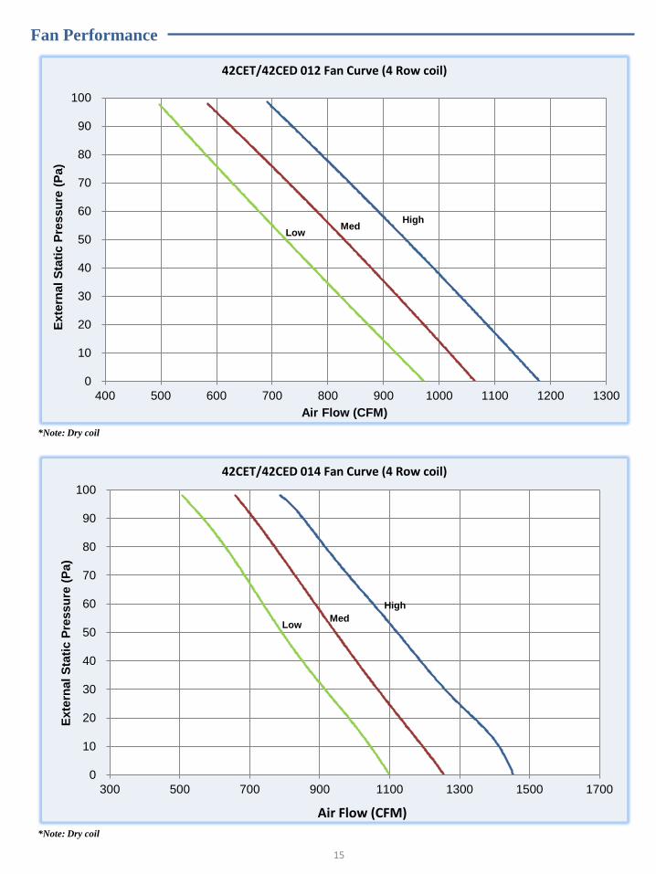
Fan Performance
42CET/42CED 012 Fan Curve (4 Row coil)
0
10
20
30
40
50
60
70
80
90
100
400 500 600 700 800 900 1000 1100 1200 1300
Exte
rnal
Sta
tic P
ressu
re (
Pa)
Air Flow (CFM)
High Med
Low
42CET/42CED 014 Fan Curve (4 Row coil)
0
10
20
30
40
50
60
70
80
90
100
300 500 700 900 1100 1300 1500 1700
Exte
rnal
Sta
tic P
ressu
re (
Pa)
Air Flow (CFM)
High
Med Low
15
*Note: Dry coil
*Note: Dry coil

Fan Performance
42DC/42DCD 006 Fan Curve (4 Row coil)
10
20
30
40
50
60
70
80
90
100
300 400 500 600 700 800 900 1000
Exte
rnal
Sta
tic P
ressu
re (
Pa)
Air Flow (CFM)
High
Med Low
16
42DC/42DCD 008 Fan Curve (4 Row coil)
10
20
30
40
50
60
70
80
90
100
300 400 500 600 700 800 900 1000
Exte
rnal
Sta
tic P
ressu
re (
Pa)
Air Flow (CFM)
High Med
Low
*Note: Dry coil
*Note: Dry coil
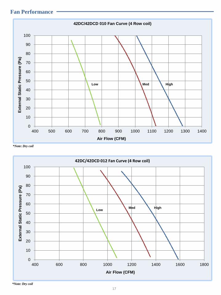
Fan Performance
42DC/42DCD 010 Fan Curve (4 Row coil)
0
10
20
30
40
50
60
70
80
90
100
400 500 600 700 800 900 1000 1100 1200 1300 1400
Exte
rnal
Sta
tic P
ressu
re (
Pa)
Air Flow (CFM)
High Med Low
42DC/42DCD 012 Fan Curve (4 Row coil)
0
10
20
30
40
50
60
70
80
90
100
400 600 800 1000 1200 1400 1600 1800
Exte
rnal
Sta
tic P
ressu
re (
Pa)
Air Flow (CFM)
High Med Low
17
*Note: Dry coil
*Note: Dry coil
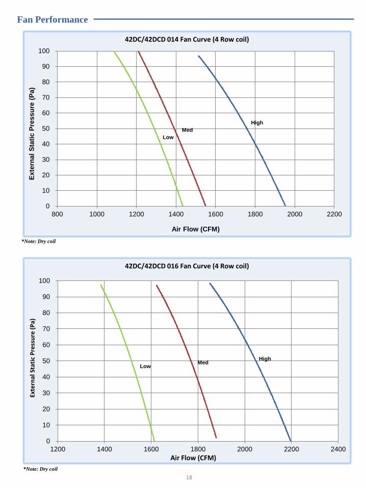
Fan Performance
42DC/42DCD 014 Fan Curve (4 Row coil)
0
10
20
30
40
50
60
70
80
90
100
800 1000 1200 1400 1600 1800 2000 2200
Exte
rnal
Sta
tic P
ressu
re (
Pa)
Air Flow (CFM)
High
Med
Low
18
*Note: Dry coil
42DC/42DCD 016 Fan Curve (4 Row coil)
0
10
20
30
40
50
60
70
80
90
100
1200 1400 1600 1800 2000 2200 2400
Exte
rnal
Sta
tic
Pre
ssu
re (
Pa)
Air Flow (CFM)
High Med
Low
*Note: Dry coil
Fan Performance
42DC/42DCD 020 Fan Curve (4 Row coil)
0
10
20
30
40
50
60
70
80
90
100
1200 1400 1600 1800 2000 2200 2400 2600
Exte
rnal
Sta
tic P
ressu
re (
Pa)
Air Flow (CFM)
High Med
Low
19
*Note: Dry coil
42DC/42DCD 018 Fan Curve (4 Row coil)
0
10
20
30
40
50
60
70
80
90
100
1200 1400 1600 1800 2000 2200 2400
Exte
rnal
Sta
tic P
ressu
re (
Pa)
Air Flow (CFM)
High
Med Low
*Note: Dry coil
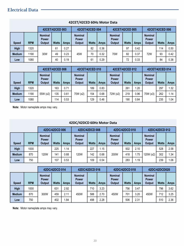
Electrical Data
42CET/42CED 60Hz Motor Data
42CET/42CED 003 42CET/42CED 004 42CET/42CED 005 42CET/42CED 006
Speed RPM
Nominal
Power
Output Watts Amps
Nominal
Power
Output Watts Amps
Nominal
Power
Output Watts Amps
Nominal
Power
Output Watts Amps
High 1320
30W
61 0.27
45W
82 0.36
70W
97 0.42
72W
114 0.50
Medium 1190 49 0.23 70 0.32 82 0.37 93 0.42
Low 1080 40 0.19 61 0.29 72 0.33 84 0.38
42CET/42CED 008 42CET/42CED 010 42CET/42CED 012 42CET/42CED 014
Speed RPM
Nominal
Power
Output Watts Amps
Nominal
Power
Output Watts Amps
Nominal
Power
Output Watts Amps
Nominal
Power
Output Watts Amps
High 1320
55W (x2)
163 0.71
70W (x2)
189 0.83
72W (x2)
261 1.20
70W (x3)
297 1.32
Medium 1190 135 0.61 154 0.68 219 0.96 262 1.14
Low 1080 114 0.53 129 0.46 190 0.84 235 1.04
42DC/42DCD 60Hz Motor Data
42DC/42DCD 006 42DC/42DCD 008 42DC/42DCD 010 42DC/42DCD 012
Speed RPM
Nominal
Power
Output Watts Amps
Nominal
Power
Output Watts Amps
Nominal
Power
Output Watts Amps
Nominal
Power
Output Watts Amps
High 1000
120W
225 1.14
120W
227 1.15
200W
502 2.10
120W (x2)
528 2.58
Medium 870 141 0.68 142 0.68 418 1.75 302 1.34
Low 750 107 0.53 109 0.54 283 1.19 239 1.06
42DC/42DCD 014 42DC/42DCD 016 42DC/42DCD 018 42DC/42DCD020
Speed RPM
Nominal
Power
Output Watts Amps
Nominal
Power
Output Watts Amps
Nominal
Power
Output Watts Amps
Nominal
Power
Output Watts Amps
High 1000
300W
631 2.92
450W
710 3.23
450W
756 3.47
450W
796 3.62
Medium 870 459 2.11 588 2.70 701 3.20 712 3.25
Low 750 402 1.84 498 2.28 506 2.31 510 2.36
Note: Motor nameplate amps may vary.
20
Note: Motor nameplate amps may vary.
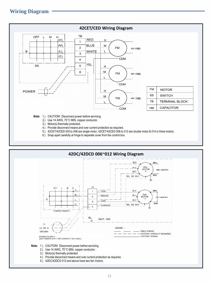
Wiring Diagram
42CET/CED Wiring Diagram
42DC/42DCD 006~012 Wiring Diagram
Note: 1.) CAUTION! Disconnect power before servicing.
2.) Use 14 AWG, 75°C MIN, copper conductor.
3.) Motor(s) thermally protected.
4.) Provide disconnect means and over current protection as required.
5.) 42CET/42CED 003 to 006 are single motor, 42CET/42CED 008 to 012 are double motor & 014 is three motors.
6.) Snap apart carefully at hinge to separate cover from the control box.
Note: 1.) CAUTION! Disconnect power before servicing.
2.) Use 14 AWG, 75°C MIN, copper conductor.
3.) Motor(s) thermally protected.
4.) Provide disconnect means and over current protection as required.
5.) 42DC/42DCD 012 and above have two fan motors.
21

Wiring Diagram
42DC/42DCD 014 ~ 020 Wiring Diagram
MODEL FAN MOTOR SPEED USED / COLOR
HIGH MEDIUM LOW UNUSED
42DC/42DCD 014 RED BROWN ORANGE YELLOW
42DC/42DCD 016 YELLOW BROWN ORANGE RED
42DC/42DCD 018 RED YELLOW ORANGE BROWN
42DC/42DCD 020 RED YELLOW ORANGE BROWN
Note: 1.) CAUTION: Disconnect power before servicing.
2.) Use 14 AWG, 75°C MIN, copper conductor.
3.) Motor(s) thermally protected.
4.) Provide disconnect means & over current protection as required.
5.) Unit 42DC/42DCD 014 and above have 2 fan motors.
22

Wiring Diagram With Heater
23
42CET/CED 003~012 & 42DC/DCD 006~012
42CET/CED 014 & 42DC/DCD 014~020
42DC/DCD 0144
42DC/DCD 0164 42DC/DCD 0184
42DC/DCD 0204

Electrical Heater Option
42C/42D WITH ELECTRICAL HEATER DATA
Model no Product Name Nominal size Heating kW Power Supply
42CED003H--30125
42CED &
42CET
003 1.2
230V-1PH-60Hz
42CED004H--30125 004 1.5
42CED005H--30125 005 1.8
42CED006H--30125 006 2.2
42CED008H--30125 008 2.4
42CED010H--30125 010 3
42CED012H--30125 012 3.6
42CED014H--30125 014 4.4
42DCD006H1-32125
42DCD &
42 DC
006 1.5
230V-1PH-60Hz
42DCD008H2-32125 008 2
42DCD010H3-32125 010 3
42DCD012H3-32125 012 3
42DCD012H4-32125 012 4
42DCD014H4-32125 014 4
42DCD014H5-32125 014 5
42DCD016H4-32125 016 4
42DCD016H5-32125 016 5
42DCD018H5-32125 018 5
42DCD018H6-32125 018 6
42DCD020H5-32125 020 5
42DCD020H6-32125 020 6
Note:
42DC/42DCD size 012 to size 020 are offered with 2 sets of heating kW
SPECIFICATIONS
Product Name Electric heater specifications
42CED
Fin type : Aluminum Construction: PTC type electric heater. Heater Mounting: Bracket with PPS material to hold on both sides of the heater.
Wires: Heater wires are protected with PPS material and pre-wires to the heater.
Over temperature cut off switch as a protection device.
42DCD
Fin type : Stainless Steel SUS304 Construction: Continuous spiral stainless steel fins SUS304 brazed to 8 mm diameter steel sheathed tubular element diameter over fin 28.5mm & fin pitch 5mm. Heater mounting : Mounting holes: 22mm diameter Wires: Heater wires are fully insulated with fiberglass & pre-wires to the heater.
Over temperature cut off switch as a protection device
24
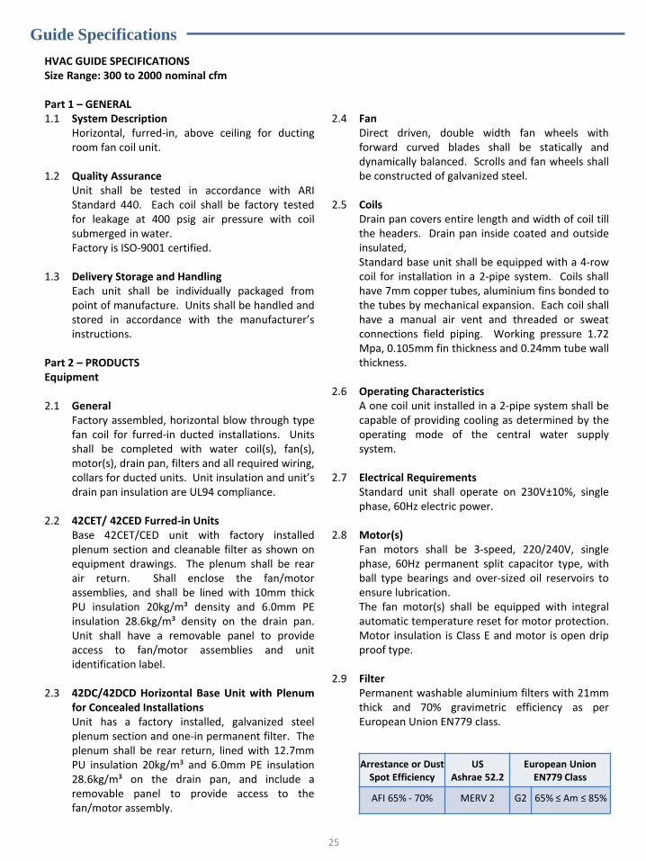
Guide Specifications
HVAC GUIDE SPECIFICATIONS Size Range: 300 to 2000 nominal cfm Part 1 – GENERAL 1.1 System Description Horizontal, furred-in, above ceiling for ducting
room fan coil unit. 1.2 Quality Assurance Unit shall be tested in accordance with ARI
Standard 440. Each coil shall be factory tested for leakage at 400 psig air pressure with coil submerged in water.
Factory is ISO-9001 certified. 1.3 Delivery Storage and Handling Each unit shall be individually packaged from
point of manufacture. Units shall be handled and stored in accordance with the manufacturer’s instructions.
Part 2 – PRODUCTS Equipment 2.1 General Factory assembled, horizontal blow through type
fan coil for furred-in ducted installations. Units shall be completed with water coil(s), fan(s), motor(s), drain pan, filters and all required wiring, collars for ducted units. Unit insulation and unit’s drain pan insulation are UL94 compliance.
2.2 42CET/ 42CED Furred-in Units Base 42CET/CED unit with factory installed
plenum section and cleanable filter as shown on equipment drawings. The plenum shall be rear air return. Shall enclose the fan/motor assemblies, and shall be lined with 10mm thick PU insulation 20kg/m³ density and 6.0mm PE insulation 28.6kg/m³ density on the drain pan. Unit shall have a removable panel to provide access to fan/motor assemblies and unit identification label.
2.3 42DC/42DCD Horizontal Base Unit with Plenum
for Concealed Installations Unit has a factory installed, galvanized steel
plenum section and one-in permanent filter. The plenum shall be rear return, lined with 12.7mm PU insulation 20kg/m³ and 6.0mm PE insulation 28.6kg/m³ on the drain pan, and include a removable panel to provide access to the fan/motor assembly.
2.4 Fan Direct driven, double width fan wheels with
forward curved blades shall be statically and dynamically balanced. Scrolls and fan wheels shall be constructed of galvanized steel.
2.5 Coils Drain pan covers entire length and width of coil till
the headers. Drain pan inside coated and outside insulated,
Standard base unit shall be equipped with a 4-row coil for installation in a 2-pipe system. Coils shall have 7mm copper tubes, aluminium fins bonded to the tubes by mechanical expansion. Each coil shall have a manual air vent and threaded or sweat connections field piping. Working pressure 1.72 Mpa, 0.105mm fin thickness and 0.24mm tube wall thickness.
2.6 Operating Characteristics A one coil unit installed in a 2-pipe system shall be
capable of providing cooling as determined by the operating mode of the central water supply system.
2.7 Electrical Requirements Standard unit shall operate on 230V±10%, single
phase, 60Hz electric power. 2.8 Motor(s) Fan motors shall be 3-speed, 220/240V, single
phase, 60Hz permanent split capacitor type, with ball type bearings and over-sized oil reservoirs to ensure lubrication.
The fan motor(s) shall be equipped with integral automatic temperature reset for motor protection. Motor insulation is Class E and motor is open drip proof type.
2.9 Filter Permanent washable aluminium filters with 21mm
thick and 70% gravimetric efficiency as per European Union EN779 class.
25
Arrestance or Dust Spot Efficiency
US Ashrae 52.2
European Union EN779 Class
AFI 65% - 70% MERV 2 G2 65% ≤ Am ≤ 85%
Optional
26
Drain Pan
100mm extended drain pan, galvanized or stainless material is available.
Sandwich Drain Pan
Two layers of galvanized drain pans with polyurethane insulation in between.
Insulation
Fired rated class 0 insulation.
Casing
Anti-corrosion powder coated panels. Impressive looks.
Double Skin Panel
Anti-corrosion powder coated external panels with in between polyurethane insulation in between.
Filter
21mm synthetic media filter. Contact factory if special filter is required.
Motors
Class F insulation motor provides reliable operation and suits harder applications. Fan coil units
equipped with ECM motor and controller are available as an option.

Manufacturer reserves the right to discontinue, or change at anytime, specifications or designs without notice and without incurring obligations.
42CD-J14-3PD
Carrier International Sdn. Bhd. (3385-T) Lot 4, Jalan P/6, 43650 Bandar Baru Bangi,
Selangor Darul Ehsan, Malaysia. Tel: 03-8913 7600