Embed Size (px)
Citation preview
4. CREEP ESTIMATIONS IN STRUCTURAL ANALYSIS
In Chapters2 and3 we introduced creep constitutive and damage evolution equations for themodeling of creep in engineering materials. The objective of Chapt.4 is the application ofcreep constitutive models to structural analysis. In Sect.4.1 we start with the discussion ofbasic steps in modeling of creep in structures with the application of finite element method(FEM). The advantages of FEM application and creep analysisprocedures in a commercialFEM-based software with conventional and user-defined constitutive models are highlighted.Section4.2is devoted to the introduction of benchmark problem conceptin the frames of struc-tural mechanics, description of its main purposes in creep mechanics and verification steps fora reliability assessment. As examples, two benchmark problems of creep-damage mechanicswhich can be solved by approximate numerical methods are presented. The reference solu-tions are compared with the finite element solutions by ANSYSand ABAQUS finite elementcodes with user-defined creep model subroutines. To discussthe applicability of the devel-oped techniques to real engineering problems two examples of numerical life-time assessmentwith application of creep-damage models for initial-boundary value problems are presented inSects4.3 and4.4. The purpose of Sect.4.3 is the numerical creep behavior modeling of theT-piece pipe weldment made of the 9Cr-1Mo-V-Nb (ASTM P91) heat-resistant steel. The ini-tially transversally-isotropic creep-damage model developed in Sect.2.2.1is incorporated in thecommercial FEM-based CAE-software ANSYS. The numerical analysis results of the weldedstructure qualitatively agree with available experimental observations and confirm the facts ofvarious creep and damage material properties in longitudinal and transversal directions of awelding seam. Finally, in Sect.4.4 an example of life-time assessment for the housing of aquick stop valve usually installed on steam turbines is presented. Long-term behavior of thiscomponents under approximately in-service loading conditions (constant internal pressure andconstant temperature) is simulated by the FEM. The results show that the developed in Chapt.3constitutive model is capable to reproduce specific features of creep and damage processes inengineering structures during the long-term thermal exposure.
4.1 Application of FEM to creep-damage analysis
The aim of creep modeling is to reflect basic features of creepin engineering structures includ-ing the development of inelastic deformations, relaxationand redistribution of stresses as wellas the local reduction of material strength. A model should be able to account for material de-terioration processes in order to predict long-term structural behavior, to estimate the in-servicelife-time of a component and to analyze critical zones of failure caused by creep. Structuralanalysis under creep conditions usually requires the following steps, proposed in [147, 152]:

64 4. Creep estimations in structural analysis
1. Assumptions must be made with regard to the geometry of thestructure, types of loadingand heating as well as kinematical constraints.
2. A suitable structural mechanics model (e.g. three-dimensional solids, beams, rods, platesand shells) must be applied based on the assumptions concerning kinematics of deforma-tions, types of internal forces (moments) and related balance equations.
3. A reliable constitutive model must be formulated to reflect time dependent creep defor-mations and processes accompanying creep like hardening/recovery and damage.
4. A mathematical model of the structural behavior (initial-boundary value problem) must beformulated including the material independent equations,constitutive (evolution) equa-tions as well as initial and boundary conditions.
5. Numerical solution procedures (e.g. the Ritz method, theGalerkin method, the finiteelement method) to solve non-linear initial-boundary value problems must be developed.
6. The verification of the applied models must be performed including the structural me-chanics model, the constitutive model, the mathematical model as well as the numericalmethods and algorithms.
For the numerical solution the direct variational methods,e.g. the Ritz method, the Galerkinmethod and the finite element method (FEM), are usually applied. In recent years the FEMhas become the widely accepted tool for structural analysis. The advantage of the FEM is thepossibility to model and analyze engineering structures with complex geometries, various typesof loadings and boundary conditions. General purpose finiteelement codes ABAQUS, AN-SYS, NASTRAN, COSMOS, MARC, ADINA, etc. were developed to solve various problemsin solid mechanics. In application to the creep analysis oneshould take into account that ageneral purpose constitutive equation which allows to reflect the whole set of creep and dam-age processes in structural materials over a wide range of loading and temperature conditionsis not available at present. Therefore, a specific constitutive model with selected internal statevariables, special types of stress and temperature functions as well as material constants identi-fied from available experimental data should be incorporated into the commercial finite elementcode by writing a user-defined material subroutine. The examples of manuals for the proceduresof user-defined subroutines implementation into the commercial FEM-based software ANSYSand ABAQUS can be found in [3, 22]. The ABAQUS and ANSYS finite element codes areapplied to the numerical analysis of creep in structures, e.g. [66, 140, 152, 170, 181, 182].
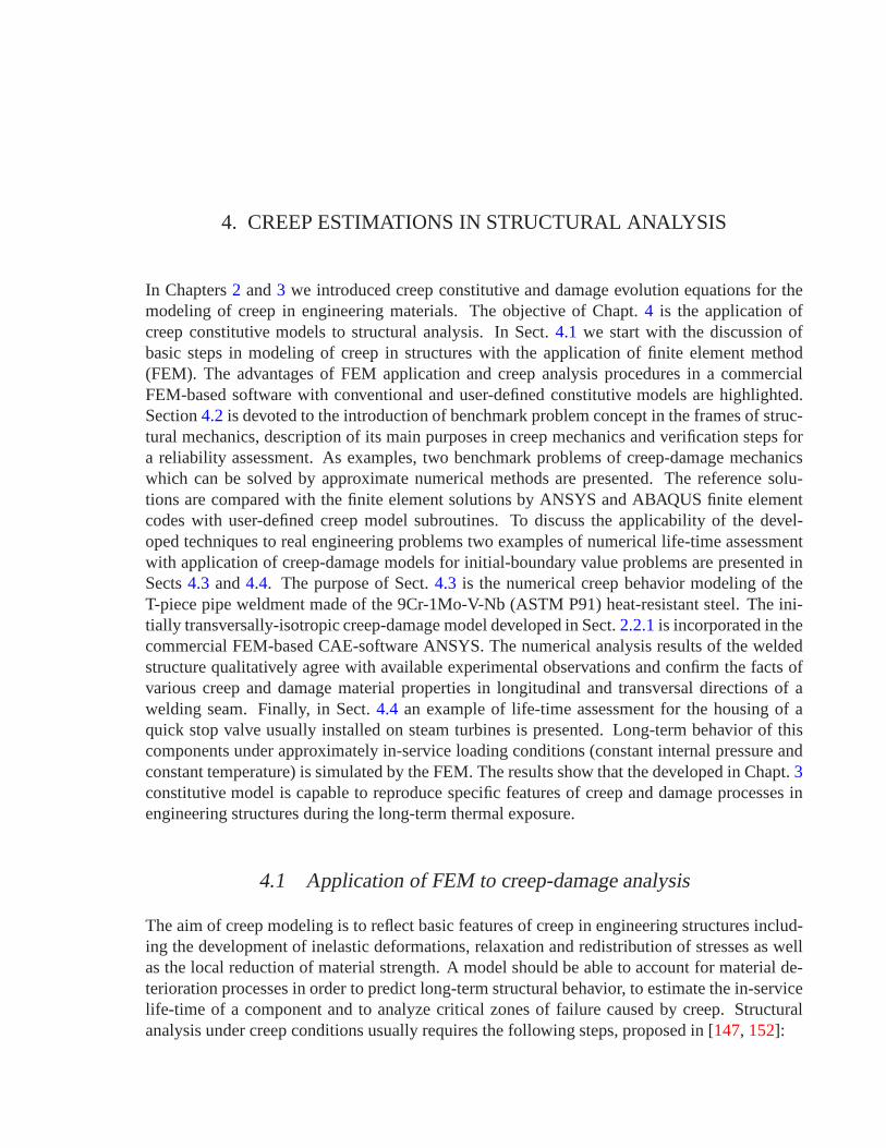
The standard features of the commercial FEM-based software(e.g., ANSYS and ABAQUS)includes only conventional creep models, refer to [1, 20]. Strain hardening, time hardening, ex-ponential, Graham and Blackburn models, etc. are proposed for the primary creep stage andGarofalo, exponential and Norton models, etc. are proposedfor the secondary creep stage. Us-ing standard creep models incorporated into FEM-based software it is impossible to model thetertiary creep stage accompanied with damage accumulationprocess and fracture, see Fig.4.1.In order to consider damage processes the user-defined subroutines are developed and imple-mented. The subroutines serve to utilize constitutive and evolution equations with damage statevariables, see Fig.4.1. In addition, they allow the postprocessing of damage, i.e.the creation ofcontour plots visualizing damage distributions.

4.1. Application of FEM to creep-damage analysis 65
Preprocessor,t := 0
Computing theStiffness Matrixand Force Vector
[KKK]t, [ fff ]t
Solving the Systemof AlgebraicEquations
[KKK]Tt [uuu]t = [ fff ]t
ConventionalCreep Laws
εεεcr =3
2
g(σvM)
σvM
sss
SolutionOutput
for Postprocessor
Postprocessor
Creep Laws
εεεcrt = gggε(σσσt, σσσbt
, ωωωt, T),σσσbt
= gggh(σσσt, σσσbt, ωωωt, T),
ωωωt = gggω(σσσt, σσσbt, ωωωt, T)
Updateεεεcr
t+∆t, σσσbt+∆t, ωωωt+∆t,
t := t + ∆t
ωωωt < ωωω∗
?
yes
yes
no
no
User-DefinedCreep Laws
User-definedCREEP Subroutine
is specified?
Fig. 4.1:Creep analysis procedures in a commercial FEM software withconventional creep laws andwith user-defined creep-damage models, after [148].

66 4. Creep estimations in structural analysis
4.2 Numerical benchmarks for creep-damage modeling
The concept of benchmarks is widely used in computational engineering mechanics and partic-ularly in creep-damage mechanics. Several benchmark problems based on the different creepconstitutive models are presented in [12, 16, 28, 29, 152, 2]. To consider both the creep and thedamage processes, a specific constitutive model with selected internal state variables, specialtypes of stress and temperature functions as well as material constants identified from avail-able experimental data should be incorporated into the commercial FE-code by writing a user-defined material subroutine, see e.g. [3, 22]. Thus benchmark problems are needed to verifythose developed subroutines. For these problems numericalor analytical reference solutionsare usually obtained. To conclude about the fact that the subroutines are correctly coded andimplemented, results of finite element computations must becompared with reference solutionsof benchmark problems.
4.2.1 Purposes and applications of benchmarks
An important question in the creep analysis is that on reliability of the applied models, numer-ical methods and obtained results. To assess the reliability of the developed subroutine as wellas the accuracy of the results with respect to the mesh density, type of finite element, the timestep, and the iteration methods, numerical benchmark problems are required. In [147, 152] thefollowing verification steps are proposed for the reliability assessment:
• Verification of developed finite element subroutines.To assess that the subroutines are cor-rectly coded and implemented, results of finite element computations must be comparedwith reference solutions of benchmark problems. Several benchmark problems have beenproposed in [29] based on an in-house finite element code. Below we recall closed formsolutions of steady-state creep in elementary structures,well-known in the creep mechan-ics literature. To extend these solutions to the primary andtertiary creep ranges we applythe Ritz and the time step methods. The advantage of these problems is the possibility toobtain reference solutions without a finite element discretization. Furthermore, they allowto verify finite element subroutines over a wide range of finite element types includingbeam, shell and solid type elements.
• Verification of applied numerical methods.Here the problems of the suitable finite ele-ment type, the mesh density, the time step size and the time step control must be analyzed.They are of particular importance in creep damage related simulations. Below these prob-lems are discussed based on numerical tests and by comparison with reference solutions.
• Verification of constitutive and structural mechanics models. This step requires creep testsof model structural components and the corresponding numerical analysis by the use ofthe developed techniques. Examples of recent experimentalstudies of creep in structuresinclude beams [40, 152], transversely loaded plates [112, 146, 152], thin-walled tubesunder internal pressure [115, 117], pressure vessels [66, 68], circumferentially notchedbars [87]. Let us note that the experimental data for model structures are usually lim-ited to short-term creep tests. The finite element codes and subroutines are designed

4.2. Numerical benchmarks for creep-damage modeling 67
to analyze real engineering structures. Therefore long term analysis of several typicalstructures should be performed and the results should be compared with data collectedfrom engineering practice of power and petrochemical plants. Below the examples of thecreep finite element analysis for the typical components of power-generation plants arediscussed.
4.2.2 Simply supported beam
To formulate a benchmark problem using the creep-damage analysis of the simply supportedaluminium alloy beam loaded by a distributed forceq [152] it is necessary to compare theresults obtained by the Ritz method with those of ABAQUS and ANSYS finite element codesincorporating the Kachanov-Rabotnov phenomenological creep-damege model [121]:
εεεcr =3
2
a σvMn
(1 − ω)msss
σvM
, ω = b[α σT + (1 − α)σvM]k
(1 − ω)lwith σT =
1
2(σI + |σI |) (4.2.1)
In this notationεεεcr is the creep rate tensor,sss is the stress deviator,σvM is the von Mises equiv-alent stress,σT is the maximum tensile stress,σI is the first principal stress,ω is the damageparameter andα represents the weighting factor of a material.a = 1.35 ··· 10−39 [MPa−n/h],b = 3.029 ··· 10−35 [MPa−k/h], n = 14.37,m = 10, k = 12.895,l = 12.5 andα = 0 are mate-rial constants after [116] for the aluminium alloy BS 1472 at 150±0.5◦C corresponding to themodel (4.2.1). Figure4.2shows the good agreement of the time variations of maximum deflec-tion and the normal stress obtained by the Ritz method and theFEM with the exception of thecalculations based on the ANSYS finite element code using element type SHELL43, see [21].
4.2.3 Pressurized thick cylinder
We incorporated the following creep constitutive equation(4.2.2) into the ABAQUS finite ele-ment code by the means of user-defined material subroutines
εεεcr =3
2
ε0
σ0
[
1 +
(
σvM
σ0
)n−1]
sss, ε0 ≡ aσ0 (4.2.2)
with the material constantsε0 = 2.5 ··· 10−7 1/h, σ0 = 100 MPa,n = 12 corresponding to9Cr1MoVNb steel at 600◦C obtained from the creep tests for both the linear and the powerlaw ranges data after [108, 110].
A reference solution of steady-state creep according to Eq.(4.2.2) for a thick cylinder sec-tion loaded by internal pressurep is obtained by means of two numerical procedures includingthe numerical integration and finding the root of a non-linear algebraic equation using Mathcadpackage (for the details refer to [12]). The results obtained by the presented in [12] approximatemethod are applied to verify the finite element solution. Thesteady-state creep problem of thethick cylinder in the power law creep range is the standard benchmark. Thus the geometricaldata and the finite element model are assumed as given in the benchmark manual [2].
Figure4.3 illustrates a good agreement of the solutions based on the ABAQUS finite codeand the approximate numerical solutions for different values of the normalized pressurep inboth the linear and the power law ranges.

68 4. Creep estimations in structural analysis
a)0 10000 20000 30000 40000 50000 60000 70000 80000
5
10
15
20
25
30
t, h
wm
ax,m
m
Ritz Method
ABAQUS, S4R5
ABAQUS, CPS4R
ANSYS, SHELL 43
ANSYS, PLANE 42
b)0 10000 20000 30000 40000 50000 60000 70000 80000
80
100
120
140
160
180
200
220
240
t, h
σ max
,MP
a
Ritz Method
ABAQUS, S4R5
ABAQUS, CPS4R
ANSYS, SHELL 43
ANSYS, PLANE 42
l =100 mm, b=30 mm, h=80 mm
q=2 N/mm2
wmax σmaxl
b
h
Fig. 4.2:Creep-damage analysis results vs. time in the bottom layer of the middle cross-section of asimply supported beam obtained by the Ritz method and the finite element codes using shelland plane stress type finite elements: a) maximum deflection,b) normal stress

4.2. Numerical benchmarks for creep-damage modeling 69
a)
20
30
40
50
60
70
80
90
100
110
120
130
140
150
25 30 35 40 45 50
r, mm
σϕ, M
Pa
Elastic distributionSteady-state creep distributionABAQUS/FEA solutions
b)
-100
-90
-80
-70
-60
-50
-40
-30
-20
-10
0
25 30 35 40 45 50r, mm
σ r, M
Pa
p = 90 MPap = 70 MPap = 40 MPa
p
z
r
ra
rb
Mesh: 10 elements,type CAX8R (8-node)
Geometrical parameters:ra = 25.4 mm, rb = 50.8 mm
Fig. 4.3:Stresses vs. radial coordinate for a pressurized thick cylinder under the steady-state creep con-ditions computed by an approximate numerical method and theABAQUS finite element code:a) hoop stress, b) radial stress
70 4. Creep estimations in structural analysis
4.3 Anisotropic creep of a pressurized T-piece pipe weldment
This section is devoted to the practical application of the initially anisotropic model presentedin Sect.2.2.1and research work [80] to the long-term strength analysis in creep conditions ofa T-piece pipe weldment made of the 9Cr-1Mo-V-Nb (ASTM P91) heat-resistant steel. Theconstitutive model and appropriate creep parameters were based on the experimental creep andrupture data [95] of multi-pass weldmen considering the non-uniformity of the microstructurein the heat affected zone, in the base material and in the weldmetal of welding joint. For thepurpose of adequate creep behavior numerical modeling of the welding seam, the transversally-isotropic creep-damage model have been incorporated in thecommercial FEM-based CAE-software ANSYS. The model takes into account various creep and damage material propertiesin longitudinal and transversal directions of a welding seam. The performed numerical calcula-tions of the welded structure qualitatively agree with experimental data by MPA Stuttgart [104]and confirm the facts of rupture in corresponding zones of thewelding joint.
4.3.1 Formulation of structural model
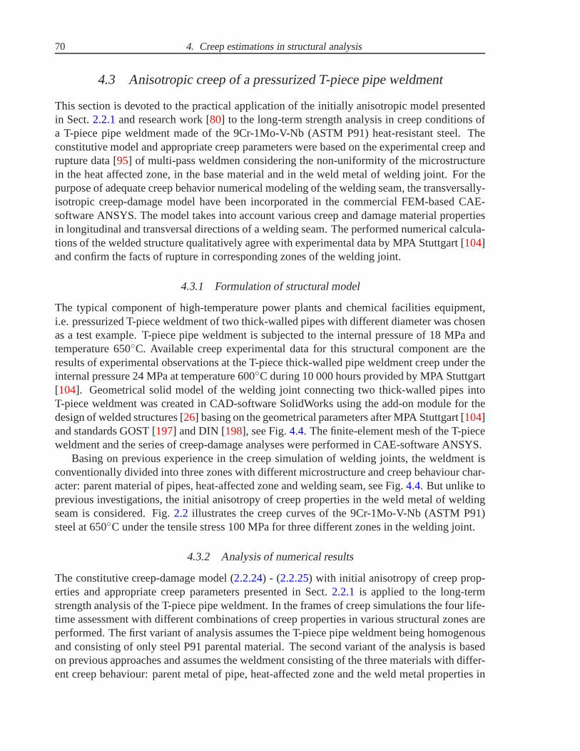
The typical component of high-temperature power plants andchemical facilities equipment,i.e. pressurized T-piece weldment of two thick-walled pipes with different diameter was chosenas a test example. T-piece pipe weldment is subjected to the internal pressure of 18 MPa andtemperature 650◦C. Available creep experimental data for this structural component are theresults of experimental observations at the T-piece thick-walled pipe weldment creep under theinternal pressure 24 MPa at temperature 600◦C during 10 000 hours provided by MPA Stuttgart[104]. Geometrical solid model of the welding joint connecting two thick-walled pipes intoT-piece weldment was created in CAD-software SolidWorks using the add-on module for thedesign of welded structures [26] basing on the geometrical parameters after MPA Stuttgart [104]and standards GOST [197] and DIN [198], see Fig.4.4. The finite-element mesh of the T-pieceweldment and the series of creep-damage analyses were performed in CAE-software ANSYS.
Basing on previous experience in the creep simulation of welding joints, the weldment isconventionally divided into three zones with different microstructure and creep behaviour char-acter: parent material of pipes, heat-affected zone and welding seam, see Fig.4.4. But unlike toprevious investigations, the initial anisotropy of creep properties in the weld metal of weldingseam is considered. Fig.2.2 illustrates the creep curves of the 9Cr-1Mo-V-Nb (ASTM P91)steel at 650◦C under the tensile stress 100 MPa for three different zones in the welding joint.
4.3.2 Analysis of numerical results
The constitutive creep-damage model (2.2.24) - (2.2.25) with initial anisotropy of creep prop-erties and appropriate creep parameters presented in Sect.2.2.1 is applied to the long-termstrength analysis of the T-piece pipe weldment. In the frames of creep simulations the four life-time assessment with different combinations of creep properties in various structural zones areperformed. The first variant of analysis assumes the T-piecepipe weldment being homogenousand consisting of only steel P91 parental material. The second variant of the analysis is basedon previous approaches and assumes the weldment consistingof the three materials with differ-ent creep behaviour: parent metal of pipe, heat-affected zone and the weld metal properties in

4.3. Anisotropic creep of a pressurized T-piece pipe weldment 71
110070
9595
38273
50
380
490
a)
b)
c)
pressurecover
mainpipe
nozzle pipe
nozzle pipe
HAZ
weld metal
Fig. 4.4:Exterior view, geometrical parameters (mm) and structure:a) experimental facility, after [104],b) solid geometry, c) finite-element model.
cracks(type III)
cracks(type III)
Fig. 4.5:Distribution of damage parameters values before the rupture: anisotropic parameterω1 in theweld metal and isotropic parameterω in other zones of T-piece pipe weldment.

72 4. Creep estimations in structural analysis
the plane of isotropy. And the last two variant of the analysis are similar to the previous ones,however the initial anisotropy of the weld metal creep properties is taken into account.
The creep simulations are performed by the FEM in CAE-software ANSYS till the mo-ment of rupture in each analysis case. And the obtained numerical results demonstrate thespecific qualitative tendencies in damage accumulation character as shown below. In the caseof homogenous material (parent pipe material) or non-uniform material with isotropic creepproperties of all three weldment zones, the failure caused by the damage accumulation occursonly in heat-affected zone, see Fig.4.5. Such character of failure corresponds to the longitudi-nal cracks type III due to classification of cracks in weldments presented on Fig.2.3and Table2.1. This type of cracks is proved by the experimental observation presented on Fig.4.6 andTable4.1 with circumferential cracks in the heat-affected zone (HAZ) having numbers 1 and4. In this case the time-to-rupture of the weldment is governed only by the creep propertiesof the heat-affected zone. The damage accumulation in the isotropic weld metal of weldingseam is practically missed, and the value of damage parameter is almost equal to zero. Such anumerical results of creep simulations qualitatively agree with similar investigation in the fieldof finite-element creep modeling of pressurized welded pipes, see e.g. [91].
Unlike to the previous two analysis cases with isotropic creep properties of materials, theresults of the analysis cases considering anisotropic properties of the welding seam show thesignificant accumulation of two damage parametersω1 andω2 in the weld metal, see Fig.4.7.The accumulation character of the damage parametersω1 andω2 shows the probable initia-tion of the reach-through longitudinal cracks and transversal cracks. Such character of failurecorresponds to cracks types I and II due to classification of cracks in weldments, illustrated onFig. 2.3and described in Table2.1. This type of cracks is proved by the experimental observa-tion presented on Fig.4.6 and Table4.1 with the reach-through axial cracks in the weld metalhaving numbers 3 and 5.
1
2
3
4
5
u, ϕ
rear
front
rightleft
butt strappressure
connection
Fig. 4.6:Damage situation in P91 T-piece weldment and welded vessel under internal pressure 24 MPaafter 10 000 hours of experimental observations at 650◦C, after [104].

4.3. Anisotropic creep of a pressurized T-piece pipe weldment 73
Table 4.1:Damage situation in P91 T-piece weldment and welded vessel under internal pressure 24 MPaafter 10 000 hours of experimental observations at 650◦C, after [104].
PositionCrackposition
Crack directionCrack centerat u, mm
Crack depth,mm
1 HAZ Circumferential 10 ca. 10
2 Weld metal Circumferential 150 —
3 Weld metal T-joint (axial) 220 Through wall
4 HAZ Circumferential 435 10
5 Weld metal T-joint (axial) 640 Through wall
a)
b)
crack (type I)
crack (type II)
Fig. 4.7:Distribution of damage parameters values in the weld metal before the rupture: a) along thewelding directionω1, b) transversely to the welding directionω2.

74 4. Creep estimations in structural analysis
The numerical results obtained with the assumption of anisotropic creep properties in theweld metal have more reliable agreement with the creep experimental observations for this t-piece pipe weldment, illustrated on Fig.4.6 and Table4.1, and others welded pipe structures[96]. Alongside with the cracks with types III and VI caused by the critical damage accumu-lation in the heat-affected zone (see Fig.4.5), the experimental studies [104] report that thereach-through longitudinal cracks with types I and II are initiated by the transversally-isotropicdamage parameters accumulation in the weld metal (see Fig.4.7).
The principal result of the research [80] presented in Sects2.2.1 and 4.3 is to show theability of the continuum mechanics approach application tocreep simulations of weldmentsconsidering non-uniformity of microstructure and anisotropic creep properties of weld metal.Consideration of transversely-isotropic creep properties of weld metal allows to predict the localzones of damage accumulation and probable cracks initiation with better qualitative accuracy.This assumption correlates with the experiments [104] obtained by MPA Stuttgart during the in-service observations for the similar structures. The obtained numerical results demonstrate thenecessity of the subsequent creep-rupture experiments forthe different weldment zones (parentmaterial, heat-affected zone and weld metal). The availability of the comprehensive creep-rupture experimental data will allow to simulate the long-term strength behaviour of weldmentsmore accurately under the in-service loading conditions.
4.4 Creep-damage analysis of power plant components
For the high-temperature components with complex geometry(e.g. pressure piping systems andvessels, rotors and turbine blades, casings of valves and turbines, etc.), where neither analyticalnor experimental reference stresses are available, the computer-based finite element analysis(FEA) is used, e.g. [30, 76, 96, 152]. The component is “broken down” into an aggregate offinite elements (FE) with prescribed properties. The computer analysis evaluates the responseof the component as a whole and enables the stresses and strains at any given point to be deter-mined. A detailed picture of the results distribution within the component is produced. In itssimplest form the FEA may only be applied to analyse the elastic stresses, but the knowledge ofthe creep properties of the material enables a long-term strength analysis or life-time assessmentto be performed.
4.4.1 Previous experience in FEA
The development of computational continuum damage mechanics (CDM) now allows FEA tobe performed using physically based constitutive equations to describe the material behavior.This enables the full time dependent behavior of a structureto be modeled, including, by the in-put of ductility values, the transition from generalized damage to discrete crack growth. Increas-ing speed and data storage capacity of computer workstations rapidly reduces the time requiredfor such computations. However, the procedure is critically dependent upon the availability ofvalidated multi-axial constitutive equations for deformation and damage over the mechanisticregimes encountered [89, 152].
Modern power-generation plants are required to provide high standards of reliability andavailability, which principally depends on the operating conditions, optimal structural design

4.4. Creep-damage analysis of power plant components 75
and the applied constructional materials. The reliabilityand safety of the whole power systemdepends greatly on the way in which the main power unit components such as the turbine, boilerand generator are operated. The operating conditions of those devices are usually very complexand involve many unsteady mechanical and thermal loads which in consequence determinethe stress states of the particular components. The durability of the steam turbine should beconsidered in terms of the durability of its main components, which can be divided into twomajor groups, mainly the shells (casings, valve housings) and rotating parts (rotors).
The thermal and mechanical loadings within the operation conditions usually lead to degra-dation of material owing to intensive interactions of many failure modes such as local plasticity,high temperature creep, damage, corrosion, fatigue and cracking. Interactions of main modesof degradation are complex in appropriate numerical modelling and difficult for the numericallybased life-time predictions. For instance, creep and damage can be intensified by the processof locally variable high thermal stresses during cycles of loading and unloading. Growing de-mands on safe, reliable and economic operation ask for a sufficient life-time prolongation ofthe critical power plant elements. A lot of numerical investigations by different laboratoriesbased on CDM and FEA presenting long-term strength analysesand life-time assessments ofhigh-temperature steam-turbine components were published recently, e.g. [38, 39, 98, 158].
In the framework of this dissertation several FEM-based life-time assessments of high-temperature power plant components were performed using the formulated in Sect.2 consti-tutive creep-damage models:
• The numerical investigations of long-term strength behaviour started with the applica-tion of conventional Kachanov-Rabotnov-Hayhurst creep-damage model [40, 89, 152] toisothermal creep-damage simulation [77]. As the component to be analysed the casingof a steam turbine reheat control valve was chosen. Such a component has to control thesteam flow into an intermediate pressure steam turbine. The investigation has proved thehigh efficiency of FEM-based life-time assessments with theapplication of conventionalCDM-based creep models.
• Within the frames of the research work [79] two conventional creep-damage models wereapplied to the isothermal simulation of the mechanical behaviour of a steam turbine ro-tor in its in-service conditions. These models were the isotropic Kachanov-Rabotnov-Hayhurst model [40, 89, 152] and the Murakami-Ohno [141, 142] model with damageinduced anisotropy presented in Sect.2.2.2. Numerical solutions of the initial-boundaryvalue problems have been obtained by FEM using solid axisymmetrical type finite el-ements. For the purpose of adequate long-term strength analysis both isotropic andanisotropic creep-damage models have been implemented in FE-code of the commer-cial CAE-software ANSYS. Obtained simulation results for asteam turbine rotor showthe significant sensitivity of life-time assessment to the type of material model.
• Thereafter, the conventional Kachanov-Rabotnov-Hayhurst creep-damage model [40, 89,152] was extended to the case of variable temperature and strainhardening consider-ation, as presented in Sect.2.1. A technique for the identification of material creepconstants based on the available family of experimental creep curves (see AppendixA)was presented in [114, 129]. The resulting non-isothermal model with the appropriate

76 4. Creep estimations in structural analysis
creep material parameters [113] were incorporated into the FE-code of the CAE-softwareABAQUS. It was applied to the long-term strength analysis ofa pressurized thick-walledpipe exposed to the non-uniform heating for the verificationpurposes and for the illus-tration of basic features of creep-damage character, referto [129]. Than the model wasapplied to the non-isothermal life-time assessments underin-service loading conditionsof such power plant components, as the casing of a steam turbine control-stop valve [114],the casing of a steam turbine bypass valve [130], housing of a high-pressure gas turbine[131], and the casing of a steam turbine quick-stop valve [132]. The obtained numeri-cal results confirmed the influence on non-uniform temperature field on the final stressand strain fields redistribution before the failure. However, the time-to-rupture values un-der the in-service loading conditions were overestimated,because the applied model issuitable only for the narrow range of the high stresses.
4.4.2 Steam turbine quick-stop valve
Finally, we must discuss several results of long-term analysis obtained by application of thenew creep-damage constitutive model developed in Chapt.3 to creep behaviour simulation ofa power plant component. As the component to be analysed the casing of a steam turbinequick-stop valve [54, 55, 56], illustrated on Fig.4.8, was chosen.
Application
If the steam turbine is tripped it is essential to have a fast and reliable quick stop function forprotection of the turbine. The steam turbine quick stop valve (VQS) is designed for this purpose[55]. A mechanical spring is used for the emergency shut-off. The closing time is typically lessthan 0.2 s for full stroke. On request shorter closing time isavailable. The emergency quickclose function achieves maximum protection for the steam turbine. The valves are equippedwith on-line exercise capability that demonstrates freedom of movement of tripping componentswithout affecting steam flow. The VQS valve is used together with the turbine flow control valve(VPC), as illustrated in Fig.4.8. The VPC valve is designed for regulating the steam flow fromstart-up to full load. As an option the VPC valve can be equipped with a quick closing function.The low total pressure drop over the valves improves the energy efficiency of the installation,thus improving the power production. Each valve is independently calculated and designedaccording to the relevant operational conditions.
Design features
The VQS and VPC valves design is of angle type and is based on the well proven design ofstop valve type VS. As far as, the drawings of the VQS valve casing were not accessible fromopened sources, it was decided to use the drawing of VS valve casing available from [56] andillustrated on Fig.4.8for the modeling of 3D solid geometry in the CAD-software SolidWorks.The VS valve casing [56], fully machined of forged CrMo low alloy steel or carbon steel,including X10CrMoVNb91 (F91) steel, is designed to minimize material stresses as well asto fit the requirements of the piping system with regard to material, pressure class and pipingconnections [54]. An even material distribution is essential to minimize the material stresses.

4.4. Creep-damage analysis of power plant components 77
By using the homogenous forged material, an accurate and controlled wall thickness, i.e. asmooth surface, is achieved. For severe operating conditions with large temperature variations,a continuous preheating of the valve inlet side is recommended. The VS valve is designed to beoperated by an actuator, and depending on the actuating force and project preference, any typeof actuator can be selected: pneumatic, electrohydraulic or electromechanical. The unbalancedconfiguration of VS valve casing with tight design providingleakage tightness according toANSI B16.104 Class V was selected, see Fig.4.8. The maximum capacity of the VQS valveis 7500 Kv or 8660 Cv, the maximum inlet pressure class corresponds to DIN-PN 640 (ANSI#4500), the maximum outlet pressure class corresponds to DIN-PN 250 (ANSI# 1500). Flowpath in angle body of the VQS valve means low pressure drop dueto pressure recovery in theoutlet cone, refer to [54].
Review of FEA results
The 3D-solid geometry of the valve casing designed in the CAD-software SolidWorks is trans-ferred to the FEM-based CAE-software ABAQUS and meshed with7740 solid 8-noded finiteelements (type 3CD8R, refer to [1]) providing totally 10085 nodes, as illustrated on Fig.4.9.The analysed main part of the valve casing is simplified to symmetrical geometry with appliedsymmetry boundary conditions on the cross-section surface. The main load on the valve cas-ing is the internal pressure 20 MPa which is considered as constant over time and normal foroperating conditions due to the service applications. As far as the geometry of a valve actuatoris not taken into account, its effect is replaced with balance pressurepnoz applied to the outersurface of nozzle with opposite sign, as illustrated on Fig.4.9. It is calculated as follows
pnoz =pint ··· Aact
Anoz= 8.67 (MPa), (4.4.3)
wherepint = 20 MPa is the internal pressure in the valve,Aact = 1.24 ··· 104 mm2 is the area ofthe actuator cross-section andAnoz = 2.85 ··· 104 mm2 is the area of the actuator cross-section.
Additional damage due to fatigue caused by the transient operation modes of a steam tur-bine, e.g. during start-up and shut down, is not considered here. The modern experienceof steam turbines manufacturers [101] shows the 9-12%Cr advanced heat-resistant steels areused for valve casings or turbine housings manufactured by casing or forging processes. Thus,the material of the analyzed valve casing is assumed to be the9Cr-1Mo-V-Nb (ASTM P91)heat-resistant steel. As the valve is considered to operateat temperature 600◦C, the values ofYoung’s modulusE = 1.12 ··· 105 MPa, Poisson’s rationµ = 0.3 and thermal expansion coefficientα = 1.26 ··· 10−5 K−1 are taken from [66]. Finally, for the transient creep process simulation,the isothermal form of the creep constitutive model developed in Chapt.3 is applied to pre-dict the creep damage in the valve casing. The creep constitutive equation (3.4.45) with thestrain-hardening function (3.4.46) and the damage evolution equations (3.4.47) with the time-to-rupture function (3.4.48) including all the corresponding creep materials parameters sum-marized in Sect.3.4 are incorporated in FE-code of CAE-software ABAQUS by the means ofuser-defined creep subroutine. The proposed model is able toreflect the basic features of stressredistribution in the structural component. Furthermore,it allows us to predict the locations forthe maximum creep damage and the life-time of the structuralcomponent till failure.

78 4. Creep estimations in structural analysis
VQS
SteamTurbine
Heat RecoverySteam Generator
Condenser
Condensate Pump
Control Components Inc.
VPC
Fig. 4.8:Typical installation of the steam turbine quick stop valve in a power station, after [55, 56].
Internal pressure: 20 MPa
Balanceloading:-8.67 MPa
FE-Model:C3D8R (8 Nodes)7740 Elements10085 Nodes
Fig. 4.9:ABAQUS mathematical model of VQS: geometry, loadings and FE-mesh.

4.4. Creep-damage analysis of power plant components 79
The creep-damage behavior simulation of the valve casing with the previously mentionedinitial-boundary conditions and material properties has predicted the failure of the componentin t∗ = 164000 hours = 18.7 years. The obtained FEA results show thecritical damage accu-mulation in two locations. The first location is situated on the outer surface of the valve casingas illustrated on Fig.4.10and is caused by the brittle damage parameterωb critical concentra-tion. In this possible place of brittle rupture initiation the damage accumulation is dominantlygoverned by the maximum tensile stressσmax t, as shown on Fig.4.10. The second locationis situated on the inner surface of the valve casing as illustrated on Fig.4.11and is caused bythe ductile damage parameterωd critical concentration. In this possible place of ductile ruptureinitiation the damage accumulation is dominantly governedby the von Mises effective stressσvM, as shown on Fig.4.11. As far as the character of the both damage parameters (ωb andωd)evolution is found out to be equal in the both locations (see Fig. 4.12), the decision about thetype of rupture is done basing on the stress parameters (σmax t andσvM) redistribution character.The dominant stress parameter (σmax t or σvM) defines the type of rupture (brittle or ductile).Additionally, this assumption is proved by the different evolution character of the maximumprincipal total strainεtot in different rupture locations, illustrated on Fig.4.13. The comparisonof the creep curves shows, that the ductile rupture locationhas accumulated almost two timesmore creep strain than the brittle rupture location. Due to Fig. 4.13, the ductile rupture locationhas more prevalent tertiary creep stage of the creep curve, but in the both locations the ruptureoccurs in the same timet∗.
These results should be investigated further in order to findout how to come closer to real-ity. Such clarification could give important input for future improvements in high temperaturecomponent design. In this context, firstly the parameter identification should be optimized forthe relevant loading conditions, whereby also multi-axialexperiments should be used. More-over, it is very important to compare and review the numerical damage predictions with respectto experimental findings of uni-axial and multi-axial load cases.

80 4. Creep estimations in structural analysis
1.287.6814.0820.4826.8833.2839.6846.0852.4858.8865.2871.6878.08
1.326.5211.7316.9422.1427.3532.5637.7642.9748.1853.3958.5963.80
0.003.679.6715.6721.6627.6633.6639.6645.6551.6557.6563.6469.64
0.1120.1860.2600.3330.4070.4800.5540.6280.7010.7750.8490.9220.996
0
10
20
30
40
50
60
70
0 20000 40000 60000 80000 100000 120000 140000 160000 180000
a b
c
c
a
b
Time, h
Str
ess,
MP
a
Maximum tensile stress (σmax t)
Von Mises effective stress (σvM)
Brittlerupturelocation
σmax t, MPa
σmax t, MPaσmax t, MPa
Brittledamage
parameterωb
Fig. 4.10:Redistribution of the maximum tensile stressσmax t in the location of brittle rupture.

4.4. Creep-damage analysis of power plant components 81
4.5611.7018.8525.9933.1340.2847.4254.5661.7168.8575.9983.1390.28
a
3.8710.4116.9523.4930.0336.5743.1149.6656.2062.7469.2875.8282.36
b
0.005.3410.4515.5620.6725.7830.8936.0041.1146.2251.3356.4461.55
c
0.010.0330.0550.0780.1010.1230.1460.1680.1910.2140.2360.2590.282
0 20000 40000 60000 80000 100000 120000 140000 160000 180000
0
10
20
30
40
50
60
70
c
ab
Time, h
Str
ess,
MP
a
Maximum tensile stress (σmax t)
Von Mises effective stress (σvM)
Ductile rupturelocation
σvM, MPa
σvM, MPaσvM, MPa
Ductiledamage
parameterωd
Fig. 4.11:Redistribution of the von Mises effective stressσvM in the location of ductile rupture.

82 4. Creep estimations in structural analysis
0 20000 40000 60000 80000 100000 120000 140000 160000 180000
0
0.1
0.2
0.3
0.4
0.5
0.6
0.7
0.8
0.9
1
Time, h
Dam
age
par
amet
er Brittle damage parameter (ωb)
Ductile damage parameter (ωd)
Fig. 4.12:Damage accumulation character of brittle (ωb) and ductile (ωd) parameters.
0
0.01
0.02
0.03
0.04
0.05
0.06
0.07
0.08
0 20000 40000 60000 80000 100000 120000 140000 160000 180000
Time, h
Tota
lstr
ain
(εtot )
Location of brittle rupture
Location of ductile rupture
Fig. 4.13:Accumulation characters of maximum principal total strain(εtot) in the locations of rupture.