Embed Size (px)
Citation preview
¢
Deterministic Mnltiaxial Creep and Creep Rupture Enhancements
For CARES/Creep Integrated Design Code
By
Osama M. Jadaan
University of Wisconsin-Platteville, Platteville, WI 53818, USA
June 1998
Submitted to NASA Lewis Research Center
https://ntrs.nasa.gov/search.jsp?R=19980228107 2020-04-26T14:26:37+00:00Z
ABSTRACT
High temperature and long duration applications of monolithic ceramics can place their failure mode in the creeprupture regime. A previous model advanced by the authors described a methodology by which the creep rapture lifeof a loaded component can be predictecL That model was based on the life fraction damage accumulation rule inassociation with the modified Monkman-Grant creep rupture criterion. However, that model did not take into
account the deteriorating state of the material due to creep damage (e.g., cavitaion) as time elapsed. In addition, thematerial creep parameters used in that life prediction methodology, were based on uniaxial creep curves displayingprimary and secondary creep behavior, with no tertiary regime. The objective of this paper is to present a creep lifeprediction methodology based on a modified form of the Kachanov-Rabotnov continuum damage mechanics (CDM)theory. In this theory, the uniaxial creep rate is described in terms of stress, temperature, time, and the current stateof material damage. This scalar damage state parameter is basically an absWact measure of the current state ofmaterial damage due to creep deformation. The damage rate is assumed to vary with stress, temperature, lime, andthe current state of damage itself. Multiaxial creep and creep rapture formulations of the CDM approach arepresented in this paper. Parameter estimation methodologies based on nonlinear regression analysis are alsodescribedfor both, isothermal constant stress states and anisothermal variable stress conditions This creep life
prediction methodology was preliminarily added to the integrated design code CARES/Creep (Ceramics Analysisand Reliability Evaluation of Structures/Creep), which is a postprocessor program to commercially available finiteelement analysis (FEA) packages. Two examples, showing comparisons between expemnental and predicted creeplives of ceramic specimens, are used to demonstrate the viability of this methodology and the CARES/Creep
program.
UNIVERSITY OF WISCONSIN
PLATTEVILLE
ABSTRACT
High temperature and long duration applications of monolithic ceramics can place their failure mode in the creeprupture regime. A previous model advanced by the authors described a methodology by which the creep rapture lifeof a loaded component can be predicted. That model was based on the life fraction damage accumulation rule inassociation with the modified Monkman-Grant creep rupture criterion. However, that model did not take intoaccount the deteriorating state of the material due to creep damage (e.g., cavitaion) as time elapsed. In addition, thematerial creep parameters used in that life prediction methodology, were based on uniaxial creep curves displayingprimary and secondary creep behavior, with no tertiary regime. The objective of this paper is to present a creep lifeprediction methodology based on a mod/fied form of the Kachanov-Rabotnov continuum damage mechanics (CDM)thco_. In this theo_, the uniaxial creep rate is described in terms of stress, temperature, time, and the current stateof material damage. This scalar damage state parameter is basically an abstract measure of the current state ofmaterial damage due to creep deformation. The damage rate is assumed to vary with stress, temperature, time, andthe current state of damage itself. Multiaxial creep and creep rupture formulations of the CDM approach arepresented in this paper. Parameter estimation methodologies based on nonlinear regression analysis are alsodescribed for both, isothermal constant stress states and amsothermal variable stress conditions This creep lifeprediction methodology was preliminarily added to the integrated design code CARES/Creep (Ceramics Analysisand Reliability Evaluation of Structures/Creep), which is a postprocessor program to commercially available finiteelement analysis (FEA) packages. Two examples, showing comparisons between experimental and predicted creeplives of ceramic specimens, are used to demonstrate the viability of this methodology and the CARES/Creepprogram.
College of Engineering, Mathematics, and Science
General Engineering Department 2(608) 342-1711 Fax: (608) 342-1566
1 University Plaza • Platteville, WI 53818-3099 • www.uwplatt.edu
INTRDUCTION
Ceramic structural materials, such as silicon mtrides and silicon carbides, are continuously being developed
and improved in response to demands for higher operating temperatures and load bearing capacity. Such demandsare desirable for applications including gasoline, diesel, gas turbine .engine components, and auxiliary power units.These systems are expected to survive for many thousands of hours, which necessitates subjecting them to low stresslevels. The combination of high temperatures and low stresses typically causes failure for monolithic ceramics to be
due to creep rapture (Wiederhoru, et al., 1994)Two previous papers by the authors 0adaan, et al., 1997, Powers, at al., 1996) described a deterministic
damage based approach and the structure of an integrated design code, named CARES/Creep (Ceramics Analysisand Reliability Evaluation of Structures/Creep), to predict the lifetimes of _ components subjected to creeploading_Thisapproachutilizedcommercially availableFEA packagesand tookintoaccounttheeffectof stress
redistribution.Inthisapproachthecreeplifeofa componentwas descritizedintoshorttimesteps,duringwhich,thestressdistributionisassumed constanL The damage,calculatedusingRobinson'slineardamage rule('Robinson,
1952),was thencomputedforeachtimestepbasedon a creeprupturecriterion.The creeprupturemodelsusedinthecodearetheMonkman-Grant (Monkman,etal.,1956),andthemodifiedMonkman-Gtant (Menon,etal.,1994)
criteria.Failurewas assumedtooccurwhen thenormalizedaccumulateddamage atany pointinthecomponentis
greaterthanorequaltounity.The correspondingtimewouldbethecreeprupturelifeforthecomponentThe combinationof the methodologydescribedabove,and the constitutivelaws (Norton,and Baily-
Norton)usedtodescribethematerialcreepdeformationbehavior,havethreeshortcomings.The firstshortcomingis
withregardstotheconstitutivelaw.The Bally-Nortonrule(Krans,1980,Norton,1929,Boyleand Spence,1983)relatesthecreepratetostress,timeand temperatureintheprimaryand secondaryregionsofa typicalcreepcurve.For ceramicsthatdisplayno tertiarycreepbehavior,thisrulewas provensatisfactoryfordescribingboth the
material'screepdeformationbehavior,and lifeprediction0adaan,etal.,1997,Powers,atal.,1996).However,some ceramicssuchas SN88 siliconnitride(French,ctal.,1996,Luccke,etal.,1997),PY6 siliconnitridc(Ferbcr,
ctal.,1992),and Si3N4-6Y2Or2AI203(Todd,etal.,1989)do displaytertiarycreepbehavior.For suchmaterials,a
more generalconstitutivecreeplawcapableofdescribingtheentirecreepcurve,includingthetertiarycreepregime,
isnecessary.Second,thclineardamagcsummationapproachincombinationwiththcMonkman-Grant creeprupture
criterionusedtopredictruptureinthcmethodologydescribedabove,didnot takeintoaccounttheinstantaneous
damaged state of the material as time elapsed. It assumes that a material loaded well into its creep design lifedisplaysthesame creepcharacteristicsasa virgin material.A more generaland accurateapproach,suchas CDM,wouldincorporatethecurrentdamaged stateofthematerialintotheconstitutivecreeplaw.The thirdshortcomingof
themethodologydescribedaboveisdue totheseparationbetweenthecreepconstitutivelaw (Baily-Norton)and the
creeprupturecriterion(Monkman-Gmnt).Thiscouldleadtoreducedaccuracyoflifepredictiondue accumulatederrorinducedby fitting(regressing)two separatesetsofdata.A more coherenttheory,suchasCDM which already
incorporatesthedamaged statcofthematerialintotheconstitutivelaw,would have bothcreepdeformationand
ruptureembedded intoonelaw.Therefore,theobjcctiveofthispaperisthedevelopmentofa multiaxialcreeplifepredictionmethodology,
basedon a modifiedform ofthecontinuumdamagc mechanicstheory.ThismodifiedCDM basedapproachhasthe
followingadvantages:I)generalizedcapabilityofdescribingagivenmaterial'screepdeformationbehaviorwhether
ornotitdisplaysa tertiarycreepregime,2)takesintoaccount'theeffectofthecurrentdamaged stateofthematerialon thedeformationand ruptureof thecomponentthi'ougha scalardamage statevariable,_,and 3)thcrupture
criterionisincorporateddirectlyintothecreepconstitutivelaw. Thismethodologyutilizescommerciallyavailable
FEA packages(ANSYS), and takesintoaccountstressredistribution.Similar to the main concept of life prediction described by the authors in their previous two papers, the
creep life of a component is discretized into short lime steps, during which, the stress and temperature distributionsare assumed constant. Rupture life is determined using Robinson's linear damage summation rule (Robinson, 1952).Robinson's rule is the creep version of the Palmgren-Miner linear damage summation rule for fatigue (Miner, 1945).
Namely, the damage is computed for each time step through dividing the time duration for that time step by thepredicted rupture life based on the current slJess/temperature state and CDM theory. The cumulative damage issubsequently calculated as time elapses and failure is assumed to occur when the normalized cumulative damage atany point in the component reaches unity.
BACKGROUND(UNIAXIALSTEADYSTATEMODEL)CDM has evolved into a mean to analyze the effect of damage accumulation on a component subjected to
thermomechanical loadinf_ A characteristic feature of CDM is the incorporation into the constitutive equations ofone or more, scalar or tensorial, state (internal) variables as measures of the degradation of the material (Hault,
1987). What is meant by an internal damage variable, is that it can not be measm_ directly (Penny and Marriott,1995). CDM, which is a phenomenological approach, can be thought of as a counterpart to fracture mechanics (FM).While FM deals with structures containing one or more cra_ks of finite size embedded in a non-deterioratingmaterial, the aim of CDM is to predict the behavior of structures subject to material damage evolution (Hault, 1987).
One CDM model that stands out, is the phenomenoiogical theory developed by Kachanov (1958, 1986)
during the 1950s, and later expanded upon by Rabotnov (1969), Hayhurst (1975, 1984a, 1984b), Leckie (1977),Othman (1990), and Dunne (1990). This model contains one scalar damage parameter, _, that describes thecollective effect of deterioration in the material. It was developed to describe the process of brittle creep rapture inmetals. At low loads, in metals, the deformation maybe small leading to essentially no variation in the crosssectional area with time. As time elapses, the material deteriorates as microcracks and cavities form. As these
defects enlarge and ultimately coalesce, they would form macrocracks that lead to brittle failure. The aim of thispaper is to reformulate this theory, proposed originally by Kachanov for metals, into a model that can be used witheeranucs.
Kachanov elected to represent the damage via loss in material cross-section, due to cavitation.
Consequently, the internal effective stress, o, corresponding to a constant externally applied stress, ao, will increasewith time as damage increases. He assumed that damage can be represented by a parameter he named the'continuity', ,p, which is defined as the ratio of the remaining effective area, A, to the original area, Ao. AS damageaccumulates, the resulting effective stress, o, increases from its initial value aoat time t=0, to a value _=Oo Ao/A.
Subsequently, Rabotnov replaced the continuity with the damage parameter, _, such that co = 1 - _ = 1- A/Ao.This leads to the relationship between the effective stress, a, and the applied stress, ao. being a=ao/(1_). At t=0,A=Ao and thus t_=0. AS time elapses, _ increases until it reaches a critical value _, and failure occurs. Kachanov,
Rabotnov, and Hayhurst and co-workers, dealing with creep of metals, assumed that ¢vf= 1.
The damage rate,/0, is expressed in terms of the applied stress, a_ and the current state of damage, _, as
(Kachanov, 1986, HayhursL et al., 1974):
cb=C o"o/(1 - co) _ (1)
where C, x, and ¢ are material constants. Integrating equation 1 using the conditions that t_0 at t=0, and _o=1 at t=tf,where tcif the uniaxial failure time, yields:
b =od �(co +
The instantaneous damage state, _(t), can be derived to be:
(2)
co(t)=l-(1-t/tz) '/°÷') (3)
For uniaxial stress states, Kachanov (1958) proposed a modified form of Norton's creep rate equation. In order toreflect the effect of the current state of damaged material on the creep rate, he replaced the applied stress Oo with the
effective stress a=oo/(1-_o), which resulted in the following steady state creep rate formula:
_ =Go ""=G(ty o/(I-co))_ (4)
where G, and n are material parameters. Upon substituting equation 3 into equation 4 and integrating, the followingtwo equivalent expressions for the creep swain, e, are obtained:
. l+0'-n
6(t)=Gcrot/l+#-nl+¢ [l_(l_t_ ) ,,---7] (5)
6(t)=Gcrot: 1+# [l_(l_co(t))l+_..]1+¢-n
(6)
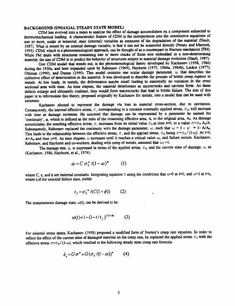
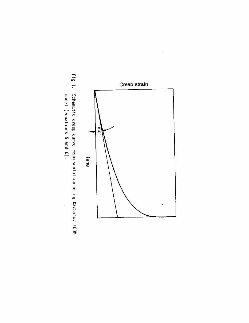
Figure 1 shows a schematic representation of a typical creep curve as described by the isothermal steadystate constitutive equations 5 and 6 (Penny & Marriott, 1995). It is apparent from the curve that the steady stateCDM model as described by Kachanov (1986) includes the features of tertiary creep following an initial minimumcreep rate that remains essentially constant for the first 25% of life. At time zero when t,_0, equation 4 indicates thatthe steady state creep rate collapses to the Norton equation. As time elapses and the damage o increases, the creeprate increases accordingly. Hence, due to the incorporation of the current damage state into the model, the steady
state creep rate does not remain constant but rather tends to infinity as t -* tt, and hence _ -, a_=l. According toPenny and Marriott (1995), and using the Kachanov model, most of the damage occurs later than 80% of life.
THEORY AND DAMAGE LAWS
Generalized Anisothermal Uniaxial Constitutive Model
The Kachanov model presented above was derived to describe the creep brittle rupture of metals, assumingisothermal steady state conditions. In addition, this model assumes that at failure a complete loss of mtegrity of the
material occurs, which corresponds to o_l. This condition results in the creep rate tending to infinity as t -, tf.In ceramics where tertiary creep behavior is observed, the creep rate increases as the failure time is
approached but does not go to infinity. In addition, the assumption that a complete state of damage given by thecondition that or=l is not observed experimentally in ceramics or even in many metals. Mennon, at al. (1994)
observed that in a mile silicon nitride NT-154 specimen tested at 1400 °C and failed at a strain of 2.5%, the ratioof cavitated area to the total area of the specimen was 5.5%. Penny and Marriott (1995) state that there are goodreasons why o at failure should be less than unity and devoted an appendix m there book to prove that point. Statureand yon Estorff (1992) who used ultrasonic techniques to determine cavity densities in steels concluded that thevalue of o at failure is no where near unity, as was assumed by Kachanov. Hazime and White (1996) formulated aphenomenological damage model containing a hardening variable used to captule the continuous drop in creep rateswith strain, observed in many ceramics. In there model they assumed that failure occurs when the damage reaches acritical value of,which is predetrmined experimentally.
In this section, a generalized amsothemml CDM model that takes into account temperature variation andmodels the entire creep curve, including the primary and tertiary creep regions, will be derived. This model will takeinto account the effect of the current state of damage on the creep strain and strain rate accumulation. In addition,this model is generalized to capture the creep behavior of materials across the specman, staring with materials that
display absolutely no tertiary creep characteristics, and ending with those showing severe tertiary behavior. Unlikethe Hazime model, this generalized formulation does not require _ to be measured or known apriori, but rather iscomputed as a material parameter via nonlinear regression using standard creep dam.
Primary creep can be taken into account by multiplying the damage rate and creep rate (equations 1 and 4)by the term fm, where t is the time and m is a material parameter. Additionally, temperature dependence can beaccounted for by multiplying equations 1 and 4 by an Arhenius type temperature formulation. Hence, the damagerate and creep rote can be described as:
do) C t m e -Q_/RT
= dt (1- o)(t)) * 0.°(7)
( In_=d S=G t= e-_../m aodt 1-o)(t)
(s)
where C, x, m, ¢, QD, (3, n, and Qo are matmal constants to be determin_ via nonlinear regression of creep data, R
is the gas constant (8.31 Mmol.K), and T is the absolute teml_ramre. The parameters QD and Qc _t the
activation en_-giea for damage and creep, r_aectivcly. The stress exponent, n, should be a positive number, while
the time exponent, m, is generally negative.
Integrating equation 7, and using the conditions that at time zero, the damage t_O, and that at the time offailure tf, the damage reaches a critical value of, results in the following formula for the time to failure:
4 I
t:=(O+m)e_'/Rr[1-O-o):_+'ql'*--_C(1 +#)o. °(9)
Equation 9 can be rewritten to obtain an expression describing of in terms of stress, temperature, and the lime tofailure:
1
fl+m
-f
co:=1- 1 C(l+#)e-Q_/m(l+m) °'°] 1-7/(10)
A function describing the cm_nt state of damage as a function of time, _(t), can be derived by integrating equation
7, or by substituting t for tf m equation 10:
I
o)(t)=l-[l C(l+_)e-Q_/"r(l+m)t'÷"°'°]]'-J(11)
Another useful expression for the current state of damage, can be derived by combining equations 9 and 11:
I
1-('1""o)(t):l-{ _,_-/)[1-O-o)f_**]l
(12)
Now that the damage evolution has been derived, we will turn our attention to the creep strainaccumulation and the effect of the cmcent state of damage on it. The creep rate expression was given earlier throughequation 8. Substituting equation 12 into equation 8 yields the following alternative expression for the creep rate:
--N
{I +i 1}_=Gtmcr oe -g/Rr 1- 1-O-r.ofy ÷' (13)
Finally, upon integration of equation 13, an expression describing how the creep strain varies with time,temperature, and stress is derived:
G t_+" cro e -Q</Rr
+'1,++j- {E -},_, (,)'-- _['-(' (14)
Equation 14 describes the entire creep curve, including the primary, secondary, and tertiary regions. Depending on
the value for t_f, equation 14 can simulate creep curves with severe tertiary behavior (_-* 1) as well as creep curves
displaying no tertiary characteristics (_ -, 0). This behavior can be visualized by setting co=_f in the creep rateequation 8, which results in formulation for the creep rate at failure. The creep strain Equation 14 can be rewritten interms of the current state of damage _(t) as follows:
_'(t)=G t) +mO"o"e -_'/Rr
(1 + m)( .1+ _ - ")i+--_ ) _- (1- °),y+']
{1- [1- o)(t)] l+_-" } (15)
An expression for the rupture strain, el, can be obtained by setting _'=_in equation 15:
Go-g I+m -QelRT
e.i _ t i e {1-[1-coy l +_" } (16)
O+m)(l++-n) [1-O-wfy+_']l+@
Note that all the equations derived in this section will collapse to Kachanov's isothermal steady state formulation ffthe activation energies and the time exponent parameters (QD, Qc, m), are set to zero, and _= 1.
A worthwhile discussion at this point is one that relates the damage accumulation using the Robinson's
(1952) time fraction nile, D, and the CDM current state of damage, to. This is necessary because under conditions ofvarying temperature and/or stress conditions, the Robinson's linear damage munn_tion rule is utilized to predictcreep rupture. In order to accomplish this task of comparing these two formulations, let us first rewrite equation 12into the following form:
t'-m_
tf
1
1-(1-coy-'1-O-cof_ ÷'(17)
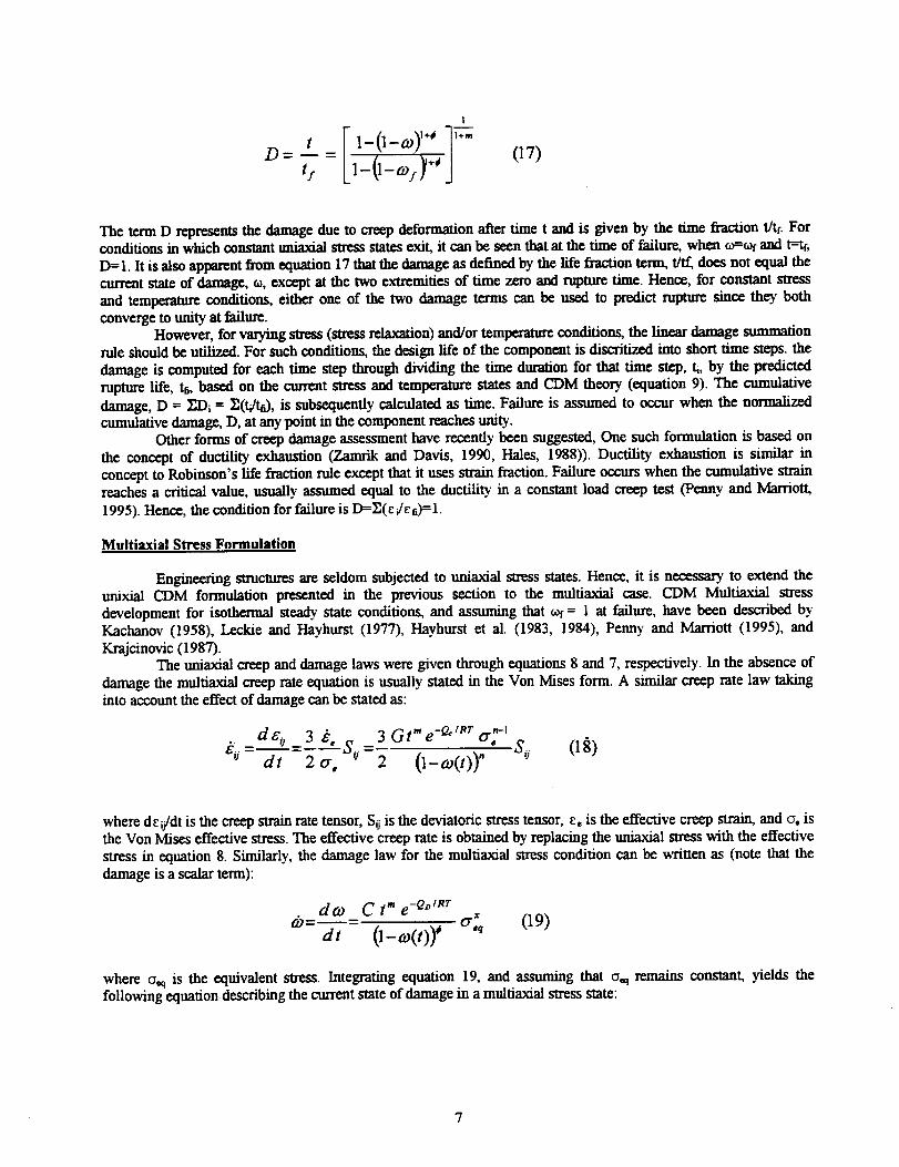
The term D represents the damage due to creep deformation after time t and is given by the time fraction t/tf. Forconditions in which constant uniaxial stress states exit, it can be seen that at the time of failure, when ¢_,=ofand t=tf,
D=I. It is also apparent from equation 17 that the damage as defined by the life fraction term, t/_ does not equal thecurrent state of damage, ¢_,except at the two extremities of time zero and rupture time. Hence, for constant stressand temperature conditions, either one of the two damage terms can be used to predict rupture since they bothconverge to unity at failure.
However, for varying stress (stress relaxation) and/or temperature conditions, the linear damage summationrule should be utilized. For such conditions, the design life of the component is discritized into short lime steps, the
damage is computed for each time step through dividing the time duration for that time step, ti, by the predictedrupture life, te, based on the current stress and temperature states and CDM theory (equation 9). The cumulative
damage, D = ]_Di = _(_tD, is subsequently calculated as time. Failure is assumed to occur when the normalizedcumulative damage, D, at any point in the component reaches unity.
Other forms of creep damage assessment have recently been suggested, One such formulation is based on
the concept of ductility exhaustion (Zamrik and Davis, 1990, Hales, 1988)). Ductility exhaustion is similar inconcept to Robinson's life fraction rule except that it uses strain fraction. Failure occurs when the cumulanve strainreaches a critical value, usually assumed equal to the ductility in a constant load creep test (Penny and Marriott,
1995). Hence, the condition for failure is D=_(c./ee)=l.
Multiaxial Stress Formulation
Engineering structures are seldom subjected to umaxial stress states. Hence, it is necessary to extend theunixial CDM formulation presented in the previous section to the multiaxial case. CDM Multiaxial stress
development for isothermal steady state conditions, and assuming that COl= 1 at failure, have been described byKachanov (1958), Leckie and Hayhurst (1977), Hayhurst et al. (1983, 1984), Penny and Marriott (1995), and
IG-ajcinovic (1987).The uuiaxial creep and damage laws were given through equations 8 and 7, respectively. In the absence of
damage the multiaxial creep rate equation is usually stated in the Von Mises form. A similar creep rate law takinginto account the effect of damage can be stated as:
. d8 o _3 P., 3 Gt'e -°''Rr cr,_-I Soe'° dt 2 cr_S'J-2 O-co(t))"
where de_j/dt is the creep strain rate tensor, Sij is the deviatoric stress tensor, c, is the effective creep strain, and o. isthe Von Mises effective stress. The effective creep rate is obtained by replacing the uniaxial stress with the effectivestress in equation 8. Similarly, the damage law for the multiaxial stress condition can be written as (note that the
damage is a scalar term):
dco C t" e -°°/m
co=dt O-co(t))# °'_q (19)
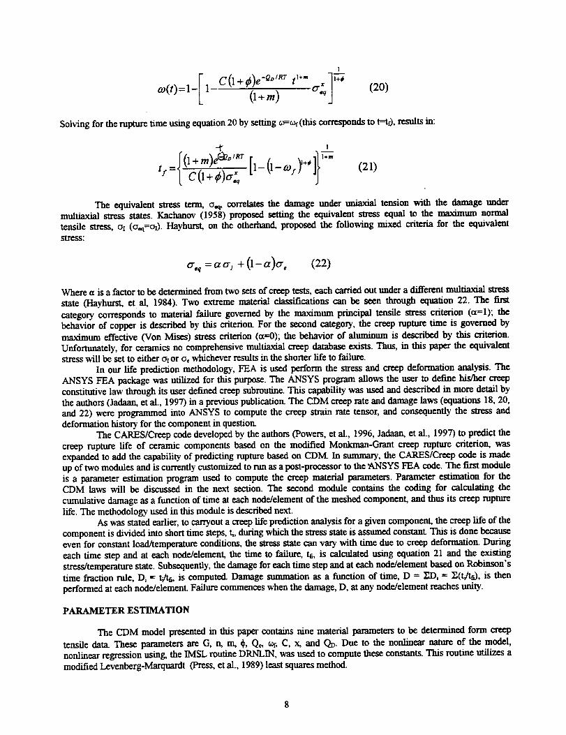
where o,q is the equivalent stress. Integrating equation 19, and assuming that o.q remains constant, yields thefollowing equation describing the current state of damage in a multiaxial stress state:
7
1
co(t)=l-[ I C(I+ _)e-Q°/Rr t_+_ * -]j-_0+m) (2o)
Solving for the rupture time using equation 20 by setting o=_(this corresponds to t--t0, results in:
(21)
The equivalent stress term, o,q, correlates the damage under unlaxial tension with the damage undermuitiaxial _ states. Kachanov (1958) proposed setting the equivalent stress equal to the maximum normaltensile stress, Ol (o.q=ot). Hayhurst, on the otherhand, proposed the following mixed criteria for the equivalentstress:
o',_ =acr I + (1-a)o-, (22)
Where a is a factor to be determined from two sets of creep tests, each carried out under a different multiaxial stress
state (Hayhurst, et al, 1984). Two extreme material classifications can be seen through equation 22. The firstcategory corresponds to material failure governed by the maximum principal tensile stress criterion (a=l); thebehavior of copper is described by this criterion. For the second category, the creep rapture time is governed bymaximum effective (Vun Mises) stress criterion (a=O); the behavior of aluminum is described by this criterion.Unfortunately, for ceramics no comprehensive multiaxial creep database exists. Thus, in this paper the equivalentstress will be set to either o_or o, whichever results in the shorter life to failure.
In our life prediction methodology, FEA is used perform the stress and creep deformation analysis. TheANSYS FEA package was utilized for this purpose. The ANSYS program allows the user to define hLCher creepconstitutive law through its user defined creep subroutine. This capability was used and described in more detail bythe authors (Jadaan, et al., 1997) in a previous publication. The CDM creep rate and damage laws (equations 18, 20,and 22) were programmed into ANSYS to compute the creep strain rate tensor, and consequently the stress anddeformation history for the component in question
The CARES/Creep code developed by the authors (Powers, et al., 1996, Jadaan, et al., 1997) to predict thecreep rupture life of ceramic components based on the modified Monkman-Grant creep rupture criterion, wasexpanded to add the capability of predicting rupture based on CDM. In summary, the CARES/Creep code is madeup of two modules and is currently customized to run as a post-processor to the "A,NSYS FEA code. The first moduleis a parameter estimation program used to compute the creep material parameters. Parameter estimation for theCDM laws will be discussed in the next section. The second module contains the coding for calculating the
cumulative damage as a function of time at each node/element of the meshed component, and thus its creep rupturelife. The methodology used in this module is described next.
As was stated earlier, to carryout a creep life prediction analysis for a given component, the creep life of the
component is divided into short time steps, ti, during which the stress state is assumed constant. This is done becauseeven for constant load/temperature conditions, the stress state can vary with time due to creep deformation. Duringeach time step and at each node/element, the time to failure, h, is calculated using equation 21 and the existingstress/temperature state. Subsequently, the damage for each time step and at each node/element based on Robinson'stime fraction rule, D_ = t/h, is computed. Damage summation as a function of time, D = IIDi = If(t/t0, is thenperformed at each node/element. Failure commences when the damage, D, at any node/element reaches unity.
PARAMETER ESTIMATION
The CDM model presented in this paper contains nine material parameters to be determined form creep
tensile data. These parameters are G, n, m, ¢, Qo, _, C, x, and QD. Due to the nonlinear nature of the model,nonlinear regression using the IMSL routine DRNLIN, was used to compute these constants. This routine utilizes amodified Levenberg-Marquardt (Press, et al., 1989) least squares method.
8
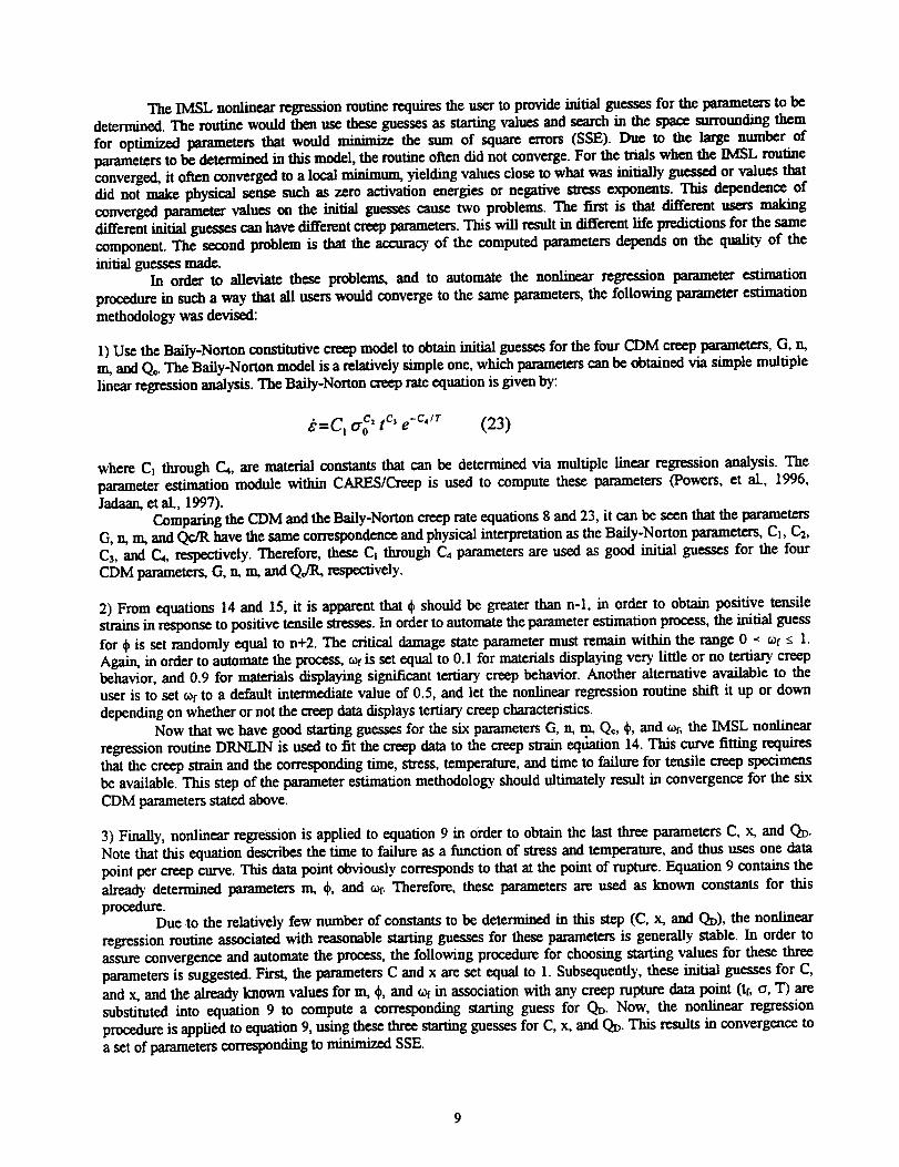
The IMSL nonlinear regression routine requires the user to provide initial guesses for the parameters to bedetermined. The routine would then use these guesses as starting values and search in the space surrounding them
for optimized parameters that would minimize the sum of square errors (SSE). Due to the large number ofparameters to be determined in this model, the routine often did not converge. For the trials when the IMSL routineconverged, it often converged to a local IDinimnm yielding values close to what was mitiaUy guessed or values thatdid not make physical sense such as zero activation energies or negative stress exponents. This dependence ofconverged parameter values on the h-filial guesses cause two problems. The first is that different users makingdifferent initial guesses can have different creep parameters. This will result in different life predictions for the samecomponent. The second problem is that the accuracy of the computed parameters depends on the quality of the
initial guesses made.In order to alleviate these problems, and to automate the nonlinear regression parameter estimation
procedure in such a way that all users would converge to the same parameters, the following parameter estimationmethodology was devised:
1) Use the Bally-Norton constitutive creep model to obtain initial guesses for the four CDM creep parameters, G, n,m, and Q_. The Baily-Norton model is a relatively simple one, which parameters can be obtained via simple multiple
linear regression analysis. The Baily-Norton creep rate equation is given by:
_'=C, o "c, t c' e -c',r (23)
where C_ through C4, are material constants that can be determined via multiple linear regression analysis. Theparameter estimation module within CARES/Creep is used to compute these parameters (Powers, et al., 1996,
Jadaan, et al., 1997).Comparing the CDM and the Baily-Norton creep rate equations 8 and 23, it can be seen that the parameters
G, n, m, and Qc/R have the same correspondence and physical interpretation as the Baily-Norton parameters, C_, Ca,C3, and C,4, respectively. Therefore, these C_ through C4 parameters are used as good initial guesses for the four
CDM parameters, (3, n, m, and Q,/R, respectively.
2) From equations 14 and 15, it is apparent that ¢bshould be greater than n-l, in order to obtain positive tensilestrains in response to positive tensile stresses. In order to automate the parameter estimation process, the initial guess
for dpis set randomly equal to n+2. The critical damage state parameter must remain within the range 0 -_ a)f g 1.Again, in order to automate the process, _ is set equal to 0.1 for materials displaying very little or no tertiary creepbehavior, and 0.9 for materials displaying significant tertiary creep behavior. Another alternative available to theuser is to set wf to a default intermediate value of 0.5, and let the nonlinear regression routine shift it up or down
depending on whether or not the creep data displays tertiary creep characteristics.Now that we have good starling guesses for the six parameters G, n, m, Qc, _b,and col, the IMSL nonlinear
regression routine DRNLIN is used to fit the creep data to the creep strain equation 14. This curve fitting requiresthat the creep strain and the corresponding time, stress, temperature, and time to failure for tensile creep specimensbe available. This step of the parameter estimation methodology should ultimately result in convergence for the six
CDM parameters stated above.
3) Finally, nonlinear regression is applied to equation 9 in Order to obtain the last three parameters C, x, and QD.Note that this equation describes the time to failure as a function of stress and temperature, and thus uses one datapoint per creep curve. This data point obviously corresponds to that at the point of rupture. Equation 9 contains thealready determined parameters m, _b, and _. Therefore, these parameters are used as known constants for this
procedure.Due to the relatively few number of constants to be determined in this step (C, x, and QD), the nonlinear
regression routine associated with reasonable starting guesses for these parameters is generally stable. In order toassure convergence and automate the process, the following procedure for choosing starting values for these threeparameters is suggested. First, the parameters C and x are set equal to 1. Subsequently, these initial guesses for C,and x, and the already known values for m, _b,and _ in association with any creep rupture data point (tr, o, T) aresubstituted into equation 9 to compute a corresponding starting guess for QD. Now, the nonlinear regression
procedure is applied to equation 9, using these three starling guesses for C, x, and QD. This results in convergence toa set of parameters corresponding to minimized SSE.
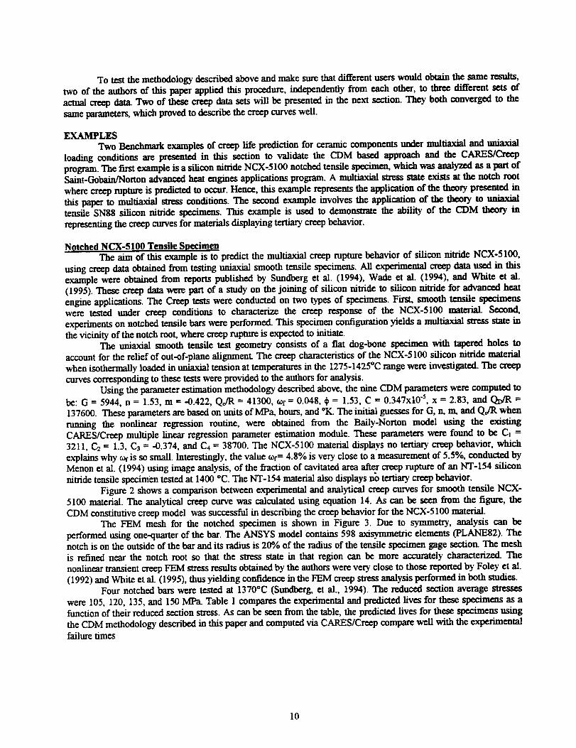
To test the methodology described above and make sure that different users would obtain the same results,two of the authors of this paper applied this procedure, independently from each other, to three different sets ofactual creep data. Two of these creep data sets will be presented in the next section. They both converged to the
same parameters, which proved to describe the creep curves well.
EXAMPLESTwo Benchmark examples of creep life prediction for ceramic components under multiaxial and uniaxial
loading conditions are presented in this section to validate the CDM based approach and the CARES/Creepprogram. The first example is a silicon nitride NCX-5100 notched tensile specimen, which was analyzed as a part ofSaint-Gobain/Norton advanced heat engines applications program. A multiaxial stress state exists at the notch root
where creep rapture is predicted to occur. Hence, this example represents the application of the theory presented inthis paper to multiaxial stress conditions. The second example involves the application of the theory to uniaxialtensile SN88 silicon nitride specimens. This example is used to demonsWate the ability of the CDM theory in
representing the creep curves for materials displaying tertiary creep behavior.
Notched NCX-5100 Tensile SpecimenThe aim of this example is to predict the multiaxial creep rupture behavior of silicon nitride NCX-5100,
using creep data obtained from testing uniaxial smooth tensile specimens. All experimental creep data used in thisexample were obtained from reports published by Sundberg et al. (1994), Wade et al. (1994), and White et al.(1995). These creep data were part of a study on the joining of silicon nitride to silicon nitride for advanced heatengine applications. The Creep tests were conducted on two types of specimens. First, smooth tensile specimenswere tested under creep conditions to characterize the creep response of the NCX-5100 material. Second,experiments on notched tensile bars were performed. This specimen configuration yields a multiaxial stress state inthe vicinity of the notch root, where creep rupture is expected to initiate.
The uniaxial smooth tensile test geometry consists of a flat dog-bone specimen with tapered holes toaccount for the relief of out-of-plane alignment. The creep characteristics of the NCX-5100 silicon mtride materialwhen isothermally loaded in unlaxial tension at temperatures in the 1275-1425°C range were investigated. The creepcurves corresponding to these tests were provided to the authors for analysis.
Using the parameter estimation methodology desodbed above, the nine CDM parameters were computed tobe: G -- 5944, n = 1.53, m = -0.422, Qo/R = 41300, Gof= 0.048, _b= 1.53, C = 0.347x10 "s, x = 2.83, and QD/R =137600. These parameters are based on units of MPa, hours, and °K. The initial guesses for G, n, m, and Qo/R whenrunning the nonlinear regression routine, were obtained from the Baily-Nonon model using the existingCARES/Creep multiple linear regression parameter estimation module. These parameters were found to be C_ =3211, C2 = 1.3, C3 = -0.374, and C4 = 38700. The NCX-5100 material displays no tertiary creep behavior, whichexplains why COlis so small. Interestingly, the value _-- 4.8% is very close to a measurement of 5.5%, conducted byMenon et al. (1994) using image analysis, of the fraction of cavitated area after creep rupture of an NT-154 siliconmtride tensile specimen tested at 1400 °C. The NT-154 material also displays no tertiary creep behavior.
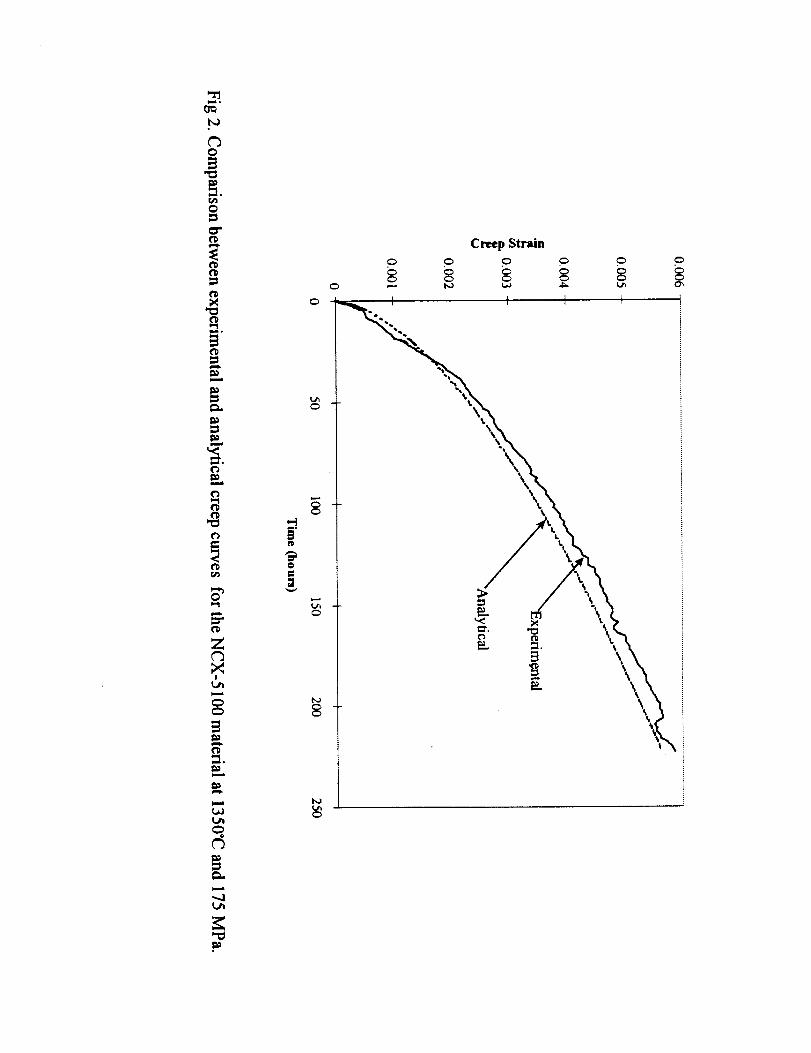
Figure 2 shows a comparison between experimental and analytical creep curves for smooth tensile NCX-5100 material. The analytical creep curve was calculated using equation 14. As can be seen from the figure, theCDM constitutive creep model was successful in describing the creep behavior for the NCX-5100 material.
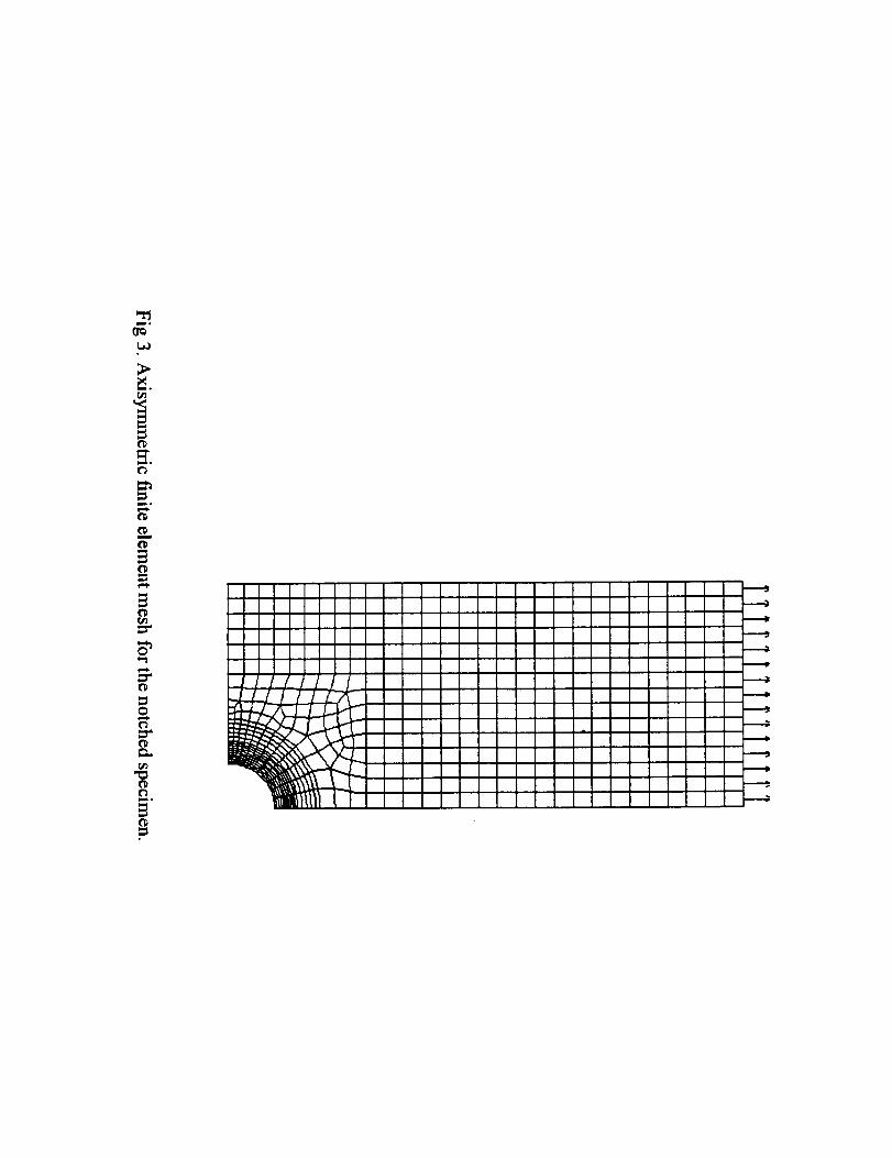
The FEM mesh for the notched specimen is shown in Figure 3. Due to symmetry, analysis can beperformed using one-quarter of the bar. The ANSYS model contains 598 axisymmetric elements (PLANE82). Thenotch is on the outside of the bar and its radius is 20e of the radius of the tensile specimen gage section. The meshis refined near the notch root so that the stress state in that region can be more accurately chamcterizccL The
nonlinear transient creep FEM stress results obtained by the authors were very close to those reported by Foley et al.(1992) and White et al. (1995), thus yielding confidence in the FEM creep stress analysis performed in both studies.
Four notched bars were tested at 1370°C (Sundberg, et al., 1994). The reduced section average slresseswere 105, 120, 135, and 150 MPa. Table 1 compares the experimental and predicted lives for these specimens as afunction of their reduced section stress. As can be seen from the table, the predicted lives for these specimens using
the CDM methodology described in this paper and computed via CARES/Creep compare well with the experimentalfailure times
l0
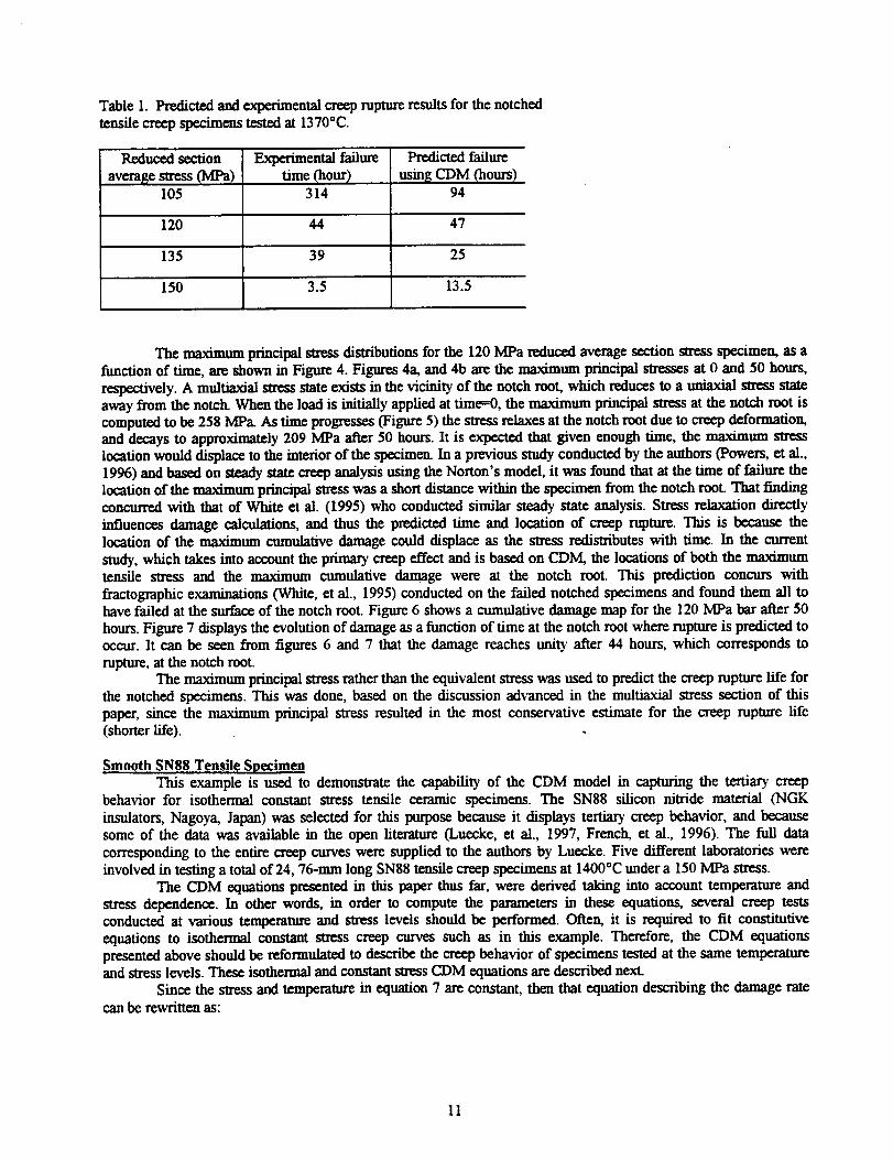
Table1. Predicted and experimental creep rupture results for the notchedtensile creep specimens tested at 1370°C.
l_duced section
averagestress(MPa)105
Experimental failuretime (hour)
314
Predicted failure
nsm S CDM (hours)94
120 44 47
135 39 25
150 3.5 13.5
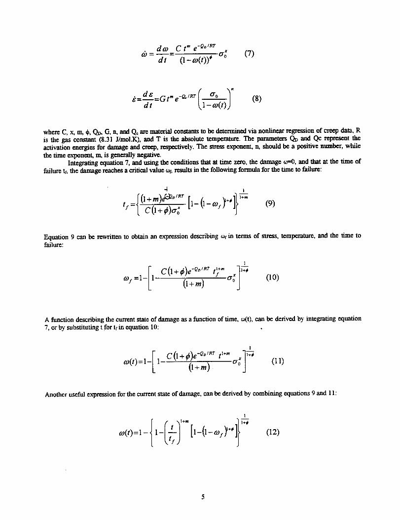
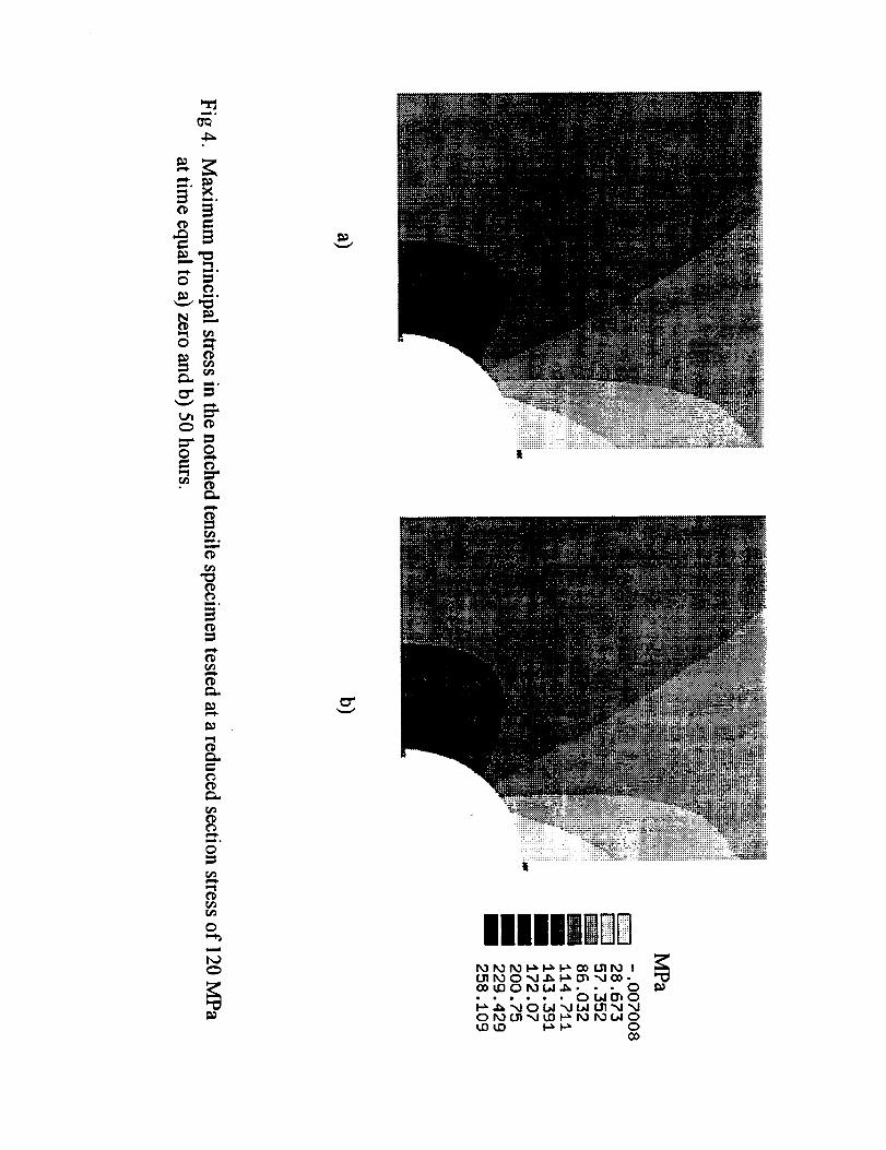
The maximum principal stress distributions for the 120 MPa reduced average section stress specimen, as afunction of time, are shown m Figure 4. Figures 4a, and 4b are the maximum principal stresses at 0 and 50 hours,
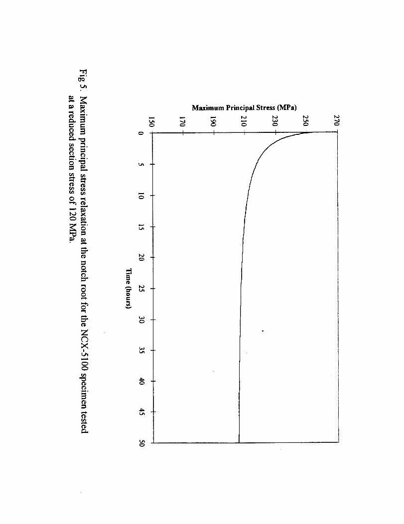
respectively. A multiaxial stress state exists in the vicinity of the notch root, which reduces to a uniaxial stress stateaway from the notch. When the load is initially applied at time=0, the maximum principal stress at the notch root iscomputed to be 258 MPa As time progresses (Figure 5) the stress relaxes at the notch root due to creep deformation,and decays to approximately 209 MPa after 50 hours. It is expected that given enough time, the maximum stresslocation would displace to the interior of the specimen. In a previous study conducted by the authors (Powers, et al.,1996) and based on steady state creep analysis using the Norton's model, it was found that at the time of failure thelocation of the maximum principal stress was a short distance within the specimen from the notch mot. That findingconcurred with that of White et al. (1995) who conducted similar steady state analysis. Stress relaxation directlyinfluences damage calculations, and thus the predicted time and location of creep rupaue. This is because thelocation of the maximum cumulative damage could displace as the stress redistributes with time. In the currentstudy, which takes into account the primary creep effect and is based on CDM, the locations of both the maximumtensile stress and the maximum cumulative damage were at the notch mot. This prediction concurs with
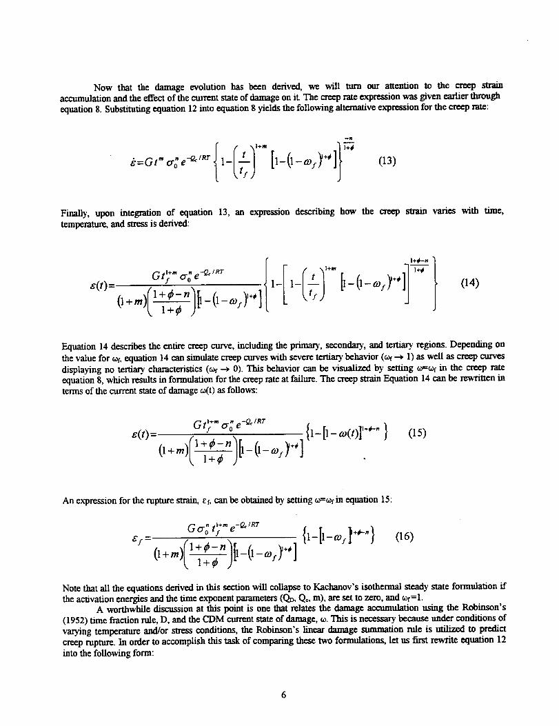
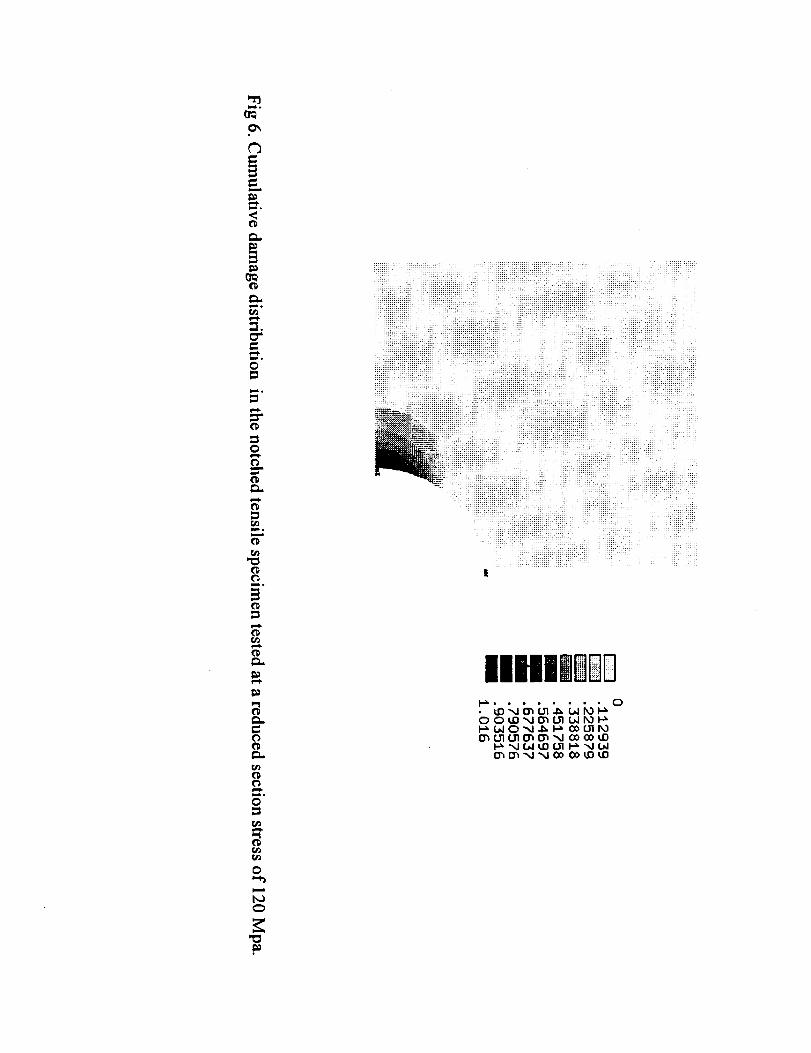
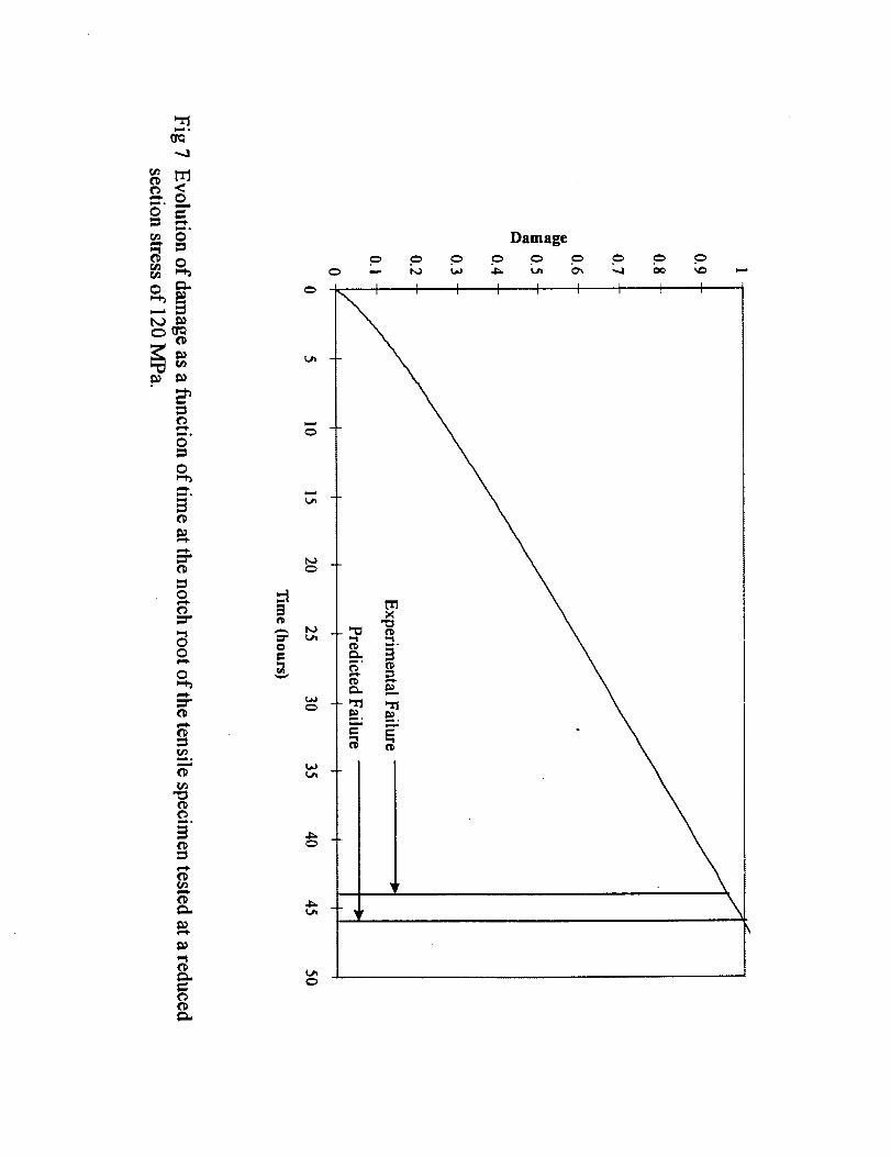
fractographic examinations (White, et al., 1995) conducted on the failed notched specimens and found them all tohave failed at the surface of the notch root. Figure 6 shows a cumulative damage map for the 120 MPa bar after 50hours. Figure 7 displays the evolution of damage as a function of time at the notch root where rupture is predicted tooccur. It can be seen from figures 6 and 7 that the damage reaches unity after 44 hours, which corresponds torupture, at the notch mot.
The maximum principal stress rather than the equivalent stress was used to predict the creep rupture life forthe notched specimens. This was done, based on the discussion advanced in the multiaxial stress section of thispaper, since the maximum principal stress resulted in the most conservative estimate for the creep rupture life(shorter life).
Smooth SN88 Tensile SpecimenThis example is used to demonstrate the capability of the CDM model in capturing the tertiary creep
behavior for isothermal constant stress tensile ceramic specimens. The SN88 silicon mtride material (NGK
insulators, Nagoya, Japan) was selected for this purpose because it displays tertiary creep behavior, and becausesome of the data was available in the open literature (Luecke, et al., 1997, French, et al., 1996). The furl data
corresponding to the entire creep curves were supplied to the authors by Luecke. Five different laboratories wereinvolved in testing a total of 24, 76-mm long SN88 tensile creep specimens at 1400"C under a 150 MPa stress.
The CDM equations presented m this paper thus far, were derived taking into account temperature andstress dependence. In other words, m order to compute the parameters in these equations, several creep testsconducted at various temperature and slress levels should be performed. Often, it is required to fit constitutiveequations to isothermal constant stress creep curves such as in this example. Therefore, the CDM equationspresented above should be reformulated to describe the creep behavior of specimens tested at the same temperatureand stress levels. These isothermal and constant stress CDM equations are described next.
Since the stress and temperature in equation 7 are constant, then that equation describing the damage ratecan be rewritten as:
11
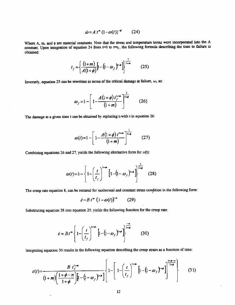
d)=.4 t" (1-co(t)) -* (24)
Where A, m, and ¢ are material constants. Note that the stress and temperature terms were incorporated into the Aconstant Upon integration of equation 24 from t=O to t=tt, the following formula describing the time to failure isobtained:
1
r0+_)__0__o,_+,]}_'<='IAO+#)(25)
Inversely, equation 25 can be rewritten in terms of the critical damage at failure, of, as:
I
o,_=I-I (I+,.) (26)
The damage at a given time t can be obtained by replacing tfwith t in equation 26:
1
o<,,:1_I, (l+m) ' (27)
Combining equations 26 and 27, yields the following alternative form for o(t):
1
{1_¢,1'+.co(t)=l - !tTf ) [1-0-co.c)l+' ]} I-7-7 (28)
The creep rate equation 8, can be restated for isothermal and constant stress condition in the following form:
_=Bt" (1 -co(t))-" (29)
Substituting equation 28 into equation 29, yields the following function for the creep rate:
--4
1_I,1,+- -_,__:""{ mJ I'-o-°')+'ll (30)
Integrating equation 30 results in the following equation describing the creep strain as a function of time:
B #1+m {"<'>:( '-O+m) 1 (1- cos._+' ]1+¢ )"
I+(i--.l
(31)
12
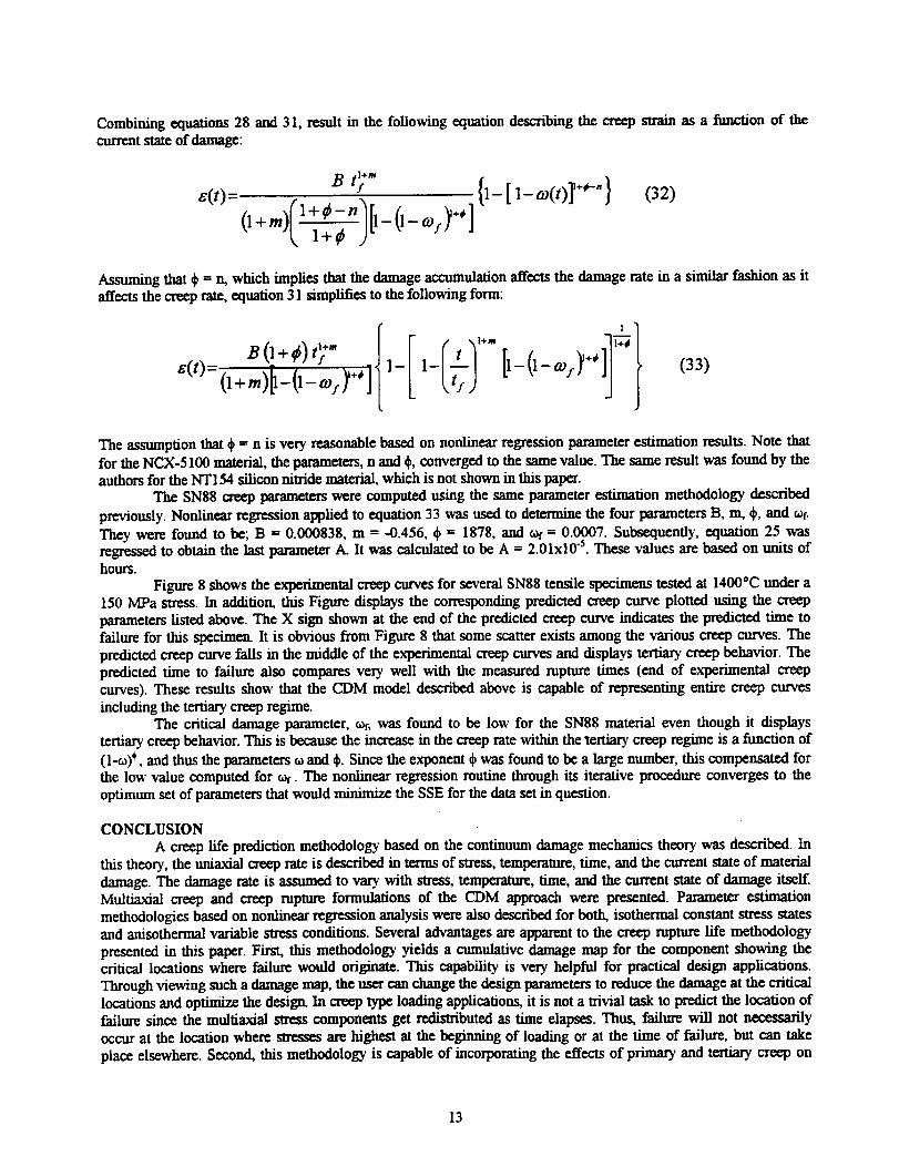
Combiningequations 28 and 31, result in the following equation describing the creep strain as a function of thecurrent state of damage:
e(t)=B tl+m-f
+¢_-n
(1 +m)(1 _-_ )[1- (1- co:y"]
{1-[ 1- co(t)] l+*'" } (32)
Assuming that & = _ which implies that the damage accumulation affects the damage rate in a similar fashion as itaffects the creep rate, equation 31 simplifies to the following form:
fEB (1+_) t_÷" 1 t
6(t)=(l+m)__(l_aT:y+, ] 1--_--3 [1-(1-co/Y +'(33)
The assumption that ¢ = n is very reasonable based on nonlinear regression parameter estimation results Note thatfor the NCX-5100 material, the parameters, n and d_,converged to the same value. The same result was found by theauthors for the NT154 silicon nitride material, which is not shown in this paper.
The SN88 creep parameters were computed using the same parameter estimation methodology described
previously. Nonlinear regression applied to equation 33 was used to determine the four parameters B, m, ¢, and t_f.They were found to be; B = 0.000838, m = -0.456, ¢ = 1878, and _ = 0.0007. Subsequently, equation 25 wasregressed to obtain the last parameter A. It was calculated to be A = 2.01x10 5. These values are based on units ofhours.
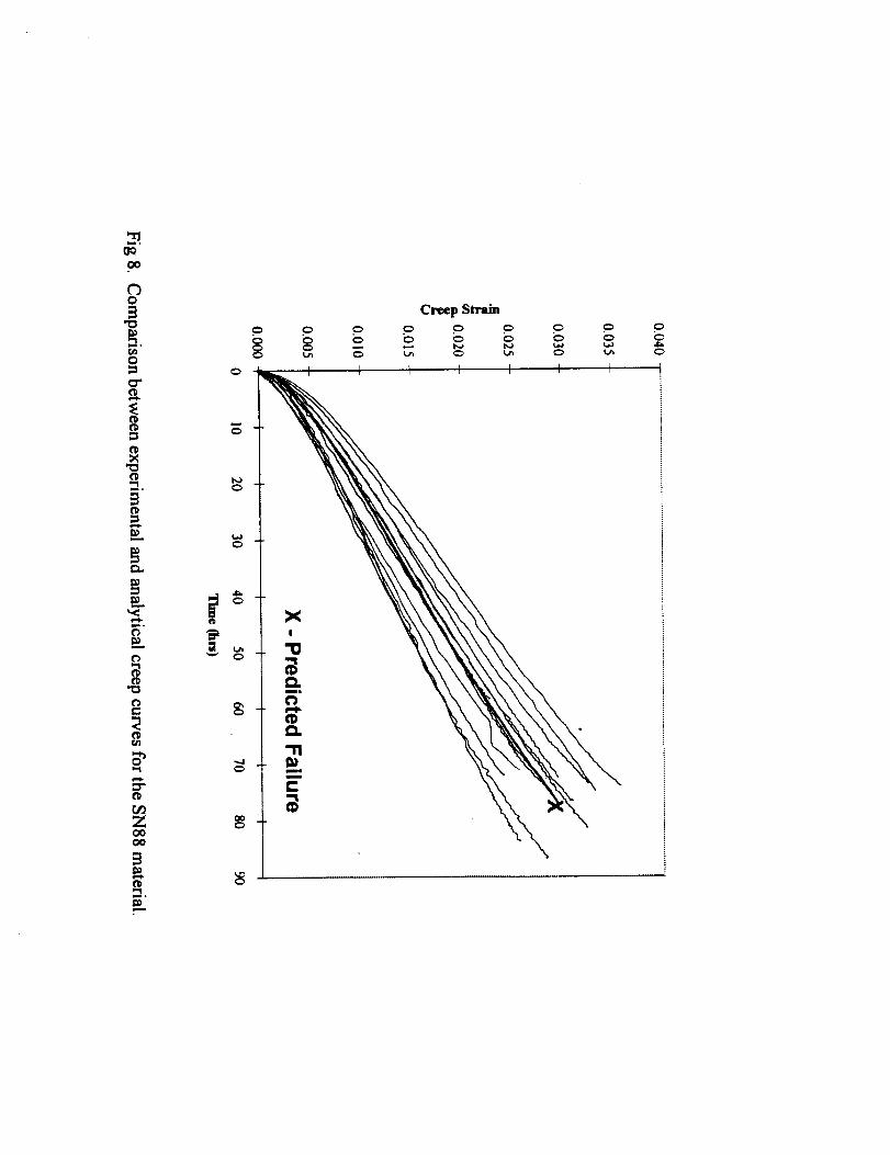
Figure 8 shows the experimental creep curves for several SN88 tensile specimens tested at 1400"C under a150 MPa stress. In addition, this Figure displays the corresponding predicted creep curve plotted using the creepparameters listed above. The X sign shown at the end of the predicted creep curve indicates the predicted time tofailure for this specimen. It is obvious from Figure 8 that some scatter exists among the various creep curves. Thepredicted creep curve falls in the middle of the experimental creep curves and displays tertiary creep behavior. Thepredicted time to failure also compares very well with the measured rupture times (end of experimental creepcurves). These results show that the CDM model described above is capable of representing entire creep curves
including the tertiary creep regime.The critical damage parameter, c_f, was found to be low for the SNSg material even though it displays
tertiary creep behavior. This is because the increase in the creep rate within the tertiary creep regime is a function of
(l-u)*, and thus the parameters _ and ¢. Since the exponent qbwas found to be a large number, this compensated forthe low value computed for c_r. The nonlinear regression routine through its iterative procedure converges to theoptimum set of parameters that would minimize the SSE for the data set in question.
CONCLUSION
A creep life prediction methodology based on the continuum damage mechanics theory was described. Inthis theory, the uniaxial creep rate is described in terms of stress, temperature, time, and the current state of materialdamage. The damage rate is assumed to vary with stress, temperanm:, time, and the current state of damage itself.Multiaxial creep and creep rupture formulations of the CDM approach were presented. Parameter estimationmethodologies based on nonlinear regression analysis were also described for both, isothermal constant stress statesand anisothermal variable stress conditions. Several advantages are apparent to the creep rupture life methodology
presented in this paper. First, this methodology yields a cumulative damage map for the component showing thecritical locations where failure would originate. This capability is very helpful for practical design applications.Through viewing such a damage map, the user can change the design parameters to reduce the damage at the criticallocations and optimize the design. In creep type loading applications, it is not a trivial task to predict the location offailure since the multiaxial stress components get redistributed as time elapses. Thus, failure will not necessarilyoccur at the location where stresses are highest at the beginning of loading or at the time of failure, but can take
place elsewhere. Second, this methodology is capable of incorporating the effects of primary and tertiary creep on
13
rupture. Third, any equivalent stress criterion can be used to predict the component's life. Fourth and perhaps most
importantly, this methodology takes into account the effect of instantaneous damage on the deformation and rupture
of the component. This creep life prediction methodology was preliminarily added to the integrated design code
CARES/Creep (Ceramics Analysis and Reliability Evaluation of Structures/Creep), which is a postprocessor
program to commercially available finite element analysis (FEA) packages. Two examples, showing comparisonsbetween experimental and predicted creep lives of ceramic specimens, were used to demonstrate the viability of this
methodology and the CARES/Creep program
REFERENCES
Duune, F. P. E., Othamn, A. NL, Hall, F. P,., and hayhurst, L. NL, 1990, "Representation of Uniaxial Creep
Curves Using Contimmm Damage Mechanics," International dournal of mechanical Science, 'Col. 32, No. 11, pp.945-957.
Ferber, M. K., and Jenkins, M. G., 1992, "Empirical Evaluation of Tensile Creep and Creep Rupture in a
HIPed Silicon Nitride," in Creep: Characterization, Damage and Life Assessment, ASM International Woodford, D.
A., Townley, C. H. A., and Ohnami, M., Eds., pp. 81-90.
Foley, NL, Rossi, G., Sundberg, G., Wade, J., and Wu, F., 1992, "Analytical and Experimental Evaluationof Joining Silicon Carbide to Silicon Carbide and Silicon Nitride to Silicon Nitride for Heat Engine Applications,"
Final Report, Ceramic Technology for Advanced Heat Engines, Oak Ridge National Lab.French, J. D., and Wiederhom, S. M., 1996, "Tensile Specimens from Ceramic Components," Journal of
the American Ceramic Society, Vol. 79, No. 2, pp. 550-552.
Hales, R., 1988, "Physical Mechanisms of Fracture in Combined Creep and Fractme, "' Proceedings .lnst
Metals Conference on materials and Engineering Design, London.
HaulL Jan, 1987, "Introduction and General Overview," Continuum Damage Mechanics Theory and
Applications, Krajcinovic, D., and Lemaitre, J., Eds., Springer-Verlag, New York.Hayhur_ D. R., Dimmer, P. R., and Cheruka, M. W., 1975, "Estimates of the Creep Rupture Lifetime of
Structures Using the finite Element method," dournal of Mechanical Physics of Solids, Vol. 23, pp. 335-355.
Hayhurst, L. M., Dimmer, P. P,., and Morrison, C. J., 1984a, "Development of Continuum Damage in theCreep Rupture of Notched Bars, "Phil Trans. R. Soc. Lond., Vol. 311, pp. 103-129.
Hayhurst, L. M., Brown, P. R., and Morrison, C. J., 1984b, "The Role of Continuum Damage in Creep
Crack Growth," Phil Trans. R. Soc. Land., Vol. 311, pp. 131-158.
Hazime, P,. M., and White, C. S., 1996,"An Internal Variable, Creep Damage Model of a Silicon Nitride,"submitted for publication in Materials Science and Engineering.
Jadaan, O. M., Powers, L. M., and Gyekenyesi, J. P., 1997, "Creep Life Prediction of Ceramic Components
Subjected to Transient Tensile and Compressive Stress States," ASME paper 97-GT-319.
Kachanov, L. M., 1958, "On Creep Rupture Time," Izv. Acad. Nauk SSSP,, Otd. Tech. Nauk, No. 8.
Kachanov, L. M., 1986, ]ntroduction to Continuum Damage mechanics, MartinusNijhof, Boston.Leckie, F. A2, Hayhurst, L. M., 1977, "Constitutive Equations for Creep Rupture," Acta Metallurgica, Vol.
25, pp. 1059-1070.
Luecke, W. E., and Wiederhom, S. M, 1997, "interlaboratory Verification of Silicon Nitride Tensile Creep
properties," Journal of the American Ceramic Society, Vol. 80, No. 4, pp. 831-838.
Menon, M., Fang, H., Wtt, D., Jenkins, M., and Ferber, M., 1994, "Creep and Stress Rupture Behavior of
an Advanced Silicon Nitride: Part HI, Stress Rupture and Monkman-Grant Relationships," Journal of the AmericanCeramic Society, Vol. 77, pp. 1235-1241.
Monkman, F., and Grant N., 1956, "An Empirical Relationship Between Rupture Life and Minimum Creep
rate in Creep-Rupture Test," Proceedings of the American Society for Testing and materials, Vol. 56, pp. 593-620.
Othraan, A. M., and hayhurst, L. M., 1990, "Multi-Axial Creep Rupture of a Model Structure Using a two
parameter material Model," International Journal of mechanical Science, Vol. 32, No. 1, pp. 35-48.
Penny, 1L K., and Marriott, D. L., 1995, Design for Creep, Chapman & hall, LondonPowers, L, M., Jadaan, O. M., and Gyekenyesi, J. P., 1996, "Creep Life of Ceramic Components Using a
Finite Element Based Integrated Design Program (CARES/Creep)," ASME paper 96-GT-369.
Press, W. H., Flannery, B. P., Teukolsky, S. *, and Vetterling, 1989, Numerical Recipes, Cambridge
University Press, Cambridge.Rabotonov, Yu. N., 1969, Creep Problems in Structural members, North-Holland, Amsterdam.
14
Robinson,E.L., 1952,"Effect of temperature Variation on the Long-Time Rupture Strength of Steels,"
Trans. ASME 74, pp. 777-780.Stature, I-L, and yon Estroff, U., 1992,'Determination of Creep Damage in Steels ," Proceedings 5_
International Conference on Creep of Materials, Florida, USA.
Sundberg, G., Vartabedian, A., Wade, J., and White, C., 1994, "Analytical and Experimental Evaluation of
Joining Silicon Carbide to Silicon Carbide and Silicon Nitride to Silicon Nitride for Advanced Heat Engine
Applications Phase 11," Final Report, Ceramic Technology Project, Oak Ridge National Lab.Todd, J. A., and Xu, A.-Y., 1989, "The High Temperature Creep Deformation of Si3N4-6Y203-2AI203, "
Journal of materials Science, Vol. 24, pp. 4443-4452.Miner, M A., 1945, "Cumulative Damage in fatigue," Journal of Applied Mechanics, Vol. 12, pp. A159-
A164.
Wade, J., White, C., and Wu, F., 1994, "Predicting Creep Behavior of Silicon Nitride Components Using
Finite Element Techniques," in Life Prediction Methodologies and Data for Ceramic Materials, ASTM STP 1201,
Brinkman, C., and Duffy, S., Eds., American Society for Testing and materials, Philadelphia, pp. 360-372.White, C., Vartabedian, A., Wade, J., and Tracey, D., 1995, "Notched Tensile Creep Testing of Ceramics,"
Materials Science and Engineering, A203, 217-221.Wiederhorn, S., Quinn, G., and Kranse, R., 1994, "F_"une Mechanism Maps: Their AppLicability to
Silicon Nitride," Life Prediction Methodologies and Data for Ceramic materials, ASTM STP-1201, Brinkman, C.
R., and Duffy, S. F., eds., American Society for Testing and materials, Philadelphia, pp. 36-61.Zamrik, S. Y., and Davis, D. C., 1990, "A Ductility Exhaustion Approach for Axial fatigue-Creep Damage
Assessment Using Type 316 Stainless Steel," ASME PVP, 215.
15
,-io
t'D._ =_
f_ -_°
C"
-_° {'D
O7 _b
I'D
,..J,0
e"
0
Creep strain
_=,,oO_
r_
m
Z
I
0
J
§-
0
%
\
\
mi°
i_.°
m
0
C_mi°
m
,-_ _.
_o
CD
Cb
CD
_.,Jo
C_
CD
C_
CD
"t
c_
C_c_
0
0
|
IIIii|HDD
m=L°
f_
c_ 5 °
I.*° _°
t_ t_
=r"
0
,-'I0o
,"I¢-k
=r-
Z
X!
L_
o
t__o
t_
t_
t_
o
L_
L_
L_
bo
to
Lo
Maximum Principal Stress (MPa)
-- to to to
m.6o
=_.t_p..,o
_..L.
in*o
O
0...i o
O
('D
o
I.m.
"Scp
t_
i!iiiiiiiiiiii!!_!i_!!_!iiiii_!_i!ii!ii!i_iii_ii_ii!!i!i_!i_iiii!_!!!_!!_iiii!ii!i_ii_i_!_!!!!iii!i!!!!_!_!iii!!!ii_iii_i!_i!i!_i_ii_!iii!i_!_i_
_!_ii_!_!!i_iiiii_!_i_i_i!i_!!_!_ii_!i_!_!iiiiiii_!i_i!ii_i_i_i_ii_ii_i_!_!i_!ii_i_i_!i_!ii_i_iii_iiiii_!i_i!_iii!!!!_!_ii!!Tiiiii_iii
k_ii_ii_i_i!ii!_iii!_i_i_!ii!i_i_iiiiiii_i!!!ii_iiii_!iiiiiiii_i!i_!!_i_i_i_iii_ii
IIHi|
t_
0 =pm°
0
0
_°
I'D
0
OO
O
N
I'D
Damage
_°
GO
0
o
X
0
o
o
c_Zo0oo
ira,.
o
m
XI
Creep Strain
L_