Embed Size (px)
Citation preview

EC3/EC4/SC4/HT3/HTX3/SC5/SC6 Series
Submersible SolidsHandling PumpsINSTALLATION, OPERATION, & PARTS MANUAL
SAFETY INFORMATIONCarefully read and follow all safety instructions in thismanual or on pump.
This is the safety alert symbol. When you see thissymbol on your pump or in this manual, look for one of thefollowing signal words and be alert to the potential for personal injury!
warns about hazards that will cause seriouspersonal injury, death or major property damage if ignored.
warns about hazards that can cause seriouspersonal injury, death or major property damage if ignored.
warns about hazards that will or can causeminor personal injury or property damage if ignored.The word NOTICE indicates special instructions which areimportant but not related to hazards.1. Read these rules and instructions carefully. Failure to
follow them could cause serious bodily injury and/or property damage.
2. Check your local codes before installing. You must com-ply with their rules.
3. Vent sewage or septic tank according to local codes.4. Do not install pump in any location classified as haz-
ardous by National Electrical Code, ANSI/NFPA 80-1984or the Canadian Electrical Code.
Hazardous voltage. Can shock,burn, or kill. During operation the pump is in water.To avoid fatal shocks, proceed as follows if pump needsservicing:
5A. Disconnect power to outlet box before unplugging pump.5B. Take extreme care when changing fuses. Do not stand
in water or put your finger in the fuse socket.5C. Do not modify the cord and plug. When using the cord
and plug, plug into a grounded outlet only. When wiringto a system control, connect the pump ground lead tothe system ground.
6. Do not run the pump dry. Dry running can overheat thepump, (causing burns to anyone handling it) and willvoid the warranty.
7. The pump normally runs hot. To avoid burns when ser-vicing pump, allow it to cool for 20 minutes after shut-down before handling it.
© 2007 S504 (Rev. 10/24/07)
293 Wright Street • Delavan, WI 53115
Motor Individual Cord Switch Setting DischargeModel Motor Full Branch Circuit Length in inches (mm) Adapter
Number HP Voltage Load Amps Required (Amps) in ft. (m) On Off SizeEC333120T 1/3 115/1 13.0 15 20 (6.1) 13.5 (343) 4.5 (114) 1-1/2"EC333120M 1/3 115/1 13.0 15 20 (6.1) – – 1-1/2"EC333220T 1/3 230/1 7.0 10 20 (6.1) 13.5 (343) 4.5 (114) 1-1/2"EC333220M 1/3 230/1 7.0 10 20 (6.1) – – 1-1/2"EC440120T 4/10 115/1 9.7 15 15 (4.6) 16.5 (419) 7.5 (191) 2"EC440120M 4/10 115/1 9.7 15 15 (4.6) – – 2"EC440220T 4/10 230/1 4.9 10 20 (6.1) 16.5 (419) 7.5 (191) 2"EC440220M 4/10 230/1 4.9 10 20 (6.1) – – 2"SC440110T 4/10 115/1 12.5 15 10 (3.0) 16 (406) 7 (178) 2"SC440110M 4/10 115/1 12.5 15 10 (3.0) – – 2"SC440120T 4/10 115/1 12.5 15 20 (6.1) 16 (406) 7 (178) 2"SC550110T 1/2 115/1 13.0 15 10 (3.0) 16 (406) 7 (178) 2"SC550110M 1/2 115/1 13.0 15 10 (3.0) – – 2"SC550120T 1/2 115/1 13.0 15 20 (6.1) 16 (406) 7 (178) 2"SC550120M 1/2 115/1 13.0 15 20 (6.1) – – 2”SC550220T 1/2 230/1 8.0 15 20 (6.1) 16 (406) 7 (178) 2"SC550220M 1/2 230/1 8.0 15 20 (6.1) – – 2"SC650110T 1/2 115/1 9.0 10 10 (3.0) 18 (457) 8.5 (216) 2"SC650120T 1/2 115/1 9.0 10 20 (6.1) 18 (457) 8.5 (216) 2"SC650120M 1/2 115/1 9.0 10 20 (6.1) – – 2"SC650220M 1/2 230/1 5.0 10 20 (6.1) – – 2"HT333120T 1/3 115/1 13.0 15 20 (6.1) 13.5 (343) 4.5 (114) 1-1/2"HTX333120M 1/3 115/1 13.0 15 20 (6.1) 1-1/2"
MOTOR, SWITCH, & CORD SPECIFICATIONS

8. The pump is permanently lubricated. No oiling or greas-ing is required in normal operation. for overhaul, seeinstructions under “Service”.
DESCRIPTIONThese submersible sump/effluent and sewage pumps aredesigned for effluent and wastewater removal, sump drainage,dewatering, flood control. The high temperature models can beused in boiler blow down pits, condensate pits and as hot waterpumps. Units have built in thermal overload protection with auto-matic reset. The mechanical seal and ball bearings on the motorshaft are permanently lubricated. Stainless steel hardware and aheavy duty lift out ring allow for easy disassembly after extendeduse.NOTICE: This unit is not designed for applications involving saltwater or brine! Use with salt water or brine will void warranty.
SPECIFICATIONSPower supply required...............See “Motor, Switch and Cord
Specifications” chart on Page 1Motor duty ..........................................................Continuous**Maximum Liquid Temperature............................130°F(55°C)*Discharge Adapter ......................................1-1/2” OR 2” NPT*HT3 and HT3X Series pumps have a maximum liquid tem-perature of 194°F (90°C).** For continuous duty, pump must be fully submerged in aliquid with a maximum temperature of 105° F (41° C).SC650 Series models only.
INSTALLATION Hazardous voltage. Can shock, burn or kill.
Do not lift pump by the power cord. See “Cord Lift Warning”on Page 3.NOTICE: Install the pump on a hard, level surface (cement,asphalt, etc.). Never place the pump directly on earth, clay orgravel surfaces.
PipingPiping must not be smaller than pump discharge.When installed in a sewage system, the pipe must be capable of handling semi-solids of at least 2" (51mm) indiameter.When installed in an effluent system, the pipe must be capable of handling semi-solids of at least 3/4" (19mm) indiameter.The rate of flow in the discharge pipe must keep any solidspresent in suspension in the fluid. To meet minimum flowrequirements (2 feet per second in the discharge line), sizethe pipe as follows:
A Pipe Size Of: Will Handle a Flow Rate Of:
1-1/2" (38mm) 12 GPM2" (51mm) 21 GPM2-1/2"(64mm) 30 GPM3"(76mm) 48 GPM
In a sewage system use a 2" (51mm) check valve in pump dis-charge to prevent backflow of liquid into sump basin. The checkvalve should be a free flow valve that will easily pass solids. Besure check valve installation complies with local codes.In an effluent system use a 1-1/2" (38mm) check valve inpump discharge to prevent backflow of liquid into sumpbasin. The check valve should be a free flow valve that willeasily pass solids. Be sure check valve installation complieswith local codes.NOTICE: For best performance of check valve when handlingsolids, do not install it with the discharge more than 45°above the horizontal. Do not install the check valve in a verti-cal position as solids may settle in the valve and prevent itfrom opening on startup.Drill a 3/16" (5mm) hole in the discharge pipe about 1–2" (25-51mm) above the pump discharge connection (but belowcheck valve) to prevent airlocking the pump.
Electrical
Hazardous voltage. Can shock, burn, or kill.When installing, operating, or servicing this pump, follow thesafety instructions listed below.1. DO NOT splice the electrical power cord.2. DO NOT allow the electrical cord plug to be submerged.3. DO NOT use extension cords. They are a fire hazard and
can reduce voltage sufficiently to prevent pumping and/ordamage motor.
4. DO NOT handle or service the pump while it is connect-ed to the power supply.
5. DO NOT remove the grounding prong from the plug ormodify the plug. To protect against electrical shock, thepower cord is a three-wire conductor and includes a 3-prong grounded plug. Plug the pump into a 3-wire,grounded, grounding-type receptacle. Connect the pumpaccording to the NEC or CEC and local codes.
For automatic operation, plug or wire the pump into an auto-matic float switch or duplex controller. The pump will run con-tinuously when plugged directly into an electrical outlet.Connect or wire pump to its own individual branch circuit withno other outlets or equipment in the circuit. Size fuses or cir-cuit breakers according to the “Motor, Switch and CordSpecifications” chart.
Risk of electrical shock and fire. Can burn,kill or cause property damage. Be sure that power supplyinformation (Voltage/ Hertz/Phase) on pump motor name-plate matches incoming power supply exactly. Install pumpaccording to all electrical codes that apply.
2
GPM AT TOTAL FEETModel 5 10 15 20 25 30
CAPACITY GALLONS/MINUTEEC333120T – 46 32 12 – – 22EC333120M – 46 32 12 – – 22EC333220T – 46 32 12 – – 22EC333220M – 46 32 12 – – 22EC440120T 61 52 45 38 30 21 40EC440120M 61 52 45 38 30 21 40EC440220T 61 52 45 38 30 21 40EC440220M 61 52 45 38 30 21 40SC440110T 90 66 25 – – – 18SC440110M 90 66 25 – – – 18SC440120T 90 66 25 – – – 18SC550120T 91 64 31 – – – 18SC550120M 91 64 31 – – – 18SC550110T 91 64 31 – – – 18SC550110M 91 64 31 – – – 18SC550220T 91 64 31 – – – 18SC550220M 91 64 31 – – – 18SC650110T 160 130 75 22 – – 23SC650120T 160 130 75 22 – – 23SC650120M 160 130 75 22 – – 23SC650220M 160 130 75 22 – – 23HT333120T* – 42 30 10 – – 21HTX333120M* – 42 30 10 – – 21
No flow at height
shown below
*For performance at maximum temperature see Catalog.
PERFORMANCE

OPERATIONRisk of fire or explosion. Can cause severe
personal injury, property damage or death. Do not use inexplosive atmospheres. Pump water only with this pump.NOTICE: Do not allow the pump to run in a dry sump. It willvoid the warranty and may damage the pump.An automatic overload protector in the motor will protect themotor from burning out due to overheating/overloading. Whenthe motor cools down, the overload protector will automati-cally reset and start the motor.If the overload trips frequently, check for the cause. It couldbe a stuck impeller, wrong/low voltage, or an electrical failurein the motor. If an electrical failure in the motor is suspected,have it serviced by a competent repairman.The pump is permanently lubricated. No oiling or greasing isrequired.
SERVICEGeneral
Hazardous voltage and risk of cord dam-age. Can shock, burn, or kill. Before removing the pumpfrom the basin for service, always disconnect electrical powerto the pump and the control switch. Do not lift the pump bythe power cord. See the “Cord Lift Warning” below.After removing the basin cover and the necessary dischargepiping, lift the pump out of the basin.Place the pump in an area where it can be cleaned thor-oughly. Remove all scale and deposits on the pump.Submerge the complete pump in a disinfectant solution(chlorox or chlorine bleach) for at least one hour before dis-assembling the pump.The pump motor housing contains a special lubricating oilwhich should be kept clean and free of water at all times.NOTICE: Whenever the motor housing is being removed forservice, remove oil and replace it with new oil at reassembly.Use only oil listed in parts list in this manual. When fillingwith new oil, DO NOT overfill. Allow about 7/8" (22mm) airspace from top of boss in housing for expansion of oil whenthe pump is operating.
Pump DisassemblyImpeller and Seal Replacement A. Impeller removal (See the correct pump disassembly
drawing, “Model Number Cross Reference Chart”, Page 4):1. Remove the oil fill plug and turn the pump upside
down to drain oil.2. Remove the capscrews holding the upper motor hous-
ing to the lower motor housing; lift off the upper motorhousing and remove the motor lead wires from theconnector to detach upper housing from assembly.The lead wires are fitted with quick connect terminalsfor this purpose.
3. Remove the capscrews holding the lower motor hous-ing to the volute; lift off the lower motor housing.
4. Hold the rotor shaft assembly and unscrew theimpeller by turning it counter-clockwise. Removeimpeller and clean it.If no more service is needed, reverse instructions aboveto reassemble the pump. Reattach the motor lead wiresas shown in Figure 1, fill with clean dielectric oil (PartNo. U197-8A), check the oil level and replace fill plug.Oil should cover the motor windings (E3/EC3/SC5Series) or the top of the motor (EC4 Series).
B. Shaft seal replacement:1. Follow the instructions to remove the impeller, above.2. Remove the stator capscrews and the spacers (if
applicable). Lift off the stator.3. Remove the seal’s ceramic seat from the shaft and tap
the body of the seal out of the lower motor housing.4. Clean the seal cavity thoroughly before installing the
new seal. NOTICE: Make sure that the seal faces areclean; do not scratch or damage the new seal faceduring seal replacement. Apply Permatex #2 or anequivalent sparingly to the outside edge of seal bodybefore installing the seal in the lower motor housing.
5. Press the new seal body into position in the lowerhousing cavity.
6. Press the ceramic seat onto the motor shaft. Theimpeller will pull it into position.
7. Reassemble the stator and tighten the stator cap-screws. If your pump has a capacitor (Key. No. 14), besure the spacer is under it to keep it away from the oilin the motor.
Risk of electrical shock. Can burn orkill. Discharge capacitor before handling it. Electricalshock can burn or kill.
8. Reassemble the impeller and the pump (reverseinstructions 1 through 4 in section A).
9. Install new capacitor.10. Reattach the motor lead wires as shown in Figure 1.11. Fill with clean dielectric oil (Part No. U197-8A), check
the oil level and replace the oil fill plug.
Short Divider
Either Black Wire
Either Black Wire
Green Wire
View A-A
(connected betweenthe two tallestdividers)
409 0893
Figure 1
3
1. Attempting to lift or support pump by power cordcan damage cord and cord connections.
2. Cord may pull apart, exposing bare wires withpossibility of fire or electrical shock.
3. Lifting or supporting pump by power cord willvoid warranty.
4. Use lifting ring or handle on top of pump for alllifting/lowering of pump. Disconnect power topump before doing any work on pump orattempting to remove pump from sump.
Risk of electrical shock.
Can burn or kill.
Do not lift pump by power cord.
WARNINGCORD LIFT WARNING

4
410 0893
Oil FillPlug
HousingCapscrew
Rotor/StatorAssembly
StatorCapscrew
Lower MotorHousing
Volute
Shaft Seal,Stationary Head Ass’y
Shaft Seal,Rotating Mating Ring
O-Ring
Insulating Disk
Blk
Blk
Grn
Impeller
Power Cord
Pump DisassemblyEC3/SC5/HT3/HTX3 Series
Oil fill plug
Upper motorhousing
Housing
capscrew
Power cord
connector
Blk
Blk
Grn
Rotor/Stator
Assembly
Lower Motor
Housing
Rotor/Stator
Capscrew
VoluteA
A
(See Fig. 1)
Shaft Seal, Stationary Head AssemblyShaft Seal, Rotating Mating Ring
Impeller
Spacer
Pump Disassembly – EC4 Series
NEW MODEL NO. ORIGINAL MODEL NO.EC333120T PWE3B01AEC333120M PWE3B01EC333220T PWE3B02A-04EC333220M PWE3B02-04EC440120T PWE4C01AEC440120M PWE4C01EC440220T PWE4C02AEC440220M PWE4C02SC440110T NEWSC440110M NEWSC440120T NEWSC550120T PWS5C01A-07SC550120M PWS5C01-07SC550110T PWS51C01A-07SC550110M PWS51C01-07SC550220T PWS5C02A-06SC550220M PWS5C02-06SC650110T PWS61C01ASC650120T PWS6C01ASC650120M PWS6C01SC650220M PWS6C02HT333120T PHTS3B01-06HTX333120M PHTSX3B01-06
MODEL NUMBER CROSSREFERENCE CHART

5
3917 0301 Disassmbly
Shaft Seal, Stationary Head AssemblyShaft Seal, Rotating Mating Ring
Lower Motor Housing
Impeller
Insulating Disk
Volute
Upper Motor Housing
Oil FillPlug
Capscrews
Switch Cord Clamp
Pump Disassembly – SC4 Series
Oil fill plug
Upper motorhousing
Housingcapscrew
Power cordconnector
Lower MotorHousing
Rotor/StatorAssembly
Rotor/StatorCapscrew
Volute
Shaft Seal, Stationary Head AssemblyShaft Seal, Rotating Mating Ring
Impeller
A
A
(See Fig. 1)
Pump Disassembly – SC6 Series

6
1
2
4
5
6
7
13
14
6
15A
15B
16
17
3
8
9
10
11
12
EC3/SC5/HT3/HTX3 SERIES EXPLODED VIEW
EC333120M EC333220M SC550110M SC550120M SC550220M
Key Part EC333120T EC333220T HT333120T HTX333120M SC550110T SC550120T SC550220T
No. Description Qty. 1/3 HP 115 V 1/3 HP 230 V 1/3 HP 115 V 1/3 HP 115 V 1/2 HP 115V 1/2 HP 115V 1/2 HP 230V
1 Power Cord 1 PW117-122-TSE PW117-218-TSE PW117-226-TSE § PW117-237-TSE PW117-122-TSE PW117-218-TSE2 Cord Connector 1 PS17-46P PS17-46P PS17-46P § PS17-46P PS17-46P PS17-46P3 Handle Ring 1 U97-128 U97-128 U97-128 U97-128 U97-128 U97-128 U97-1284 1/4" NPT Plug 1 U78-57DT U78-57DT U78-57DT U78-57DT U78-57DT U78-57DT U78-57DT5 Upper Motor Housing 1 PW18-22F PW18-22F PW18-22F PW18-22 PW18-22F PW18-22F PW18-22F6 #10-32 x 3/4" Capscrew 6 U30-482SS U30-482SS U30-482SS U30-482SS U30-482SS U30-482SS U30-482SS7 Insulating Disk 1 PS18-82 PS18-82 PS18-82 PS18-82 PS18-82 PS18-82 PS18-828 #10-32 x 3-1/8" Capscrew 2 U30-949ZP U30-949ZP U30-949ZP U30-949ZP U30-949ZP U30-949ZP U30-949ZP9 Rotor/Stator Assembly 1 PS218-151 — PS218-151 PS218-151 PS218-151 PS218-151 —• Rotor/Shaft Assembly 1 — PS118-151R — — — — PS118-151R• Stator 1 — PS118-153S — — — — PS118-153S
10 Switch Cord Clamp* 1 CC0030-13 CC0030-13 CC0030-13 — CC0030-13 CC0030-13 CC0030-1311 #8-32 x 1/2” Capscrew* 1 U30-539SS U30-539SS U30-539SS — U30-539SS U30-539SS U30-539SS12 Automatic Float Switch* 1 PS17-111 PW217-222 PW217-25 — PS17-109 PS17-111 PW217-22213 O-Ring 1 U9-339 U9-339 U9-339 U9-339 U9-339 U9-339 U9-33914 Lower Motor Housing 1 PW18-23AA PW18-23AA PW18-23AA PW18-23AA PW18-23AA PW18-23AA PW18-23AA15A Shaft Seal Stationary
Head Assembly 1 U9-379A U9-379A U9-379A U9-379A U9-379A U9-379A U9-379A15B Shaft Seal Rotating
Mating Ring 1 U9-321A U9-321A U9-321A U9-321A U9-321A U9-321A U9-321A16 Impeller 1 PW5-5P PW5-5P PW5-5 PW5-5 PW5-11P PW5-11P PW5-11P17 Volute 1 PW1-4 PW1-4 PW1-4 PW1-4 PW1-13 PW1-13 PW1-13• Dielectric Oil 1 U197-8A U197-8A U197-8A U197-8A U197-8A U197-8A U197-8A
• Not Illustrated.* Models w/“T” suffix only.§ Requires Replacement Cord, Part No. PW117-106-TSE.
REPAIR PARTS LIST

7
7
14
8
9
10
11
16A
12
13
4
3
2
1
6
5
16B
17
18
15
9
1050 0797 EC4
EC4 SERIES EXPLODED VIEW
EC440120M EC440220MKey Part EC440120T EC440220TNo. Description Qty 4/10 HP 115V 4/10 HP 230V
1 Power Cord 1 PW117-122-TSE PW117-218-TSE2 Automatic Float Switch* 1 PS117-126P PS117-126P3 Cord Connector 1 PS17-46P PS17-46P4 #8-32 x 1/2” Capscrew* 1 U30-539SS U30-539SS5 Switch Cord Clamp* 1 CC0030-13 CC0030-136 Handle Ring 1 U97-128 U97-1287 1/4" NPT Plug 1 U78-57DT U78-57DT8 Upper Motor Housing 1 PW18-133 PW18-1339 #10-32 x 3/4" Capscrew 6 U30-482SS U30-482SS10 #10-32 x 3-1/8" Capscrew 2 U30-963ZP U30-963ZP11 Capacitor 1 PS18-148 U17-132812 Spacer 2 U43-139 U43-13913 Motor 1 PW118-145 PW18-15214 O-Ring 1 U9-339 U9-33915 Lower Motor Housing 1 PW18-134 PW18-13416A Shaft Seal, Stationary Head Assembly 1 U9-379A U9-379A16B Shaft Seal, Rotating Mating Ring 1 U9-379C U9-379C17 Impeller 1 PW5-16P PW5-16P18 Volute 1 PW1-16 PW1-16• Dielectric Oil 1 U197-8A U197-8A
• Not Illustrated. * Models w/“T” suffix only.
REPAIR PARTS LIST

8
9A
1
4
6
8
3
2
7
10
11
12
13
5
1415
17
16
9B
SC4 SERIES EXPLODED VIEW
SC440110T SC440120TKey Part SC440110MNo. Description Qty 4/10 HP 115V 4/10 HP 115V
1 Power Cord 1 PW117-237-TSE PW117-122-TSE2 Cord Connector 1 PS17-46P PS17-46P3 O-Ring 1 U9-370 U9-3704 #10-32 x 3/4" Capscrew 3 U30-482SS U30-482SS5 Upper Motor Housing 1 ** **6 O-Ring 1 U9-339 U9-3397 Insulating Disk 1 PS18-82 PS18-828 Lower Motor Housing 1 ** **
9A Shaft Seal, Stationary Head Assembly 1 U9-379A U9-379A
9B Shaft Seal, Rotating Mating Ring 1 U9-321A U9-321A
10 Impeller 1 PW5-11P PW5-11P11 Volute 1 PW1-13 PW1-1312 #10-32 x 3-1/8" Capscrew 8 U30-966SS U30-966SS13 Automatic Float Switch* 1 PS17-109 PS17-11114 Handle Ring 1 U97-128 U97-12815 1/4" NPT Plug 1 U78-941ZPV U78-941ZPV16 #8-32 x 1/2” Capscrew 1 U30-539SS U30-539SS17 Switch Cord Clamp* 1 CC0030-13 CC0030-13• Dielectric Oil (uses .61 qts.) 1 U197-8A U197-8A
• Not Illustrated* Models w/“T” suffix only.** If the motor fails replace the entire pump.
REPAIR PARTS LIST

9
1
2
3
8
6
9
4
6
16
11
12
15A
15B
14
3310 0898 SC6
513
17
18
10
7
SC6 SERIES EXPLODED VIEW
SC650120T-02Key Part SC650110T-02 SC650120M-02 SC650220M-02No. Description Qty 1/2 HP 115V 1/2 HP 115V 1/2 HP 230V
1 Power Cord 1 PW117-237-TSE PW117-122-TSE PW117-218-TSE2 Cord Connector 1 PS17-46P PS17-46P PS17-46P3 1/4" NPT Plug 1 U78-57DT U78-57DT U78-57DT4 Handle Ring 1 U97-128 U97-128 U97-1285 Upper Motor Housing 1 PW18-133 PW18-133 PW18-1336 #10-32 x 3/4" Capscrew 6 U30-482SS U30-482SS U30-482SS7 Capacitor 1 U18-1590 U18-1590 U18-15908 #10-32 x 4-1/4" Capscrew 2 U30-973ZP U30-973ZP U30-973ZP9 Washer 1 U43-43ZP U43-43ZP U43-43ZP10 Rotor/Stator Assembly 1 PW218-148 PW218-148 PW218-14911 #8-32 x 1/2” Capscrew 1 U30-539SS U30-539SS U30-539SS12 Switch Cord Clamp* 1 CC0030-13 CC0030-13 –13 O-Ring 1 U9-339 U9-339 U9-33914 Lower Motor Housing 1 PW18-23AA PW18-23AA PW18-23AA15A Shaft Seal, Stationary 1 U9-439A U9-439A U9-439A15B Shaft Seal, Rotating 1 U9-439B U9-439B U9-439B16 Impeller 1 PW5-21 PW5-21 PW5-2117 Volute 1 PW1-18 PW1-18 PW1-1818 Automatic Float Switch* 1 PS17-109 PS17-111 –
• Dielectric Oil ** U197-8A U197-8A U197-8A
• Not Illustrated. * Model Numbers ending in “T” Only.
** Series SC6 uses less than 2 qts.
REPAIR PARTS LIST

TROUBLES-REMEDIES Sudden Starts. If the power is on to the pump when thermal overload resets, the pump may start without
warning. If you are working on the pump, you may get an electrical shock or the impeller may catch fingers or tools.Disconnect the power before servicing the pump.
10
A. Pump fails to operate: 1. Check to be sure that power cord is securely plugged into outlet or securely wired into controller or switch box. Disconnect power to outlet before handling pump or motor.
2. Check to be sure you have electrical power.3. Check that liquid fluid level is high enough to activate switch or controller.4. Check to be sure that 3/16" (5mm) vent hole in discharge pipe is not plugged.5. Check for blockage in pump inlet, impeller, check valve or discharge pipe.6. Disconnect the pump from the power source for a minimum of 30 minutes to allow
the motor to cool and to protect yourself from sudden starts. See Warning above.Check for the cause of overheating. Pump is running dry because the float switchis caught up on something. Inlet pipe is plugged. Outlet pipe is plugged.
B. Pump fails to empty sump: 1. Be sure all valves in discharge pipe are fully open.2. Clean out discharge pipe and check valve.3. Check for blockage in pump inlet or impeller.4. Pump not sized properly. A higher capacity pump may be required.
C. Pump will not shut off: 1. Check switch or controller automatic floats for proper operation and location.See installation instructions for switch/controller.
2. If pump is completely inoperative or continues to malfunction, consult your local serviceman.
LIMITED WARRANTYSTA-RITE warrants to the original consumer purchaser (“Purchaser” or “You”) of the products listed below, that they will befree from defects in material and workmanship for the Warranty Period shown below.
Product Warranty Period
Water Systems Products — jet pumps, whichever occurs first:small centrifugal pumps, submersible pumps 12 months from date of original installation, orand related accessories 18 months from date of manufactureSignature 2000® Fibrewound Tanks 5 years from date of original installationPro-Source PlusTM Fibrewound Tanks 5 years from date of original installationPro-SourceTM Steel Pressure Tanks 5 years from date of original installationPro-SourceTM Epoxy-Lined Tanks 3 years from date of original installationSump/Sewage/Effluent Products 12 months from date of original installation, or
18 months from date of manufactureOur warranty will not apply to any product that, in our sole judgement, has been subject to negligence, misapplication,improper installation, or improper maintenance. Without limiting the foregoing, operating a three phase motor with singlephase power through a phase converter will void the warranty. Note also that three phase motors must be protected by three-leg, ambient compensated, extra-quick trip overload relays of the recommended size or the warranty is void.Your only remedy, and STA-RITE’s only duty, is that STA-RITE repair or replace defective products (at STA-RITE’s choice).You must pay all labor and shipping charges associated with this warranty and must request warranty service through theinstalling dealer as soon as a problem is discovered. No request for service will be accepted if received after the WarrantyPeriod has expired. This warranty is not transferable.STA-RITE SHALL NOT BE LIABLE FOR ANY CONSEQUENTIAL, INCIDENTAL, OR CONTINGENT DAMAGES WHATSOEVER.THE FOREGOING WARRANTIES ARE EXCLUSIVE AND IN LIEU OF ALL OTHER EXPRESS AND IMPLIED WAR-RANTIES, INCLUDING BUT NOT LIMITED TO THE IMPLIED WARRANTIES OF MERCHANTABILITY AND FITNESS FORA PARTICULAR PURPOSE. THE FOREGOING WARRANTIES SHALL NOT EXTEND BEYOND THE DURATIONEXPRESSLY PROVIDED HEREIN.Some states do not allow the exclusion or limitation of incidental or consequential damages or limitations on the duration ofan implied warranty, so the above limitations or exclusions may not apply to You. This warranty gives You specific legal rightsand You may also have other rights which vary from state to state.
This warranty supersedes and replaces all previous warranty publications.
STA-RITE INDUSTRIES293 Wright St., Delavan, WI 53115

Series EC3/EC4/SC4/HT3/HTX3/SC5/SC6
Bombas sumergibles para elmanejo de partículas sólidasMANUAL DE INSTALACIÓN, OPERACIÓN Y REPUESTOS
INFORMACIÓN SOBRE LA SEGURIDAD¡Es importante que lea y observe todas las instrucciones deseguridad en este manual o en la bomba!
Este es un símbolo de alerta sobre la seguridad. Cuandovea este símbolo en su bomba o en este manual, busque para versi hay alguna de las siguientes palabras de señal y esté alertasobre la posibilidad de lesiones personales.
Advierte sobre peligros que ocasionarán lesionespersonales graves, muerte o daños considerables a la propiedad sise les ignora.
Advierte sobre peligros que pueden oca-sionar lesiones personales graves, muerte o daños considerables ala propiedad si se ignoran.
Advierte sobre peligros que ocasionarán opueden ocasionar lesiones personales o daños a la propiedadmenores si se ignoran.La etiqueta de AVISO indica instrucciones especiales que sonimportantes pero que no están relacionadas con los peligros.1. Es importante que lea cuidadosamente estas reglas e
instrucciones. Si se ignoran, existe el riesgo de lesiones cor-porales graves y/o daños materiales.
2. Verifique sus códigos locales antes de la instalación. Deberácumplir con sus reglas.
3. Ventile el tanque cloacal o séptico según los códigos locales.4. No instale la bomba en ningún lugar clasificado como peligroso
por el Código Eléctrico Nacional, la norma 80-1984 deANSI/NFPA o el Código Eléctrico Canadiense.
Tensión peligrosa. Puede causarchoque, quemaduras o muerte. La bomba se encuentra enagua durante la operación. Para evitar choques fatales, continúede la siguiente manera, si la bomba necesita reparaciones:
5A. Desconecte la corriente a la caja de salida antes de desenchu-far la bomba.
5B. Tenga mucho cuidado cuando cambie los fusibles. No se pareen el agua ni ponga los dedos en un portafusible.
5C. No modifique el cordón ni el enchufe. Cuando use el cordón yel enchufe, enchúfelos solamente en una toma de corrientepuesta a tierra. Cuando el cableado se haga a un control delsistema conecte el conductor a tierra de la bomba a la conex-ión a tierra del sistema.
6. No haga marchar la bomba en seco. La marcha en seco puedehacer que la bomba se recaliente (causando quemaduras a lapersona que la esté manipulando), y anulará la garantía.
7. La bomba está caliente al tacto durante la operación. Para evi-tar quemaduras durante las operaciones de reparación y man-tenimiento, deje que se enfríe durante 20 minutos después dehaberla apagado y antes de manipularla.
ADVERTENCIA
PRECAUCIÓN
ADVERTENCIA
PELIGRO
© 2007 S504 (Rev. 10/24/07)
293 Wright Street • Delavan, WI 53115
Carga total Requiere un Largo del Graduación del conmutador Tamaño delNúmerol CV del del motor ramal individual cordón en en pulgadas (mm) adaptador del motor motor Tensión en amperios (amperios) pies (m) encendido apagado de descarga
EC333120T 1/3 115/1 13,0 15 20 (6,1) 13,5 (343) 4,5 (114) 1-1/2"EC333120M 1/3 115/1 13,0 15 20 (6,1) – – 1-1/2"EC333220T 1/3 230/1 7,0 10 20 (6,1) 13,5 (343) 4,5 (114) 1-1/2"EC333220M 1/3 230/1 7,0 10 20 (6,1) – – 1-1/2"EC440120T 4/10 115/1 9,7 15 15 (4,6) 16,5 (419) 7,5 (191) 2"EC440120M 4/10 115/1 9,7 15 15 (4,6) – – 2"EC440220T 4/10 230/1 4,9 10 20 (6,1) 16,5 (419) 7,5 (191) 2"EC440220M 4/10 230/1 4,9 10 20 (6,1) – – 2"SC440110T 4/10 115/1 12,5 15 10 (3,0) 16 (406) 7 (178) 2"SC440110M 4/10 115/1 12,5 15 10 (3,0) – – 2"SC440120T 4/10 115/1 12,5 15 20 (6,1) 16 (406) 7 (178) 2"SC550110T 1/2 115/1 13,0 15 10 (3,0) 16 (406) 7 (178) 2"SC550110M 1/2 115/1 13,0 15 10 (3,0) – – 2"SC550120T 1/2 115/1 13,0 15 20 (6,1) 16 (406) 7 (178) 2"SC550120M 1/2 115/1 13,0 15 20 (6,1) – – 2"SC550220T 1/2 230/1 8,0 15 20 (6,1) 16 (406) 7 (178) 2"SC550220M 1/2 230/1 8,0 15 20 (6,1) – – 2"SC650110T 1/2 115/1 9,0 10 10 (3,0) 18 (457) 8,5 (216) 2"SC650120T 1/2 115/1 9,0 10 20 (6,1) 18 (457) 8,5 (216) 2"SC650120M 1/2 115/1 9,0 10 20 (6,1) – – 2"SC650220M 1/2 230/1 5,0 10 20 (6,1) – – 2"HT333120T 1/3 115/1 13,0 15 20 (6,1) 13,5 (343) 4,5 (114) 1-1/2"HTX333120M 1/3 115/1 13,0 15 20 (6,1) 1-1/2"
ESPECIFICACIONES DEL MOTOR, CONMUTADOR Y CORDÓN
8. La bomba viene con lubricación permanente. Bajo un servicionormal, no se necesitará aceitar ni engrasar. Para ponerla apunto, consulte las instrucciones en la sección de "Servicio".
DESCRIPCIÓNEstas bombas sumergibles para sumideros, efluente y aguas resid-uales han sido diseñadas para la remoción de efluente y aguas resid-uales, el drenaje de sumideros, achique y control de inundaciones. Losmodelos para alta temperatura se pueden usar en fosos de purga decalderas, fosos de condensado y como bombas de agua caliente. Lasunidades vienen equipadas con un protector contra sobrecarga térmicade reposición automática. La junta mecánica y los cojinetes de bolasen el eje del motor tienen lubricación permanente. Los accesorios deacero inoxidable y el aro de sujeción de gran resistencia permiten undesensamblaje fácil después de un uso prolongado.AVISO: Esta unidad no ha sido diseñada para uso con agua saladao salubre. El uso con agua salada o salubre anulará la garantía
ESPECIFICACIONESSuministro de corriente requerido................................Ver la tabla de
"Especificaciones del motor,conmutador y cordón" en la página 1
Servicio del motor ..............................................................Continuo** Máxima temperatura del líquido .................................130° F (55° C)*Adaptador de descarga..............................................1-1/2" o 2" NPT* Las bombas de las Series HT3 y HTX3 tienen un máximo de temperatura de líquido de 194° F (90° C).** Para un servicio continuo, la bomba debe estar completamentesumergida en un líquido a una temperatura máxima de 105° F (40.5° C). Sólo para los modelos de la Serie SC650.
INSTALACIÓN Tensión peligrosa. Puede causar
choques, quemaduras o muerte. No levante la bomba por mediodel cordón de corriente. Consulte la "Advertencia sobre la sujeciónpor medio del cordón" en la página 3.
AVISO: Instale la bomba sobre una superficie dura, nivelada(cemento, asfalto, etc.). Nunca coloque la bomba directamente sobresuperficies de tierra, arcilla o arenilla.
TuberíaLa tubería no debe ser más pequeña que la descarga de la bomba.Cuando se instale en un sistema de aguas residuales, la tubería debeser capaz de manipular partículas semi-sólidas de por lo menos 2" (51mm) de diámetro.Cuando se instale en un sistema de efluente, la tubería debe ser capazde manipular partículas semi-sólidas de por lo menos 3/4" (19 mm) dediámetro.La velocidad de gasto en la tubería de descarga deberá mantener todapartícula sólida presente en suspensión dentro del líquido. Para cumplircon el mínimo de requisitos de flujo (2 pies (0,6 m) por segundo en lalínea de descarga, las tuberías deberán ser de los tamaños siguientes:
Una tubería de: Manipulará una velocidad de gasto de:
1-1/2" (38mm) 45 L/M2" (51mm) 79 L/M2-1/2"(64mm) 113 L/M3"(76mm) 182 L/M
En un sistema de aguas residuales, use una válvula de retención de 2"(51 mm) en la descarga de la bomba para evitar retroflujo de líquido ala esclusa del sumidero. La válvula de retención deberá ser una válvulade flujo libre que pueda pasar partículas sólidas con facilidad.Asegúrese de que la instalación de la válvula de retención se realiceconforme a los códigos locales.En un sistema de efluente, use una válvula de retención de 1-1/2" (38mm) en la descarga de la bomba para evitar retroflujo de líquido a laesclusa del sumidero. La válvula de retención deberá ser una válvula deflujo libre que pueda pasar partículas sólidas con facilidad. Asegúresede que la instalación de la válvula de retención se realice conforme alos códigos locales.AVISO: Para un mejor rendimiento de la válvula de retención en elmanejo de partículas sólidas, no la instale con la descarga en un ángulomayor de 45° sobre el nivel horizontal. No instale la válvula de retenciónen una posición vertical, ya que eso puede hacer que las partículas sóli-das se asienten en la válvula y eviten que se abra durante el arranque.Perfore un orificio de 3/16" (5 mm) en la tubería de descarga, a unos 1-2" (25 – 51 mm) por encima de la conexión de descarga de la bomba(pero debajo de válvula de retención), para evitar la creación de bolsasde aire en la bomba.
Sistema eléctrico
Tensión peligrosa. Puede causar choque,quemaduras o muerte. Cuando instale, opere o repare estabomba, observe las instrucciones de seguridad indicadas a continuación.
1. NO empalme el cordón de corriente eléctrica.2. NO permita que se sumerja el enchufe del cordón eléctrico.3. NO use cordones de alargue. Representan un peligro de incen-
dio, y pueden reducir la tensión lo suficiente como para evitar elbombeo y/o perjudicar el motor.
4. NO manipulee ni repare la bomba mientras esté conectada alsuministro de energía.
5. NO saque la punta de conexión a tierra del enchufe ni lo modi-fique de ninguna forma. Para protegerse contra choques eléctri-cos, el cordón de corriente es un conductor trifilar e incluye unenchufe de tres puntas con conexión a tierra. Enchufe la bombaen una toma de corriente trifilar, con conexión a tierra y debida-mente puesta a tierra. Conecte la bomba según los códigoseléctricos NEC o CEC y los códigos locales.
Para una operación automática, enchufe o cablee la bomba en unconmutador automático de flotador o un controlador dúplex. Labomba funcionará continuamente si está enchufada directamente enuna toma de corriente eléctrica.Conecte o cablee la bomba en su propio un ramal individual, sinninguna otra toma de corriente ni equipo conectados al mismo. Eltamaño de los fusibles o de los disyuntores debe ser de acuerdo ala tabla de "Especificaciones del motor, conmutador y cordón".
Riesgo de choque eléctrico y de incendio.Puede causar lesiones graves, daños materiales o muerte.Asegúrese de que la información sobre el suministro de corriente (ten-sión/hertz/fase) que aparece en la placa de fábrica del motor de labomba, corresponda exactamente con el suministro de corriente deentrada. Instale la bomba conforme a todos los códigos eléctricos quecorrespondan.
ADVERTENCIA
ADVERTENCIA
ADVERTENCIA
2
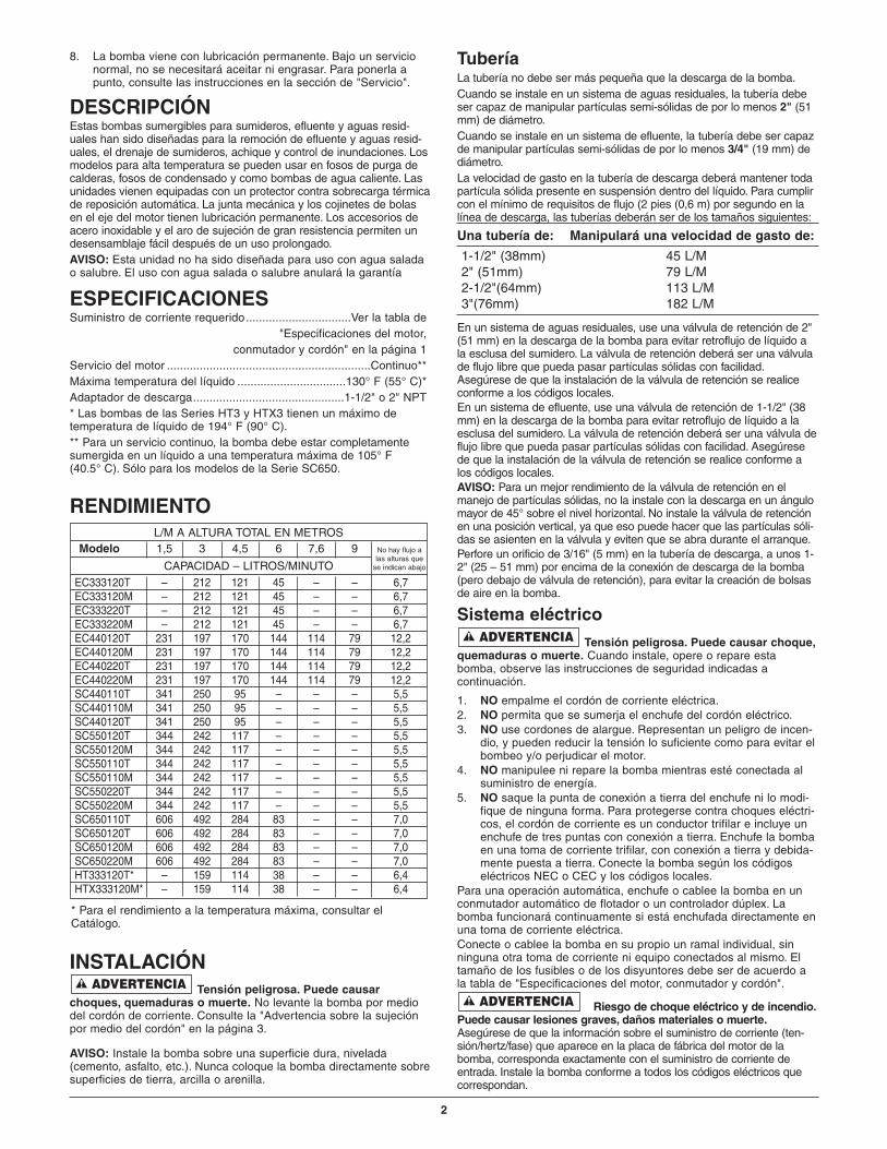
L/M A ALTURA TOTAL EN METROSModelo 1,5 3 4,5 6 7,6 9
CAPACIDAD – LITROS/MINUTOEC333120T – 212 121 45 – – 6,7EC333120M – 212 121 45 – – 6,7EC333220T – 212 121 45 – – 6,7EC333220M – 212 121 45 – – 6,7EC440120T 231 197 170 144 114 79 12,2EC440120M 231 197 170 144 114 79 12,2EC440220T 231 197 170 144 114 79 12,2EC440220M 231 197 170 144 114 79 12,2SC440110T 341 250 95 – – – 5,5SC440110M 341 250 95 – – – 5,5SC440120T 341 250 95 – – – 5,5SC550120T 344 242 117 – – – 5,5SC550120M 344 242 117 – – – 5,5SC550110T 344 242 117 – – – 5,5SC550110M 344 242 117 – – – 5,5SC550220T 344 242 117 – – – 5,5SC550220M 344 242 117 – – – 5,5SC650110T 606 492 284 83 – – 7,0SC650120T 606 492 284 83 – – 7,0SC650120M 606 492 284 83 – – 7,0SC650220M 606 492 284 83 – – 7,0HT333120T* – 159 114 38 – – 6,4HTX333120M* – 159 114 38 – – 6,4
No hay flujo alas alturas que
se indican abajo
* Para el rendimiento a la temperatura máxima, consultar elCatálogo.
RENDIMIENTO

OPERACIÓNRiesgo de incendio o de explosión.
Puede causar lesiones graves, daños materiales o muerte. Nose debe usar en atmósferas explosivas. Esta bomba se debe utilizarsolamente para bombear agua.AVISO: No permita que la bomba marche en un sumidero seco, yaque invalidará la garantía y podrá perjudicar a la bomba.Un protector automático de sobrecarga en el motor protegerá almotor para que no se queme debido a recalentamiento o sobrecar-ga. Cuando el motor se enfríe, el protector de sobrecarga se reposi-cionará automáticamente y arrancará el motor.Si la sobrecarga se dispara con frecuencia, verifique cuál es lacausa. Podría ser un impulsor atascado, tensión baja o inadecuada,o una falla eléctrica en el motor. Si se sospecha que la razón es unafalla eléctrica en el motor, llame a una persona calificada parareparaciones.La bomba viene lubricada en forma permanente. No se necesitaaceitar ni engrasar.
SERVICIOGeneralidades
Tensión peligrosa y riesgo de daños alcordón. Puede causar choques, quemaduras o muerte. Antes desacar la bomba de la esclusa para mantenimiento o reparaciones,siempre desconecte la corriente eléctrica a la bomba y al conmuta-dor de control. No levante la bomba por medio del cordón eléctrico.Consulte la "Advertencia sobre la sujeción por medio del cordón"que aparece a continuación.Después de sacar la cubierta de la esclusa y la tubería de descarganecesaria, levante y saque la bomba fuera de la esclusa.Coloque la bomba en una zona en donde se pueda limpiar bien. Saquetoda oxidación y depósitos que se hayan acumulado en la bomba.Sumerja toda la bomba en una solución desinfectante (clorox o lejía concloro) por lo menos durante una hora antes de desarmar la bomba.La caja del motor de la bomba contiene un aceite especial de lubri-cación que se debe mantener limpio y sin agua en todo momento.AVISO: Siempre que se saque la caja del motor para mantenimientoo reparaciones, saque también el aceite y cámbielo por un aceitenuevo cuando vuelva a armar el motor. Use solamente el tipo deaceite indicado en la lista de repuestos en este manual. Cuando rel-lene con aceite nuevo NO llene demasiado. Siempre permita quequede un espacio de aire de 7/8" (22 mm) desde la parte superiordel lomo de la caja para que el aceite se pueda expandir cuando labomba esté en funcionamiento.
Desensamblaje de la bombaCambio del impulsor y de la juntaA. Cambio del impulsor (Consulte el dibujo de desensamblaje
correcto en la "Tabla de números de referencia del modelo", enla página 4):
1. Saque el tapón de relleno de aceite e invierta la bomba paradrenar el aceite.
2. Saque los tornillos prisioneros que sostienen la caja superiordel motor a la caja inferior del motor; levante y saque la cajasuperior del motor y retire los hilos conductores del motordel conector para desprender la caja superior de la unidad.Los hilos conductores están equipados con bornes deconexión rápida para este fin.
3. Saque los tornillos prisioneros que sostienen la caja inferior delmotor a la voluta; levante y saque la caja inferior del motor.
4. Sostenga la unidad del eje de rotor y destornille el impulsorhaciéndolo girar en la dirección opuesta a las agujas delreloj. Saque el impulsor y límpielo.Si no se requiere ningún otro tipo de servicio, invierta lasinstrucciones que preceden, para volver a armar la bomba.Vuelva a conectar los hilos conectores del motor según seilustra en la Figura 1, llene con aceite dieléctrico limpio(Repuesto No. U197-8A), verifique el nivel del aceite y vuel-va a colocar el tapón de relleno. El aceite debe cubrir eldevanado del motor (Serie E3/EC3/SC5) o la parte superiordel motor (Serie EC4).
B. Cambio de la junta de estancamiento del eje1. Siga las instrucciones que preceden para la remoción del
impulsor.2. Saque los tornillos prisioneros del estator y los espaciadores
(si corresponde). Levante y saque el estator.3. Saque el asiento de cerámica de la junta de estancamiento
del eje y golpetee el cuerpo de la junta para sacarla de lacaja inferior del motor.
4. Limpie bien la cavidad de estancamiento antes de instalar lanueva junta. ¡AVISO! Asegúrese de que las caras de la juntaestén limpias; no raye ni dañe la cara de la nueva juntadurante el cambio. Aplique Permatex #2 o un producto equiv-alente con moderación en el borde exterior del cuerpo de lajunta antes de instalarla en la caja inferior del motor.
5. Presione el cuerpo de la nueva junta en la posición correctadentro de la cavidad de la caja inferior.
6. Presione el asiento de cerámica en el eje del motor. Elimpulsor lo forzará en la posición correcta.
7. Vuelva a armar el estator y apriete los tornillos prisionerosdel estator. Si su bomba tiene un capacitor (Clave No. 14),asegúrese de que el espaciador se encuentre debajo delmismo para mantenerlo lejos del aceite en el motor.
Riesgo de choque eléctrico. Puedecausar quemaduras o muerte. Descargue el capacitor antesde manipularlo. El choque eléctrico puede quemar o matar.
8. Vuelva a armar el impulsor y la bomba (invierta las instruc-ciones del 1 al 4 en la sección A).
9. Instale el nuevo capacitor.10. Vuelva a conectar los hilos conductores del motor según se
ilustra en la Figura 1.11. Llene con aceite dieléctrico limpio (Repuesto No. U197-8A),
verifique el nivel del aceite y vuelva a colocar el tapón de relleno de aceite.
ADVERTENCIA
ADVERTENCIA
ADVERTENCIA
409 0893
Figura 1
3
Hilo verde (conectadoentre los dos divisoresmás altos)
Uno de los hilos negros
Divisor corto
Uno de los hilos negros
VISTA A-A
1. Si se trata de levantar o sostener la bombapor medio del cordón de corriente, se puededañar el cordón y sus conexiones.
2. El cordón se puede dividir, dejando expuestoslos hilos desnudos y la posibilidad de incen-dios o choques eléctricos.
3. Si la bomba se levanta o se sostiene pormedio del cordón de corriente, la garantíaquedará inválida.
4. Use el aro o mango de sujeción en la partesuperior de la bomba para levantarla o bajar-la. Desconecte la corriente a la bomba antesde realizar trabajos en la bomba o de tratar desacarla del sumidero.
Riesgo de choque eléctrico.Puede quemar o matar.No levante la bomba pormedio del cordón de corriente.
ADVERTENCIA SOBRE LA UTILIZACIÓNDEL CORDÓN PARA LEVANTARADVERTENCIA
4
410 0893
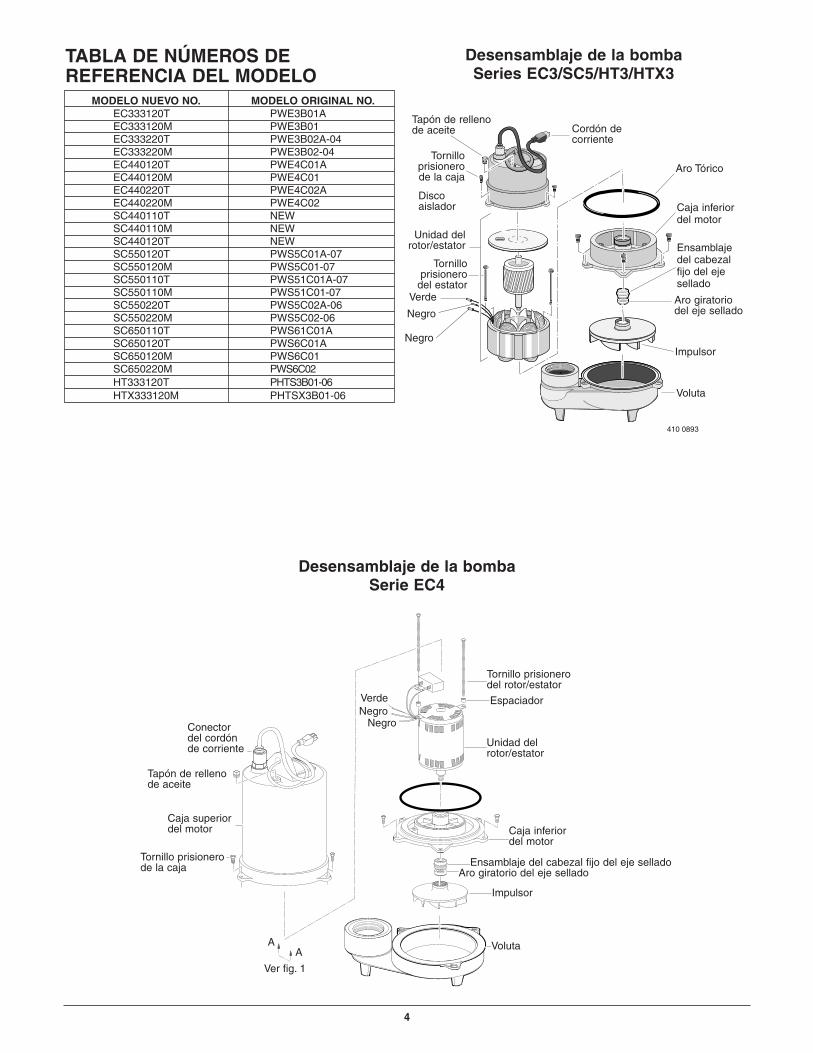
Desensamblaje de la bombaSeries EC3/SC5/HT3/HTX3
Desensamblaje de la bombaSerie EC4
MODELO NUEVO NO. MODELO ORIGINAL NO.EC333120T PWE3B01AEC333120M PWE3B01EC333220T PWE3B02A-04EC333220M PWE3B02-04EC440120T PWE4C01AEC440120M PWE4C01EC440220T PWE4C02AEC440220M PWE4C02SC440110T NEWSC440110M NEWSC440120T NEWSC550120T PWS5C01A-07SC550120M PWS5C01-07SC550110T PWS51C01A-07SC550110M PWS51C01-07SC550220T PWS5C02A-06SC550220M PWS5C02-06SC650110T PWS61C01ASC650120T PWS6C01ASC650120M PWS6C01SC650220M PWS6C02HT333120T PHTS3B01-06HTX333120M PHTSX3B01-06
TABLA DE NÚMEROS DE REFERENCIA DEL MODELO
Voluta
Cordón decorriente
Tapón de rellenode aceite
Tornillo prisionerode la caja
Discoaislador
Negro
Negro
Tornillo prisionero
del estator
Aro Tórico
Caja inferior del motor
Ensamblajedel cabezalfijo del ejesellado
Aro giratorio del eje sellado
Impulsor
Voluta
Tornillo prisionerodel rotor/estator
Espaciador
Unidad delrotor/estator
Caja inferior del motor
Ensamblaje del cabezal fijo del eje selladoAro giratorio del eje sellado
Impulsor
VerdeNegro
NegroConectordel cordónde corriente
Tapón de rellenode aceite
Caja superiordel motor
Ver fig. 1
AA
Tornillo prisionerode la caja
Unidad delrotor/estator
Verde
5
I ll
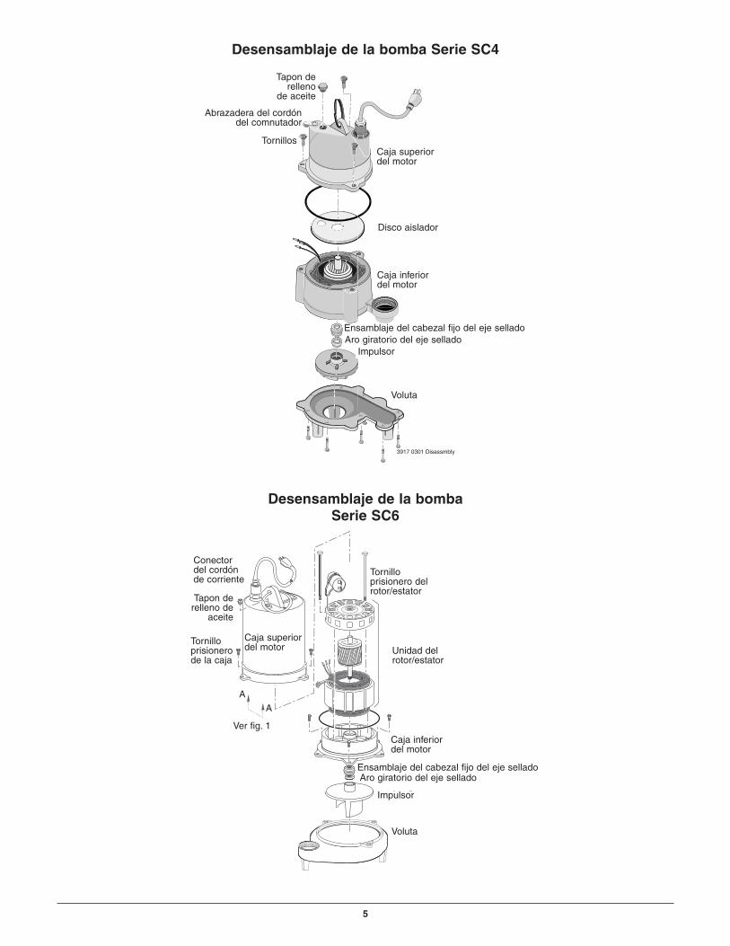
Desensamblaje de la bombaSerie SC6
Voluta
Conectordel cordónde corriente
Tapon derelleno de
aceite
Caja superiordel motor
Tornillo prisionerode la caja
Ver fig. 1
Tornillo prisionero delrotor/estator
Unidad delrotor/estator
Caja inferior del motor
Ensamblaje del cabezal fijo del eje selladoAro giratorio del eje sellado
Impulsor
A
A
3917 0301 Disassmbly
Desensamblaje de la bomba Serie SC4
Voluta
Abrazadera del cordóndel comnutador
Tornillos
Ensamblaje del cabezal fijo del eje selladoAro giratorio del eje sellado
Impulsor
Disco aislador
Caja inferiordel motor
Caja superior del motor
Tapon derelleno
de aceite

6
1
2
4
5
6
7
13
14
6
15A
15B
16
17
3
8
9
10
11
12
VISTA AGRANDADA DE LAS SERIES EC3/SC5/HT3/HTX3
ECC3333120MM ECC333220M SC550110M SC550120MM SSC550220M
Clavee ECC333120T ECC333220T HT333120T HTX333120M SSC550110T SC550120T SSCC550220T
No. Desscripción de laa pieza Cant. 1/3 CV 1115 V 1/3 CCVV 230 VV 1/3 CV 115 V 1/3 CCVV 115 VV 1/2 CCVV 115VV 1//2 CCVV 115V 1/2 CVV 230VV
1 Cordón de corriente 1 PW117-122-TSE PW117-218-TSE PW117-226-TSE § PW117-232-TSE PW117-122-TSE PW117-218-TSE2 Conector del cordón 1 PS17-46P PS17-46P PS17-46P § PS17-46P PS17-46P PS17-46P3 Manija anular 1 U97-128 U97-128 U97-128 U97-128 U97-128 U97-128 U97-1284 Enchufe de 1/4" NPT 1 U78-57DT U78-57DT U78-57DT U78-57DT U78-57DT U78-57DT U78-57DT5 Caja superior del motor 1 PW18-22F PW18-22F PW18-22F PW18-22 PW18-22F PW18-22F PW18-22F6 Tornillo prisionero
#10 – 32 x 3/4" 6 U30-482SS U30-482SS U30-482SS U30-482SS U30-482SS U30-482SS U30-482SS7 Disco aislador 1 PS18-82 PS18-82 PS18-82 PS18-82 PS18-82 PS18-82 PS18-828 Tornillo prisionero
#10 – 32 x 3-1/8" 2 U30-949ZP U30-949ZP U30-949ZP U30-949ZP U30-949ZP U30-949ZP U30-949ZP9 Unidad del rotor/estator 1 PS218-151 — PS218-151 PS218-151 PS218-151 PS218-151 —• Unidad del rotor/ sellado 1 — PS118-151R — — — — PS118-151R• Estator 1 — PS118-153S — — — — PS118-153S
10 Abrazadera del cordón del conmutador * 1 CC0030-13 CC0030-13 CC0030-13 — CC0030-13 CC0030-13 CC0030-13
11 Tornillos prisioneros #8 – 32 x 1/2" 1 U30-539SS U30-539SS U30-539SS — U30-539SS U30-539SS U30-539SS
12 Conmutador automático de flotación * 1 PS17-111 PW217-222 PW217-25 — PS17-109 PS17-111 PW217-222
13 Aro tórico 1 U9-339 U9-339 U9-339 U9-339 U9-339 U9-339 U9-33914 Caja inferior del motor 1 PW18-23AA PW18-23AA PW18-23AA PW18-23AA PW18-23AA PW18-23AA PW18-23AA
15A Ensamblaje del cabezalfijo del eje sellado 1 U9-379A U9-379A U9-379A U9-379A U9-379A U9-379A U9-379A
15B Aro giratorio deleje sellado 1 U9-321A U9-321A U9-321A U9-321A U9-321A U9-321A U9-321A
16 Impulsor 1 PW5-5P PW5-5P PW5-5 PW5-5 PW5-11P PW5-11P PW5-11P17 Voluta 1 PW1-4 PW1-4 PW1-4 PW1-4 PW1-13 PW1-13 PW1-13• Aceite dieléctrico 1 U197-8A U197-8A U197-8A U197-8A U197-8A U197-8A U197-8A
• No se ilustra.* Solamente para los modelos con sufijo "T".§ Requiere cordón de repuesto, Repuesto No. PW117-106-TSE.
LISTA DE REPUESTOS PARA REPARACIONES
7
7
14
8
9
10
11
16A
12
13
4
3
2
1
6
5
16B
17
18
15
9
1050 0797 EC4
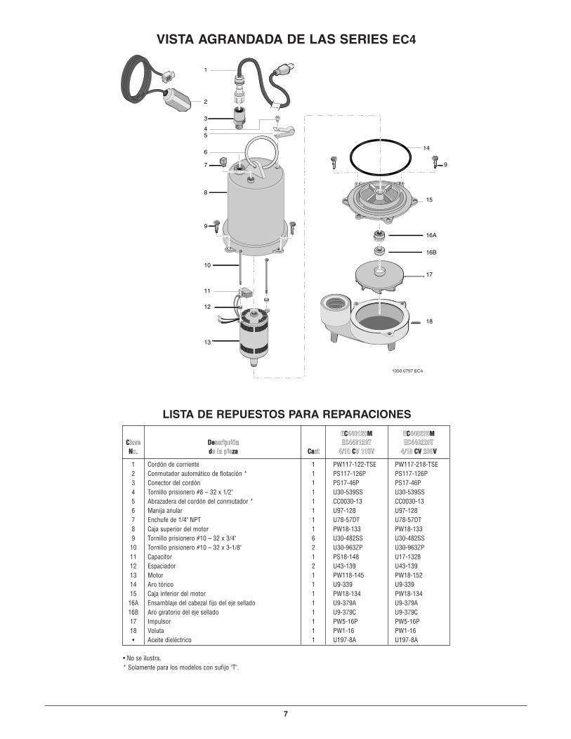
VISTA AGRANDADA DE LAS SERIES EC4
ECC440120MM ECC440220MMCClave DDeescripción EC440120T EC440220TNNo. dde la piezzaa CCaant 4/10 CCV 115V 4/10 CCVV 230VV
1 Cordón de corriente 1 PW117-122-TSE PW117-218-TSE2 Conmutador automático de flotación * 1 PS117-126P PS117-126P3 Conector del cordón 1 PS17-46P PS17-46P4 Tornillo prisionero #8 – 32 x 1/2" 1 U30-539SS U30-539SS5 Abrazadera del cordón del conmutador * 1 CC0030-13 CC0030-136 Manija anular 1 U97-128 U97-1287 Enchufe de 1/4" NPT 1 U78-57DT U78-57DT8 Caja superior del motor 1 PW18-133 PW18-1339 Tornillo prisionero #10 – 32 x 3/4" 6 U30-482SS U30-482SS
10 Tornillo prisionero #10 – 32 x 3-1/8" 2 U30-963ZP U30-963ZP11 Capacitor 1 PS18-148 U17-132812 Espaciador 2 U43-139 U43-13913 Motor 1 PW118-145 PW18-15214 Aro tórico 1 U9-339 U9-33915 Caja inferior del motor 1 PW18-134 PW18-134
16A Ensamblaje del cabezal fijo del eje sellado 1 U9-379A U9-379A16B Aro giratorio del eje sellado 1 U9-379C U9-379C17 Impulsor 1 PW5-16P PW5-16P18 Voluta 1 PW1-16 PW1-16• Aceite dieléctrico 1 U197-8A U197-8A
• No se ilustra.* Solamente para los modelos con sufijo "T".
LISTA DE REPUESTOS PARA REPARACIONES

8
VISTA AGRANDADA DE LAS SERIES SC4
9A
1
4
6
8
3
2
7
10
11
12
13
5
1415
17
16
9B
SC440110TCCllaavvee DDesscripción SCC440110MM SCC440120TNNo. de la pieza CCant. 4/10 CCVV 115V 4/10 CV 115V
1 Cordón de corriente 1 PW117-237-TSE PW117-122-TSE2 Conector del cordón 1 PS17-46P PS17-46P3 Aro tórico 1 U9-370 U9-3704 Tornillo prisionero #10 – 32 x 3/4" 3 U30-482SS U30-482SS5 Caja superior del motor 1 ** **6 Aro tórico 1 U9-339 U9-3397 Disco aislador 1 PS18-82 PS18-828 Caja inferior del motor 1 ** **
9A Ensamblaje del cabezal fijo del eje sellado 1 U9-379A U9-379A9B Aro giratorio del eje sellado 1 U9-321A U9-321A10 Impulsor 1 PW5-11P PW5-11P11 Voluta 1 PW1-13 PW1-1312 Tornillo prisionero #10 – 32 x 3-1/8" 8 U30-966SS U30-966SS13 Conmutador automático de flotación* 1 PS17-109 PS17-11114 Manija anular 1 U97-128 U97-12815 Enchufe de 1/4" NPT 1 U78-941ZPV U78-941ZPV16 Tornillo prisionero #8 – 32 x 1/2" 1 U30-539SS U30-539SS17 Abrazadera del cordón del conmutador* 1 CC0030-13 CC0030-13• Aceite dieléctrico (usan .61 qts.) 1 U197-8A U197-8A
• No se ilustra.* Solamente para los modelos con sufijo "T".** Si el motor falla, cambie toda la bomba.
LISTA DE REPUESTOS PARA REPARACIONES

9
1
2
3
8
6
9
4
6
16
11
12
15A
15B
14
3310 0898 SC6
513
17
18
10
7
VISTA AGRANDADA DE LA SERIE SC6
SSCC66550120T-02Clavve SSCC65501110T-02 SSCC650120M-02 SSCC650220M-02No. DDescripción de la piezza Cant. 1/2 CV 1115V 11/2 CCVV 11155V 1/2 CV 230V
1 Cordón de corriente 1 PW117-237-TSE PW117-122-TSE PW117-218-TSE2 Conector del cordón 1 PS17-46P PS17-46P PS17-46P3 Enchufe de 1/4" NPT 1 U78-57DT U78-57DT U78-57DT4 Manija anular 1 U97-128 U97-128 U97-1285 Caja superior del motor 1 PW18-133 PW18-133 PW18-1336 Tornillo prisionero #10 – 32 x 3/4" 6 U30-482SS U30-482SS U30-482SS7 Capacitor 1 U80-1590 U80-1590 U80-15908 Tornillo prisionero #10 – 32 x 4-1/4" 2 U30-973ZP U30-973ZP U30-973ZP9 Arandela 1 U43-43ZP U43-43ZP U43-43ZP10 Unidad del rotor/estator 1 PW218-148 PW218-148 PW218-14911 Tornillo prisionero #8 – 32 x 1/2" 1 U30-539SS U30-539SS U30-539SS12 Abrazadera del cordón del conmutador * 1 CC0030-13 CC0030-13 –13 Aro tórico 1 U9-339 U9-339 U9-33914 Caja inferior del motor 1 PW18-23AA PW18-23AA PW18-23AA
15A Sello del eje, asiento estacionario 1 U9-439A U9-439A U9-439A15B Sello del eje, asiento giratorio 1 U9-439B U9-439B U9-439B16 Impulsor 1 PW5-21 PW5-21 PW5-2117 Voluta 1 PW1-18 PW1-18 PW1-1818 Conmutador automático de flotación * 1 PS17-109 PS17-111 –• Aceite dieléctrico ** U197-8A U197-8A U197-8A
• No se ilustra. * Solamente para los modelos con sufijo "T".
** La Serie SC6 usa menos de 2 cuartos.
LISTA DE REPUESTOS PARA REPARACIONES

PROBLEMAS – SOLUCIONES Arranques repentinos. Si la corriente a la bomba está activada cuando se reposicione la sobrecarga térmica,
es posible que la bomba arranque sin advertencia alguna. Si está trabajando en la bomba, existe el peligro de choques eléctricos ode que el impulsor atrape sus dedos o sus herramientas. Desconecte la corriente antes de realizar reparaciones en la bomba.
ADVERTENCIA
10
A. La bomba no funciona: 1. Verifique que el cordón de corriente esté bien enchufado en la toma de corriente ocableado firmemente en el controlador o la caja de conmutación. Desconecte la corriente hacia la toma de corriente antes de manipular la bomba o el motor.
2. Verifique que haya corriente eléctrica.3. Verifique el nivel del fluido líquido sea suficiente para activar el conmutador
o el controlador.4. Verifique que haya un orificio de ventilación de 3/16" (5 mm) en la tubería de
descarga y que no esté tapado.5. Verifique que no hayan bloqueos en la admisión de la bomba, en el impulsor, en la
válvula de retención o en la tubería de descarga.6. Desconecte la bomba de la fuente de energía por lo menos durante 30 minutos
para permitir que el motor se enfríe, y para protegerse contra arranques repentinos.Consulte la Advertencia que aparece arriba. Verifique la causa del recalentamiento.La bomba está marchando en seco debido a que el conmutador de flotación se atascó con algo. La tubería de admisión está tapada. La tubería de salida está tapada.
B. La bomba no logra vaciar 1. Asegúrese de que todas las válvulas en la tubería de descarga estén totalmente el sumidero: abiertas.
2. Limpie la tubería de descarga y la válvula de retención3. Verifique que no hayan bloqueos en la admisión de la bomba o en el impulsor.4. El tamaño de la bomba no es adecuado. Es posible que se requiera una bomba
de mayor capacidad.
C. La bomba no se apaga: 1. Verifique que los flotadores automáticos del conmutador o del controlador estén funcionando y se encuentren ubicados correctamente. Consulte las instrucciones de la instalación del conmutador/controlador.
2. Si la bomba no funciona de ninguna manera o continúa funcionando mal, consulte a su técnico de reparaciones local.
GARANTÍA LIMITADASTA-RITE le garantiza al comprador/consumidor original (“Comprador” o “Usted”) de los productos enumerados abajo, que estos estarán libres dedefectos en material y mano de obra durante el Período de Garantía indicado a continuación.
Producto Período de Garantía
Productos de sistemas de agua — bombas de chorro, lo que ocurra primero:pequeñas bombas centrífugas, bombas sumergibles 12 meses desde la fecha de la instalación inicial, o y acceso-rios asociados 18 meses desde la fecha de fabricación
Tanques de devanado de fibra de vidrio 5 años desde la fecha de la instalación inicialSignature 2000®
Tanques de devanado de fibra de vidrio Pro-SourceMC 5 años desde la fecha de la instalación inicial
Tanques a presión de acero Pro-SourceMC 5 años desde la fecha de la instalación inicial
Tanques con revestimiento epoxídico Pro-SourceMC 3 años desde la fecha de la instalación inicial
Productos para sumideros/aguas residuales/efluente 12 meses desde la fecha de la instalación inicial, o18 meses desde la fecha de fabricación
Nuestra garantía no se aplicará a ningún producto que, a nuestro sólo juicio, haya sido sometido a negligencia, mal uso, instalación inadecuada omal mantenimiento. Sin prejuicio a lo que antecede, la garantía quedará anulada en el caso en que un motor trifásico se haya usado con una fuentede alimentación monofásica, a través de un convertidor de fase. Es importante indicador que los motores trifásicos deben estar protegidos por relésde sobrecarga de disparo extra-rápido, con compensación ambiental de tres etapas, del tamaño recomendado, de lo contrario, la garantía quedaráanulada.
Su único recurso, y la única obligación de STA-RITE es que STA-RITE repare o reemplace los productos defectuosos (a juicio de STA-RITE). Usteddeberá pagar todos los cargos de mano de obra y de envío asociados con esta garantía y deberá solicitar el servicio bajo garantía a través del con-cesionario instalador tan pronto como se descubra un problema. No se aceptará ninguna solicitud de servicio bajo garantía que se reciba despuésdel vencimiento del Período de Garantía. Esta garantía no se puede transferir.
STA-RITE NO SE HARÁ RESPONSABLE DE NINGÚN DAÑO CONSECUENTE, INCIDENTAL O CONTINGENTE.
LAS GARANTÍAS QUE ANTECEDEN SON EXCLUSIVAS Y EN LUGAR DE TODA OTRA GARANTÍA EXPLÍCITA O IMPLÍCITA, INCLUYENDOPERO SIN LIMITARSE A LAS GARANTÍAS IMPLÍCITAS DE COMERCIABILIDAD E IDONEIDAD PARA UN FIN ESPECÍFICO. LAS GARANTÍASQUE ANTECEDEN NO SE EXTENDERÁN MÁS ALLÁ DE LA DURACIÓN EXPRESAMENTE SUMINISTRADA EN LA PRESENTE.
Algunos estados no permiten la exclusión o limitación de daños incidentales o consecuentes o de limitaciones de tiempo sobre garantías implícitas,de modo que es posible que las limitaciones o exclusiones que preceden no correspondan en su caso. Esta garantía le otorga derechos legalesespecíficos y es posible que usted también tenga otros derechos que pueden variar de un estado al otro.
Esta garantía reemplaza toda garantía publicada anteriormente.
STA-RITE INDUSTRIES293 Wright St., Delavan, WI 53115