Embed Size (px)
Citation preview

8/13/2019 28 Mixed Matrix Membranes (MMMs) Comprising Organic Polymers With Dispersed Inorganic Fillers for Gas Separa…
http://slidepdf.com/reader/full/28-mixed-matrix-membranes-mmms-comprising-organic-polymers-with-dispersed 1/25
Prog. Polym. Sci. 32 (2007) 483–507
Mixed matrix membranes (MMMs) comprising organicpolymers with dispersed inorganic fillers for gas separation
Tai-Shung Chunga,, Lan Ying Jianga, Yi Lia, Santi Kulprathipanjab
aDepartment of Chemical and Biomolecular Engineering, National University of Singapore, 10 Kent Ridge Crescent,
Singapore 119260, SingaporebUOP LLC, 50 East Algonquin Road, Des Plaines, IL 60017-5016, USA
Received 16 September 2006; received in revised form 3 January 2007; accepted 16 January 2007
Available online 12 February 2007
Abstract
Gas separation by selective transport through polymeric membranes is one of the fastest growing branches of membrane
technology. However, the existing polymeric membrane materials are inadequate to fully exploit the application
opportunities on industrial scale; the improvement in permeability is at the expense of selectivity, and vice versa. A new
type of membrane material emerging with the potential for future applications is mixed matrix materials composed of
homogeneously interpenetrating polymeric and inorganic particle matrices. Compared to original polymeric membranes,
significant improvement in separation properties with trivial loss in membrane flexibility is expected for the resultant mixed
matrix membranes (MMMs). This review first gives an outline of the concept and the key advances of MMMs.
Subsequently, recent developments are presented, including two immediate challenges: achieving an optimized interface
structure, and forming asymmetric or composite membrane with an ultrathin and defect-free mixed matrix skin. Attractive
avenues to overcome these challenges are emphasized. The review of the Maxwell model demonstrates how the transport
properties of MMMs are related to the polymer matrix, molecular sieves, as well as membrane morphology. Finally, future
directions of MMMs’ fabrication and application are suggested.
r 2007 Elsevier Ltd. All rights reserved.
Keywords: Mixed matrix membranes (MMMs); Gas separation; Membrane fabrication
Contents
1. Introduction . . . . . . . . . . . . . . . . . . . . . . . . . . . . . . . . . . . . . . . . . . . . . . . . . . . . . . . . . . . . . . . . . . . . . 4842. Concept of mixed matrix membranes (MMMs) . . . . . . . . . . . . . . . . . . . . . . . . . . . . . . . . . . . . . . . . . . . . 485
ARTICLE IN PRESS
www.elsevier.com/locate/ppolysci
0079-6700/$- see front matterr 2007 Elsevier Ltd. All rights reserved.
doi:10.1016/j.progpolymsci.2007.01.008
Abbreviations: ABS, acrylonitrile–butadiene–styrene; CA, cellulose acetate; EPDM, ethylene propylene rubber; NBR, nitrile butadiene
rubbers; PC, bisphenol-A polycarbonate; PCP, polychloroprene; PEI, polyetherimide; PES, polyethersulfone; PI, polyimide; PMP, poly
(4-methyl-2-pentyne); PTMSP, poly (1-trimethylsilyl-1-propyne); PSf, polysulfone; PVAc, polyvinyl acetate; TMHFPSf, tetramethyl
hexafluoro polysulfone; 6FDA-IPDA, poly (hexafluoro dianhydride isopropylidene dianiline); 6FDA-MDA, poly (hexafluoro dianhydride
methylene dianiline); 6FDA-6FpDA, poly (hexafluoro dianhydride 4, 40-hexafluoro diamine); 6FDA-6FmDA; poly (hexafluoro
dianhydride 3, 30-hexafluoro diamine)Corresponding author. Fax: +65 6779 1936
E-mail address: [email protected] (T.-S. Chung).

8/13/2019 28 Mixed Matrix Membranes (MMMs) Comprising Organic Polymers With Dispersed Inorganic Fillers for Gas Separa…
http://slidepdf.com/reader/full/28-mixed-matrix-membranes-mmms-comprising-organic-polymers-with-dispersed 2/25
3. Molecular design and key advances on MMMs . . . . . . . . . . . . . . . . . . . . . . . . . . . . . . . . . . . . . . . . . . . . 486
3.1. Conventional MMMs . . . . . . . . . . . . . . . . . . . . . . . . . . . . . . . . . . . . . . . . . . . . . . . . . . . . . . . . . . 486
3.2. Unconventional MMMs . . . . . . . . . . . . . . . . . . . . . . . . . . . . . . . . . . . . . . . . . . . . . . . . . . . . . . . . 487
4. Flat dense MMMs. . . . . . . . . . . . . . . . . . . . . . . . . . . . . . . . . . . . . . . . . . . . . . . . . . . . . . . . . . . . . . . . . 489
4.1. Recent progress . . . . . . . . . . . . . . . . . . . . . . . . . . . . . . . . . . . . . . . . . . . . . . . . . . . . . . . . . . . . . . 489
4.2. Variables tailoring MMMs’ performance. . . . . . . . . . . . . . . . . . . . . . . . . . . . . . . . . . . . . . . . . . . . . 490
4.2.1. Suitable combination of polymer/inorganic filler . . . . . . . . . . . . . . . . . . . . . . . . . . . . . . . . . . 4904.2.2. Particles size. . . . . . . . . . . . . . . . . . . . . . . . . . . . . . . . . . . . . . . . . . . . . . . . . . . . . . . . . . . . 493
4.2.3. Particle sedimentation and agglomeration . . . . . . . . . . . . . . . . . . . . . . . . . . . . . . . . . . . . . . . 493
4.2.4. Interface morphologies . . . . . . . . . . . . . . . . . . . . . . . . . . . . . . . . . . . . . . . . . . . . . . . . . . . . 494
4.3. Optimization of interface morphology. . . . . . . . . . . . . . . . . . . . . . . . . . . . . . . . . . . . . . . . . . . . . . . 495
4.3.1. Interface voids . . . . . . . . . . . . . . . . . . . . . . . . . . . . . . . . . . . . . . . . . . . . . . . . . . . . . . . . . . 495
4.3.2. Pore blockage and chain rigidification . . . . . . . . . . . . . . . . . . . . . . . . . . . . . . . . . . . . . . . . . 496
5. Asymmetric and composite MMMs . . . . . . . . . . . . . . . . . . . . . . . . . . . . . . . . . . . . . . . . . . . . . . . . . . . . 497
5.1. Flat sheet asymmetric MMMs . . . . . . . . . . . . . . . . . . . . . . . . . . . . . . . . . . . . . . . . . . . . . . . . . . . . 498
5.2. Hollow fiber asymmetric MMMs . . . . . . . . . . . . . . . . . . . . . . . . . . . . . . . . . . . . . . . . . . . . . . . . . . 498
5.2.1. Hollow fiber asymmetric MMMs by single-layer spinning . . . . . . . . . . . . . . . . . . . . . . . . . . . 498
5.2.2. Hollow fiber asymmetric MMMs by dual-layer spinning . . . . . . . . . . . . . . . . . . . . . . . . . . . . 498
5.2.3. Particle distribution control in hollow fibers . . . . . . . . . . . . . . . . . . . . . . . . . . . . . . . . . . . . . 5006. Modified Maxwell model for performance prediction of MMMs . . . . . . . . . . . . . . . . . . . . . . . . . . . . . . . . 501
7. Conclusions and perspective . . . . . . . . . . . . . . . . . . . . . . . . . . . . . . . . . . . . . . . . . . . . . . . . . . . . . . . . . . 502
Acknowledgements . . . . . . . . . . . . . . . . . . . . . . . . . . . . . . . . . . . . . . . . . . . . . . . . . . . . . . . . . . . . . . . . 504
References . . . . . . . . . . . . . . . . . . . . . . . . . . . . . . . . . . . . . . . . . . . . . . . . . . . . . . . . . . . . . . . . . . . . . . 504
1. Introduction
The separation of gases by membranes is a
dynamic and rapidly growing field [1,2]. In mem-
brane-based gas separation process, components areseparated from their mixtures by differential per-
meation through membranes. A number of advan-
tages, including low capital and operating costs,
lower energy requirements and, generally, ease of
operation are offered by membrane separation
[3–8]. As a result, gas separation by membrane
process has acquired great significance in the
industrial scenario in terms of economical consid-
erations, as gases occupy a central position in the
chemical feed stock industry. Current applications
of membrane-based gas separation include oxygen
and nitrogen enrichment, hydrogen recovery, nat-
ural gas separation and the removal of volatile
organic compounds from effluent streams [9,10].
The ‘‘heart’’ of a membrane process is the
membrane itself. To fully exploit the growing
opportunities in the field of gas separation, strong
interest exists in the identification of new membrane
materials that can comply with current require-
ments [7]. Criteria for selecting membrane materials
for a given separation are complex. Generally,
durability, mechanical integrity at the operating
conditions, productivity and separation efficiency
are important stipulations [6]. Of these require-
ments, selectivity and permeation rate are the most
basic ones. High selectivity and permeability render
the operation parameters more flexible (e.g., lower
driving force and smaller membrane area to achievea given separation); therefore, a more efficient
separation process results.
In the area of membrane-based gas separation,
non-porous polymeric membranes based on solu-
tion-diffusion mechanism have been exclusively
employed in current commercial devices [11–13].
Typically, polymers have the advantages of desir-
able mechanical properties and economical proces-
sing capabilities. According to the solution-
diffusion model, the permeation of molecules
through membranes is controlled by two major
parameters: diffusivity coefficient (D) and solubility
coefficient (S ). The diffusivity is a measure of the
mobility of individual molecule passing through the
voids between the polymeric chains in a membrane
material. The solubility coefficient equals the ratio
of the dissolved penetrant concentration in the
upstream face of the polymer to the upstream
penetrant partial pressure. The permeability (P )
representing the ability of molecules to pass through
a membrane is defined as
P ¼ DS . (1)
ARTICLE IN PRESS
T.-S. Chung et al. / Prog. Polym. Sci. 32 (2007) 483–507 484
8/13/2019 28 Mixed Matrix Membranes (MMMs) Comprising Organic Polymers With Dispersed Inorganic Fillers for Gas Separa…
http://slidepdf.com/reader/full/28-mixed-matrix-membranes-mmms-comprising-organic-polymers-with-dispersed 3/25
The ability of a membrane to separate two
molecules, for example, A and B , is the ratio of
their permeabilities, called the membrane selectivity,
aAB ¼ P A=P B . (2)
Since P is the product of D and S , Eq. (2) may berewritten as
aAB ¼ ðDA=DB Þ ðS A=S B Þ. (3)
Therefore, the difference in permeability is
resulted not only from diffusivity (mobility) differ-
ence of the various gas species, but also from
difference in the physicochemical interactions of
these species with the polymer that determine the
amount that can be accommodated per unit volume
of the polymer matrix [13,14]. The balance between
the solubility selectivity and the diffusivity selectiv-
ity determines the selective transport of the compo-nent in a feed mixture. Much fundamental research
related to the development of polymers with
improved gas separation properties focuses on
manipulation of penetrant diffusion coefficient via
systematic modification of polymer chemical struc-
ture or superstructure and either chemical or
thermal post-treatment of polymeric membranes
[15–22]. Solubility selectivity may also be increased
by modifying polymer structure to increase the
solubility of one component in a mixture or adding
special agents which can complex with a desiredpenetrant in a mixture [13,23].
Inorganic membranes are usually formed from
metals, ceramics, or pyrolyzed carbon [24]. These
membranes are increasingly being explored to
separate gas mixtures due to the well-known
thermal and chemical stabilities and much higher
gas fluxes or selectivities as compared to polymeric
membranes. Inorganic molecular sieves like zeolites
and carbon molecular sieves are excellent materials
with diffusivity selectivity significantly higher than
polymeric materials. The accurate size and shape
discrimination resulting from the narrow pore
distribution ensures superior selectivity [25]. Micro-
porous inorganic materials have also been modified
to achieve solubility-based separation; in these
materials, surface flow and capillary condensation
play important roles in increasing the flow of larger
species [26]. Early inorganic membranes were
developed about 50 years ago [27]. Corning glass
developed a homogeneous porous glass (Vycor)
with 20–40 A ˚ pores in the 1940s. Also in the 1940s,
membranes were developed by the Manhattan
Project to enrich uranium by separating uranium
isotopes as UF6. This was the first-large scale gas
separation process using inorganic membranes.
Membranes of various zeolites with large-pore (Y -
type [28], X [29], b [30]), medium-pore (ZSM-5 [31],
FER [32]), and small-pore (A-type [33], SAPO-34
[34]) are used for gas separation. Some of themembranes have good selectivity. Carbon molecular
sieve membranes (CMSMs) are produced by carbo-
nization of a suitable polymeric membrane pre-
cursor under controlled conditions. Excellent
separation properties of CMSMs have been re-
ported for separation of gas mixtures like natural
gas, hydrocarbons, and air [35–37].
2. Concept of mixed matrix membranes (MMMs)
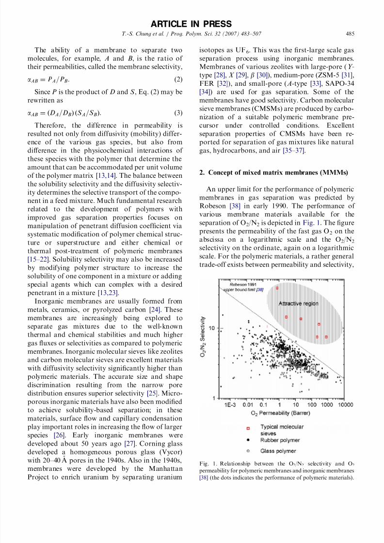
An upper limit for the performance of polymericmembranes in gas separation was predicted by
Robeson [38] in early 1990. The performance of
various membrane materials available for the
separation of O2/N2 is depicted in Fig. 1. The figure
presents the permeability of the fast gas O2 on the
abscissa on a logarithmic scale and the O2/N2
selectivity on the ordinate, again on a logarithmic
scale. For the polymeric materials, a rather general
trade-off exists between permeability and selectivity,
ARTICLE IN PRESS
Fig. 1. Relationship between the O2/N2 selectivity and O2
permeability for polymeric membranes and inorganic membranes
[38] (the dots indicates the performance of polymeric materials).
T.-S. Chung et al. / Prog. Polym. Sci. 32 (2007) 483–507 485

8/13/2019 28 Mixed Matrix Membranes (MMMs) Comprising Organic Polymers With Dispersed Inorganic Fillers for Gas Separa…
http://slidepdf.com/reader/full/28-mixed-matrix-membranes-mmms-comprising-organic-polymers-with-dispersed 4/25
with an ‘‘upper-bound’’ evident in Fig. 1. When
materials with separation properties near this limit
were modified based on the traditional structure–
property relation, the resultant polymers have
permeability and selectivity tracking along this line
instead of exceeding it. On the other hand, as maybe seen in Fig. 1, the inorganic materials have
properties lying far beyond the upper-bound limit
for the organic polymers [39–43]. Though tremen-
dous improvements had been achieved in tailoring
polymer structure to enhance separation properties
during the last two decades, further progress
exceeding the trade-off line seems to present a
severe challenge in the near future. Similarly, the
immediate application of inorganic membranes is
still seriously hindered by the lack of technology to
form continuous and defect-free membranes, the
extremely high cost for the membrane production,and handling issues (e.g., inherent brittleness)
[44,45]. In view of this situation, a new approach
is needed to provide an alternate and cost-effective
membrane with separation properties well above
the upper-bound limit between permeability and
selectivity.
The latest membrane morphology emerging with
the potential for future applications involves
MMM, consisting of organic polymer and inorganic
particle phases, as shown schematically in Fig. 2.
The bulk phase (phase A) is typically a polymer; thedispersed phase (phase B) represents the inorganic
particles, which may be zeolite, carbon molecular
sieves, or nano-size particles. MMMs have the
potential to achieve higher selectivity, permeability,
or both relative to the existing polymeric mem-
branes, resulting from the addition of the inorganic
particles with their inherent superior separation
characteristics. At the same time, the fragility
inherent in the inorganic membranes may be
avoided by using a flexible polymer as the contin-
uous matrix.
The investigation of MMMs for gas separation
was first reported in 1970s with the discovery of a
delayed diffusion time lag effect for CO2 and CH4
when adding 5A zeolite into rubbery polymer
polydimethyl siloxane (PDMS) [46]. In this work,
Paul and Kemp found that the addition of 5A into
the polymer matrix caused very large increases in
the diffusion time lag but had only minor effects on
the steady-state permeation. Researchers at UOP
were the first to report that that mixed matrixsystems of polymer/adsorbent might yield superior
separation performance to that of pure polymeric
system [47]. They observed an enhanced O2/N2
selectivity from 3.0 to 4.3 when increasing silicalite
content in the polymer cellulose acetate (CA)
matrix. The concept of MMM has been also
demonstrated at UOP LLC in the mid-1980s using
CA/silicalite MMMs for CO2/H2 separation [48]. In
the demonstration, a feed mixture of 50/50 (mol%)
CO2/H2 with a differential pressure of 50 psi was
used. The calculated separation factor for CO2/H2
was found to be 5.1572.2. In contrast, a CO2/H2
separation factor of 0.7770.06 was found for CA
membrane. This indicates that silicalite in the
membrane phase has reversed the selectivity from
H2 to CO2.
3. Molecular design and key advances on MMMs
3.1. Conventional MMMs
Much of the research conducted to date on
MMM has focused on the addition of porousinorganic filler to polymer matrices. The two
materials are required to be selective for the same
gas pairs, and, in most case, the inorganic fillers may
have selectivity far superior to the neat polymer.
Ideally, the incorporation of a small volume
fraction of inorganic fillers into the polymer matrix
can result in a significant increase in overall
separation efficiency, as predicted by the so-called
Maxwell model [49]. This model was originally
derived for the estimation of the dielectric properties
of composite materials [50], but has been widelyaccepted as a simple and effective tool for estimat-
ing MMM properties [49]. The Maxwell model
equation for MMMs with dilute suspension of
spherical particles can be written as follows:
P eff ¼ P cP d þ 2P c 2fd ðP c P d Þ
P d þ 2P c þ fd ðP c P d Þ
, (4)
where P eff is the effective composite membrane
permeability, f the volume fraction, P the single
component permeability and the subscripts d and c
refers to the dispersed and continuous phases,
respectively.
ARTICLE IN PRESS
A. Polymer
phase
B. Inorganic
particle phase
Fig. 2. Schematic of a mixed matrix membrane (MMM).
T.-S. Chung et al. / Prog. Polym. Sci. 32 (2007) 483–507 486

8/13/2019 28 Mixed Matrix Membranes (MMMs) Comprising Organic Polymers With Dispersed Inorganic Fillers for Gas Separa…
http://slidepdf.com/reader/full/28-mixed-matrix-membranes-mmms-comprising-organic-polymers-with-dispersed 5/25
To properly choose the dispersed and continuous
phases, one must take the transport mechanisms
and the gas component preferentially transporting
through the membrane into consideration. In some
cases, it is more sensible to allow the smaller
component to pass through; therefore, inorganicfillers with molecular sieving characteristics and
polymers based on the size selection should be
combined to produce MMMs. On the other hand,
the selective transport of more condensable mole-
cules through the membrane is more economical in
some industrial applications. To fulfill this target,
the MMMs may include microporous media that
favor a selective surface flow mechanism and
polymers that separate the mixtures by solubility
selectivity [26,51–53]. The MMMs thus produced
enable the selective adsorption and/or surface
diffusion of more condensable component, whileexcluding the less condensable component.
Many studies have demonstrated that the re-
markable separation properties of MMMs accord
with this design, exhibiting performance well
beyond the intrinsic properties of the polymer
matrix. The most prominent work involved the
application 4A zeolite [54–56]. This zeolite has pore
a size of 3.8A ˚ and its O2/N2 selectivity at 35 1C is
37, which is much superior to that of glassy
polymers [57]. As for polymers more permeable to
O2, the incorporation of 4A zeolite will certainlyresult in membranes with improved O2 over N2
selectivity. Mahajan et al. prepared MMMs con-
taining 4A zeolite in polymers such as polyvinyl
acetate (PVAc), Ultems polyetherimide (PEI),
Matrimids polyimide (PI) among others. With high
loadings of zeolites in the polymer matrix, the
O2/N2 selectivity for MMMs reached almost twice that
of pure polymer membranes. Table 1 summarizes
the performance of some MMMs developed in this
work. Apparently, there exists only trivial difference
between the predicted and experimental selectivity.Fig. 3 shows their O2/N2 transport properties in
comparison with the Robeson, 1991 O2/N2 upper-
bound limit curve, indicating that MMMs are
promising candidates for the next generation of
membranes. However, Table 1 also indicates that
there is a severe difference in permeability between
the model prediction and the experimental values.
Clearly, the original Maxwell model should be
modified to consider the complexity of MMMs,
and this will be taken up in Section 6.
3.2. Unconventional MMMs
Contrary to the aforementioned MMMs consist-
ing of porous fillers and polymeric matrices with
similar selectivities, a novel MMM design has been
proposed using non-porous nano-size particles
[58–60]. The function of the fillers is to system-
atically manipulate the molecular packing of the
polymer chains, hence enhancing the separation
properties of glassy polymeric membranes. This
approach is partly motivated by the unique trans-
port characteristics of poly (4-methyl-2-pentyne)(PMP), which is a reverse-selective glassy polymer.
Because of inherent chain packing characteristics,
this material has an intrinsically high free volume.
The high free volume reduces the importance of
diffusivity selectivity, so that solubility selectivity
ARTICLE IN PRESS
Table 1
Mixed matrix membrane performancea: predicted vs. observed at 35 1C [54,56]
Polymer Particle loading (vol%) Membranes O2 permeabilityb (barrier) O2/N2c selectivity
— Polymeric 0.5 5.9PVAc [54] 15 vol% loading MMMs 0.45 (0.53) 7.3–7.6 (7.5)
25 vol% loading 0.4 (0.55) 8.3–8.5 (8.7)
40 vol% loading 0.28–0.35 (0.55) 9.7–10.4 (10.9)
Polymer A — Polymeric 0.5 7.1
(2,20-BPDA+BPADA) [54] 20 vol% loading MMMs 0.47 (0.55) 9.4–9.6 (9.4)
30 vol% loading 0.4 (0.57) 10.6–10.8 (10.8)
40 vol% loading 0.37 (0.6) 12.4–12.5 (12.6)
Ultems PEI [56] — Polymeric 0.38 7.8
15 vol% loading MMMs 0.38 (0.42) 9.7 (9.7)
35 vol% loading 0.28(0.49) 12.9 (13.0)
aThe inorganic phase is zeolite 4A.b,cThe data in the parenthesis correspond to Maxwell model prediction.
T.-S. Chung et al. / Prog. Polym. Sci. 32 (2007) 483–507 487

8/13/2019 28 Mixed Matrix Membranes (MMMs) Comprising Organic Polymers With Dispersed Inorganic Fillers for Gas Separa…
http://slidepdf.com/reader/full/28-mixed-matrix-membranes-mmms-comprising-organic-polymers-with-dispersed 6/25
becomes dominant for the overall separation
process. As a result, PMP is more permeable to
hydrocarbons relative to supercritical gases (e.g.,
air, nitrogen or methane). Normally, diffusivity
selectivity is dominant for gas transport in glassy
polymers due to the low mobility of glassy polymer
chains, which leads to a faster transport of smallergas molecules (e.g., H2) than that of larger gas
molecules (e.g., CO2). However, PMP possesses a
high free volume due to its inherent chain packing
characteristics. The high free volume may reduce
the importance of diffusivity selectivity and make
the solubility selectivity dominant for gas transport
in PMP membranes. This change in separation
mechanism can causes condensable gases (e.g., CO2)
to be more permeable in PMP membranes than
non-condensable gases (e.g., H2), an effect called
reverse-selectivity. It is expected that by molecular-
level mixing, the nano-size particles with the
polymer, the accessible free volume in the polymer
matrix might be further increased. The resultant
MMM may have separation properties very similar
to those of microporous carbons, for which selective
surface flow and solubility selectivity prevail [14].
In the work of Merkel et al. [58,60] and He et al.
[59], non-porous, nano-size fumed silica, was
incorporated into a PMP matrix. Compared to the
neat PMP membranes, the selective transport of
n-butane over methane in the gas mixture obtained
with the PMP/fumed silica composite system was
tremendously enhanced in both permeability and
selectivity. The permeability of this filled system
displays a surprising departure from the Maxwell
model prediction. Thus, at 50 wt% fumed silica, the
PMP/fumed silica nanocomposite’s permeability is
more than 240% greater than that of neat PMP,
whereas the Maxwell’s equation predicts a 35%
reduction in permeability at the same filler loading.
As speculated, the addition of fumed silica particles
to PMP has also been confirmed to systemati-
cally increase the average size of the free volume.
Fig. 4 illustrates the inverse trade-off relation-
ship of n-butane/methane selectivity and n-butane
ARTICLE IN PRESS
11
10
O 2 / N 2 S e l e c t i v i t y
O2 Permeability (Barrer)
Ultem ® MMM
PVAc MMM
Polymer A (BPDA-BPADA)
MMM
Robeson 1991
upper bound limit
Traditional
polymeric
membranes
0.2 0.3 0.4 0.5 0.6 0.7 0.8 0.9
Pure polymeric membranes
Mixed matrix membranes(MMMs)
Increasing particle loading
Fig. 3. Mixed matrix membranes performance compared to the Robeson, 1991 upper-bound limit [54,56].
10 100 1000 10000 1000000.1
1
10
100
n - B u t a n e / m e t h a n e s e l e c t i v i t y
n-Butane Permeability (Barrer)
Pure polymeric membranes
Mixed matrix membranes
P-ZH
PTPSDPA
PDMS
PMP
Silica filled PMP
Fig. 4. Mixed gas n-C4H10/CH4 selectivity vs. n-C4H10, perme-
ability for different polymers [59].
T.-S. Chung et al. / Prog. Polym. Sci. 32 (2007) 483–507 488

8/13/2019 28 Mixed Matrix Membranes (MMMs) Comprising Organic Polymers With Dispersed Inorganic Fillers for Gas Separa…
http://slidepdf.com/reader/full/28-mixed-matrix-membranes-mmms-comprising-organic-polymers-with-dispersed 7/25
permeability for a variety of polymers [59]. The
addition of fumed silica in PMP pushes the
selectivity and the permeability of the PMP
membrane towards a more attractive region with
both high selectivity and permeability.
A further example based on the same mechanismwas carried out by Merkel et al. [60]. The addition
of fumed silica particles to size-selective poly
(2,2-bis (trifluoro methyl)-4,5-difluoro-1,3-dioxole-
co-tetrafluoroethylene) (AF2400) systematically
increased penetrant permeability coefficients dis-
rupting the normal chain packing. The enhanced
free volume so created weakened the size selectivity
to such a degree, that solubility selectivity favoring
the hydrocarbon transport dominated the separa-
tion process. Therefore, the initially supercritical gas
selective membrane was reversed to hydrocarbon
selective.
4. Flat dense MMMs
4.1. Recent progress
Flat dense MMMs have been actively pursued in
industry and academia for gas separation in the last
20 years. In so far as the MMMs are concerned, the
principal improvement in separation properties is
expected to capitalize on the positive effect induced
by the addition of inorganic phase. Therefore,choosing an inorganic phase suitable for the desired
separation is of great significance. Typical inorganic
fillers include various zeolites [46–48,54–56,61–76],
carbon molecular sieves [61,77–80], activated car-
bons [81], non-porous silica [58–60,82,83], C60 [84],
and graphite [68]. The structure properties of the
some commonly applied zeolites are summarized in
Table 2 [85]. However, due to insufficient informa-
tion on the separation properties of inorganic fillers
in terms of permeability and selectivity, research is
often not based on strict design strategies described
in Section 3.1, but for exploratory and comparative
study. Such properties as filler types [61,63,68], pore
size [61,64,66,67], Si/Al ratio [61], cations [61,62,86],
pore dimensions [61], and activation temperatures
[65] were compared and confirmed to influence the
resultant MMM performance. The major systematic
work investigating these factors was attributed to
Duval [61]. Various silicone rubbers and glassy
polymers have been used as the continuous poly-
meric phase. The general procedure followed by
most research to form flat, dense MMM is as
follows: (1) preparation of homogeneous polymer/
ARTICLE IN PRESS
T a
b l e 2
P r o p e r t i e s o f m a j o r z e o l i t e t y p e s ( a d a p t e d
f r o m R e f . [ 8 5 ] )
Z e
o l i t e ( e x a m p l e s )
C h e m i c a l s t r u c t u r e
S i / A l r a t i o
P o r e a p e r t u r e ( A ˚ ´ )
S t r u c t u r e
( d i m e n s i o n )
r c r y s t a l ( g / c m 3 )
W a
t e r s o r p t i o n ( w t % )
L T
A ( 3 A , 4 A , 5 A )
{ N a 1 2 ( A l 1 2 S i 1 2 O 4 8 ) 2 7 H 2 O } 8
1
3 . 2 – 4 . 3
3 D
1 . 4 8 – 1 . 6 9
2 3
S i l i c a l i t e - 1
P u r e s i l i c a f o r m
o f Z S M - 5
4 5 0 0
5 . 3 n 5 . 6 o – 4 5 . 1 n 5 . 5
2 D
1 . 7 6
1
Z S
M - 5
N a n ( A l n S i 9 6 – n O 1 9 2 ) 1 6 H 2 O
1 0 – 5 0 0
5 . 3 n 5 . 6 o – 4 5 . 1 n 5 . 5
2 D
a
4
F a
u j a s i t e ( K Y , 1 3 X )
( N a 2 , C a , M g ) 2 9
[ A l 5 8 S i 1 3 4 O 3 8 4 ] 2 4 0 H 2 O
1 . 5 – 3
7 . 4
3 D
1 . 5 2
2 6
T h
e t a - 1
N a n [ A l n S i 2 4 – n O 4 8 ] 4 H 2 O
4 1 1
4 . 4 n 5 . 5
1 D
1 . 9 7 b
c
O f f r e t i t e
( C a , M g ) 1 5 K [ A l 4 S i 1 4 O 3 6 ] 1 4 H 2 O
3 – 4
6 . 7 o – 4 3 . 6 n 4 . 9
3 D
1 . 6 8
1 3
M o r d e n i t e
N a 8 [ A l 8 S i 4 0 O 9 6 ] 2 4 H 2 O
5 – 5
6 . 5 n 7 . 0 o - 4 2 . 6 n 5 . 7
2 D
1 . 8 2
1 4
R e f . [ 8 5 ] .
a D e p e n d s o n S i / A l r a t i o .
b C a l c u l a t e d f o r S i / A l r a t i o ¼
5 0 .
c U n k n o w n .
T.-S. Chung et al. / Prog. Polym. Sci. 32 (2007) 483–507 489

8/13/2019 28 Mixed Matrix Membranes (MMMs) Comprising Organic Polymers With Dispersed Inorganic Fillers for Gas Separa…
http://slidepdf.com/reader/full/28-mixed-matrix-membranes-mmms-comprising-organic-polymers-with-dispersed 8/25
inorganic filler/solvent mixture, (2) casting the
solution on a smooth plate, (3) evaporation of the
solvent, and sometimes (4) annealing the mem-
branes at high temperatures to remove the residual
solvent. This procedure is quite similar to that of
neat dense polymeric membrane formation, whichalso proves to be an advantage of MMM over the
complicated approach adopted in inorganic mem-
brane production. However, it is highly dependent
on the polymers, solvents and even particles
applied; therefore, no standard procedure has been
identified.
The potential for MMMs has been examined for
various gas separations, including air separation
(e.g., O2/N2), natural gas separation (e.g., CO2/
CH4), hydrogen recovery (e.g., H2/CO2, H2/N2, and
H2/CH4), and hydrocarbon separation (e.g., ethy-
lene/ethane, cis/trans-butylene, i -pentane/n-pentane,and n-butane/CH4). Studies reporting improved
separation efficiency with MMMs are noted in
Table 3. Most of the advances in Table 3 were made
after 2000. Examination and comparison of these
studies reveals that the enhanced molecular sieving
is still the major concern when choosing particles
and fabricating MMMs [66,70,72,75,82,84]. For
CO2/CH4 separation, however, the higher conden-
sability and the double bond structure of CO2 make
it possible to utilize other factors (i.e., surface flow
or selective adsorption [61,80,81,86]) in increasingthe selectivity as suggested in Section 3.
Activated carbon particles have been used as
the dispersed phase in an acrylonitrile–butadiene–
styrene (ABS) copolymer matrix [82]. The resultant
ABS/activated carbon MMMs show a simultaneous
increase of CO2 gas permeabilities (40–600%) and
CO2/CH4 selectivities (40–100%) over the intrinsic
property of ABS membranes. These results could be
partially explained considering the existence of a
surface flux through the micro–mesoporous carbon
media, with a mechanism of preferential surface
diffusion of CO2 over the CH4 gas. A report by Li
et al. [86] is an example on selective sorption. Li
et al. proposed a novel exchange treatment of zeolite
with noble metal ions, such as Ag+ and Cu+, to
change the physical and chemical adsorption
properties of penetrants in the zeolite. Their data
in Fig. 5 show an increase in CO2 selectivity
compared to neat PES membranes and PES/NaA
zeolite MMMs. CO2 can react reversibly with these
noble metal ions and form a p-bonded complex, and
consequentially, a significantly enhanced CO2/CH4
selectivity of around 70% at 40 wt% zeolite loading.
4.2. Variables tailoring MMMs’ performance
Among all the studies on MMMs, a number share
the view that the performance of MMMs is not a
simple addition of the intrinsic properties of
individual phase. Many variables may seriouslyaffect MMM performance, making it difficult to
understand. Currently, the major concerns in
research on MMM are a suitable combination of
polymers and particles, the physical properties of
the inorganic fillers (e.g., particle size and particle
agglomerations), and the polymer/particle interface
morphologies.
4.2.1. Suitable combination of polymer/inorganic
filler
Even though the selection of appropriate inor-
ganic filler was the major concern in the earlydevelopment of MMMs, it has been found that the
choice of a suitable polymer as the matrix is also
important in determining the MMM performance.
Examples may be seen in MMMs prepared by
Duval [61] with KY zeolite and various silicone
rubbers of nitrile butadiene rubbers (NBR), ethy-
lene propylene rubber (EPDM), polychloroprene
(PCP), and PDMS. A comparison of the resultant
MMMs shows that the intrinsic properties of the
original polymers determine the final state of mixed
matrix structure; that is, a polymer with lowpermeability and high selectivity, such as NBR,
could result in MMMs with better performance.
Similar behavior has been reported by Mahajan and
Koros [54,56] on polymer/4A MMMs (refer to
Section 3.1). The performance of MMMs with
PVAc and Ultems PEI as the polymer phases
reveals that the higher intrinsic selectivity of
Ultems helps it to produce MMMs with superior
selectivities in comparison with MMM with PVAc.
5A zeolite has been applied to prepared MMMs
along with silicone rubber (e.g., PDMS) [61] or
glassy polymers (e.g., polyethersulfone (PES)) [66];
performance enhancement was only observed in the
PES/5A system. The poor enhancement in the
PDMS/5A system might be due to the extremely
slow diffusion of the sorbed gas molecules from the
zeolite to the PDMS phase [66].
Therefore, the suitable combination of polymer/
inorganic filler is critical for MMM development.
The ratio of the resistance presented to the gas
transport by the two phases will determine the
minimum membrane performance in the absence of
defects [87]. When considering a silicone rubber/
ARTICLE IN PRESS
T.-S. Chung et al. / Prog. Polym. Sci. 32 (2007) 483–507 490

8/13/2019 28 Mixed Matrix Membranes (MMMs) Comprising Organic Polymers With Dispersed Inorganic Fillers for Gas Separa…
http://slidepdf.com/reader/full/28-mixed-matrix-membranes-mmms-comprising-organic-polymers-with-dispersed 9/25
ARTICLE IN PRESS
T a
b l e 3
M a j o r a d v a n c e s o f M M C M s
I n v e s t i g a t o r s ( y e a r )
M a j o r m a t e r i a l s
M a j o r a p p l i c a t i o n
E x a m p l e p e r f o r m a n c e ( p e r m e a b i l i t y a a
n d s e l e c t i v i t y )
P o l y
m e r
F i l l e r ( l o a d i n g )
N e a t p o l y m e r
M M M s
K u l p r a t h i p a n j a e t a l . [ 4 7 ]
C A
S i l i c a l i t e ( 2 5 w t % )
O 2 / N 2
—
—
a O 2
= N 2 ¼
3 : 0
a O 2
= N 2 ¼
4 : 3
R o j e y e t a l . [ 7 6 ] b
U l t e m s
P E I
4 A z e o l i t e ( 1 9 w t % )
H 2 / C H 4
0 . 3 5 ( g / h ) H 2
a n d 0 . 0 0 2 ( g / h )
C H 4
i n t h e p e r m e a t e s i d e
3 . 1 ( g / h )
H 2
a n d 0 . 0 0 0 4 ( g / h )
C H 4
i n t h e p e r m e a t e s i d e
a C O 2
= C H 4 ¼
1 4
a C O 2
= C H 4 ¼
3 5
M o a d d e b a n d K o r o s [ 8 2 ]
6 F D
A P I
S i l i c a ( s i l i c a / p o l y m e r ¼
1 0 6 / 8 b y w e i g h t )
O 2 / N 2
—
—
a O 2
= N 2 ¼
6 : 9
a O 2
= N 2 ¼
9 : 4 7
M a h a j a n a n d K o r o s [ 5 4 ]
P V A
c
4 A z e o l i t e ( 4 0 v o l % )
O 2 / N 2
P O 2 ¼
0 : 5
P O 2 ¼ 0 : 2 8 0 : 3 5
a O 2
= N 2 ¼
5 : 9
a O 2
= N 2 ¼
9 : 7 1 0
: 4
W a n g e t a l . [ 7 2 ]
P s f
4 A z e o l i t e ( 2 5 w t % )
O 2 / N 2
P O 2 ¼
1 : 3
P O 2 ¼ 1 : 8
a O 2
= N 2 ¼
5 : 9
a O 2
= N 2 ¼
7 : 7
G u i v e r e t a l . [ 7 5 ]
U d e l s
P s f
3 A z e o l i t e ( 4 1 w t % )
H 2 / C O 2
P H 2 ¼
1 3 : 9
P H 2 ¼ 1 8 : 2
a H 2
= C O 2 ¼
1 : 6
a H 2
= C O 2 ¼
1 3
M a h a j a n a n d K o r o s [ 5 6 ]
U l t e m s
P E I
4 A z e o l i t e ( 3 5 v o l % )
O 2 / N 2
P O 2 ¼
0 : 3 8
P O 2 ¼ 0 : 2 8
a O 2
= N 2 ¼
7 : 8
a O 2
= N 2 ¼
1 2 : 9
H e e t a l . [ 5 9 ] , M e r k e l e t a l . [ 5 8 , 6 0 ]
P M P
S i l i c a ( 4 5 w t % )
C 4 H 1 0 / C H 4
a C 4 H 1 0
= C H 4 ¼
1 3
a C 4 H 1 0
= C H 4 ¼
2 1
C h u n g e t a l . [ 8 4 ]
M a t r i m i d s
P I
C 6 0
( 1 0 w t % )
H e / N 2
P H e ¼
2 5
P H e ¼ 1 7
a H e = N 2 ¼
8 7
a H e = N 2 ¼
1 0 6
V u e t a l . [ 7 7 ]
M a t r i m i d s
P I
C M S ( 3 6 v o l % )
C O 2 / C H 4
P C O 2 ¼
1 0 : 0
P C O 2 ¼
1 2 : 6
a C O 2
= C H 4 ¼
3 5 : 3
a C O 2
= C H 4 ¼
5 1 : 7
K u l k a r n i e t a l . [ 7 0 ] b
U l t e m s
P E I
H - S S Z - 1 3 ( 1 4 w t % )
O 2 / N 2
P O 2 ¼
0 : 4
P O 2 ¼ 0 : 9 1 0 : 9 5
a O 2
= N 2 ¼
7 : 8
a O 2
= N 2 ¼
1 0 : 4 1 0
: 8
A n s o n e t a l . [ 8 1 ]
A B S
A C ( 6 2 . 4 v o l % )
C O 2 / C H 4
P C O 2 ¼
2 : 5
P C O 2 ¼
6 : 6 7
a C O 2
= C H 4 ¼
2 4
a C O 2
= C H 4 ¼
5 0
L i
e t a l . [ 6 6 ]
P E S
5 A z e o l i t e ( 5 0 w t % )
O 2 / N 2
P O 2 ¼
0 : 4 7
P O 2 ¼ 0 : 7 0
a O 2
= N 2 ¼
5 : 8
a O 2
= N 2 ¼
7 : 4
L i
e t a l . [ 8 6 ]
P E S
A z e o l i t e w i t h s i l v e r i o n e x
c h a n g e ( 5 0 w t % )
C O 2 / C H 4
P C O 2 ¼
1 : 0
P C O 2 ¼
1 : 2
a C O 2
= C H 4 ¼
3 5 : 3
a C O 2
= C H 4 ¼
4 4 : 0
a P e r m e a b i l i t y i s i n u n i t o f B a r r e r .
b P a t e n t s .
T.-S. Chung et al. / Prog. Polym. Sci. 32 (2007) 483–507 491

8/13/2019 28 Mixed Matrix Membranes (MMMs) Comprising Organic Polymers With Dispersed Inorganic Fillers for Gas Separa…
http://slidepdf.com/reader/full/28-mixed-matrix-membranes-mmms-comprising-organic-polymers-with-dispersed 10/25
zeolite MMM, the high permeability and low
selectivity of silicone rubber might cause the
MMM performance to fall significantly below the
upper-bound trade-off curve. The majority of gas
diffusion will occur through the phases with lower
transport resistance, which is predominantly the
silicone rubber phase, instead of the particle phase
possibly possessing higher separation performance.
Hence, a highly permeable polymer matrix maystarve the inorganic porous filler, and make the filler
useless. Therefore, the permeability of the polymer
matrix and the sieve for the fast gas should be
similar.
The aforementioned work is mainly about porous
inorganic fillers. The significance of selecting a
suitable polymer has also been demonstrated in
MMMs containing non-porous fumed silica for
n-butane/methane separation. Nanoscale fumed silica
particles were added inside a series of high free-
volume glassy polymers (AF2400, PMP and poly
(1-trimethylsilyl-1-propyne (PTMSP)) for the separa-
tion of n-butane, a condensable gas, from methane, a
supercritical gas [58–60,83]. The n-butane-selective
PMP exhibited significant increase in both perme-
ability and selectivity with the fumed silica addition
[58,59]. However, the incorporation of fumed silica
converts AF2400 from preferential methane selec-
tive to preferential n-butane selective [60]. In
contrast, the hydrocarbon-selective PTMSP be-
comes less selective for hydrocarbons with increasing
fumed silica loading, as shown in Fig. 6 [83]. The
reduction in vapor/permanent gas selectivity for the
filled PTMSP appears to be related to PTMSP’s
extremely microporous nature, which, when augmen-
ted by fumed silica addition, led to an increasing
influence of Knudsen flow.
Generally, Knudsen diffusion dominates the
transport mechanism of gases in the porous
materials with a pore size of 20 A ˚ ´
smaller. Accord-
ing to Knudsen diffusion, the gas selectivity is
inversely proportional to the square root of the
diffusant molecular weight [26]. Therefore, the en-
hanced Knudsen flow in this case made the methane
with low molecular weight transport faster than
ARTICLE IN PRESS
CO2/CH4 selectivityMMMs with zeolite NaA
MMMs with zeolite AgA
Pure PES membranes
60
40
20
0
20 wt % zeolite
loading
30 wt % zeolite
loading
40 wt % zeolite
loading
Fig. 5. Comparison of CO2/CH4 selectivity of PES–zeolite A MMMs before and after the silver ion (Ag+) exchange treatment [86].
0.1 1 10 100 10000.1
1
10
100
n - B u t a n e / m e t h a n e s e l e c t i v i t y
n-Butane permeability (x103 Barrer)
Arrows indicate the direction of increasing fumed silica content
n-butane
Selective region
methane
Selective region AF2400
PMP
PTMSP
Fig. 6. Mixed-gas n-butane/methane permselectivity vs. n-butane
permeability in: AF2400 and fumed silica-filled AF2400 (18, 30,
and 40 wt%); PMP and fumed silica-filled PMP (15, 25, 40, and
45 wt%); PTMSP and fumed silica-filled PTMSP (30, 40, and
50wt%) [60].
T.-S. Chung et al. / Prog. Polym. Sci. 32 (2007) 483–507 492

8/13/2019 28 Mixed Matrix Membranes (MMMs) Comprising Organic Polymers With Dispersed Inorganic Fillers for Gas Separa…
http://slidepdf.com/reader/full/28-mixed-matrix-membranes-mmms-comprising-organic-polymers-with-dispersed 11/25
n-butane. As a result, the initial hydrocarbon
selective property was compromised.
4.2.2. Particles size
To date, most of the studies on polymer/inorganic
filler MMMs use large particles, with sizes in themicron range. Smaller particles would provide more
polymer/particle interfacial area, hence potentially
improving the membrane separation performance.
In addition, smaller particles are also helpful and
essential in the formation of thinner MMMs.
The effect of different particle sizes (0.1, 0.4, 0.7,
0.8, 8.0 mm) of silicalite in PDMS has been
investigated [88]. The permeability of MMMs
decreases with decreasing particle size of silicalite.
This behavior may be due to the enhanced polymer/
zeolite interface contact in the case employing
relatively smaller particles. The importance of usingsmall filler particles to achieve the desired effect on
transport of n-butane/methane separation in PMP
was demonstrated [59]. At equivalent volume
fractions, significant increase in permeability was
only observed for particles smaller than 50 nm. It
was concluded that smaller particles yield more
polymer/particle interfacial area and provide more
opportunity to disrupt polymer chain packing and
affect molecular transport.
4.2.3. Particle sedimentation and agglomerationDuring the fabrication of an MMM, one factor of
great importance is particle agglomeration due to
sedimentation or migration to the surface. Due to
the totally different physical properties and differ-
ence in density between zeolite and polymers,
precipitation of zeolite may occur during the
MMM preparation, resulting in formation of
inhomogeneous zeolite and polymer phases in the
filled membrane. The agglomeration of zeolites will
cause the pinholes that cannot be reached by
polymer segments, forming as non-selective defectsin the MMM. This situation is especially serious
when extending the zeolite loading in the MMM.
One solution examined was the preparation of high
concentration polymer solutions to increase the
viscosity, to slow particle sedimentation [62,89].
Alternatively, one can form the membrane rapidly,
so that particles do not have enough time to
precipitate [77]. Yet another straightforward, but
effective, method is the use of ultra-fine crystallites
(o0.5 mm) with a consequent reduction in the
sedimentation rate [90]. A more recent example
found that good dispersion of fumed silica particlesin PMP could be obtained by matching the polarity
of the polymer medium and particle surface groups,
as well as by controlling film drying conditions [58].
In contrast to sedimentation, particles may move
to the membrane surface and agglomerate. This
phenomenon often occurs when the membranes are
formed at high temperatures. It is believed that
agglomeration at the surface is the result of
convection cells that form during casting of films
[91]. The formation of convection cells in liquids
that are heated or cooled can be due to instabilitiesdriven by buoyancy or surface tension (Marangoni
effect) [92]. The schematic for the formation of a
pattern at the surface is shown in Fig. 7. Increasing
casting solution viscosity, decreasing the membrane
thickness, and heating the membrane from the top
ARTICLE IN PRESS
Low viscositybottom layer
Temperature
gradient
y
x
Glass plate
High T
Low
Low T
high Particles trapped in highviscosity top layer
( is surface tension; h is membrane thickness; T is temperature)
h
Original surfaceCurved surface
Fig. 7. Development of the instability in films cast at elevated temperature [91,92].
T.-S. Chung et al. / Prog. Polym. Sci. 32 (2007) 483–507 493

8/13/2019 28 Mixed Matrix Membranes (MMMs) Comprising Organic Polymers With Dispersed Inorganic Fillers for Gas Separa…
http://slidepdf.com/reader/full/28-mixed-matrix-membranes-mmms-comprising-organic-polymers-with-dispersed 12/25
side may efficiently prevent the surface pattern from
propagating.
4.2.4. Interface morphologies
The transport properties of organic/inorganic
MMMs are strongly dependent on the nanoscalemorphology of the membranes. The morphology of
the interface is a critical determinant of the overall
transport property. Fig. 8 shows a schematic
diagram of various nano-scale structures at the
polymer/particle interface. Case 1 represents an
ideal morphology, corresponding to the ideal
Maxwell model prediction in Eq. (4). Case 2 shows
the detachment of polymer chains from the zeolite
surface, causing the interface voids. Case 3 indicates
that the polymer chains in direct contact with the
zeolite surface can be rigidified compared to the
bulk polymer chains. Case 4 displays a situation in
which the surface pores of the zeolites has been
partially sealed by the rigidified polymer chains.
In the first attempt to combine zeolites with a
variety of organic polymers, Barrer and James [93]
demonstrated that adhesion problems occurred at
the polymer/zeolite interface when preparing mix-
tures of a finely powdered polymer and zeolite
crystals. The poor polymer/inorganic filler contact
could result in interface voids, presumed to be the
major cause for the more or less deteriorated
performance as gas molecules take this non-selectiveand less resistant by-pass instead passing through
pores in the particle [61,62,90]. The preparation of
zeolite-filled membranes from a glassy polymer by
classic dissolution–casting–evaporation was initially
investigated by Duval [61]. That process resulted in
a three-phase membrane: zeolite, polymer, and
interface voids. It was hypothesized that the huge
stress occurring during the solvent evaporation step
led to dewetting of the polymer from the zeolite
external surface. Vankelecom et al. [94] postulated
that because of the highly stiff chains of the PIcompared to the flexible elastomer, the close
packing achieved in the bulk polymer was disturbed
in the vicinity of zeolite particles, resulting in voids
in the MMM. Other possible causes for the interface
voids formation include repulsive force between
polymer and filler [89] and different thermal
expansion coefficients for polymer and particle [66].
Upon the formation of intimate contact between
polymer and particles, other situations including
polymer chain rigidification (Case 3) and pore
blockage (Case 4) might occur. The mobility of
polymer chains in the region directly contacting theparticles can be inhibited relative to that for the
bulk polymer, an effect called rigidification. Moad-
deb and Koros [82] investigated the performance of
a series of polymers (poly (hexafluoro dianhydride
isopropylidene dianiline) (6FDA-IPDA), poly (hex-
afluoro dianhydride methylene dianiline) (6FDA-
MDA), poly (hexafluoro dianhydride 4,40-hexa-
fluoro diamine) (6FDA-6FpDA), poly (hexafluoro
dianhydride 3,30-hexafluoro diamine) (6FDA-
6FmDA), tetramethyl hexafluoro polysulfone
(TMHFPSf), and bisphenol-A polycarbonate(PC)) in the presence of non-porous silicon dioxide
particles. The silica particles were brought in close
contact with the polymer. Compared to the dense
film selectivity of a 6FDA-MDA membrane, in-
creases of as much as 56% in O2/N2 selectivity were
observed for polymer/silica MMMs. The higher
selectivity was attributed to increased rigidity of
polymer matrix caused by its adsorption upon the
silica surface. Normally, the rigidified polymer
region near the particle may have enhanced
diffusivity selectivity due to lower mobility of
polymer chains; that is, the diffusivity difference
between larger and smaller gas molecules may be
increased. Consequently, higher selectivity in the
vicinity of the particles may be obtained with
decreased gas permeability, which contributes to
an improvement of overall selectivity of MMMs. A
typical characterization to confirm the chain rigidi-
fication is glass transition temperature (T g) analysis.
It is widely accepted that T g may provide a
qualitative estimation of the flexibility of polymer
chains; therefore, MMMs with polymer chain
rigidification have a higher T g than the original
ARTICLE IN PRESS
Case 1 Case 2
Polymer
Interface voids
Rigidified polymer layer Reduced permeability
region within sieve
Sieve Sieve
Sieve Sieve
Ideal morphology
Case 3 Case 4
Fig. 8. The schematic diagram of various nanoscale morphology
of the mixed matrix structure.
T.-S. Chung et al. / Prog. Polym. Sci. 32 (2007) 483–507 494

8/13/2019 28 Mixed Matrix Membranes (MMMs) Comprising Organic Polymers With Dispersed Inorganic Fillers for Gas Separa…
http://slidepdf.com/reader/full/28-mixed-matrix-membranes-mmms-comprising-organic-polymers-with-dispersed 13/25
polymeric membranes [67,77,82,84]. Additionally,
an increase in activation energy of permeation
may also prove the chain rigidification in the
MMMs [82].
For MMMs using porous fillers, pore blockage
by the polymer chains (Case 4) in the surface regionof porous filler is often evoked [54–56,65,66,68].
Depending on the pore size of inorganic fillers, the
polymer chain can fill the pores in various degrees.
The zeolite (NaX) could be completely excluded
from the transport process as a result of pore filling
by the polymer chains; therefore, no improvement
in performance could be obtained [68]. On the other
hand, the blockage may narrow a part of pores of
5A (4.8 A ˚ ´
) or beta (5.7 7.5A ˚ ´
) zeolites to approxi-
mately 4 A ˚ , which can discriminate the gas pair of
O2 and N2 [66,67]. Since no characterization
technique to definitively assess pore blockage isavailable, it remains an assumption, but see the next
paragraph for some qualitative evidence and the
discussion in Section 6.
In effect, in MMMs containing porous inorganic
fillers, pore blockage is often accompanied by chain
rigidification; and there is no experimental design to
completely differentiate the influence of these two
factors. However, based on the previous research,
the following conclusion can be made. Generally,
the effects of polymer chain rigidification on the gas
separation performance of MMMs are to decreasethe gas permeability and increase the gas pair
selectivity. Pore blockage of porous fillers always
decreases the gas permeability of MMMs, while its
effect on the selectivity of MMMs is different when
different inorganic fillers are used as the dispersive
phase. Pore blockage greatly decreases the selectiv-
ity when the original pore size of fillers is compar-
able to the molecular diameter of the fast gases
studied, such as 4A zeolite for O2/N2 and CO2/CH4
separation, while pore blockage may increase the
selectivity when the original pore size of fillers is
larger than the molecular diameter of tested slow
gases, such as 5A and beta zeolites for O2/N2 and
CO2/CH4 separation. Since chain rigidification only
influences a very thin layer (a few mm) of polymer in
the vicinity of the particles, any serious decrease of
permeability beyond the expectation from chain
rigidification may be attributed to pore blockage
[66,67,78,89].
With the comprehension of these descriptions
about an MMM, it is reasonable to expect some
modifications in the Maxwell model, which will be
introduced in detail in Section 6. Whatever the
polymer/filler combination and mechanism for the
improvement of performance might be, the dete-
rioration of the membrane performance by the
interface (e.g., defects characterized of Knudsen
diffusion) is not desired. Optimization of the inter-
face morphology is the immediate challenges facedby almost all the researches. Till the present,
substantial efforts has been made to solve the
interface problems. The next section will outline
the strategies having the potential to overcome these
challenges.
4.3. Optimization of interface morphology
4.3.1. Interface voids
Choosing a polymer with a flexible backbone
chain at the membrane formation temperature
should significantly suppress dewetting. Siliconerubber generally has a low T g, and hence is usually
flexible at room temperature. This is why it was the
most popular polymer in preparing excellent
MMMs in most pioneering work. Recently, Pechar
et al. [73] proposed the application of a poly (imide
siloxane) copolymer, so that the flexible siloxane
component provides flexibility and promotes good
contact with the zeolite surface. The huge stress
induced during the transition from the rubbery state
to glassy state as the solvent evaporates with a
matrix polymer of a higher T g is severe, and can pullthe polymer chains away from the particle. There-
fore, several researchers suggested fabricating or
processing an MMM containing glassy polymer at
temperatures above T g [61,62,89]. This suggestion
was derived from the observation in MMMs with
silicone rubber, because above their usually low T g,
the polymer chains are in a rubbery state and can
surround the particles more easily.
An attractive force between the particle and the
polymer can be helpful in tailoring the morphology
to form an ideal MMM with a perfect interface.
A qualitative characterization of the interaction
between polymer and sieve was made by Mahajan
et al. [91]. The experimental results of atomic
force microscopy (AFM) showed that Matrimids,
Ultems, and PVAc have similarly strong attractive
force for the 4A zeolites, while Udels polysulfone
(PSf) has relatively strong repulsive force for the
zeolite surface. Gas separation measurements re-
vealed that Matrimids/4A MMM was defective,
while PVAc/4A MMM was superior to the neat
PVAc membrane. Recently, activated carbon parti-
cles have been used as the dispersed phase in the
ARTICLE IN PRESS
T.-S. Chung et al. / Prog. Polym. Sci. 32 (2007) 483–507 495

8/13/2019 28 Mixed Matrix Membranes (MMMs) Comprising Organic Polymers With Dispersed Inorganic Fillers for Gas Separa…
http://slidepdf.com/reader/full/28-mixed-matrix-membranes-mmms-comprising-organic-polymers-with-dispersed 14/25
ABS copolymer [81]. The intimate interface and the
good performance in MMMs were believed to arise
from the partial compatibility between styrene–
butadiene rubbery chains of ABS copolymer and
the activated carbon structure.
In addition to above methods making use of theintrinsic physical properties of the materials, note-
worthy work focused on introducing some extra
structure to improve the adhesion of the two phases.
Silanes coupling agent, an integral chain linker, and
surface priming of zeolite have been adopted. The
zeolite surface usually has hydroxyl groups; there-
fore, introducing a group in the polymer chains
reacting with hydroxyl group is expected to be
effective in preventing interface void formation
during the polymer chain shrinkage [91]. The
polymer in this work has a T g of 368 1C. SEM
showed excellent contact between polymer andsieve phases. Transport properties of the neat
polymer and MMMs indicate improvement with
MMMs and a reasonable match between theory and
experiment.
In most studies using a coupling agent, amino
silane has been chosen. The silane groups can react
with the hydroxyl group on the zeolite surface, and
the amino groups can react with the some functional
groups (e.g., imide group in PI and PEI) in
polymers, hence forming covalent bonding between
the two phases [61,70,75,89,90,95,96]. Guiver et al.[75] reported PSf/zeolite 3A MMMs. An APTES
modified zeolite was covalently attached to alde-
hyde modified PSf. The H2/CO2 selectivity was only
1.6 for the neat PSf membrane, and 3 for PSf/3A
MMMs without covalent bonding; while for PSf/3A
zeolite MMMs with covalent bonding between the
polymer and zeolite, the selectivity was 13. How-
ever, it should be kept in mind that the pores of the
zeolites should still be available after silylation to
fully exhibit their advantages in separation. In this
respect, a multilayer deposition of silane may create
new voids and should be avoided [95]. Other
coupling agents such as benzylamine and 2,4,6-
triaminopyrimidine (TAP) have also been proved
useful [62,84].
To help promote the polymer/particle interface, a
surface priming protocol was suggested by Mahajan
[89] in which the particles were coated with an
ultrathin layer of the matrix polymer. The resultant
MMM with coated 4A zeolite exhibited enhanced
selectivity in O2/N2 separation compared to the neat
PVAc dense film. This priming protocol was further
developed by Vu et al. [77] in MMMs containing
CMS particles inside Matrimids or Ultems films.
Enhancement of 40–45% in CO2/CH4 selectivity
was observed for MMM employing surface prim-
ing, but the detailed priming procedure was not
disclosed in their study. Recently, Shu et al. [97]
identified a novel modification agent (i.e., thionylchloride) used to create a special zeolite surface
morphology having whiskers or asperities. The
dramatic increase in the topological roughness on
the sieve surface provides enhanced interaction at
the polymer/particle interface via induced adsorp-
tion and interlocking of polymer chains in the
whisker structure. No apparent voids were observed
at the sieve–polymer interface by high-resolution
SEM. The resultant MMMs all demonstrates
improvement in separation efficiency.
Finally, one could also achieve high flexibility
during membrane formation with high T g polymerby the incorporation of a plasticizer (to decrease the
T g) [89]. A rubbery state can be maintained during
membrane formation by having the T g of plastici-
zer/polymer mixture always below the boiling point
of the solvent used in the membrane formation. The
resultant MMMs would show improved polymer/
sieve interface contact as well as enhanced selectiv-
ity for O2/N2 gas pair. However, the addition of the
plasticizer has changed the polymer matrix separa-
tion properties in such a way that they are no longer
attractive as the commercial PI.
4.3.2. Pore blockage and chain rigidification
Since blockage of the pores by polymer chains
may completely eliminate the function of the
inorganic filler, investigations are necessary to
suppress this effect. Li et al. applied a novel silane
coupling agent, (3-aminopropyl)-diethoxymethyl
silane (APDEMS) to modify zeolite surface for
MMMs [67]; the APDEMS structure and flow chart
of this modification process is shown in Fig. 9. The
presence of APDEMS introduced a distance of
around (5–9) 10 –10 m (5–9 A ˚ ) between polymer
chains and zeolite surface, thus reducing the extent
of the partial pore blockage of zeolites induced by
polymer chains. Both gas permeability and gas pair
selectivity of PES/A zeolite (APDEMS modified)
MMMs are higher than those of PES/zeolite A (not
modified) MMMs due to a decrease in the negative
effect of partial pore blockage of A zeolite as shown
in Fig. 10 [67].
Though chain rigidification has been harnessed to
facilitate the selectivity increase [82], it may also
seriously depress the permeability, limiting the
ARTICLE IN PRESS
T.-S. Chung et al. / Prog. Polym. Sci. 32 (2007) 483–507 496

8/13/2019 28 Mixed Matrix Membranes (MMMs) Comprising Organic Polymers With Dispersed Inorganic Fillers for Gas Separa…
http://slidepdf.com/reader/full/28-mixed-matrix-membranes-mmms-comprising-organic-polymers-with-dispersed 15/25
usefulness of the MMM. Shu et al. [97] has found a
novel zeolite modification agent (i.e., thionyl chlor-
ide). When incorporated with the modified zeolites,
MMMs of PVAc, Ultems, and Matrimids all
demonstrated desirable improvement in separation
efficiency, parallel to the Maxwell model prediction.
The reasonable match between the experimental
results and the predictions of the Maxwell model
indicates that it may be possible to suppress the
undesirable effects of chain rigidification.
5. Asymmetric and composite MMMs
The demand for higher productivity in industrial
application necessitates the formation of asym-
metric membranes or composite membranes with a
thin selective skin on a relatively open-celled porous
support to substitute the thicker flat dense mem-
brane. The problem of membrane thickness was first
solved by Loeb and Sourirajan [98] with the
invention of asymmetric membranes. These mem-
branes had a thin selective skin of approximately
0.2 mm supported by a porous substrate and were
applied for reverse osmosis. Usually, only the outer
skin layer of the asymmetric membranes performs
the gas separation function, while the other portion
works as a mechanical supporting substrate. This
asymmetric structure was first introduced as the flat
sheet membranes, but it was realized that a hollow
fiber offers a more practical configuration. The
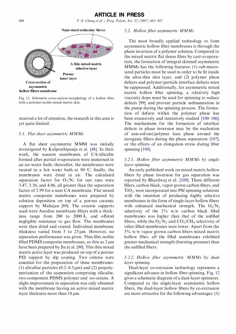
desirable structure of a hollow fiber with a mixed
matrix skin is shown in Fig. 11. The highly selective
particles are dispersed in the outer skin region of the
membranes. While methods to form asymmetric
membranes or multilayer composite membranes
with an ultrathin mixed matrix selective layer have
ARTICLE IN PRESS
OH
OH
Si
H3C
RO
RO
(CH2)3SiO
H3C
O
Modified zeolite (zeolite-NH2)
room temperature
N2, 24 h
zeolite
3A, 4A and 5A
(CH2)3NH2
NH2
silane
APDEMS (R = CH3CH2)
+
Filtering Drying
Washing with
toluene and methanol
In toluene
At 110 C for 1
hunder vacuum
Fig. 9. Flowchart of the chemical modification of zeolite surface [67].
0
0.2
0.4
0.6
PES-3A MMM PES-4A MMM PES-5A MMM5.8
6.4
7
PES-3A MMM PES-4A MMM PES-5A MMM
O2 Permeability (Barrer) O2 /N2 selectivity
Unmodified zeolite
Modified zeolite
Fig. 10. Comparison of gas permeability and gas pair selectivity of PES–zeolite A MMMs before and after the chemical modification of
zeolite surface [67].
T.-S. Chung et al. / Prog. Polym. Sci. 32 (2007) 483–507 497
8/13/2019 28 Mixed Matrix Membranes (MMMs) Comprising Organic Polymers With Dispersed Inorganic Fillers for Gas Separa…
http://slidepdf.com/reader/full/28-mixed-matrix-membranes-mmms-comprising-organic-polymers-with-dispersed 16/25
received a lot of attention, the research in this area isyet quite limited.
5.1. Flat sheet asymmetric MMMs
A flat sheet asymmetric MMM was initially
investigated by Kulprathipanja et al. [48]. In their
work, the nascent membranes of CA/silicalite
formed after partial evaporation were immersed in
an ice-water bath; thereafter, the membranes were
treated in a hot water bath at 90 1C; finally, the
membranes were dried in air. The calculatedseparation factor for O2/N2 for test runs were
3.47, 3.36, and 4.06, all greater than the separation
factor of 2.99 for a neat CA membrane. Flat mixed
matrix composite membranes were prepared by
solution deposition on top of a porous ceramic
support by Mahajan [89]. The ceramic supports
used were Anodisc membrane filters with a thick-
ness range from 200 to 2000 A ˚ , and offered
negligible resistance to gas flow. The membranes
were then dried and coated. Individual membrane
thickness varied from 5 to 25mm. However, no
separation performance was given. Thin-film zeolite
filled PDMS composite membranes, as thin as 3 mm
have been prepared by Jia et al. [90]. This thin mixed
matrix active layer was produced on top of a porous
PEI support by dip coating. Two criteria were
essential for the preparation of these membranes:
(1) ultrafine particles (0.2–0.5 mm) and (2) prepoly-
merization of the suspension comprising silicalite,
two-component PDMS polymer and iso-octane. A
slight improvement in separation was only obtained
with the membrane having an active mixed matrix
layer thickness more than 18 mm.
5.2. Hollow fiber asymmetric MMMs
The most broadly applied technology to form
asymmetric hollow fiber membranes is through the
phase inversion of a polymer solution. Compared to
the mixed matrix flat dense films by cast-evapora-tion, the formation of integral skinned asymmetric
MMMs has the following features: (1) sub-micro-
sized particles must be used in order to be fit inside
the ultra-thin skin layer, and (2) polymer phase
defects and polymer/particle interface defects must
be suppressed. Additionally, for asymmetric mixed
matrix hollow fiber spinning, a relatively high
viscosity dope must be used for spinning to reduce
defects [99] and prevent particle sedimentation in
the pump during the spinning process. The forma-
tion of defects within the polymer phase has
been extensively and intensively studied [100–106].The mechanisms for the formation of interface
defects in phase inversion may be the nucleation
of non-solvent/polymer lean phase around the
inorganic fillers during the phase separation [107],
or the effects of an elongation stress during fiber
spinning [108].
5.2.1. Hollow fiber asymmetric MMMs by single-
layer spinning
An early published work on mixed matrix hollow
fibers by phase inversion for gas separation wasreported by Bhardwaj et al. [109]. Three different
fillers, carbon black, vapor grown carbon fibers, and
TiO2, were incorporated into PSf spinning solutions
with the intention of producing highly selective
membranes in the form of single-layer hollow fibers
with enhanced mechanical strength. The O2/N2
selectivity of the 2% w/w carbon black filled
membranes was higher than that of the unfilled
fibers, while the O2/N2 and CO2/CH4 selectivity of
other filled membranes were lower. Apart from the
5% w/w vapor grown carbon fibers mixed matrix
hollow fiber, all the filled membranes exhibited
greater mechanical strength (bursting pressure) than
the unfilled fibers.
5.2.2. Hollow fiber asymmetric MMMs by dual-
layer spinning
Dual-layer co-extrusion technology represents a
significant advance in hollow fiber spinning. Fig. 12
gives a schematic diagram of a dual-layer spinneret.
Compared to the single-layer asymmetric hollow
fibers, the dual-layer hollow fibers by co-extrusion
are more attractive for the following advantages: (1)
ARTICLE IN PRESS
Fig. 11. Schematic cross-section morphology of a hollow fiber
with a polymer/zeolite mixed matrix skin.
T.-S. Chung et al. / Prog. Polym. Sci. 32 (2007) 483–507 498

8/13/2019 28 Mixed Matrix Membranes (MMMs) Comprising Organic Polymers With Dispersed Inorganic Fillers for Gas Separa…
http://slidepdf.com/reader/full/28-mixed-matrix-membranes-mmms-comprising-organic-polymers-with-dispersed 17/25
the dual-layer fibers can reduce material costs by
about 95% or even more, depending on the ratioof the inner layer to outer layer thickness; (2) by
means of choosing different materials for the two
layer and co-extrusion, it is possible to employ
brittle (engineering infeasible), but high perfor-
mance material as the outer layer to form the
composite membrane; (3) by choosing appropriate
inner layer and adjusting the dope solution con-
centration, the porosity in the resultant membrane
can be controlled and the dual-layer hollow fibers
can withstand high pressures; (4) the simultaneous
co-extrusion makes the formation of compositemembranes more straightforward and cost-effective
compared to other preparation approaches; and (5)
higher fluxes can be obtained in the single-step
production, since pore penetration, a common
problem in the subsequent dip-coating process is
avoided [111,112]. The findings in the research on
hollow fiber MMMs further add to the attraction of
this technology.
The MMM hollow fibers made by Miller et al.
[110] from the combination of polyaramide, PI or
cellulose with silicalite or ZSM-5 for the separation
of p-xylene from p-xylene/m-xylene mixtures. The
resultant mixed matrix hollow fibers possessed
selectivity for p/m-xylenes as high as 4, in contrast
with about 1 obtained with most polymeric mem-
branes. Hollow fibers having Ultems/CHA type
molecular sieves (pore size 3.8 A ˚ ) mixed matrix skins
were produced by Ekiner and Kulkarni [113]
employing this technology. The resultant hollow
fibers had O2 permeance between 7.4 and 9.5 GPU,
and O2/N2 selectivity ranging from 8.1 to 8.5. In
both patents [110,113], the outer layers containing
the selective skin had polymer/particle mixed matrix
structures, and the inner layers had neat polymeric
structures. As claimed, the application of the dual-
layer technology was mainly controlled by the
materials cost on the particles. In addition, silane
modification of zeolite surface followed by silane
linkage to the polymer chains at high temperatureswas adopted to improve compatibility between the
particle and the polymer. These pioneering studies
on hollow fibers with a dense mixed matrix skin
were released in patents [110,113,114] without
giving much scientific and engineering detail.
Another approach to combat polymer/particle
interface defects problem might be the modification
of the dispersed particles to increase surface
hydrophobicity, leading to a hypothesized suppres-
sion of the nucleation of the hydrophilic polymer
lean phase around the particles [107].
Unlike the aforementioned studies, a series of studies later contributed by Jiang et al. [115,117]
and Li et al. [116] proposed a new approach to
produce a defect-free mixed-matrix skin in hollow
fibers. In their work, it was found that a skin layer
without serious polymer/particle interface voids
could hardly be obtained in the traditional phase
inversion process [117]. Therefore, the dual-layer
co-extrusion technology was applied to control
particle distribution and create a situation for
subsequently removing defects in the mixed-matrix
skin. The materials for the outer layer are the mixedmatrix comprising a low T g glassy polymer (PSf or
PES) and nano-size beta zeolite. The polymers for
the inner layer are high T g glassy polymers
(Matrimids and P84s). The vast difference in T gbetween the outer and inner layers allows the
possibility of performing post-treatment (e.g., heat
treatment) to reduce or eliminate the defects in the
selective outer layer as well as to eliminate
delamination that may exist between the inner and
outer layers. When annealing at a temperature
above the T g
of the outer layer, the outer layer
becomes dense, with much fewer defects due to the
release of stress and relaxation of polymer chains in
the hollow fibers. A comparison of morphology
before and after heat treatment is shown in Fig. 13
[116]. In addition to heat treatment, a new method
of p-xylenediamine/methanol soaking was employed
to obtain an intimate polymer/zeolite interface
[117]. In prior studies to remove the interface
defects, the zeolite priming process was either
carried out before membrane fabrication (e.g.,
silane modification) or by co-mixing the primer
within the casting solutions; while in Jiang et al.’s
ARTICLE IN PRESS
Fig. 12. Schematic of dual-layer hollow fiber spinneret.
T.-S. Chung et al. / Prog. Polym. Sci. 32 (2007) 483–507 499

8/13/2019 28 Mixed Matrix Membranes (MMMs) Comprising Organic Polymers With Dispersed Inorganic Fillers for Gas Separa…
http://slidepdf.com/reader/full/28-mixed-matrix-membranes-mmms-comprising-organic-polymers-with-dispersed 18/25
[117] study, the priming process was performed after
hollow fibers formation and solvent exchange. The
new procedure may have the advantage of avoiding
the agglomeration of nanosize particles caused by
the entanglement of the surface modification
chemicals, as well as inducing rough zeolite surface,
thus reducing chain rigidification. Highly selective
mixed matrix hollow fibers for gas separations
resulted in these studies. Representative permeance
and selectivity in O2/N2 and CO2/CH4 separation
tests are shown in Fig. 14. The ideal selectivities of
the mixed matrix hollow fibers with a PSF/beta
outer layer (30 wt% of zeolite) and Matrimids
inner layer for O2/N2 and CO2/CH4 separation were
around 30% and 50% superior to that of the neat
PSF/Matrimids hollow fibers, respectively.
5.2.3. Particle distribution control in hollow fibers
In a flat sheet MMM, a high particle loading is
usually desirable to achieve better separation
properties. However, in hollow fiber spinning, an
increase in particle loadings may lead to extremely
high viscosity, inappropriate for practical fiber
spinning. Recent publications by Jiang et al. [108]
using nano-size beta zeolite, and Xiao et al. [118]
using nano-size TiO2 suggest the possibility of
controlling the particle distribution across the mixed
matrix hollow fiber membrane. Based on their
observations, the molecular sieve distribution den-
sity (or loading) in the polymer matrix of the outer
selective skin can be adjusted by the air gap or draw
ratio. Their approach provide a much more
convenient way of manipulating molecular sieve
ARTICLE IN PRESS
Fig. 13. Comparison of SEM morphologies of dual-layer PES/P84 hollow fiber membranes with a mixed matrix outer layer before and
after the heat-treatment (A–C) as-spun hollow fibers; (D–F) hollow fibers heat-treated at 235 1C) [116].
O2 Permeance (GPU)
O2 /N 2 selectivity
CO2 Permeance (GPU)
CO2 /CH 4 selectivity
0
0.5
1
0 10 20 300
5
10
0
2.5
5
0 10 20 300
25
50
Fig. 14. O2 permeance and O2/N2 selectivity of the dual-layer mixed matrix hollow fibers as a function of zeolite loading after coating:
with p-xylenediamine/ methanol soaking, heat treated at 200 1C for 2 h. Testing condition: 5 atm, 35 1C.
T.-S. Chung et al. / Prog. Polym. Sci. 32 (2007) 483–507 500

8/13/2019 28 Mixed Matrix Membranes (MMMs) Comprising Organic Polymers With Dispersed Inorganic Fillers for Gas Separa…
http://slidepdf.com/reader/full/28-mixed-matrix-membranes-mmms-comprising-organic-polymers-with-dispersed 19/25
distribution and magnifying the effect of molecular
sieves in gas separation asymmetric membranes
than by simply increasing the molecular sieve
loading in the dope solution, since the latter will
significantly increase the viscosity of the polymer
solution, and cause other problems on spinneretdesign and spinning process.
6. Modified Maxwell model for performance
prediction of MMMs
As has already been noted in Section 3.1, the
performance of MMMs can be predicted using the
Maxwell model. The Maxwell model was developed
in 1873 to predict the permittivity of a dielectric.
The constitutive equations governing electrical
potential and the flux through membranes areanalogs, permitting the application of Maxwell’s
results to transport in MMMs. The solution to
calculate the effective permeability of a MMM with
a dilute suspension of spherical particles can be
expressed by the well-known Maxwell equation
given by Eq. (4), representing an ideal case (no
defects and no distortion of the separation proper-
ties of the individual phase). This expression must
be modified to account for the non-ideal perfor-
mance of MMMs induced by interface voids,
polymer chain rigidification and pore blockage
(Section 5, Fig. 8).
Theoretical work on the influence of interface
voids (Case 2) in an MMM was first proposed by
Mahajan et al. [91] Due to the existence of the
interface voids (Fig. 8 Case 2), a three-phase system
includes the molecular sieve phase, the polymer
phase and the interface voids between these. The
permeability P 3MM of this three-phase membrane
was obtained by applying the Maxwell Model twice.
First, they suggested that gas flow through the
interface voids follows Knudsen diffusion, with a
slight modification to account for the finite size of the gas molecules:
DAK ¼ 9:7 105r
ffiffiffiffiffiffiffiffiT
M A
r 1
d g
2r
(5)
where DAK is the diffusion coefficient, r the effective
pore (defects) radius in A ˚ , T the absolute tempera-
ture, M A the gas molecular weight and d g is the
diameter of the gas molecule in A ˚ . The solution
coefficient, S , in these voids is assumed to be the
same as in the gas phase and has a partition
coefficient taking into considerations the size of the
gas molecules relative to the pore radius:
S ¼ 1
RT 1
d g
2r
2
(6)
The gas permeability P I through this interface is
the product of DAK and S .Second, a revised version of the Maxwell equa-
tion was used to obtain the permeability of the
combined interface void and molecular sieve phase
with the interface void as the continuous phase and
the molecular sieve phase as the disperse phase:
P eff ¼ P I
P d þ 2P I 2fsðP I P d Þ
P d þ 2P I þ fsðP I P d Þ
(7)
Here, P eff is the permeability of the combined
sieve and interface void, P d the permeability of the
dispersed or sieve phase, P I the permeability of the
interface void, fd the volume fraction of the sievephase, fi the volume fraction of the interface void,
and fs the volume fraction of the sieve phase in the
combined phase, given by
fs ¼ fd
fd þ fi
. (8)
Finally, the value of the permeability of the
combined sieve and interface void, P eff , can then be
used along with the continuous polymer phase
permeability, P c, to obtain a predicted permeability
P 3MM for the three-phase mixed matrix materials byapplying the Maxwell equation a second time:
P 3MM ¼ P cP eff þ 2P c 2ðfd þ fi ÞðP c P eff Þ
Pe ff þ 2P c þ ðfd þ fi ÞðP c P eff Þ
.
(9)
Thus, if one can make an estimate of the volume
fraction and the permeability of the interface void
region, the Maxwell model can easily be applied to
these more complicated morphologies. Where the
interface void diameter is large, which is common in
MMMs with stiff glassy polymers as the continuous
phase, the predicted selectivity by the Maxwell
model taking the Knudsen diffusion along the
interface void into consideration has never exceeded
the selectivity of the neat polymer phase, even
though the particles have extremely high selectivity.
This predicted phenomenon has been confirmed by
the experimental observations [89,90].
The approach in predicting the mixed matrix
performance in Case 2 can be readily extended to
Case 3 and Case 4, where polymer chain immobi-
lization and permeability reduction in the interface
region are used in place of Knudsen diffusion in the
ARTICLE IN PRESS
T.-S. Chung et al. / Prog. Polym. Sci. 32 (2007) 483–507 501

8/13/2019 28 Mixed Matrix Membranes (MMMs) Comprising Organic Polymers With Dispersed Inorganic Fillers for Gas Separa…
http://slidepdf.com/reader/full/28-mixed-matrix-membranes-mmms-comprising-organic-polymers-with-dispersed 20/25
interface voids. The parameters and equations for
Case 2–4 are detailed in Table 4 [53,119]. The work
on these modified Maxwell models has been
summarized in work by Moore and Koros [119],
with Ultems PEI/4A zeolite MMMs as the model
system. The predicted and experimental O2/N2selectivity vs. O2 permeability agreed well each
other, which confirms the above mentioned hypoth-
eses. In Mahajan’s [89] work, it was found that
polymer chain rigidification was dominant over
zeolite pore blockage. Recently, the Maxwell model
has been further modified by simultaneously con-
sidering both zeolite pore blockage and polymer
chain rigidification [66,67] as shown in Fig. 15. The
Maxwell equation was applied three times in this
modified Maxwell model to obtain the final predic-
tion of permeability of MMMs. This modified
Maxwell model fitted quite well with the experi-mental observation, as shown in Fig. 16. A Better fit
can be obtained by optimizing each polymer/
particle composite system with separate values of
the parameters l i and b.
By applying these modified equations, along with
the known intrinsic separation properties of bulk
polymer and porous filler, factors leading to non-
ideal performance in MMM, such as polymer chain
rigidification and pore blockage of inorganic
materials, can be estimated quantitatively and in
turn, used to help systematically search for methodsto offset the negative effects. However, so far only
the intrinsic permeability and selectivity of 4A
zeolite and CMS for use in O2/N2 and CO2/CH4
separations were obtained, but these were found to
be and relatively consistent with the model
[39–43,57]. For other inorganic materials, reliable
data cannot be found in the literature because too
many experimental conditions may influence the
separation properties of inorganic membranes, such
as the number of defects on the surface, the type of
supporting layer, inorganic membrane thickness,
etc. Therefore, quantitative work to match the
experimental and predicted results could only be
applied to these two materials of 4A zeolite and
CMS.
7. Conclusions and perspective
Investigations on MMMs have steadily increased
since 1980s when the MMM concept was demon-
strated by UOP LLC. Significant experimental
results confirm that MMMs show superior separa-
tion performance to neat polymeric membranes in
ARTICLE IN PRESS
T a
b l e 4
C o
m p a r i s o n o f t h e m o d i fi e d M a x w e l l M o d e l f o r c a s e s 2 , 3 , a n d 4 ( r e p r i n t e d f r o m
R e f . [ 1 1 9 ] , w i t h p e r m i s s i o n f r o m E l s e v
i e r ) .
C a
s e 2
C a s e 3
C a s e 4
P a r a m e t e r s
P I , v o i d p e r m e a b i l i t y
b , c h a i n i m m o b i l i z a t i o n f a c t o r
b 0 , p e r m e a b
i l i t y r e d u c t i o n
f a c t o r
P I ¼
D S
P I ¼
P C / b
P I ¼
P C / b 0
D a
¼
D K n u d s e n 1
s p 2 l 1
S a
¼
1 R T
1
s p 2 l 1
l j ,
v o i d t h i c k n e s s
l I , t h i c k n e s s o f r i g i d i fi e d r e g i o n
l j , t h i c k n e s s o f t h e r e d u c e d
p e r m e a b i l i t y r e g i o n
M o d e l f o r t h e p s e u d o - d i s p e r s e d
p h a s e p e r m e a b i l i t y
P e f f ¼
P I
P d þ
2 P I
2 f s ð P I
P d Þ
P d þ
2 P I þ
f s ð P I
P d Þ
f s ¼
f d
f d þ
f i
¼
r 3 d
ð r d þ
l i Þ 3 o r
ð r d þ
l i Þ 3
r 3 d
l i ¼
l I ;
l j o r l j 0
P s e u d o - d i s p e r s e d p h a s e
c o m p o n e n t s
Z e o l i t e + s u r r o u n d i n g v o i d s
Z e o l i t e + s u r r o u n d i n g p o l y m e r o f
r e d u c e d p e r m e a b i l i t y
Z e o l i t e ( i n c l u d i n g b u l k z e o l i t e
a n d r e g i o n o f r e d u c e d
p e r m e a b i l i t y )
M o d e l f o r t h e o v e r a l l m i x e d m a t r i x
m a
t e r i a l
P 3 M M
¼
P c
P e f f þ
2 P c
2 ð f d þ
f i Þ ð P c
P e f f Þ
P e f f þ
2 P c
þ
ð f d þ f
i Þ ð P c
P e f f Þ
T.-S. Chung et al. / Prog. Polym. Sci. 32 (2007) 483–507 502

8/13/2019 28 Mixed Matrix Membranes (MMMs) Comprising Organic Polymers With Dispersed Inorganic Fillers for Gas Separa…
http://slidepdf.com/reader/full/28-mixed-matrix-membranes-mmms-comprising-organic-polymers-with-dispersed 21/25
some gas mixtures separation. Clearly, MMMs are
promising next-generation membranes for gas
separation. However, as may be realized from the
preceding review, developments on the fabrication
and application of MMMs containing inorganic
particles inside polymer matrices for gas separation
are still quite low compared those for neatpolymeric membranes, providing an opportunity
for future developments. For example, it should be
noted that successful performance enhancement by
mixed matrix concept has been limited to a narrow
range of gas separations, summarized in Table 4. In
addition, there are few studies on industrially
applicable membrane morphology (e.g., asymmetric
membranes, thin-film composite membranes). This
is mainly due to the lack of sufficient information in
the separation properties of membrane materials
and fabrication properties of the mixed matrix
system.
The keys to the next-generation MMMs may be
to produce nano-size fillers less than 20 nm in size,
without agglomeration and to obtain their separa-
tion properties, especially the porous fillers. A
reliable and industrially qualified MMM for a
particular separation requires in-depth understand-
ing of separation mechanisms in this hybrid
membrane material. The intrinsic properties of the
polymer matrix in separation have been well
understood using the established technologies.
However, the rate of progress in understanding of
ARTICLE IN PRESS
Rigidified polymer region
Prig=PC / β
Zeolite skin affected by
the partial pore blockage
Pblo=PD / β'
The third phase [the second phase
(dispersed phase) + the rigidified
polymer region (continuous phase)]
The second phase [the bulk of zeolite(dispersed phase) + the zeolite skin with
partial pore blockage (continuous phase)]
Polymer chains
Zeolite 4A
Bulk of zeolite PD
Polymer matrix PC
3.8 A
r
r’
The first phase
(polymer matrix)
Fig. 15. Schematic diagram for the modified Maxwell model simultaneously considering both zeolite pore blockage and polymer chain
rigidification [67].
0
0.2
0.4
0.6
0.8
1
0 10 20 30 40 50 60
Zeolite loading (%)
Maxwell model prediction
Modified Maxwell model prediction
Experimental results
O2 Permeability
5
7
9
11
13
0 10 20 30 40 50 60
Zeolite loading (%)
O2 /N2selectivity
Maxwell model prediction
Modified Maxwellmodel prediction
Experimental results
a
b
Fig. 16. (A) Comparison of O2 permeability PES-4A-NH2
MMMs between experimental data and predictions from the
Maxwell model and the modified Maxwell model [67]. (B)
Comparison of O2/N2 selectivity of PES-4A-NH2 MMMs
between experimental data and predictions from the Maxwell
model and the modified Maxwell model [67].
T.-S. Chung et al. / Prog. Polym. Sci. 32 (2007) 483–507 503

8/13/2019 28 Mixed Matrix Membranes (MMMs) Comprising Organic Polymers With Dispersed Inorganic Fillers for Gas Separa…
http://slidepdf.com/reader/full/28-mixed-matrix-membranes-mmms-comprising-organic-polymers-with-dispersed 22/25
inorganic materials falls well behind that of polymer
membranes. This makes the material selection a big
problem. Therefore, a reliable and standard ap-
proach is badly needed to identify the separation
properties of inorganic materials.
The complicated situations existing at the inter-face connecting the polymer and particles make the
formation of MMMs with expected performance
difficult. The interface defects may make the
inorganic particles be isolated from the transport
process. The chain immobilization and pore block-
age around the interface region could probably
lower the permeability. The mechanisms behind
these phenomena require intensive investigation.
Recent molecular dynamic simulations of mixed
matrix materials have shown decreased polymer
chain mobility and permeability near an interface
[53]. Additionally, molecular dynamic simulation of small penetrants in bulk and confined polymer
membranes was performed to understand the effects
of confinement on the permeability and selectivity
[120]. Changes in the microstructure and dynamics
of the polymer were observed upon confinement.
With the advances in these works, the effects of
particle size and geometry, pore size and geometry,
and the polymer/particle interface should also be
examined.
Hollow fibers are one of the most efficient
membrane morphologies. Nevertheless, researchon fabrication of mixed matrix hollow fibers is
quite limited. Regarding the different formation
mechanisms of dense films from asymmetric mem-
branes, the following aspects should be considered
for the formation of defect-free mixed matrix
structure in asymmetric membranes: (1) the effect
of the rheological properties of the dope solutions
and the spinning conditions on skin layer forma-
tion, (2) the effect of particle shape and hydro-
philicity on the skin layer micro-scale morphology
during phase inversion, and (3) a reduction in the
skin layer thickness, which entails the employment
of ultrafine particles.
As can be concluded in this review, the major gas
separations by MMM include air separation and
natural gas separation. The investigations on high
value-added separations are limited. In the reported
studies, the researches on i -pentane/n-pentane se-
paration, H2/CO2 separation, n-butane/methane
separation paved the way for future work. However,
compared to the broad range of separations carried
out by neat polymeric membranes, these cases
studies are still quite minimal. This indicates that
MMM still have a long way to go to fully exploit its
potentials.
Acknowledgements
The authors would like to thank A-star, UOPLLC, and NUS for funding this research with the
grant numbers of R-398-000-029-305, R-279-000-
010-001, and R-279-000-184-112.
References
[1] Rousseau RW. Handbook of separation process technol-
ogy. New York: Wiley; 1987.
[2] Nunes SPN, Peinemann KV. Membrane technology in the
chemical industry. Weinheim, Singapore: Wiley-VCH;
2001.[3] Berry RI. Membrane separate gas. Chem Eng 1981;88:
63–7.
[4] Strathman H. Membrane separation process. J Membr Sci
1981;9:121–89.
[5] Spillman RW, Sherwin MB. Gas separation membranes:
the first decade. Chem Technol 1990;20:378–408.
[6] Paul DR, Yampol’skii YP. Polymeric gas separation
membranes. Boca Raton, FL: CRC Press; 1994.
[7] Stern SA. Polymers for gas separations: the next decade.
J Membr Sci 1994;94:1–65.
[8] Mulder M. Basic principles of membrane technology.
Dordrecht: Kluwer Academic Publisher; 1996.
[9] Ho WSW, Sirkar KK. Membrane handbook. New York:
Van Nostrand Reinhold; 1992.
[10] Kesting RE, Fritzsche AK. Polymeric gas separation
membranes. New York: Wiley; 1993.
[11] Spillman RW. Economics of gas separation membranes.
Chem Eng Prog 1989;85:41–62.
[12] Meindersma GW, Kuczynskyi M. Implementing mem-
brane technology in the process industry: problems and
opportunities. J Membr Sci 1996;113:285–92.
[13] Freeman BD, Pinnau I. Polymer membrane for gas and
vapor separations: chemistry and material science. Wa-
shington, DC: American Chemical Society; 1999.
[14] Freeman BD, Pinnau I. Separation of gases using
solubility-selective polymer. Trends Polym Sci 1997;5:
167–73.[15] Pinnau I, Freeman BD. Membrane formation and mod-
ification: overview. Washington, DC: American Chemical
Society; 1990.
[16] Koros WJ, Flemming GK. Membrane-based gas separa-
tion. J Membr Sci 1993;83:1–80.
[17] Bos A, Punt IG, Wessling M, Strathmann H. Plasticiza-
tion-resistant glassy polyimide membrane for CO2/CH4
separations. Sep Purif Technol 1998;14:27–39.
[18] McCaig MS, Paul DR. Effect of UV cross-linking and
physical aging on the gas permeability of the thin glassy
polyacrylate films. Polymer 1999;40:7209–25.
[19] Bos A, Punt I, Strathmann H, Wessling M. Suppression of
gas separation membrane plasticization by homogeneous
polymer blending. AIChE J 2001;47:1088–93.
ARTICLE IN PRESS
T.-S. Chung et al. / Prog. Polym. Sci. 32 (2007) 483–507 504

8/13/2019 28 Mixed Matrix Membranes (MMMs) Comprising Organic Polymers With Dispersed Inorganic Fillers for Gas Separa…
http://slidepdf.com/reader/full/28-mixed-matrix-membranes-mmms-comprising-organic-polymers-with-dispersed 23/25
[20] Tin PS, Chung TS, Liu Y, Wang R, Liu SL, Pramoda KP.
Effect of cross-linking on gas separation performance of
Matrimid membranes. J Membr Sci 2003;225:77–90.
[21] Shao L, Chung TS, Hong GH, Pramoda KP. Polyimide
modification by a linear aliphatic diamine to enhanced
transport performance and plasticization resistance.
J Membr Sci 2005;256:46–56.[22] Chung TS, Shao L, Tin PS. Surface modification of
polyimide membranes by diamines for H2 and CO2
separation. Macromol Rapid Commun 2006;27:998–1003.
[23] Morisato A, He Z, Pinnau I, Merkel TC. Transport
properties of PA 12-PTMO/AgBF4 solid polymer electro-
lyte membranes for olefin/paraffin separation. Desalination
2002;145:347–51.
[24] Morooka S, Kusakabe K. Microporous inorganic mem-
branes for gas separation. MRS Bull 1999;24:25–9.
[25] Koresh JE, Soffer A. Study of molecular sieve carbons.
Part 2. Estimation of cross-sectional diameters of non-
spherical molecules. J Chem Soc Faraday I 1980;76:
2472–80.
[26] Rao MB, Sircar S. Performance and pore characterizationof nanoporous carbon membranes for gas separation.
J Membr Sci 1996;110:109–18.
[27] Pandy P, Chauhan RS. Membranes for gas separation.
Prog Polym Sci 2001;26:853–93.
[28] Kusakabe K, Kuroda T, Morooka S. Separation of carbon
dioxide from nitrogen using ion-exchanged faujasite-type
zeolite membranes formed on porous support tubes.
J Membr Sci 1998;148:13–23.
[29] Kita H, Fuchida K, Horita T, Asamura H, Okamoto K.
Preparation of faujasite membranes and their permeation
properties. Sep Purif Technol 2001;25:261–8.
[30] Tuan VA, Li S, Falconer JL, Noble RD. In situ crystal-
lization of beta zeolite membranes and their permeation
and separation properties. Chem Mater 2002;14:489–92.
[31] Yan Y, Davis ME, Gavalas GR. Preparation of zeolite
ZSM-5 membranes by in situ crystallization on porous
Al2O3. Ind Eng Chem Res 1995;34:1652–61.
[32] Nishiyama N, Ueyama K, Matsukata M. Synthesis of FER
membrane on an alumina support and its separation
properties. Stud Surf Sci Catal 1997;105:2195–205.
[33] Aoki K, Kusakabe K, Morooka S. Gas permeation
properties of A-type zeolite membranes formed on porous
substrate by hydrothermal synthesis. J Membr Sci 1998;
141:197–209.
[34] Li S, Falconer JL, Noble RD. SAPO-34 membranes for
CO2/CH4 separation. J Membr Sci 2004;241:121–35.
[35] Vu DQ, Koros WJ, Miller SJ. High pressure CO2/CH4
separation using carbon molecular sieve hollow fiber
membranes. Ind Eng Chem Res 2002;41:367–80.
[36] Okamoto K, Kawamura S, Yoshino M, Kita H, Hirayama
Y, Tanihara N. Olefin/paraffin separation through carbo-
nized membranes derived from an asymmetric polyimide
hollow fiber membrane. Ind Eng Chem Res 1999;38:
4424–32.
[37] Xiao YC, Dai Y, Chung TS, Guiver MD. Effects of
brominating Matrimid polyimide on the physical and gas
transport properties of derived carbon membranes. Macro-
molecules 2005;38:10042–9.
[38] Robeson LM. Correlation of separation factor versus
permeability for polymeric membranes. J Membr Sci 1991;
62:165–85.
[39] Singh AS, Koros WJ. Air separation properties of flat sheet
homogeneous pyrolytic carbon membranes. J Membr Sci
2000;174:177–88.
[40] Feuters AB, Centeno TA. Preparation of supported carbon
molecular membranes. Carbon 1999;37:679–84.
[41] Kim YK, Lee JM, Park HB, Lee YM. The gas separation
properties of carbon molecular sieve membranes derivedfrom polyimides having carboxylic acid groups. J Membr
Sci 2004;235:139–46.
[42] Park HB, Kim YK, Lee JM, Lee SY, Lee YM. Relation-
ship between chemical structure of aromatic polyimides
and gas permeation properties of their carbon molecular
sieve membranes. J Membr Sci 2004;229:117–27.
[43] Tin PS, Chung TS, Kawi S, Guiver MD. Novel approaches
to fabricate carbon molecular sieve membranes based on
chemical modified and solvent treated polyimides. Micro-
por Mesopor Mater 2004;73:151–60.
[44] Saracco G, Neomagus HWJP, Versteeg GF, Van Swaaij
WPM. High-temperature membrane reactor: potential and
problems. Chem Eng Sci 1999;54:1997–2017.
[45] Caro J, Noack M, Kolsch P, Schaefer R. Zeolitemembrane-state of their development and perspective.
Micropor Mesopor Mater 2000;38:3–24.
[46] Paul DR, Kemp DR. The diffusion time lag in polymer
membranes containing adsorptive fillers. J Polym Sci:
Polym Phys 1973;41:79–93.
[47] Kulprathipanja S, Neuzil RW, Li NN. Separation of fluids
by means of mixed matrix membranes. US patent 4740219,
1988.
[48] Kulprathipanja S, Neuzil RW, Li NN. Separation of gases
by means of mixed matrix membranes. US patent 5127925,
1992.
[49] Bouma RHB, Checchetti A, Chidichimo G, Drioli E.
Permeation through a heterogeneous membrane: the effect
of the dispersed phase. J Membr Sci 1997;128:141–9.
[50] Maxwell JC. Treatise on electricity and magnetism.
London: Oxford University Press; 1873.
[51] Anand M, Langsam M, Rao MB, Sircar S. Multicompo-
nent gas separation by selective surface flow (SSF) and
polytrimethysilylpropyne (PTMSP) membranes. J Membr
Sci 1997;123:17–25.
[52] Sircar S, Rao MB, Thaeron CMA. Selective surface flow
membranes for gas separation. Sep Sci Technol 1999;34:
2081–93.
[53] Moore TT, Mahajan R, Vu DQ, Koros WJ. Hybrid
membrane materials comprising organic polymers with
rigid dispersed phases. AIChE J 2004;50:311–21.
[54] Mahajan R, Koros WJ. Factors controlling successfulformation of mixed-matrix gas separation materials. Ind
Eng Chem Res 2000;39:2692–6.
[55] Mahajan R, Koros WJ. Mixed matrix membrane materials
with glassy polymers. Part 1. Polym Eng Sci 2002;42:
1420–31.
[56] Mahajan R, Koros WJ. Mixed matrix membrane materials
with glassy polymers. Part 2. Polym Eng Sci 2002;42:
1432–41.
[57] Ruthven DM, Derrah RI. Diffusion of monoatomic and
diatomic gases in 4A and 5A zeolites. J Chem Soc: Faraday
Trans 1975;71:2031–7.
[58] Merkel TC, Freeman BD, Spontak RJ, He Z, Pinnau I.
Ultrapermeable, reverse-selective nanocomposite mem-
branes. Science 2002;296:519–22.
ARTICLE IN PRESS
T.-S. Chung et al. / Prog. Polym. Sci. 32 (2007) 483–507 505

8/13/2019 28 Mixed Matrix Membranes (MMMs) Comprising Organic Polymers With Dispersed Inorganic Fillers for Gas Separa…
http://slidepdf.com/reader/full/28-mixed-matrix-membranes-mmms-comprising-organic-polymers-with-dispersed 24/25
[59] He Z, Pinnau I, Morisato A. Nanostructured poly
(4-methyl-2-pentyne)/silica hybrid membranes for gas
separation. Desalination 2002;146:11–5.
[60] Merkel TC, He Z, Pinnau I, Freeman BD, Meakin P, Hill
AJ. Sorption and transport in poly (2,2-bis(trifluoro-
methyl)-4,5-difluoro-1,3-dioxole-co-tetrafluoro-ethylene)
containing nanoscale fumed silica. Macromolecules 2003;36:8406–14.
[61] Duval JM. Adsorbent filled polymeric membranes. PhD
thesis. The Netherlands: University of Twente; 1995.
[62] Boom JP. Transport through zeolite filled polymeric
membranes. Ph. D. Thesis, The Netherlands: University
of Twente; 1994.
[63] Suer MG, Bac N, Yilmaz L. Gas permeation characteristics
of polymer–zeolite mixed matrix membranes. J Membr Sci
1994;91:77–86.
[64] Yong HH, Park HC, Kang YS, Won J, Kim WN. Zeolite-
filled polyimide membrane containing 2,4,6-triaminopyr-
imidine. J Membr Sci 2001;188:151–63.
[65] Ersolmaz SBT, Senorkyan L, Kalaonra N, Tatlier M,
Senatalar AE. n-Pentane/i -pentane separation by usingzeolite–PDMS mixed matrix membranes. J Membr Sci
2001;189:59–67.
[66] Li Y, Chung TS, Cao C, Kulprathipanja S. The effects of
polymer chain rigidification, zeolite pore size and pore
blockage on polyethersulfone (PES)–zeolite A mixed
matrix membranes. J Membr Sci 2005;260:45–55.
[67] Li Y, Guan HM, Chung TS, Kulprathipanja S. Effects of
novel silane modification of zeolite surface on polymer
chain rigidification and partial pore blockage in polyether-
sulfone (PES)–zeolite A mixed matrix membranes.
J Membr Sci 2006;275:17–28.
[68] Clarizia G, Algieri C, Drioli E. Filler–polymer combina-
tion: a route to modify gas transport properties of a
polymeric membrane. Polymer 2004;45:5671–81.
[69] Jia M, Peinemann KV, Behling RD. Molecular sieving
effect of the zeolite-filled silicone rubber membranes in gas
permeation. J Membr Sci 1991;57:289–92.
[70] Kulkarni SS, David HJ, Corbin DR, Patel AN. Gas
separation membrane with organosilicon-treated molecular
sieve. US patent 6580860, 2003.
[71] Hasse DJ, Kulkarni SS, Corbin DR, Patel AN. Mixed
matrix membranes incorporating chabazite type molecular
sieves. US patent 6626980, 2003.
[72] Wang H, Holmberg BA, Yan Y. Homogeneous polymer–
zeolites nano composite membranes by incorporating
dispersible template-removed zeolite nanoparticles. J Mater
Chem 2002;12:3640–3.[73] Pechar TW, Kim S, Vaughan B, Marand E, Baranauskas
V, Riffle J, et al. Preparation and characterization of a poly
(imide siloxane) and zeolite L mixed matrix membrane.
J Membr Sci 2006;277:210–8.
[74] Pechar TW, Kim S, Vaughan B, Marand E, Tsapatsis M,
Jeong HK, et al. Fabrication and characterization of
polyimide–zeolite L mixed matrix membranes for gas
separation. J Membr Sci 2006;277:195–202.
[75] Guiver MD, Robertson GP, Dai Y, Bilodeau F, Kang YS,
Lee KJ, et al. Structural characterization and gas-transport
properties of brominated Matrimid polyimide. J Polym Sci:
Polym Chem 2003;40:4193–204.
[76] Rojey AR, Deschamps A, Grehier A, Robert E. Process
for separation of the constituents of a mixture in the gas
phase using a composite membrane. US patent 4925459,
1990.
[77] Vu DQ, Koros WJ, Miller SJ. Mixed matrix membranes
using carbon molecular sieves. I. Preparation and experi-
mental results. J Membr Sci 2003;211:311–34.
[78] Vu DQ, Koros WJ, Miller SJ. Mixed matrix membranes
using carbon molecular sieves. II. Modeling permeationbehavior. J Membr Sci 2003;211:335–48.
[79] Vu DQ, Koros WJ, Miller SJ. Effect of condensable
impurity in CO2/CH4 gas feeds on performance of mixed
matrix membranes using carbon molecular sieves. J Membr
Sci 2003;221:233–9.
[80] Duval JM, Folkers B, Mulder MHV, Desgrandchamps G,
Smolders CA. Adsorbent filled membranes for gas separa-
tion. Part 1. Improvement of the gas separation properties
of polymeric membranes by incorporation of microporous
adsorbents. J Membr Sci 1993;80:189–98.
[81] Anson M, Marchese J, Garis E, Ochoa N, Pagliero C. ABS
copolymer-activated carbon mixed matrix membrane for
CO2/CH4 separation. J Membr Sci 2004;243:19–28.
[82] Moaddeb M, Koros WJ. Gas transport properties of thinpolymeric membranes in the presence of silicon dioxide
particles. J Membr Sci 1997;125:143–63.
[83] Merkel TC, He Z, Pinnau I, Freeman BD, Meakin P, Hill
AJ. Effect of nanoparticles on gas sorption and transport in
poly (1-trimethylsilyl-1-propyne). Macromolecules 2003;36:
6844–55.
[84] Chung TS, Chan SS, Wang R, Lu Z, He C. Characteriza-
tion of permeability and sorption in Matrimid/C60 mixed
matrix membranes. J Membr Sci 2003;211:91–9.
[85] Meier WM, Olson DH. Altas of zeolite structure types, 3rd
ed. London: Butterworths; 1992.
[86] Li Y, Chung TS, Kulprathipanja S. Novel Ag+-zeolite/
polymer mixed matrix membranes with a high CO2/CH4
selectivity. AIChE J 2007;53:610–6.
[87] Zimmerman CM, Singh A, Koros WJ. Tailoring mixed
matrix composite membranes for gas separations. J Membr
Sci 1997;137:145–54.
[88] Tantekin-Ersolmaz SB. Effect of zeolite particle size on the
performance of polymer–zeolite mixed matrix membrane.
J Membr Sci 2000;175:285–8.
[89] Mahajan R. Formation, characterization and modeling of
mixed matrix membrane materials. PhD thesis. Univeristy
of Texas at Austin, 2000.
[90] Jia M, Peinemann KV, Behling RD. Preparation and
characterization of thin-film zeolite–PDMS composite
membranes. J Membr Sci 1992;73:119–28.
[91] Mahajan R, Burns R, Schaeffer M, Koros WJ. Challengesin forming successful mixed matrix membranes with rigid
polymeric materials. J Appl Poly Sci 2002;86:881–90.
[92] Levich VG, Krylov VS. Surface-tension-drive phenomena.
Annu Rev Fluid Mech 1969;1:293–316.
[93] Barrer RM, James SD. Electrochemistry of crystal-polymer
membranes. I. Resistance measurements. J Phys Chem
1960;64:417–21.
[94] Vankelecom IFJ, Mercks E, Luts M, Uytterhoeven JB.
Incorporation of zeolite in polyimide membranes. J Phys
Chem 1995;99:13187–92.
[95] Vankelecom IFJ, Broeck SVD, Mercks E, Geerts H,
Grobet P, Yutterhoeven JB. Silylation to improve incor-
poration of zeolites in polyimide films. J Phys Chem
1996;100:3753–8.
ARTICLE IN PRESS
T.-S. Chung et al. / Prog. Polym. Sci. 32 (2007) 483–507 506

8/13/2019 28 Mixed Matrix Membranes (MMMs) Comprising Organic Polymers With Dispersed Inorganic Fillers for Gas Separa…
http://slidepdf.com/reader/full/28-mixed-matrix-membranes-mmms-comprising-organic-polymers-with-dispersed 25/25
[96] Pechar TW, Tspatsis M, Marand E, Davis R. Preparation
and characterization of a glassy fluorinated polyimide
zeolite-mixed matrix membrane. Desalination 2002;146:
3–9.
[97] Shu S, Husain S, Koros WJ. Formation of nanoscale
morphology on zeolite surface for enhanced interfacial
interaction in mixed matrix membranes. Chicago, IL:North American Membrane Society; 2006.
[98] Loeb S, Sourirajan S. Sea water demineralization by
means of an osmotic membrane. Adv Chem Ser 1962;38:
117–32.
[99] Chung TS, Kafchinski ER, Vora RH. Development of a
defect-free 6FDA durene asymmetric hollow fibers and its
composite hollow fibers. J Membr Sci 1994;88:21–36.
[100] Pinnau I, Koros WJ. Structures and gas separation
properties of asymmetric polysulfone membranes made
by dry, wet, and dry/wet phase inversion. J Appl Polym Sci
1991;43:1491–502.
[101] Fritzsche AK, Cruse CA, Kesting RE, Murphy MK.
Polysulfone hollow-fiber membranes spun from Lewis
acid:base complexes. Part II. The effect of Lewis acid-to-base ratio on membrane structure. J Appl Polym Sci 1990;
39:1949–56.
[102] Kesting RE, Fritzsche AK, Cruse CA, Moore MD. The
second-generation polysulfone gas-separation membrane.
II. The relationship between sol properties, gel macrovoids,
and fiber selectivity. J Appl Polym Sci 1990;40:1575–82.
[103] Cabasso I, Klein E, Smith JK. Polysulfone hollow fibers. II.
Morphology. J Appl Polym Sci 1977;21:165–80.
[104] Ekiner OM, Vassilatos G. Polyaramide hollow fibers for
hydrogen/methane separation—spinning and properties.
J Membr Sci 1990;53:259–73.
[105] Pesek SC, Koros WJ. Aqueous quenched asymmetric
polysulfone membranes prepared by dry/wet phase separa-
tion. J Membr Sci 1993;81:71–88.
[106] Wang DL, Li K, Teo WK. Polyethersulfone hollow fiber
gas separation membranes prepared from NMP/alcohol
solvent systems. J Membr Sci 1996;115:85–108.
[107] Husain S, Koros WJ. In mixed matrix hollow fibers for gas
separation. Providence, RI: North American Membrane
Society; 2005.
[108] Jiang LY, Chung TS, Cao C, Huang Z, Kulprathipanja S.
Fundamental understanding of nano-sized zeolite distribu-
tion in the formation of the mixed matrix single- and dual-
layer asymmetric hollow fiber membranes. J Membr Sci
2005;252:89–100.
[109] Bhardwaj V, Macintosh A, Sharpe ID, Gordeyev SA,
Shilton SJ. Polysulfone hollow fiber gas separation
membranes filled with submicron particles. Ann NY Acad
Sci 2003;984:318–28.
[110] Miller SJ, Munson CL, Kulkarni SS, Hasse DJ. Purifica-tion of p-xylene using composite mixed matrix membranes.
US patent 6500233, 2002.
[111] Jiang LY. Fabrication and characterization of composite
membranes for gas separation. PhD thesis. Singapore:
National University of Singapore; 2006.
[112] Li Y. Development of mixed matrix membranes for gas
separation application. PhD Thesis. Singapore: National
University of Singapore; 2006.
[113] Ekiner OM, Kulkarni SS. Process for making hollow fiber
mixed matrix membranes. US patent 6663805, 2003.
[114] Koros WJ, Wallace D, Wind JD, Miller SJ, Bickel CS, Vu
DQ. Crosslinked and crosslinkable hollow fiber mixed
matrix membrane and method of making the same. US
patent 6755900, 2004.[115] Jiang LY, Chung TS, Kulprathipanja S. An investigation
to revitalize the separation performance of hollow fibers
with a thin mixed matrix composite skin for gas separation.
J Membr Sci 2006;276:113–25.
[116] Li Y, Chung TS, Huang Z. Dual-layer polyethersulfone
(PES)/BTDA-TDI/MDI co-polyimide (P84) hollow fiber
membranes with a submicron PES–zeolite beta mixed
matrix dense-selective layer for gas separation. J Membr
Sci 2006;277:28–37.
[117] Jiang LY, Chung TS, Kulprathipanja S. A novel approach
to fabricate mixed matrix hollow fibers with superior
intimate polymer/zeolite interface for gas separation.
AIChE J 2006;52:2898–908.
[118] Xiao YC, Wang KY, Chung TS, Tan J. Evolution of nano-
particle distribution during the fabrication of mixed matrix
TiO2-polyimide hollow fiber membranes. Chem Eng Sci
2006;61:6228–33.
[119] Moore TT, Koros WJ. Non-ideal effects in organic-
inorganic materials for gas separation membranes. J Mol
Struct 2005;739:87–98.
[120] Rallabandi PS, Ford DM. Permeation of small molecules
through polymers confined in mesoporous media. J Membr
Sci 2000;171:239–52.
ARTICLE IN PRESS
T.-S. Chung et al. / Prog. Polym. Sci. 32 (2007) 483–507 507