Embed Size (px)
Citation preview
Supplementing the Little League® 2017 Operating Manual Lighting Information
2017 Little League® Lighting Standards
& Safety Audit

TABLE OF CONTENTSIntroduction 1I. Required Minimum Standards
Part 1 - General1.1 Lighting Performance 21.2 Environmental Light Control 41.3 Life-Cycle Costs 41.4 Warranty and Guarantee 4
Part 2 - Product2.1 Lighting System Construction 42.2 Structural Parameters 6
Part 3 - Execution3.1 Field Quality Control 6 3.2 Ongoing Quality Assurance 6
II. Desirable Features4.1 Control & Monitoring System 74.2 Auxiliary Brackets 74.3 Field Perimeter Lighting 7
III. Life-Cycle Operating Cost Evaluation 8
IV. Little League Lighting Standards Checklist 9
V. Facility Drawings 10 – 11
VI. Safety Audit 12 – 15
©1992, 2017 Little League® Baseball and Softball
1
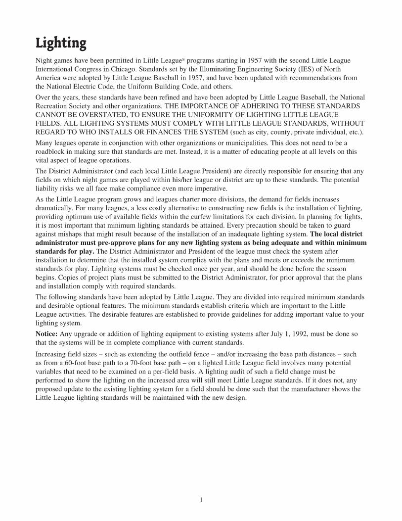
Night games have been permitted in Little League® programs starting in 1957 with the second Little League International Congress in Chicago. Standards set by the Illuminating Engineering Society (IES) of North America were adopted by Little League Baseball in 1957, and have been updated with recommendations from the National Electric Code, the Uniform Building Code, and others.
Over the years, these standards have been refined and have been adopted by Little League Baseball, the National Recreation Society and other organizations. THE IMPORTANCE OF ADHERING TO THESE STANDARDS CANNOT BE OVERSTATED, TO ENSURE THE UNIFORMITY OF LIGHTING LITTLE LEAGUE FIELDS. ALL LIGHTING SYSTEMS MUST COMPLY WITH LITTLE LEAGUE STANDARDS, WITHOUT REGARD TO WHO INSTALLS OR FINANCES THE SYSTEM (such as city, county, private individual, etc.).
Many leagues operate in conjunction with other organizations or municipalities. This does not need to be a roadblock in making sure that standards are met. Instead, it is a matter of educating people at all levels on this vital aspect of league operations.
The District Administrator (and each local Little League President) are directly responsible for ensuring that any fields on which night games are played within his/her league or district are up to these standards. The potential liability risks we all face make compliance even more imperative.
As the Little League program grows and leagues charter more divisions, the demand for fields increases dramatically. For many leagues, a less costly alternative to constructing new fields is the installation of lighting, providing optimum use of available fields within the curfew limitations for each division. In planning for lights, it is most important that minimum lighting standards be attained. Every precaution should be taken to guard against mishaps that might result because of the installation of an inadequate lighting system. The local district administrator must pre-approve plans for any new lighting system as being adequate and within minimum standards for play. The District Administrator and President of the league must check the system after installation to determine that the installed system complies with the plans and meets or exceeds the minimum standards for play. Lighting systems must be checked once per year, and should be done before the season begins. Copies of project plans must be submitted to the District Administrator, for prior approval that the plans and installation comply with required standards.
The following standards have been adopted by Little League. They are divided into required minimum standards and desirable optional features. The minimum standards establish criteria which are important to the Little League activities. The desirable features are established to provide guidelines for adding important value to your lighting system.
Notice: Any upgrade or addition of lighting equipment to existing systems after July 1, 1992, must be done so that the systems will be in complete compliance with current standards.
Increasing field sizes – such as extending the outfield fence – and/or increasing the base path distances – such as from a 60-foot base path to a 70-foot base path – on a lighted Little League field involves many potential variables that need to be examined on a per-field basis. A lighting audit of such a field change must be performed to show the lighting on the increased area will still meet Little League standards. If it does not, any proposed update to the existing lighting system for a field should be done such that the manufacturer shows the Little League lighting standards will be maintained with the new design.
Lighting
2
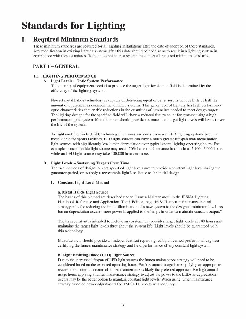
Standards for LightingI. Required Minimum Standards
These minimum standards are required for all lighting installations after the date of adoption of these standards. Any modification in existing lighting systems after this date should be done so as to result in a lighting system in compliance with these standards. To be in compliance, a system must meet all required minimum standards.
PART 1 – GENERAL
1.1 LIGHTING PERFORMANCE A. Light Levels – Optic System Performance
The quantity of equipment needed to produce the target light levels on a field is determined by the efficiency of the lighting system.
Newest metal halide technology is capable of delivering equal or better results with as little as half the amount of equipment as common metal halide systems. This generation of lighting has high performance optic characteristics that enable reductions in the quantities of luminaires needed to meet design targets. The lighting designs for the specified field will show a reduced fixture count for systems using a high-performance optic system. Manufacturers should provide assurance that target light levels will be met over the life of the system.
As light emitting diode (LED) technology improves and costs decrease, LED lighting systems become more viable for sports facilities. LED light sources can have a much greater lifespan than metal halide light sources with significantly less lumen depreciation over typical sports lighting operating hours. For example, a metal halide light source may reach 70% lumen maintenance in as little as 2,100 – 3,000 hours while an LED light source may take 100,000 hours or more.
B. Light Levels – Sustaining Targets Over Time The two methods of design to meet specified light levels are: to provide a constant light level during the
guarantee period, or to apply a recoverable light loss factor to the initial design.
1. Constant Light Level Method
a. Metal Halide Light Source The basics of this method are described under “Lumen Maintenance” in the IESNA Lighting
Handbook Reference and Application, Tenth Edition, page 16-8: “Lumen maintenance control strategy calls for reducing the initial illumination of a new system to the designed minimum level. As lumen depreciation occurs, more power is applied to the lamps in order to maintain constant output.”
The term constant is intended to include any system that provides target light levels at 100 hours and maintains the target light levels throughout the system life. Light levels should be guaranteed with this technology.
Manufacturers should provide an independent test report signed by a licensed professional engineer certifying the lumen maintenance strategy and field performance of any constant light system.
b. Light Emitting Diode (LED) Light Source Due to the increased lifespan of LED light sources the lumen maintenance strategy will need to be
considered based on the expected operating hours. For low annual usage hours applying an appropriate recoverable factor to account of lumen maintenance is likely the preferred approach. For high annual usage hours applying a lumen maintenance strategy to adjust the power to the LEDs as depreciation occurs may be the better option to maintain constant light levels. When using lumen maintenance strategy based on power adjustments the TM-21-11 reports will not apply.
3
2. Recoverable Light Loss Factor Method
a. Metal Halide Light Source Computer designs are done using two sets of values. One shows the calculated “initial light levels” when
lamps are new. The other predicts “target maintained light levels” after the lamps have passed through depreciation in light output. It is important to have the lighting designer use a maintenance factor adequate to account for this depreciation in light output throughout the life of the lamp.
According to best sports lighting practices, the recoverable light loss factor, or the value applied to the initial light level to predict the maintained light level values, should be in accordance with recommendations in the Pennsylvania State University report “Light Loss Factors for Sports Lighting,” published in IES’s Leukos, Vol. 6, No. 3, Jan., 2010, pages 183–201. The report’s findings show a recoverable light loss factor of 0.65 should be used if lamps will be replaced at 3000 hours. Quality manufacturers are willing to provide guarantees of lighting performance.
b. Light Emitting Diode (LED) Light Source The life of an LED is significantly longer than metal halide, and depreciation is more gradual early in
life. If the amount of lumen depreciation will impact the target light levels during the system life then an appropriate lumen maintenance factor should be applied. It is recommended to obtain the lumen maintenance report per TM-21-11, of the fixture being proposed.
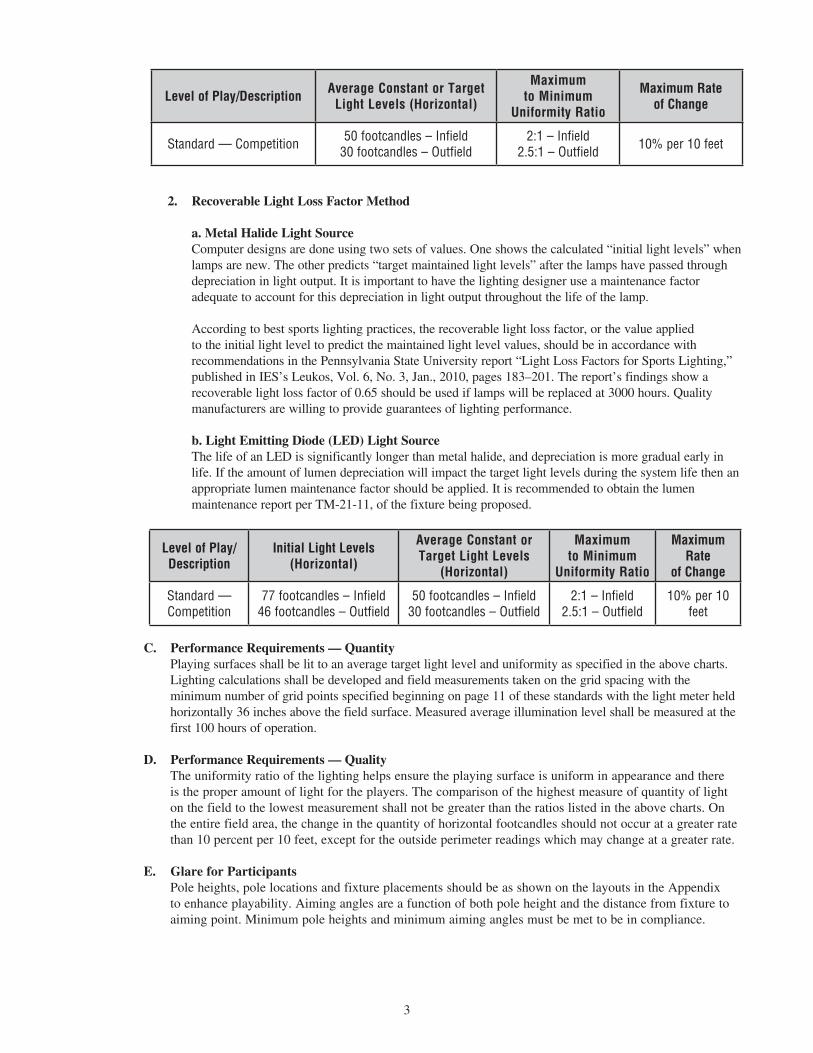
C. Performance Requirements — QuantityPlaying surfaces shall be lit to an average target light level and uniformity as specified in the above charts. Lighting calculations shall be developed and field measurements taken on the grid spacing with the minimum number of grid points specified beginning on page 11 of these standards with the light meter held horizontally 36 inches above the field surface. Measured average illumination level shall be measured at the first 100 hours of operation.
D. Performance Requirements — QualityThe uniformity ratio of the lighting helps ensure the playing surface is uniform in appearance and there is the proper amount of light for the players. The comparison of the highest measure of quantity of light on the field to the lowest measurement shall not be greater than the ratios listed in the above charts. On the entire field area, the change in the quantity of horizontal footcandles should not occur at a greater rate than 10 percent per 10 feet, except for the outside perimeter readings which may change at a greater rate.
E. Glare for ParticipantsPole heights, pole locations and fixture placements should be as shown on the layouts in the Appendix to enhance playability. Aiming angles are a function of both pole height and the distance from fixture to aiming point. Minimum pole heights and minimum aiming angles must be met to be in compliance.
Level of Play/Description Average Constant or Target Light Levels (Horizontal)
Maximum to Minimum
Uniformity Ratio
Maximum Rate of Change
Standard — Competition 50 footcandles – Infield 30 footcandles – Outfield
2:1 – Infield 2.5:1 – Outfield 10% per 10 feet
Level of Play/Description
Initial Light Levels (Horizontal)
Average Constant or Target Light Levels
(Horizontal)
Maximum to Minimum
Uniformity Ratio
Maximum Rate
of Change
Standard — Competition
77 footcandles – Infield 46 footcandles – Outfield
50 footcandles – Infield 30 footcandles – Outfield
2:1 – Infield 2.5:1 – Outfield
10% per 10 feet
4
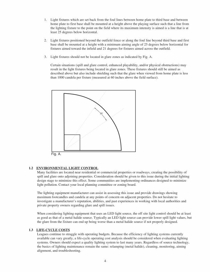
1. Light fixtures which are set back from the foul lines between home plate to third base and between home plate to first base shall be mounted at a height above the playing surface such that a line from the lighting fixture to the point on the field where its maximum intensity is aimed is a line that is at least 25 degrees below horizontal.
2. Light fixtures positioned beyond the outfield fence or along the foul line beyond third base and first base shall be mounted at a height with a minimum aiming angle of 25 degrees below horizontal for fixtures aimed toward the infield and 21 degrees for fixtures aimed across the outfield.
3. Light fixtures should not be located in glare zones as indicated by Fig. A. Certain situations (spill and glare control, enhanced playability, and/or physical obstructions) may result in the light fixtures being located in glare zones. These fixtures should still be aimed as described above but also include shielding such that the glare when viewed from home plate is less than 1000 candela per fixture (measured at 60 inches above the field surface).
1.2 ENVIRONMENTAL LIGHT CONTROLMany facilities are located near residential or commercial properties or roadways, creating the possibility of spill and glare onto adjoining properties. Consideration should be given to this issue during the initial lighting design stage to minimize this effect. Some communities are implementing ordinances designed to minimize light pollution. Contact your local planning committee or zoning board. The lighting equipment manufacturer can assist in assessing this issue and provide drawings showing maximum footcandles and candela at any points of concern on adjacent properties. Do not hesitate to investigate a manufacturer’s reputation, abilities, and past experiences in working with local authorities and private property owners regarding glare and spill issues.
When considering lighting equipment that uses an LED light source, the off site light control should be at least as good as that of a metal halide source. Typically an LED light source can provide lower spill light values, but the glare from the fixture can end up being worse than a metal halide source if not properly designed.
1.3 LIFE-CYCLE COSTSLeagues continue to struggle with operating budgets. Because the efficiency of lighting systems currently available can vary greatly, a life-cycle operating cost analysis should be considered when evaluating lighting systems. Owners should expect a quality lighting system to last many years. Regardless of source technology, the basics of lighting maintenance remain the same: relamping (metal halide), cleaning, monitoring, aiming alignment, and troubleshooting.
20˚
Fig. A.
5
These standards provide a 10-year Life-Cycle Operating Cost Evaluation form to assist with the process. Items that should be included are energy consumption based upon the facility’s expected usage, cost for spot relamping and maintenance, and any additional savings in energy or labor cost provided by automated on/off control systems. Contract price and life-cycle operating cost should both be considered in determining a lighting manufacturer for the project.
1.4 WARRANTY AND GUARANTEEProduct warranties are a good gauge of a manufacturer’s confidence in their products. Prior generation equipment can range from 5 years to 10 years, and details of covered items and conditions vary greatly. New generation technology comes with warranty periods that may extend up to 25 years and includes guaranteed light levels, parts, on-site labor, lamp replacements, energy usage, monitoring and control services, spill light control, and structural integrity. The manufacturer should provide specially-funded reserves to ensure fulfillment of the warranty for the full term. It is highly recommended you consider these all-inclusive warranties to limit your league’s future exposure to escalating costs and maintenance hassle.
LED products also range from 5 year to 10 year warranties. While the diodes themselves will typically outlast the length of the warranty, it is the other components that need to be covered in order to provide a system that will be operational for the length of the warranty. The basics of lighting maintenance remain the same: cleaning, monitoring, aiming alignment, and troubleshooting.
PART 2 – PRODUCT
2.1 LIGHTING SYSTEM CONSTRUCTIONA lighting system should consist of lighting, electrical, and structural components designed to work together as a system that is durable and provides safety features.
A. Outdoor lighting systems should consist of the following:
1. Galvanized steel poles and crossarm assembly. Wood poles are not allowed after September 1, 1994. Poles should be hot-dip galvanized to ASTM A123 standards. All accompanying hardware shall be galvanized or stainless steel. Direct burial of steel poles is not recommended because of the potential for deterioration at or below ground at critical stress points. If direct bury steel poles are used, leagues should have a foundation design completed by a structural engineer.
2. Reinforced concrete pole foundation. Foundations should provide for pole attachment a minimum of 18 inches above ground to avoid corrosive deterioration. Concrete should cure a minimum of 28 days to develop adequate strength before stress loads are applied unless a shorter cure time is approved by the structural engineer of record.
3. All ballasts, or drivers, and supporting electrical equipment shall be mounted onto the pole, away from the fixtures and crossarm to avoid problems of misalignment caused by the weight of these components. It is recommended that this equipment be placed in aluminum enclosures mounted remotely approximately 10 feet (3 meters) above grade. The enclosures shall be lockable and include safety disconnect and surge protection per circuit for each pole structure. Enclosures should be kept locked except during times of maintenance.
4. All wiring conductors above ground must be enclosed in rigid cover. It is recommended that the lighting system include a wire harness complete with an abrasion protection sleeve and strain relief.
5. The approved metal halide lamp for play is a 1500-watt ANSI code – M48/E.
6. For an efficient LED system the diodes should have a minimum color temperature of 5700 K and a CRI of 65+.
B. Manufacturing RequirementsIt is recommended that all components be designed and manufactured as a system. All luminaires, wire
6
harnesses (if provided), ballast/driver and other enclosures should be factory assembled, aimed, wired and tested for reduced installation time and trouble-free operation.
C. DurabilityIt is recommended that all exposed components be constructed of corrosion resistant material and/or coated to help prevent corrosion. Look for items like hot dip galvanizing for steel poles, stainless steel fasteners, powder coat painted aluminum, and wiring enclosed within the crossarms, conduit, pole, or electrical enclosure.
D. Lightning Protection:All outdoor structures need to be equipped with lightning protection meeting NFPA 780 standards. If lightning grounding is not integrated into the structure, it may be necessary to supplement with grounding electrodes, copper down conductors, and exothermic weld kits.
E. SafetyAll system components need to be UL Listed for the appropriate application. All electrical conductor wires for distribution of power around the playing field should be buried underground at depths provided by local code.
F. Maximum total voltage dropVoltage drop to the disconnect switch located on the poles should not exceed 3% of the rated voltage per IESNA RP-6-15, Annex D.
2.2 STRUCTURAL PARAMETERS
A. LocationPoles shall be located as shown on the drawings in the appendix to these standards. Whenever possible, poles should be located outside of fences to avoid causing an obstruction or safety hazard to the participants.
B. Foundation StrengthProject specific foundation drawings stamped by a licensed structural engineer shall be required, illustrating that the foundation design is adequate to withstand the forces imposed from the pole, fixtures, and other attachments to prevent the structure from leaning.
C. Wind Load CalculatorWind load of poles and other support structures, fixtures, brackets, arms, bases, anchorages, and foundations shall be determined based on the 50-year mean recurrent isotach wind maps for the appropriate municipality per the state building code.
D. Structural DesignThe stress analysis and safety factor of the poles shall conform to AASHTO Standard Specifications for Structural Supports for Highway Signs, Luminaires, and Traffic Signals.
E. Soil ConditionsThe design criteria for these specifications are based on soil design parameters as outlined in the geotechnical report. If a geotechnical report is not provided by the school, the foundation design shall be based on soils that meet or exceed those of a Class 5 material as defined by 2015 IBC, Table 1806.2.
7
PART 3 – EXECUTION
3.1 FIELD QUALITY CONTROLA. Illumination Measurements
Upon substantial completion of the project and in the presence of the Contractor, Project Engineer, League Representative, and Manufacturer’s Representative, illumination measurements shall be taken and verified. The illumination measurements shall be conducted in accordance with IESNA RP-6-15, Annex B.
B. Correcting Non-ConformanceIf, in the opinion of the Owner or his appointed Representative, the actual performance levels including footcandles, uniformity ratios, and maximum kilowatt consumptions are not in conformance with the requirements of the performance specifications and submitted information, the Manufacturer shall be liable to any or all of the following:
1. Manufacturer shall, at his expense, provide and install any necessary additional fixtures to meet the minimum lighting standards. The Manufacturer shall also either replace the existing poles to meet the new wind load (EPA) requirements or verify by certification by a licensed structural engineer that the existing poles will withstand the additional wind load.
2. Manufacturer shall minimize the Owner’s additional long term fixture maintenance and energy consumption costs created by the additional fixtures by reimbursing the Owner the amount of $1,000 (one thousand dollars) for each additional fixture required.
3. Manufacturer shall remove the entire unacceptable lighting system and install a new lighting system to meet the specifications.
3.2 ONGOING QUALITY ASSURANCEA. Full light and safety audits should be performed every year. See Lighting Safety Audit at the back of
these standards.
8
II. Desirable FeaturesThe following practices are recommended for increasing the lighting system performance.
4.1 CONTROL AND MONITORING SYSTEMA remote control and monitoring system will provide ease of operation and management for your facility. Manufacturers providing systems with a long-term warranty of at least 10 years will use this system to ensure your lighting performs as required.
A. Remote MonitoringMonitoring systems can check the lighting system each time it is turned on for luminaire outages. When an outage is detected, the manufacturer should notify the owner so that appropriate maintenance can be scheduled.
B. Remote Lighting ControlLighting control systems allow owners and users with a security code to schedule on/off system operation in a variety of methods including web sites, phone, app, fax, or email. Look for manufacturers that provide trained staff available 24/7 to provide scheduling support. Also evaluate features such as memory back up in the event of power outages.
C. Management ToolsSome manufacturers provide a web-based database of actual field usage and provide reports by facility and user group.
D. Communication CostsLeagues should request that manufacturers include communication costs for operating the control and monitoring system for the life of the lighting system.
4.2 AUXILIARY BRACKETSSports lighting manufacturers can provide accommodations for mounting auxiliary equipment, such as speakers and security lights, on sport lighting poles. This ensures poles will be sized to accommodate the weight, dimensions, and EPA of the additional equipment. Brackets shall be welded to the pole and fabricated from hot-dip galvanized steel with a covered hand hole access and internal wiring in the pole.
4.3 FIELD PERIMETER LIGHTINGThe parking areas, major areas utilized for passage, and areas immediately bordering the facilities should be lighted. The spill light from the playing field may provide illumination for some of these areas when the field is in use. When a sports field is not in use its sports lights should be turned off. Then other security lighting would be needed. For appropriate levels, see local codes. Care should be taken to eliminate darkly shadowed areas.
For additional information, contact: Little League® InternationalPO Box 3485
Williamsport, PA 17701570/326-1921
Fax: 570/326-1074
9
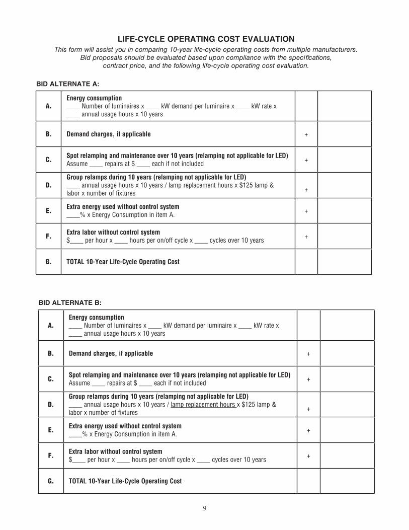
LIFE-CYCLE OPERATING COST EVALUATIONThis form will assist you in comparing 10-year life-cycle operating costs from multiple manufacturers.
Bid proposals should be evaluated based upon compliance with the specifications, contract price, and the following life-cycle operating cost evaluation.
BID ALTERNATE A:
A.Energy consumption____ Number of luminaires x ____ kW demand per luminaire x ____ kW rate x ____ annual usage hours x 10 years
B. Demand charges, if applicable +
C. Spot relamping and maintenance over 10 years (relamping not applicable for LED)Assume ____ repairs at $ ____ each if not included +
D.Group relamps during 10 years (relamping not applicable for LED)____ annual usage hours x 10 years / lamp replacement hours x $125 lamp & labor x number of fixtures +
E. Extra energy used without control system____% x Energy Consumption in item A. +
F. Extra labor without control system$____ per hour x ____ hours per on/off cycle x ____ cycles over 10 years +
G. TOTAL 10-Year Life-Cycle Operating Cost
BID ALTERNATE B:
A.Energy consumption____ Number of luminaires x ____ kW demand per luminaire x ____ kW rate x ____ annual usage hours x 10 years
B. Demand charges, if applicable +
C. Spot relamping and maintenance over 10 years (relamping not applicable for LED)Assume ____ repairs at $ ____ each if not included +
D.Group relamps during 10 years (relamping not applicable for LED)____ annual usage hours x 10 years / lamp replacement hours x $125 lamp & labor x number of fixtures +
E. Extra energy used without control system____% x Energy Consumption in item A. +
F. Extra labor without control system$____ per hour x ____ hours per on/off cycle x ____ cycles over 10 years +
G. TOTAL 10-Year Life-Cycle Operating Cost
10
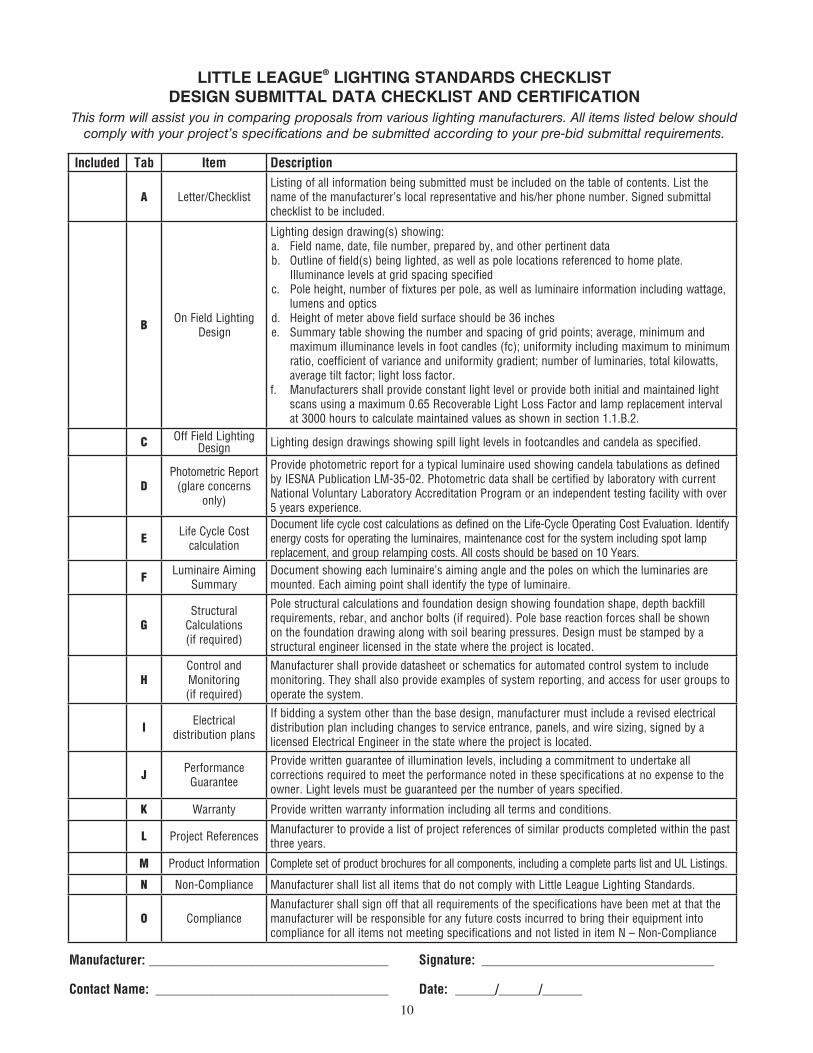
LITTLE LEAGUE® LIGHTING STANDARDS CHECKLIST DESIGN SUBMITTAL DATA CHECKLIST AND CERTIFICATION
This form will assist you in comparing proposals from various lighting manufacturers. All items listed below should comply with your project’s specifications and be submitted according to your pre-bid submittal requirements.
Included Tab Item Description
A Letter/ChecklistListing of all information being submitted must be included on the table of contents. List the name of the manufacturer’s local representative and his/her phone number. Signed submittal checklist to be included.
B On Field Lighting
Design
Lighting design drawing(s) showing: a. Field name, date, file number, prepared by, and other pertinent datab. Outline of field(s) being lighted, as well as pole locations referenced to home plate.
Illuminance levels at grid spacing specifiedc. Pole height, number of fixtures per pole, as well as luminaire information including wattage,
lumens and opticsd. Height of meter above field surface should be 36 inchese. Summary table showing the number and spacing of grid points; average, minimum and
maximum illuminance levels in foot candles (fc); uniformity including maximum to minimum ratio, coefficient of variance and uniformity gradient; number of luminaries, total kilowatts, average tilt factor; light loss factor.
f. Manufacturers shall provide constant light level or provide both initial and maintained light scans using a maximum 0.65 Recoverable Light Loss Factor and lamp replacement interval at 3000 hours to calculate maintained values as shown in section 1.1.B.2.
C Off Field Lighting Design Lighting design drawings showing spill light levels in footcandles and candela as specified.
DPhotometric Report
(glare concerns only)
Provide photometric report for a typical luminaire used showing candela tabulations as defined by IESNA Publication LM-35-02. Photometric data shall be certified by laboratory with current National Voluntary Laboratory Accreditation Program or an independent testing facility with over 5 years experience.
E Life Cycle Cost calculation
Document life cycle cost calculations as defined on the Life-Cycle Operating Cost Evaluation. Identify energy costs for operating the luminaires, maintenance cost for the system including spot lamp replacement, and group relamping costs. All costs should be based on 10 Years.
F Luminaire Aiming Summary
Document showing each luminaire’s aiming angle and the poles on which the luminaries are mounted. Each aiming point shall identify the type of luminaire.
GStructural
Calculations (if required)
Pole structural calculations and foundation design showing foundation shape, depth backfill requirements, rebar, and anchor bolts (if required). Pole base reaction forces shall be shown on the foundation drawing along with soil bearing pressures. Design must be stamped by a structural engineer licensed in the state where the project is located.
HControl and Monitoring (if required)
Manufacturer shall provide datasheet or schematics for automated control system to include monitoring. They shall also provide examples of system reporting, and access for user groups to operate the system.
I Electrical distribution plans
If bidding a system other than the base design, manufacturer must include a revised electrical distribution plan including changes to service entrance, panels, and wire sizing, signed by a licensed Electrical Engineer in the state where the project is located.
J Performance Guarantee
Provide written guarantee of illumination levels, including a commitment to undertake all corrections required to meet the performance noted in these specifications at no expense to the owner. Light levels must be guaranteed per the number of years specified.
K Warranty Provide written warranty information including all terms and conditions.
L Project References Manufacturer to provide a list of project references of similar products completed within the past three years.
M Product Information Complete set of product brochures for all components, including a complete parts list and UL Listings.
N Non-Compliance Manufacturer shall list all items that do not comply with Little League Lighting Standards.
O Compliance Manufacturer shall sign off that all requirements of the specifications have been met at that the manufacturer will be responsible for any future costs incurred to bring their equipment into compliance for all items not meeting specifications and not listed in item N – Non-Compliance
Manufacturer: ____________________________________ Signature: ___________________________________
Contact Name: ___________________________________ Date: ______/______/______
11
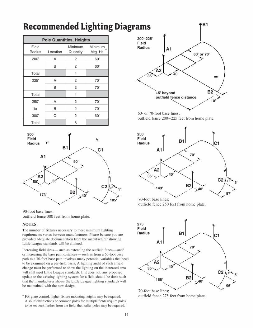
The number of fixtures necessary to meet minimum lighting requirements varies between manufacturers. Please be sure you are provided adequate doc u men ta tion from the manufacturer showing Little League stan dards will be attained.
Increasing field sizes — such as extending the outfield fence — and/or increasing the base path distances — such as from a 60-foot base path to a 70-foot base path involves many potential variables that need to be examined on a per-field basis. A lighting audit of such a field change must be performed to show the lighting on the increased area will still meet Little League standards. If it does not, any proposed update to the existing lighting system for a field should be done such that the manufacturer shows the Little League lighting standards will be maintained with the new design.
† For glare control, higher fixture mounting heights may be required. Also, if obstructions or common poles for multiple fields require poles to be set back farther from the field, then taller poles may be required.
NOTES:
Pole Quantities, Heights
Field Minimum Minimum Radius Location Quantity Mtg. Ht.
200' A 2 60'
B 2 60'
Total 4
225' A 2 70'
B 2 70'
Total 4
250' A 2 70'
to B 2 70'
300' C 2 60'
Total 6
A1
B1
A2
B2
35' 40'
+5' beyond outfield fence distance
10'
A1
B1 C1
C2B2
50'A2
55'
40'105'
5'
173'
90'
60' or 70'
Recommended Lighting Diagrams
60- or 70-foot base lines; outfield fence 200 – 225 feet from home plate.
90-foot base lines; outfield fence 300 feet from home plate.
†
A1
B1 C1
C2B2
35'
A240'
40'87'
5'
143'
70'
70-foot base lines; outfield fence 250 feet from home plate.
A1
B1 C1
C2B2
35'
A240'
40'96'
5' 155'
70'
70-foot base lines; outfield fence 275 feet from home plate.
200'-225'Field Radius
250'Field Radius
275'Field Radius
300'Field Radius
12
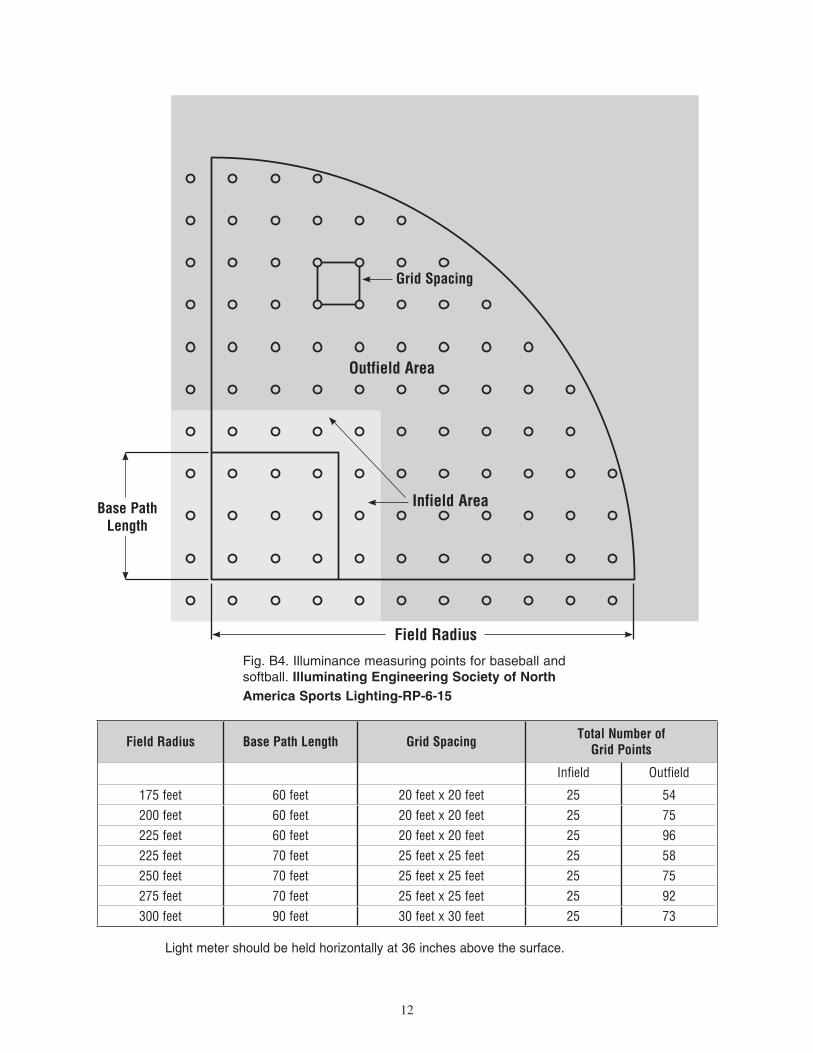
Fig. B4. Illuminance measuring points for baseball and softball. Illuminating Engineering Society of North America Sports Lighting-RP-6-15
Grid Spacing
Outfield Area
Infield Area
Field Radius
Base PathLength
Light meter should be held horizontally at 36 inches above the surface.
Field Radius Base Path Length Grid Spacing Total Number of Grid Points
Infield Outfield
175 feet 60 feet 20 feet x 20 feet 25 54200 feet 60 feet 20 feet x 20 feet 25 75225 feet 60 feet 20 feet x 20 feet 25 96225 feet 70 feet 25 feet x 25 feet 25 58250 feet 70 feet 25 feet x 25 feet 25 75275 feet 70 feet 25 feet x 25 feet 25 92300 feet 90 feet 30 feet x 30 feet 25 7396'
13
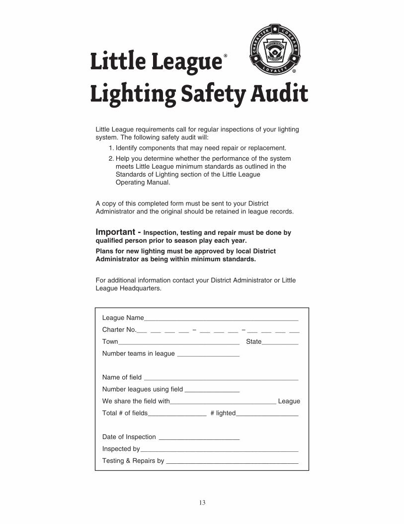
Little League®
Lighting Safety AuditLittle League requirements call for regular inspections of your lighting system. The following safety audit will:
1. Identify components that may need repair or replacement.
2. Help you determine whether the performance of the system meets Little League minimum standards as outlined in the Standards of Lighting section of the Little League Operating Manual.
A copy of this completed form must be sent to your District Administrator and the original should be retained in league records.
Important - Inspection, testing and repair must be done by qualified person prior to season play each year.
Plans for new lighting must be approved by local District Administrator as being within minimum standards.
For additional information contact your District Administrator or Little League Headquarters.
League Name __________________________________________
Charter No.___ ___ ___ ___ – ___ ___ ___ – ___ ___ ___ ___
Town _________________________________ State __________
Number teams in league _________________
Name of field __________________________________________
Number leagues using field _______________
We share the field with_____________________________ League
Total # of fields ________________ # lighted _________________
Date of Inspection ______________________
Inspected by ___________________________________________
Testing & Repairs by ____________________________________
14
1
5
11
19
28
37
1
6
11
16
21
2
6
12
20
29
38
2
7
12
17
22
3
7
13
21
30
39
3
8
13
18
23
8
14
22
31
40
4
9
14
19
24
9
15
23
32
41
5
10
15
20
25
10
16
24
33
42
47
52
58
64
70
17
25
34
43
48
53
59
65
71
26
35
44
49
54
60
66
72
27
36
45
50
55
61
67
73
46
51
56
62
68
74
57
63
69
75
4
18
60'Basepath
90'Basepath
20'
20'
30'
30'
Infield Area Outfield Area
70'Basepath
25'
25'
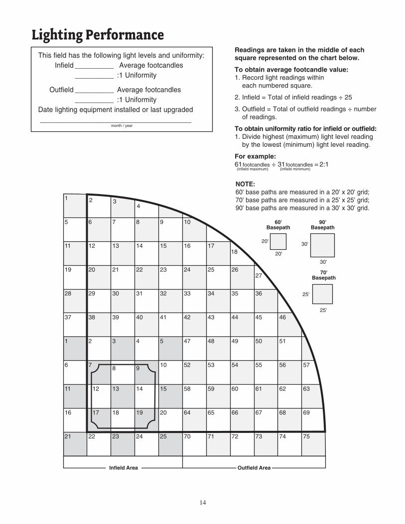
Readings are taken in the middle of each square represented on the chart below.
To obtain average footcandle value: 1. Record light readings within each numbered square.
2. Infield = Total of infield readings ÷ 25
3. Outfield = Total of outfield readings ÷ number of readings.
To obtain uniformity ratio for infield or outfield: 1. Divide highest (maximum) light level reading by the lowest (minimum) light level reading.
For example: 61footcandles ÷ 31footcandles = 2:1 (infield maximum) (infield minimum)
Lighting PerformanceThis field has the following light levels and uniformity: Infield __________ Average footcandles __________ :1 Uniformity
Outfield __________ Average footcandles __________ :1 UniformityDate lighting equipment installed or last upgraded _______________________________________
month / year
NOTE: 60' base paths are measured in a 20' x 20' grid; 70' base paths are measured in a 25' x 25' grid; 90' base paths are measured in a 30' x 30' grid.
15
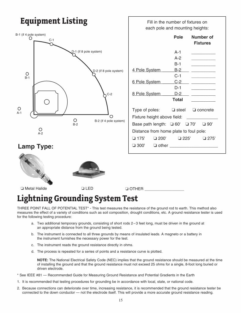
Lamp Type:
o Metal Halide o LED o OTHER __________________
Fill in the number of fixtures oneach pole and mounting heights:
Pole Number of Fixtures
A-1 __________ A-2 __________ B-1 __________4 Pole System _____B-2 __________ C-1 __________6 Pole System _____C-2 __________ D-1 __________8 Pole System _____D-2 __________ Total __________
Type of poles: o steel o concrete
Fixture height above field: _____________
Base path length: o 60' o 70' o 90'
Distance from home plate to foul pole:
o 175' o 200' o 225' o 275'
o 300' o other ____________________
Equipment Listing
THREE POINT FALL OF POTENTIAL TEST* - This test measures the resistance of the ground rod to earth. This method also measures the effect of a variety of conditions such as soil composition, drought conditions, etc. A ground resistance tester is used for the following testing procedure:
a. Two additional temporary grounds, consisting of short rods 2 – 3 feet long, must be driven in the ground at an appropriate distance from the ground being tested.
b. The instrument is connected to all three grounds by means of insulated leads. A magneto or a battery in the instrument furnishes the necessary power for the test.
c. The instrument reads the ground resistance directly in ohms.
d. The process is repeated for a series of points and a resistance curve is plotted. NOTE: The National Electrical Safety Code (NEC) implies that the ground resistance should be measured at the time of installing the ground and that the ground resistance must not exceed 25 ohms for a single, 8-foot long buried or driven electrode.
* See IEEE #81 — Recommended Guide for Measuring Ground Resistance and Potential Gradients in the Earth
1. It is recommended that testing procedures for grounding be in accordance with local, state, or national code.
2. Because connections can deteriorate over time, increasing resistance, it is recommended that the ground resistance tester be connected to the down conductor — not the electrode itself. This will provide a more accurate ground resistance reading.
Lightning Grounding System Test
B-1 (if 4 pole system)
D-1 (if 8 pole system)
D-2 (if 8 pole system)
B-2 (if 4 pole system)
C-1
C-2
B-1
A-1
A-2
B-2
16* These tests and/or repairs require the services of a qualified electrician.
WA
RN
ING
!! T
urn
off
ele
ctri
city
at
po
wer
so
urc
e an
d a
t sa
fety
dis
con
nec
t o
n t
he
po
le.
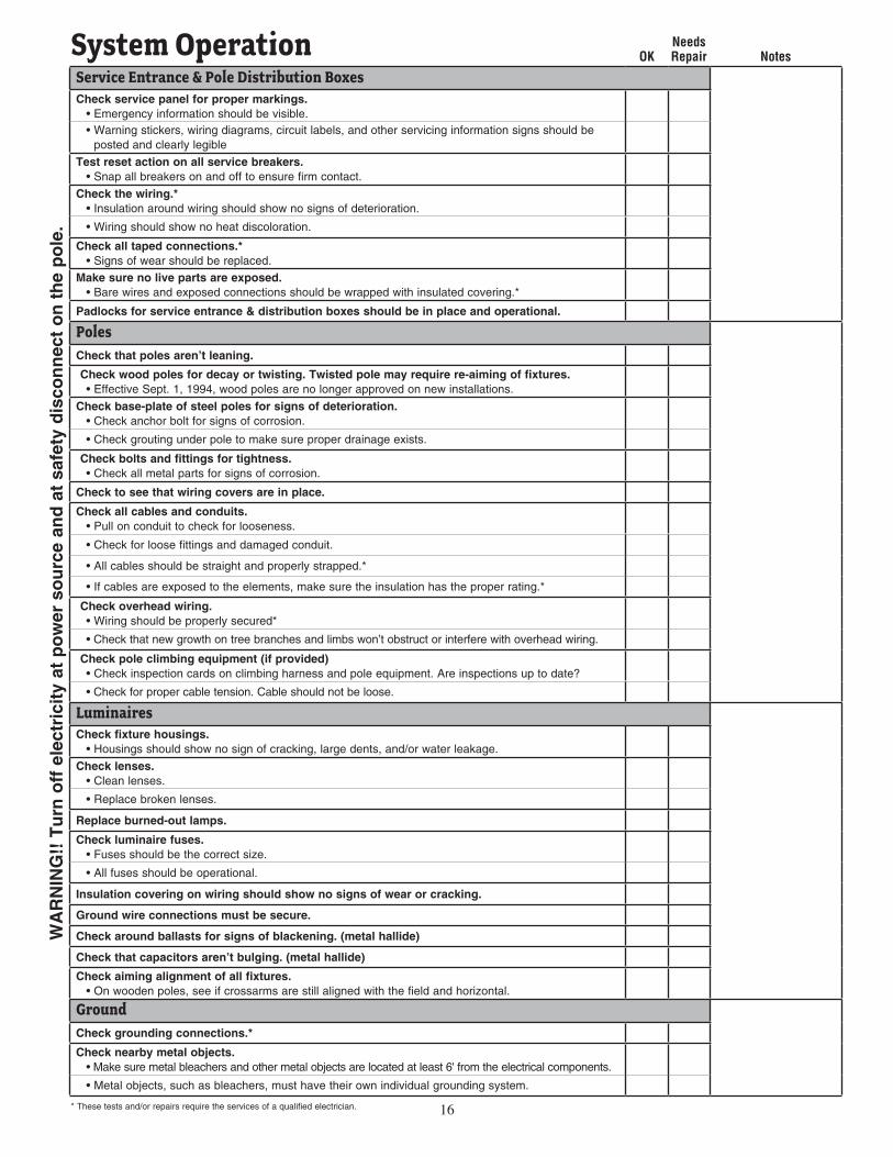
System Operation OKNeeds Repair Notes
Service Entrance & Pole Distribution BoxesCheck service panel for proper markings. • Emergency information should be visible. • Warning stickers, wiring diagrams, circuit labels, and other servicing information signs should be
posted and clearly legible
Test reset action on all service breakers. • Snap all breakers on and off to ensure firm contact.
Check the wiring.* • Insulation around wiring should show no signs of deterioration.
• Wiring should show no heat discoloration.
Check all taped connections.* • Signs of wear should be replaced.
Make sure no live parts are exposed. • Bare wires and exposed connections should be wrapped with insulated covering.*
Padlocks for service entrance & distribution boxes should be in place and operational.
PolesCheck that poles aren’t leaning.
Check wood poles for decay or twisting. Twisted pole may require re-aiming of fixtures. • Effective Sept. 1, 1994, wood poles are no longer approved on new installations.
Check base-plate of steel poles for signs of deterioration. • Check anchor bolt for signs of corrosion.
• Check grouting under pole to make sure proper drainage exists.
Check bolts and fittings for tightness. • Check all metal parts for signs of corrosion.
Check to see that wiring covers are in place.
Check all cables and conduits. • Pull on conduit to check for looseness.
• Check for loose fittings and damaged conduit.
• All cables should be straight and properly strapped.*
• If cables are exposed to the elements, make sure the insulation has the proper rating.*
Check overhead wiring. • Wiring should be properly secured*
• Check that new growth on tree branches and limbs won’t obstruct or interfere with overhead wiring.
Check pole climbing equipment (if provided) • Check inspection cards on climbing harness and pole equipment. Are inspections up to date?
• Check for proper cable tension. Cable should not be loose.
LuminairesCheck fixture housings. • Housings should show no sign of cracking, large dents, and/or water leakage.
Check lenses. • Clean lenses.
• Replace broken lenses.
Replace burned-out lamps.
Check luminaire fuses. • Fuses should be the correct size.
• All fuses should be operational.
Insulation covering on wiring should show no signs of wear or cracking.
Ground wire connections must be secure.
Check around ballasts for signs of blackening. (metal hallide)
Check that capacitors aren’t bulging. (metal hallide)
Check aiming alignment of all fixtures. • On wooden poles, see if crossarms are still aligned with the field and horizontal.
GroundCheck grounding connections.*
Check nearby metal objects. • Make sure metal bleachers and other metal objects are located at least 6' from the electrical components.
• Metal objects, such as bleachers, must have their own individual grounding system.

M-1425-enUS-17
For additional information contact:LITTLE LEAGUE® INTERNATIONAL
PO Box 3485 Williamsport, PA 17701
570/326-1921 Fax: 570/326-1074