Embed Size (px)
Citation preview

2017 International
Perforating Safety Forum
Experience with calculation of the RF Exclusion Zones
according to the new API RP67 safety distance
recommendations
AUTHORS: Frank Preiss, Andreas Zemla - DynaEnergeticsIPSF 17-02

AgendaIPSF 17-02
New API RP 67 – 7.3.6 Electric Detonators
IME SLP 20 – Part III – Tables of Recommended Safe Distances from RF
Sources for 50 Ohm Oilfield Resistorized Electric Detonators
Test Setup for Radiated Electromagnetic Susceptibility
Result Summary according HERO Specifications
Result Comparison of Radiated Electromagnetic Susceptibility for a Safe
Detonator
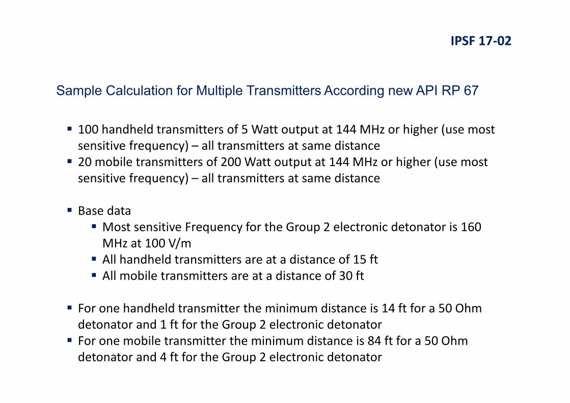
Sample Calculation for Multiple Transmitters According new API RP 67
Additional Testing
Conclusions

TITLEIPSF 17-02
New Detonator Classification
Group 1 (equivalent to 50 Ohm Resistorized Detonators) May contain primary explosives
No fire current of min 200mA
Follow SLP 20 guidance on rf exclusion distances
Group 2 (Safe Detonators) May contain primary explosives
No fire voltage of min 25 vac/vdc
Manufacturer to publish safe distances for all frequencies according to SLP 20 – the user
will have to determine the safety distance dependent on the actual well site situation
Manufacturer to provide a sample calculation of rf exclusion distances for multiple
transmitters
No single point of failure within the detonator may result in an unintended initiation
New API RP 67 – 7.3.6 Electric Detonators

TITLEIPSF 17-02
Group 3 (Immune Detonators) No primary explosives
Immune to rf energies – no exclusion zone required
No single point of failure within the detonator may result in an unintended initiation
Any detonator attachment that changes the characteristics of the assembly
may change the group
New API RP 67 – 7.3.6 Electric Detonators

TITLEIPSF 17-02
Safety distances are based on minimum safety levels
Examples for safely distances for 50 Ohm oilfield resistorized detonators
Standard AM Transmitter – 3,391 ft
FM Transmitter – 2,120 ft
Television Transmitter – 1,511 ft to 4,800 ft (dependent on Channel)
Amateur/Citizen’s Band – 878 ft
Cellular Telephone – 5 ft
Cellular Telephone Transmitter – 54 ft
Maritime Radionavigation Radar (Commercial Shipping) – 190 ft
IME SLP 20 – Part IIITables of Recommended Safe Distances from RF Sources for 50 Ohm Oilfield Resistorized Electric Detonators

TITLEIPSF 17-02
Tests were done in accordance with the HERO SAFE ORDANANCE
specification (MIL Standard HDBK-240 3.2.9) for RF immunity to tested levels
The devices under Test are assembled with a fusehead without primer
A temperature sensor measures the heat of the filament wire of the fuse
head
The temperature is calibrated towards current flows
The devices are exposed to the RF-field in vertical and horizontal
polarization and the temperature increase of the filament wire is
measured
The test is done in two wire configurations, stretched and folded dipole
Test pass criteria
The measured temperature is below the safety reference temperature
If the temperature is too high the field strength is reduced and the
measurement repeated until a safe field strength is found
Test Setup for Radiated Electromagnetic Susceptibility

TITLEIPSF 17-02
Result Summary according HERO Specifications

TITLEIPSF 17-02
Result Comparison of Radiated Electromagnetic Susceptibility
Recommended Minimum Distance
Transmitted Power 50 Ω Detonator Tested Group 2 Electronic Detonator
[Watt] [FT] [FT]
Standard AM Transmitter 50,000 3,391 17
FM Transmitter 100,000 2,120 24
Television Transmitter 100,000 1,511 to 4,800 (dependent on Channel) 73 to 77 (dependent on Channel)
CB Radio 4 42 0
Amateur/Citizen’s Band 1,500 878 4
Cellular Telephone 3 5 0
Cellular Telephone Transmitter 500 54 3
Maritime Radionavigation
Radar (Commercial Shipping)50,000 190 17
TITLEIPSF 17-02
100 handheld transmitters of 5 Watt output at 144 MHz or higher (use most
sensitive frequency) – all transmitters at same distance
20 mobile transmitters of 200 Watt output at 144 MHz or higher (use most
sensitive frequency) – all transmitters at same distance
Base data
Most sensitive Frequency for the Group 2 electronic detonator is 160
MHz at 100 V/m
All handheld transmitters are at a distance of 15 ft
All mobile transmitters are at a distance of 30 ft
For one handheld transmitter the minimum distance is 14 ft for a 50 Ohm
detonator and 1 ft for the Group 2 electronic detonator
For one mobile transmitter the minimum distance is 84 ft for a 50 Ohm
detonator and 4 ft for the Group 2 electronic detonator
Sample Calculation for Multiple Transmitters According new API RP 67

TITLEIPSF 17-02
According to SLP 20 the following equation has to be met to assure a very
low likelihood of an inadvertent initiation
(E1/E1max)2 + (E2/E2max)
2 + (E3/E3max)2 + … + (En/Enmax)
2 < 1
En are the measured or computed electric field strengths at the detonator
location with respect to the RF sources
Enmax are the maximum acceptable electric field strengths for that frequency
from the above plot
E =7,02
ERP is the power of the transmitter
D is the distance from the transmitter
Sample Calculation for Multiple Transmitters According new API RP 67

TITLEIPSF 17-02
Handheld Transmitter
ERP = 5 W
D = 5 m (approximately 15 ft)
E1 to E100 for the handheld transmitters at 15 ft is 3.14 V/m
Mobile Transmitter
ERP = 200 W
D = 10 m (approximately 30 ft)
E101 to E120 for the mobile transmitters at 30 ft is 9.93 V/m
Sample Calculation for Multiple Transmitters According new API RP 67

TITLEIPSF 17-02
Emax for all handheld and mobile transmitters for the 50 Ohm detonator is
1 V/m at the most sensitive frequency of 28 MHz and 5 V/m at the
frequency of 160 MHz (for comparison only)
Emax for all handheld and mobile transmitters for the Group 2 electronic
detonator is 100 V/m at the most sensitive frequency of 160 MHz
(E1/E1max)2 + (E2/E2max)
2 + (E3/E3max)2 + … + (En/Enmax)
2 < 1
The result for the 50 Ohm detonator is 2956.824 for 1 V/m and 118.273
for 5 V/m, both of which are bigger than 1 resulting in unsafe situations
The result for the Group 2 electronic detonator is 0.295 which is smaller
than 1 resulting in a safe situation
Sample Calculation for Multiple Transmitters According new API RP 67

TITLEIPSF 17-02
Optional scenario
Handheld Transmitter
ERP = 5 W
D = 33 m (approximately 100 ft)
E1 to E100 for the handheld transmitters at 15 ft is 3.14 V/m
Mobile Transmitter
ERP = 200 W
D = 33 m (approximately 100 ft)
E101 to E120 for the mobile transmitters at 30 ft is 9.93 V/m
The result for the 50 Ohm detonator is 203.638 for 1 V/m and 8.146 for 5
V/m, both of which are bigger than 1 resulting in unsafe situations
The result for the Group 2 electronic detonator is 0.020 which is smaller
than 1 resulting in a safe situation
Sample Calculation for Multiple Transmitters According new API RP 67
TITLEIPSF 17-02
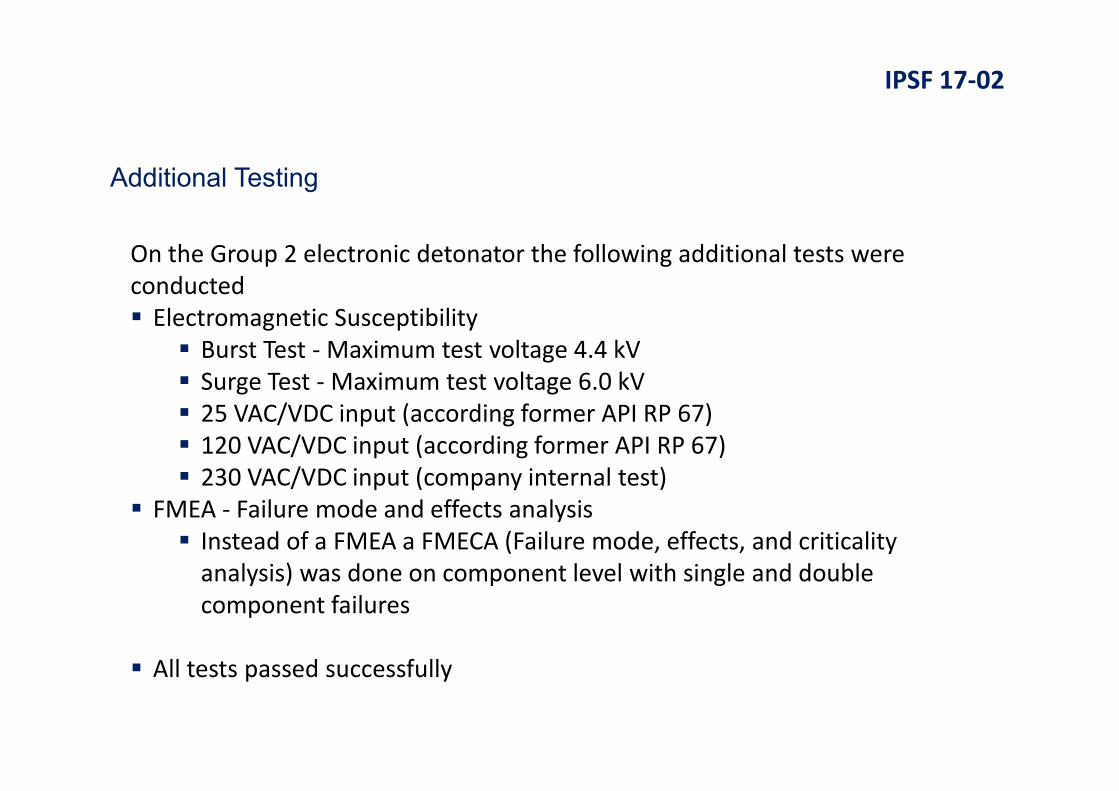
On the Group 2 electronic detonator the following additional tests were
conducted
Electromagnetic Susceptibility
Burst Test - Maximum test voltage 4.4 kV
Surge Test - Maximum test voltage 6.0 kV
25 VAC/VDC input (according former API RP 67)
120 VAC/VDC input (according former API RP 67)
230 VAC/VDC input (company internal test)
FMEA - Failure mode and effects analysis
Instead of a FMEA a FMECA (Failure mode, effects, and criticality
analysis) was done on component level with single and double
component failures
All tests passed successfully
Additional Testing

TITLEIPSF 17-02
The base electromagnetic susceptibility tests is cumbersome to conduct,
but once done the measured safe field strength’ at the individual
frequencies are known and the safe operating environment can be
calculated
With the present well site environment a safety assessment is imperative
Contact your detonator or system manufacturer in case you have any
questions
Conclusions

QUESTIONS?
THANK YOU!
Experience with calculation of the RF Exclusion Zones according to the new API RP67 safety distance
recommendations
AUTHORS: Frank Preiss, Andreas Zemla - DynaEnergetics
2017 International Perforating
Safety Forum
IPSF 17-02