Embed Size (px)
Citation preview

O W N E R H A N D B O O K
F I A T F R E E M O N TENGLISH
The data contained in this publication is intended merely as a guide. FIAT reserves the right to modify the models and versions described in this booklet at any time for technical and commercial reasons.
If you have any further questions please consult your FIAT dealer. Printed in recycled paper without chlorine.
1500080_14_FIAT_Freemont_OM_cover.indd 1 8/27/13 3:02 PM

We really know your car because we invented, designedand built it: we know every single detail. At
Fiat Service authorised workshops you can findtechnicians who are trained by us, offering quality and
professionalism for all your service requirements.
Fiat workshops are always close to you for yourservicing operations, repairs and seasonal checks andour experts will offer practical recommendations for
keeping your car in the best possible condition.When you use Genuine Parts you keep the reliability,
comfort and performance features of your new carover time.
Always ask for Genuine Parts and insist on thembeing fitted to your car. We recommend them because
we know they are derived from our continuedcommitment to research and development and our use
of highly innovative technologies.
For these reasons, you can rely on Genuine Partsbecause they are the only ones designed specifically
for your car.
WHY CHOOSE GENUINE PARTS
1500080_14_FIAT_Freemont_OM_cover.indd 2 8/27/13 3:02 PM
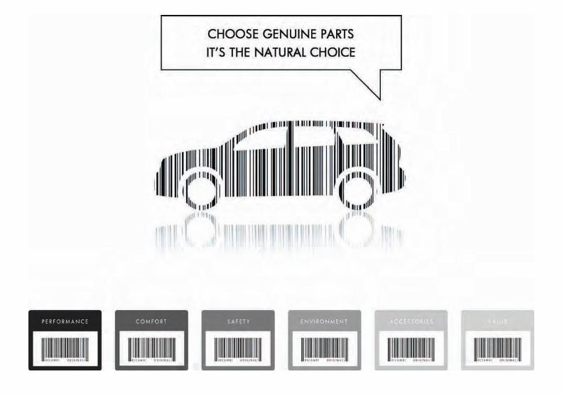

All our Genuine Parts undergo rigorous testing, both in design and build stages, by specialists who check the use ofcutting-edge materials and test their reliability.
This guarantees performance and safety in the long term for both you and the passengers in your automobile.
Always insist on a Genuine Part and check that it has been used.

Dear Customer,
Thank you for choosing Fiat and congratulations on your choice of a Fiat Freemont.
We have written this handbook to help you get to know all your car and use it in the best possible way.
You should read it right through before taking to the road for the first time.
You will find information, tips and important warnings regarding the driving of your car to help you get the most from thetechnological features of your Fiat.
Carefully read the warnings and indications marked with the following symbols:
personal safety;
car safety;
environmental protection.
The enclosed Warranty Booklet lists the services that Fiat offers to its customers:
• the Warranty Certificate with terms and conditions for maintaining its validity
• the range of additional services available to Fiat customers.
Enjoy the read. Happy motoring!
This Owner Handbook describes all versions of the Fiat Freemont; please consider only the information relevantto your version, engine and configuration.


KNOWING YOUR VEHICLEINTRODUCTIONCongratulations on selecting your new FIAT vehicle. Beassured that it represents precision workmanship, dis-tinctive styling, and high quality - all essentials that aretraditional to our vehicles.
Before you start to drive this vehicle, read this Owner'sManual and all the supplements. Be sure you are familiarwith all vehicle controls, particularly those used forbraking, steering, and transmission shifting. Learn howyour vehicle handles on different road surfaces. Yourdriving skills will improve with experience, but as indriving any vehicle, take it easy as you begin. Alwaysobserve local laws wherever you drive.
NOTE: After reviewing the owner information,it should be stored in the vehicle for convenientreferencing and remain with the vehicle whensold.
Failure to operate this vehicle correctly may result inloss of control or a collision.
Operating this vehicle at excessive speeds or whileintoxicated may result in loss of control, collision withother vehicles or objects, going off the road, or over-turning; any of which may lead to serious injury ordeath. Also, failure to use seat belts subjects the driverand passengers to a greater risk of injury or death.
To keep your vehicle running at its best, have yourvehicle serviced at recommended intervals by an au-thorized dealer who has the qualified personnel, specialtools, and equipment to perform all service.
The manufacturer and its distributors are vitally inter-ested in your complete satisfaction with this vehicle.If you encounter a service or warranty problem, whichis not resolved to your satisfaction, discuss the matterwith your dealer's management.
Your authorized dealer will be happy to assist you withany questions about your vehicle.
1
KNOWINGYOURVEHICLE
SAFETY
STARTINGANDDRIVING
WARNINGLIGHTSANDMESSAGES
IN ANEMERGENCY
SERVICINGAND CARE
TECHNICALSPECIFICATIONS
CONTENTS

IMPORTANT NOTICEALL MATERIAL CONTAINED IN THIS PUBLICA-TION IS BASED ON THE LATEST INFORMATIONAVAILABLE AT TIME OF PUBLICATION APPROVAL.THE RIGHT IS RESERVED TO PUBLISH REVISIONSAT ANY TIME.
This Owner's Manual has been prepared with theassistance of service and engineering specialists toacquaint you with the operation and maintenance ofyour new vehicle. It is supplemented by a WarrantyInformation Booklet and various customer-orienteddocuments. You are urged to read these publicationscarefully. Following the instructions and recommenda-tions in this Owner's Manual will help assure safe andenjoyable operation of your vehicle.
After you have read the Owner’s Manual, it should bestored in the vehicle for convenient reference andremain with the vehicle when sold.
The manufacturer reserves the right to make changesin design and specifications, and/or to make additionsto or improvements in its products without imposingany obligations upon itself to install them on productspreviously manufactured.
The Owner's Manual illustrates and describes the fea-tures that are standard or available as extra cost op-tions. Therefore, some of the equipment and accesso-ries in this publication may not appear on your vehicle.
NOTE: Be sure to read the Owner's Manual first beforedriving your vehicle and before attaching or installingparts/accessories or making other modifications to thevehicle.
In view of the many replacement parts and accessoriesfrom various manufacturers available on the market,the manufacturer cannot be certain that the drivingsafety of your vehicle will not be impaired by theattachment or installation of such parts. Even if suchparts are officially-approved (for example, by a generaloperating permit for the part or by constructing thepart in an officially approved design), or if an individualoperating permit was issued for the vehicle after theattachment or installation of such parts, it cannot beimplicitly assumed that the driving safety of your ve-hicle is unimpaired. Therefore, neither experts norofficial agencies are liable. The manufacturer only as-sumes responsibility when parts, which are expresslyauthorized or recommended by the manufacturer, areattached or installed at an authorized dealer. The sameapplies when modifications to the original conditionare subsequently made on the manufacturer's vehicles.
2
KNOWINGYOUR
VEHICLE
SAFETY
STARTINGAND
DRIVING
WARNINGLIGHTS
ANDMESSAGES
IN ANEMERGENCY
SERVICINGAND CARE
TECHNICALSPECIFICATIONS
CONTENTS
Your warranties do not cover any part that the manu-facturer did not supply. Nor do they cover the cost ofany repairs or adjustments that might be caused orneeded because of the installation or use of non-manufacturer parts, components, equipment, materi-als, or additives. Nor do your warranties cover thecosts of repairing damage or conditions caused by anychanges to your vehicle that do not comply with themanufacturers specifications.
Original parts and accessories and other productsapproved by the manufacturer, including qualified ad-vice, are available at your authorized dealer.
When it comes to service, remember that your autho-rized dealer knows your vehicle best, has the factory-trained technicians and genuine parts, and is interestedin your satisfaction.
Copyright © FIAT Group Automobiles S.p.A.
3
KNOWINGYOURVEHICLE
SAFETY
STARTINGANDDRIVING
WARNINGLIGHTSANDMESSAGES
IN ANEMERGENCY
SERVICINGAND CARE
TECHNICALSPECIFICATIONS
CONTENTS

HOW TO USE THIS MANUALConsult the Table of Contents to determine whichsection contains the information you desire.
Since the specification of your vehicle depends on theitems of equipment ordered, certain descriptions andillustrations may differ from your vehicle's equipment.
The detailed index at the back of this Owner's Manualcontains a complete listing of all subjects.
Consult the following table for a description of thesymbols that may be used on your vehicle or through-out this Owner's Manual: (fig. 1)
(fig. 1)
4
KNOWINGYOUR
VEHICLE
SAFETY
STARTINGAND
DRIVING
WARNINGLIGHTS
ANDMESSAGES
IN ANEMERGENCY
SERVICINGAND CARE
TECHNICALSPECIFICATIONS
CONTENTS

VEHICLE MODIFICATIONS/ALTERATIONS
WARNING!Any modifications or alterations to thisvehicle could seriously affect its road-
worthiness and safety and may lead to a collisionresulting in serious injury or death.
5
KNOWINGYOURVEHICLE
SAFETY
STARTINGANDDRIVING
WARNINGLIGHTSANDMESSAGES
IN ANEMERGENCY
SERVICINGAND CARE
TECHNICALSPECIFICATIONS
CONTENTS

INSTRUMENT PANEL FEATURES(fig. 2)
(fig. 2)
1 — Side Window Demist Outlet 6 — Switch Bank 11 — Engine Start/Stop Button2 — Air Outlet 7 — Uconnect® Hard Controls 12 — Hood Release Lever3 — Instrument Cluster 8 — SD Memory Card Slot 13 — Dimmer Controls4 — Uconnect® System 9 — Power Outlet 14 — Headlight Switch5 — Glove Compartment 10 — CD/DVD Slot
6
KNOWINGYOUR
VEHICLE
SAFETY
STARTINGAND
DRIVING
WARNINGLIGHTS
ANDMESSAGES
IN ANEMERGENCY
SERVICINGAND CARE
TECHNICALSPECIFICATIONS
CONTENTS
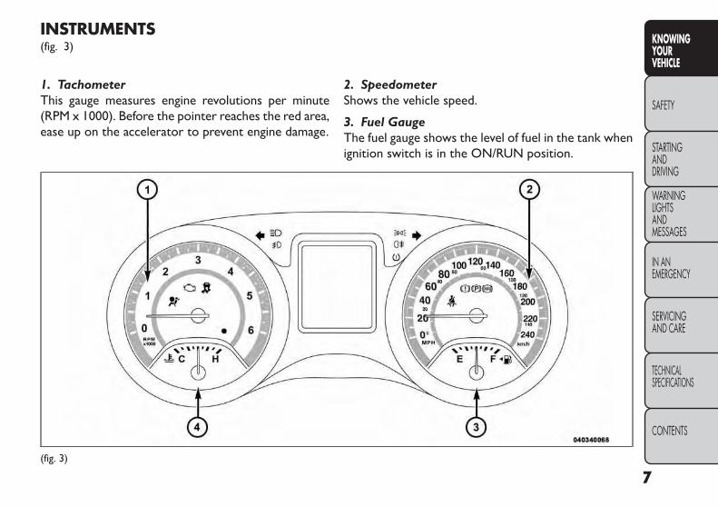
INSTRUMENTS(fig. 3)
1. TachometerThis gauge measures engine revolutions per minute(RPM x 1000). Before the pointer reaches the red area,ease up on the accelerator to prevent engine damage.
2. SpeedometerShows the vehicle speed.
3. Fuel GaugeThe fuel gauge shows the level of fuel in the tank whenignition switch is in the ON/RUN position.
(fig. 3)
7
KNOWINGYOURVEHICLE
SAFETY
STARTINGANDDRIVING
WARNINGLIGHTSANDMESSAGES
IN ANEMERGENCY
SERVICINGAND CARE
TECHNICALSPECIFICATIONS
CONTENTS
4. CoolantTemperature GaugeThe temperature gauge indicates engine coolant tem-perature. Any reading within the normal range indi-cates that the cooling system is operating satisfactorily.The gauge pointer will likely indicate a high tempera-ture when driving in hot weather, up mountain grades,in heavy traffic, or when towing a trailer. If the pointerrises to the “H” mark, safely pull over and stop thevehicle. If the Air Conditioning A/C system is on, turnit off. Also, shift the transmission into NEUTRAL andidle the vehicle. If the needle remains on the “H” mark,turn the engine OFF immediately and call for service.
Do not leave your vehicle unattendedwith the engine running,as you would notbe able to react to the temperature indi-
cator light if the engine overheats.
A WORD ABOUT YOUR KEYSYour vehicle uses a keyless ignition system. This systemconsists of a Key Fob with Remote Keyless Entry (RKE)transmitter and a Keyless Ignition Node (KIN).
Keyless Enter-N-Go Feature™
This vehicle is equipped with the Keyless Enter-N-Go™ feature, refer to “Starting Procedures” in “Start-ing And Driving” for further information.
KEYLESS IGNITION NODE (KIN)This feature allows the driver to operate the ignitionswitch with the push of a button, as long as the RemoteKeyless Entry (RKE) transmitter is in the passengercompartment.
The Keyless Ignition Node (KIN) has four operatingpositions, three of which are labeled and will illuminatewhen in position. The three positions are LOCK/OFF,ACC, and ON/RUN. The fourth position is START.During start RUN will illuminate.
NOTE: In case the ignition switch does not changewith the push of a button, the RKE transmitter (KeyFob) may have a low or dead battery. In this situation aback up method can be used to operate the ignitionswitch. Put the nose side (side opposite of the emer-gency key) of the Key Fob against the ENGINE START/STOP button and push to operate the ignition switch.(fig. 4)
8
KNOWINGYOUR
VEHICLE
SAFETY
STARTINGAND
DRIVING
WARNINGLIGHTS
ANDMESSAGES
IN ANEMERGENCY
SERVICINGAND CARE
TECHNICALSPECIFICATIONS
CONTENTS

Key FobThe Key Fob also contains the Remote Keyless Entry(RKE) transmitter and an emergency key, which storesin the rear of the Key Fob.
The emergency key allows for entry into the vehicleshould the battery in the vehicle or the Key Fob godead. The emergency key is also for locking the glovebox. You can keep the emergency key with you whenvalet parking.
To remove the emergency key, slide the mechanicallatch on the side of the Key Fob sideways with yourthumb and then pull the key out with your other hand.(fig. 5)
NOTE: You can insert the double-sided emergencykey into the lock cylinders with either side up.
Ignition Or Accessory On MessageOpening the driver's door when the ignition is in ACCor ON (engine not running), a chime will sound toremind you to cycle the ignition to OFF. In addition tothe chime, the ignition or accessory on message willdisplay in the cluster.
(fig. 4)Keyless Ignition Node (KIN)
1 — LOCK/OFF2 — ACC (ACCESSORY)3 — ON/RUN (fig. 5)
Emergency Key Removal
9
KNOWINGYOURVEHICLE
SAFETY
STARTINGANDDRIVING
WARNINGLIGHTSANDMESSAGES
IN ANEMERGENCY
SERVICINGAND CARE
TECHNICALSPECIFICATIONS
CONTENTS

NOTE: With the Uconnect® system, the power win-dow switches, radio, power sunroof (for versions/markets, where provided), and power outlets will re-main active for up to 10 minutes after the ignition iscycled to the OFF position. Opening either front doorwill cancel this feature. The time for this feature isprogrammable. Refer to “Uconnect® Settings” in“Knowing Your Vehicle” for further information.
WARNING!• Before exiting a vehicle, always applythe parking brake, shift the transmission
into PARK, and push ignition button to placeignition in OFF position. When leaving the ve-hicle, always lock your vehicle.• Never leave children alone in a vehicle, or withaccess to an unlocked vehicle.• Allowing children to be in a vehicle unattendedis dangerous for a number of reasons.A child orothers could be seriously or fatally injured. Chil-dren should be warned not to touch the parkingbrake, brake pedal or the shift lever.
(Continued)
(Continued)• Do not leave the Key Fob in or near the vehicleor in a location accessible to children,and do notleave the ignition in the ACC or ON/RUN posi-tion.A child could operate power windows, othercontrols, or move the vehicle.• Do not leave children or animals inside parkedvehicles in hot weather. Interior heat build-upmay cause serious injury or death.
An unlocked car is an invitation to thieves.Always remove the Key Fob from vehicle,cycle the ignition OFF and lock all doors
when leaving the vehicle unattended.
10
KNOWINGYOUR
VEHICLE
SAFETY
STARTINGAND
DRIVING
WARNINGLIGHTS
ANDMESSAGES
IN ANEMERGENCY
SERVICINGAND CARE
TECHNICALSPECIFICATIONS
CONTENTS

SENTRY KEY®The Sentry Key® Immobilizer system prevents unau-thorized vehicle operation by disabling the engine. Thesystem does not need to be armed or activated. Op-eration is automatic, regardless of whether the vehicleis locked or unlocked.
The system uses a Key Fob with Remote Keyless Entry(RKE) transmitter, a Keyless Ignition Node (KIN) and aRF receiver to prevent unauthorized vehicle operation.Therefore, only Key Fobs that are programmed to thevehicle can be used to start and operate the vehicle.
After cycling the ignition to the ON/RUN position, theVehicle Security Light will turn on for three seconds fora bulb check. If the light remains on after the bulbcheck, it indicates that there is a problem with theelectronics. In addition, if the light begins to flash afterthe bulb check, it indicates that someone used aninvalid Key Fob to start the engine. Either of theseconditions will result in the engine being shut off aftertwo seconds.
If the Vehicle Security Light turns on during normalvehicle operation (vehicle running for longer than 10seconds), it indicates that there is a fault in the elec-tronics. Should this occur, have the vehicle serviced assoon as possible by an authorized dealer.
All of the Key Fobs provided with your new vehiclehave been programmed to the vehicle electronics.
Replacement Keys
NOTE: Only Key Fobs that are programmed to thevehicle electronics can be used to start and operate thevehicle. Once a Key Fob is programmed to a vehicle, itcannot be programmed to any other vehicle.
• Always remove the Key Fobs from thevehicle and lock all doors when leavingthe vehicle unattended.
• With Keyless Enter-N-Go™, always rememberto place the ignition in the OFF position.
Duplication of Key Fobs may be performed at anauthorized dealer, this procedure consists of program-ming a blank Key Fob to the vehicle electronics. A blankKey Fob is one that has never been programmed.
NOTE: When having the Sentry Key® Immobilizersystem serviced, bring all vehicle Key Fobs with you tothe authorized dealer.
11
KNOWINGYOURVEHICLE
SAFETY
STARTINGANDDRIVING
WARNINGLIGHTSANDMESSAGES
IN ANEMERGENCY
SERVICINGAND CARE
TECHNICALSPECIFICATIONS
CONTENTS

CUSTOMER KEY PROGRAMMINGProgramming Key Fobs or RKE transmitters may beperformed at an authorized dealer.
General InformationThe Sentry Key® Immobilizer system will be used inthe following European countries, which apply Direc-tive 1999/5/EC: Austria, Belgium, Czech Republic,Denmark, Finland, France, Germany, Greece, Hungary,Ireland, Italy, Luxembourg, Netherlands, Norway,Poland, Portugal, Romania, Russian Federation, Slove-nia, Spain, Sweden, Switzerland, Yugoslavia, and UnitedKingdom.
Operation is subject to the following conditions:
• This device may not cause harmful interference.
• This device must accept any interference that may bereceived, including interference that may cause un-desired operation.
REMOTE KEYLESS ENTRY (RKE)The RKE system allows you to lock or unlock thedoors and liftgate from distances up to approximately20 m using a hand-held Key Fob with RKE transmitter.The RKE transmitter does not need to be pointed atthe vehicle to activate the system.
NOTE: Driving at speeds 8 km/h and above disablesthe system from responding to all RKE transmitterbuttons for all RKE transmitters. (fig. 6)
To UnlockThe Doors And LiftgatePress and release the UNLOCK button on the RKEtransmitter once to unlock the driver's door or twicewithin five seconds to unlock all doors and liftgate. The
(fig. 6)Key Fob With RKETransmitter
12
KNOWINGYOUR
VEHICLE
SAFETY
STARTINGAND
DRIVING
WARNINGLIGHTS
ANDMESSAGES
IN ANEMERGENCY
SERVICINGAND CARE
TECHNICALSPECIFICATIONS
CONTENTS

turn signal lights will flash to acknowledge the unlocksignal. The illuminated entry system will also turn on.
If the vehicle is equipped with Passive Entry, refer to“Keyless Enter-N-Go™” under “Knowing Your Ve-hicle” for further information.
Remote Key Unlock, Driver Door/All Doors1st PressThis feature lets you program the system to unlockeither the driver's door or all doors on the first pressof the UNLOCK button on the RKE transmitter.To change the current setting, refer to “Uconnect®Settings” in “Knowing Your Vehicle” for further infor-mation.
Flash Lights With LockThis feature will cause the turn signal lights to flashwhen the doors are locked or unlocked with the RKEtransmitter. This feature can be turned on or turnedoff. To change the current setting, refer to “Uconnect®Settings” in “Knowing Your Vehicle” for further infor-mation.
Turn Headlights On With Remote Key UnlockThis feature activates the headlights for up to 90 sec-onds when the doors are unlocked with the RKEtransmitter. The time for this feature is programmableon vehicles equipped through Uconnect®. To changethe current setting, refer to “Uconnect® Settings” in“Knowing Your Vehicle” for further information.
To LockThe Doors And LiftgatePress and release the LOCK button on the RKE trans-mitter to lock all doors and liftgate. The turn signallights will flash to acknowledge the signal.
If the vehicle is equipped with Passive Entry, refer to“Keyless Enter-N-Go™” under “Knowing Your Ve-hicle” for further information.
Programming AdditionalTransmittersProgramming Key Fobs or RKE transmitters may beperformed at an authorized dealer.
Transmitter Battery ReplacementThe recommended replacement battery is one CR2032battery.
13
KNOWINGYOURVEHICLE
SAFETY
STARTINGANDDRIVING
WARNINGLIGHTSANDMESSAGES
IN ANEMERGENCY
SERVICINGAND CARE
TECHNICALSPECIFICATIONS
CONTENTS
NOTE:
• Perchlorate Material — special handling may apply.Batteries could contain dangerous materials. Pleasedispose of them according to respect for environ-ment and local laws.
• Used batteries are harmful to the environment. Youcan dispose of them either in the correct containersas specified by law or by taking them to a Dealership,which will deal with their disposal.
• Do not touch the battery terminals that are on theback housing or the printed circuit board.
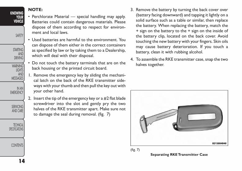
1. Remove the emergency key by sliding the mechani-cal latch on the back of the RKE transmitter side-ways with your thumb and then pull the key out withyour other hand.
2. Insert the tip of the emergency key or a #2 flat bladescrewdriver into the slot and gently pry the twohalves of the RKE transmitter apart. Make sure notto damage the seal during removal. (fig. 7)
3. Remove the battery by turning the back cover over(battery facing downward) and tapping it lightly on asolid surface such as a table or similar, then replacethe battery. When replacing the battery, match the+ sign on the battery to the + sign on the inside ofthe battery clip, located on the back cover. Avoidtouching the new battery with your fingers. Skin oilsmay cause battery deterioration. If you touch abattery, clean it with rubbing alcohol.
4. To assemble the RKE transmitter case, snap the twohalves together.
(fig. 7)Separating RKETransmitter Case
14
KNOWINGYOUR
VEHICLE
SAFETY
STARTINGAND
DRIVING
WARNINGLIGHTS
ANDMESSAGES
IN ANEMERGENCY
SERVICINGAND CARE
TECHNICALSPECIFICATIONS
CONTENTS

GENERAL INFORMATIONTransmitter and receivers operate on a carrier fre-quency of 434 MHz as required by EEC regulations.These devices must be certified to conform to specificregulations in each individual country. Two sets ofregulations are involved: ETS (European Telecommuni-cation Standard) 300–220, which most countries use,and German BZT federal regulation 225Z125, which isbased on ETC 300–220 but has additional unique re-quirements. Other defined requirements are noted inANNEX VI of COMMISSION DIRECTIVE 95/56/EC.Operation is subject to the following conditions:
• This device may not cause harmful interference.
• This device must accept any interference received,including interference that may cause undesired op-eration.
If your RKE transmitter fails to operate from a normaldistance, check for these two conditions:
1. A weak battery in the transmitter. The expected lifeof the battery is a minimum of three years.
2. Closeness to a radio transmitter such as a radiostation tower, airport transmitter, and some mobileor CB radios.
VEHICLE SECURITY ALARMThe Vehicle Security Alarm (VSA) system monitors thevehicle doors, hood, and liftgate for unauthorized en-try and the ignition switch for unauthorized operation.If something triggers the alarm, the system will soundthe horn intermittently, flash the headlights and tail-lights, and flash the Vehicle Security Light in the instru-ment cluster.
Rearming OfThe SystemIf something triggers the alarm, and no action is takento disarm it, the Vehicle Security Alarm will turn off thehorn after 29 seconds, turn off all of the visual signalsafter one minute, and then the Vehicle Security Alarmwill rearm itself.
To ArmThe SystemFollow these steps to arm the Vehicle Security Alarm:
1. Make sure the vehicle ignition system is "OFF".(refer to "Starting Procedures" in "Starting AndDriving" for further information).
2. Perform one of the following methods to lock thevehicle:
• Press LOCK on the interior power door lockswitch with the driver and/or passenger door open.
15
KNOWINGYOURVEHICLE
SAFETY
STARTINGANDDRIVING
WARNINGLIGHTSANDMESSAGES
IN ANEMERGENCY
SERVICINGAND CARE
TECHNICALSPECIFICATIONS
CONTENTS
• Press the LOCK button on the exterior PassiveEntry Door Handle with a valid Key Fob available inthe same exterior zone (refer to "Keyless Enter-N-Go™" in "Knowing Your Vehicle" for further infor-mation).
• Press the LOCK button on the Remote KeylessEntry (RKE) transmitter.
3. If any doors are open, close them.
To DisarmThe SystemThe Vehicle Security Alarm can be disarmed using anyof the following methods:
• Press the UNLOCK button on the Remote KeylessEntry (RKE) transmitter.
• Grasp the Passive Entry Unlock Door Handle with avalid key fob available in the same exterior zone(refer to "Keyless Enter-N-Go™" in "Knowing YourVehicle" for further information).
• Cycle the vehicle ignition system out of the OFFposition by pressing the Keyless Enter-N-Go™Start/Stop button (requires at least one valid Key Fobin the vehicle).
NOTE:
• The driver's door key cylinder and the liftgate buttonon the RKE transmitter cannot arm or disarm theVehicle Security Alarm.
• The Vehicle Security Alarm remains armed duringpower liftgate entry. Pressing the liftgate button willnot disarm the Vehicle Security Alarm. If someoneenters the vehicle through the liftgate and opens anydoor the alarm will sound.
• When the Vehicle Security Alarm is armed, theinterior power door lock switches will not unlockthe doors.
The Vehicle Security Alarm is designed to protect yourvehicle; however, you can create conditions where thesystem will give you a false alarm. If one of the previ-ously described arming sequences has occurred, theVehicle Security Alarm will arm regardless of whetheryou are in the vehicle or not. If you remain in thevehicle and open a door, the alarm will sound. If thisoccurs, disarm the Vehicle Security Alarm.
If the Vehicle Security Alarm is armed and the batterybecomes disconnected, the Vehicle Security Alarm willremain armed when the battery is reconnected; theexterior lights will flash, the horn will sound. If thisoccurs, disarm the Vehicle Security Alarm.
Security System Manual OverrideThe Vehicle Security Alarm will not arm if you lock thedoors using the manual door lock plunger.
16
KNOWINGYOUR
VEHICLE
SAFETY
STARTINGAND
DRIVING
WARNINGLIGHTS
ANDMESSAGES
IN ANEMERGENCY
SERVICINGAND CARE
TECHNICALSPECIFICATIONS
CONTENTS

PREMIUM SECURITY SYSTEM(for versions/markets, whereprovided)The Premium Security system monitors the doors,hood latch, and trunk for unauthorized entry and theignition switch for unauthorized operation. The systemalso includes a dual function intrusion sensor andvehicle tilt sensor. The intrusion sensor monitors thevehicle interior for motion. The vehicle tilt sensormonitors the vehicle for any tilting actions (tow away,tire removal, ferry transport, etc).
In the event that something triggers the security sys-tem, the headlights will turn on, the alarm will soundand the turn signal and side repeater lights will flash for29 seconds, and then the lights will continue to flash foran additional 5 seconds. The system will repeat thissequence for up to 8 security violations in any mode(door ajar, motion, hood ajar, etc.) before having torearm the system. At the end of any particular triggerevent, the lights will continue to flash for 26 seconds.
TO ARMTHE SYSTEMFollow these steps to arm the theft alarm:
1. Make sure the vehicle ignition system is "OFF".(refer to "Starting Procedures" in "Starting AndDriving" for further information).
2. Perform one of the following methods to lock thevehicle:
• Press LOCK on the interior power door lock switchwith the driver and/or passenger door open.
• Press the LOCK button on the exterior PassiveEntry Door Handle with a valid Key Fob available in thesame exterior zone (refer to "Keyless Enter-N-Go™"in "Knowing Your Vehicle" for further information).
• Press the LOCK button on the Remote KeylessEntry (RKE) transmitter.
3. If any doors are open, close them.
NOTE:
• Once the security system is armed, it remains in thatstate until you disarm it by following either of thedisarming procedures described. If a power loss occursafter arming the system, you must disarm the systemafter restoring power to prevent alarm activation.
17
KNOWINGYOURVEHICLE
SAFETY
STARTINGANDDRIVING
WARNINGLIGHTSANDMESSAGES
IN ANEMERGENCY
SERVICINGAND CARE
TECHNICALSPECIFICATIONS
CONTENTS

• The ultrasonic intrusion sensor (motion detector)actively monitors your vehicle every time you armthe security system. If you prefer, you can turn OFFthe ultrasonic intrusion sensor and vehicle tilt sensorwhen arming the security system. To do so, press theLOCK button on the RKE transmitter three timeswithin 5 seconds of arming the system (while theVehicle Security Light is flashing rapidly).
TO DISARMTHE SYSTEMThe Vehicle Security Alarm can be disarmed using anyof the following methods:
• Press the UNLOCK button on the Remote KeylessEntry (RKE) transmitter.
• Grasp the Passive Entry Unlock Door Handle with avalid key fob available in the same exterior zone(refer to "Keyless Enter-N-Go™" in "Knowing YourVehicle" for further information).
• Cycle the vehicle ignition system out of the OFFposition by pressing the Keyless Enter-N-Go™Start/Stop button (requires at least one valid Key Fobin the vehicle).
NOTE:
• The driver's door key cylinder and the trunk buttonon the RKE transmitter cannot arm or disarm theVehicle Security Alarm.
• When the Vehicle Security Alarm is armed, theinterior power door lock switches will not unlockthe doors.
The Vehicle Security Alarm is designed to protect yourvehicle; however, you can create conditions where thesystem will give you a false alarm. If one of the previ-ously described arming sequences has occurred, theVehicle Security Alarm will arm regardless of whetheryou are in the vehicle or not. If you remain in thevehicle and open a door, the alarm will sound. If thisoccurs, disarm the Vehicle Security Alarm.
If the Vehicle Security Alarm is armed and the batterybecomes disconnected, the Vehicle Security Alarm willremain armed when the battery is reconnected; theexterior lights will flash, the horn will sound. If thisoccurs, disarm the Vehicle Security Alarm.
SECURITY SYSTEM MANUAL OVERRIDEThe system will not arm if you lock the doors using themanual door lock plunger.
18
KNOWINGYOUR
VEHICLE
SAFETY
STARTINGAND
DRIVING
WARNINGLIGHTS
ANDMESSAGES
IN ANEMERGENCY
SERVICINGAND CARE
TECHNICALSPECIFICATIONS
CONTENTS

STEERING WHEEL LOCK(for versions/markets, whereprovided)Your vehicle may be equipped with a passive electronicsteering wheel lock. This lock prevents steering thevehicle without the ignition key. If the steering wheel ismoved to one of the lock positions with the key in theoff positions, the steering wheel will lock.
TO MANUALLY LOCKTHE STEERINGWHEELWith the engine running, rotate the steering wheelone-half revolution in either direction (three o’clock ornine o’clock position), turn off the engine and removethe key. Turn the steering wheel slightly in eitherdirection until the lock engages.
TO RELEASETHE STEERING WHEEL LOCKCycle the ignition and start the engine.
NOTE: If you turned the wheel to the right to engagethe lock, you must turn the wheel slightly to the rightto disengage it. If you turned the wheel to the left toengage the lock, turn the wheel slightly to the left todisengage it.
ELECTRONIC VEHICLEINFORMATION CENTER (EVIC)The Electronic Vehicle Information Center (EVIC) fea-tures a driver-interactive display that is located in theinstrument cluster. (fig. 8)
This system allows the driver to select a variety ofuseful information by pressing the switches mountedon the steering wheel. The EVIC consists of the follow-ing:
• Radio Info
• Fuel Economy
• Vehicle Speed
• Trip Info
(fig. 8)ElectronicVehicle Information Center (EVIC)
19
KNOWINGYOURVEHICLE
SAFETY
STARTINGANDDRIVING
WARNINGLIGHTSANDMESSAGES
IN ANEMERGENCY
SERVICINGAND CARE
TECHNICALSPECIFICATIONS
CONTENTS

• Tire Pressure
• Vehicle Information
• Warning Message Displays
• Turn Menu OFF
The system allows the driver to select information bypressing the following buttons mounted on the steer-ing wheel: (fig. 9)
• UP Button
Press and release the UP button to scroll up-ward through the main menus (Fuel Economy,Vehicle Info, Tire PSI, Cruise, Messages, Units)
and sub-menus.
• DOWN Button
Press and release the DOWN button toscroll downward through the main menusand sub-menus.
• SELECT Button
Press and release the SELECT button foraccess to main menus or sub-menus. Pressand hold the SELECT button for two seconds
to reset features.
• BACK Button
Press the BACK button to scroll back to aprevious menu.
ELECTRONICVEHICLE INFORMATIONCENTER (EVIC) DISPLAYSThe EVIC display consists of three sections:
1. The top line where compass direction, odometerline and outside temperature are displayed.
2. The main display area where the menus and pop upmessages are displayed.
3. The reconfigurable telltales section below theodometer line.
(fig. 9)EVIC Steering Wheel Buttons
20
KNOWINGYOUR
VEHICLE
SAFETY
STARTINGAND
DRIVING
WARNINGLIGHTS
ANDMESSAGES
IN ANEMERGENCY
SERVICINGAND CARE
TECHNICALSPECIFICATIONS
CONTENTS

The main display area will normally display the mainmenu or the screens of a selected feature of the mainmenu. The main display area also displays "pop up"messages that consist of approximately 60 possiblewarning or information messages. These pop up mes-sages fall into several categories:
• Five Second Stored MessagesWhen the appropriate conditions occur, this type ofmessage takes control of the main display area for fiveseconds and then returns to the previous screen. Mostof the messages of this type are then stored (as long asthe condition that activated it remains active) and canbe reviewed from the "Messages" main menu item. Aslong as there is a stored message, an "i" will be displayedin the EVIC's compass/outside temp line. Examples ofthis message type are "Right Front Turn Signal LampOut" and "Low Tire Pressure".
• Unstored MessagesThis message type is displayed indefinitely or until thecondition that activated the message is cleared. Ex-amples of this message type are "Turn Signal On" (if aturn signal is left on) and "Lights On" (if driver leavesthe vehicle).
• Unstored Messages Until RUNThis message type is displayed until the ignition is in theRUN state. Example of this message type is "PressBrake Pedal and Push Button to Start".
• Five Second Unstored MessagesWhen the appropriate conditions occur, this type ofmessage takes control of the main display area for fiveseconds and then returns to the previous screen.Examples of this message type are "Memory SystemUnavailable - Not in Park" and "Automatic High BeamsOn".
The Reconfigurable Telltales section is divided into thewhite telltales area on the right, amber telltales in themiddle, and red telltales on the left.
When the appropriate conditions exist, the EVIC dis-plays the following messages:
• Turn Signal On (with a continuous warning chime ifthe vehicle is driven more than 1.6 km with eitherturn signal on)
• Left Front Turn Signal Light Out (with a single chime)
• Left Rear Turn Signal Light Out (with a single chime)
• Right Front Turn Signal Light Out (with a singlechime)
• Right Rear Turn Signal Light Out (with a single chime)
• RKE Battery Low (with a single chime)
• Personal Settings Not Available – Vehicle Not inPARK (for versions/markets, where provided)
21
KNOWINGYOURVEHICLE
SAFETY
STARTINGANDDRIVING
WARNINGLIGHTSANDMESSAGES
IN ANEMERGENCY
SERVICINGAND CARE
TECHNICALSPECIFICATIONS
CONTENTS

• Left/Right Front Door Ajar (one or more doorsopen, with a single chime if speed is above 1.6 km/h)
• Left/Right Rear Door Ajar (one or more doors open,with a single chime if speed is above 1.6 km/h)
• Door(s) Ajar (with a single chime if vehicle is inmotion)
• Liftgate Ajar (with a single chime)
• Low Washer Fluid (with a single chime)
• Ignition or Accessory On
• Vehicle Not in Park (for versions/markets, whereprovided)
• Key Left Vehicle
• Key Not Detected
• Low Tire Pressure (with a single chime). Refer toinformation on “Tire Pressure” and “Tire PressureMonitor” in “Knowing Your Vehicle”.
• Inflate Tire to XXX. Refer to information on "TirePressure" and "Tire Pressure Monitor" in "KnowingYour Vehicle."
• Service TPM System (with a single chime). Refer toinformation on “Tire Pressure Monitor” in “KnowingYour Vehicle”.
• Oil Change Required (with a single chime)
• Check Gascap (refer to “Adding Fuel” in “KnowingYour Vehicle”)
• Oil Change Due (with a single chime)
• Exhaust System — Regeneration Required Now.Under conditions of exclusive short duration andlow speed driving and low speed driving cycles, theengine and exhaust after-treatment system maynever reach the conditions required to remove thetrapped PM. If this occurs the “Exhaust System Re-generation Required Now” message will be displayedon the EVIC. By driving your vehicle at highwayspeeds for as little as 30 minutes, you can remedy thecondition in the particulate filter system by allowingthe trapped PM to be removed to restore the systemto normal operating condition.
• Exhaust Service Required — See Dealer Now. Theengine will be de-rated to prevent permanent dam-age to the after-treatment system. If this conditionoccurs, it is necessary to have your vehicle servicedby your local authorized dealer.
22
KNOWINGYOUR
VEHICLE
SAFETY
STARTINGAND
DRIVING
WARNINGLIGHTS
ANDMESSAGES
IN ANEMERGENCY
SERVICINGAND CARE
TECHNICALSPECIFICATIONS
CONTENTS

EVIC WHITETELLTALE LIGHTSThis area will show reconfigurable white caution tell-tales. These telltales include:
• Shift Lever Status — AutomaticTransmissionOnlyThe shift lever status “P,R,N,D,6,5,4,3,2,1” are displayedindicating the shift lever position. Telltales “6, 5,4,3,2,1”indicate the Autostick™ feature has been engaged andthe gear selected is displayed. For further information onAutostick™, refer to “Starting And Driving.”
• Electronic Speed Control ONThis light will turn on when the electronicspeed control is ON. For further informa-tion, refer to “Electronic Speed Control” in“Knowing Your Vehicle.”
• Electronic Speed Control SETThis light will turn on when the electronicspeed control is SET. For further information,refer to “Electronic Speed Control” in“Knowing Your Vehicle.”
EVIC AMBERTELLTALE LIGHTSThis area will show reconfigurable amber caution tell-tales. These telltales include:
• Low Fuel LightWhen the fuel level reaches approximately11.0 L this light will turn on, and remain on until
fuel is added.
• Loose Gascap Indicator (for versions/markets,where provided)
If the vehicle diagnostic system determinesthat the fuel filler cap is loose, improperlyinstalled, or damaged, a loose gascap indica-tor will display in the telltale display area.
Tighten the fuel filler cap properly and press the SE-LECT button to turn off the message. If the problemcontinues, the message will appear the next time thevehicle is started.
A loose, improperly installed, or damaged fuel filler capmay also turn on the Malfunction Indicator Light (MIL).
• WindshieldWasher Fluid Low IndicatorThis light will turn on to indicate the wind-shield washer fluid is low.
23
KNOWINGYOURVEHICLE
SAFETY
STARTINGANDDRIVING
WARNINGLIGHTSANDMESSAGES
IN ANEMERGENCY
SERVICINGAND CARE
TECHNICALSPECIFICATIONS
CONTENTS
EVIC REDTELLTALE LIGHTSThis area will show reconfigurable red telltales. Thesetelltales include:
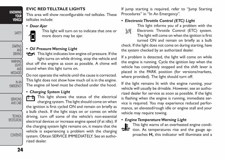
• Door AjarThis light will turn on to indicate that one ormore doors may be ajar.
• Oil PressureWarning LightThis light indicates low engine oil pressure. If thelight turns on while driving, stop the vehicle and
shut off the engine as soon as possible. A chime willsound when this light turns on.
Do not operate the vehicle until the cause is corrected.This light does not show how much oil is in the engine.The engine oil level must be checked under the hood.
• Charging System LightThis light shows the status of the electricalcharging system. The light should come on when
the ignition is first cycled ON and remain on briefly asa bulb check. If the light stays on or comes on whiledriving, turn off some of the vehicle's non-essentialelectrical devices or increase engine speed (if at idle). Ifthe charging system light remains on, it means that thevehicle is experiencing a problem with the chargingsystem. Obtain SERVICE IMMEDIATELY. See an autho-rized dealer.
If jump starting is required, refer to “Jump StartingProcedures” in “In An Emergency”.
• ElectronicThrottle Control (ETC) LightThis light informs you of a problem with theElectronic Throttle Control (ETC) system.The light will come on when the ignition is firstturned ON and remain on briefly as a bulb
check. If the light does not come on during starting, havethe system checked by an authorized dealer.
If a problem is detected, the light will come on whilethe engine is running. Cycle the ignition key when thevehicle has completely stopped and the shift lever isplaced in the PARK position (for versions/markets,where provided). The light should turn off.
If the light remains lit with the engine running, yourvehicle will usually be drivable. However, see an autho-rized dealer for service as soon as possible. If the lightis flashing when the engine is running, immediate ser-vice is required. You may experience reduced perfor-mance, an elevated/rough idle or engine stall and yourvehicle may require towing.
• EngineTemperatureWarning LightThis light warns of an overheated engine condi-tion. As temperatures rise and the gauge ap-proaches H, this indicator will illuminate and a
24
KNOWINGYOUR
VEHICLE
SAFETY
STARTINGAND
DRIVING
WARNINGLIGHTS
ANDMESSAGES
IN ANEMERGENCY
SERVICINGAND CARE
TECHNICALSPECIFICATIONS
CONTENTS
single chime will sound after reaching a set threshold.Further overheating will cause the temperature gaugeto pass H, a continuous chime will occur until theengine is allowed to cool.
If the light turns on while driving, safely pull over andstop the vehicle. If the A/C system is on, turn it off.Also, shift the transmission into NEUTRAL and idle thevehicle. If the temperature reading does not return tonormal, turn the engine off immediately and call forservice.
• TransmissionTemperatureWarning Light(for versions/markets, where provided)
This light indicates that the transmission fluidtemperature is running hot. This may occurwith severe usage, such as trailer towing. Ifthis light turns on, safely pull over and stop
the vehicle. Then, shift the transmission into NEU-TRAL and run the engine at idle or faster until the lightturns off.
Continuous driving with theTransmissionTemperature Warning Light illuminatedwill eventually cause severe transmission
damage or transmission failure.
WARNING!If you continue operating the vehiclewhen the Transmission Temperature
Warning Light is illuminated you could cause thefluid to boil over,come in contact with hot engineor exhaust components and cause a fire.
Gear Shift Indicator (GSI) — forversions/markets, where providedThe Gear Shift Indicator (GSI) system is enabled onvehicles with a manual transmission, or when a vehiclewith an automatic transmission is in manual shift mode.The GSI provides the driver with a visual indicationwithin the EVIC when the recommended gear shift pointhas been reached. This indication notifies the driver thatchanging gear will allow a reduction in fuel consumption.
When the shift up indicator (+) is shown on the display,the GSI is advising the driver to engage a higher gear.(fig. 10) (fig. 11)
When the shift down indicator (-) is shown on thedisplay, the GSI is advising the driver to engage a lowergear. (fig. 12) (fig. 13)
The GSI indicator in the EVIC remains illuminated untilthe driver changes gear, or the driving conditions re-turn to a situation where changing gear is not requiredto improve fuel consumption.
25
KNOWINGYOURVEHICLE
SAFETY
STARTINGANDDRIVING
WARNINGLIGHTSANDMESSAGES
IN ANEMERGENCY
SERVICINGAND CARE
TECHNICALSPECIFICATIONS
CONTENTS

(fig. 10)GSI Shift Up (+) Indicator — AutomaticTransmission
(fig. 11)GSI Shift Up (+) Indicator — ManualTransmission
(fig. 12)GSI Shift Down (-) Indicator — AutomaticTransmission
(fig. 13)GSI Shift Down (-) Indicator — ManualTransmission
26
KNOWINGYOUR
VEHICLE
SAFETY
STARTINGAND
DRIVING
WARNINGLIGHTS
ANDMESSAGES
IN ANEMERGENCY
SERVICINGAND CARE
TECHNICALSPECIFICATIONS
CONTENTS

OIL CHANGE DUEYour vehicle is equipped with an engine oil changeindicator system. The “Oil Change Due” message willflash in the EVIC display for approximately 10 secondsafter a single chime has sounded to indicate the nextscheduled oil change interval. The engine oil changeindicator system is duty cycle based, which means theengine oil change interval may fluctuate dependentupon your personal driving style.
Unless reset, this message will continue to display eachtime you cycle the ignition to the ON/RUN position.To turn off the message temporarily, press and releasethe BACK button. To reset the oil change indicatorsystem please refer to a Fiat Dealership.
FUEL ECONOMYPress and release the UP or DOWN button until “FuelEconomy” displays highlighted in the EVIC and pressthe SELECT button. The following Fuel Economy func-tions will display in the EVIC:
• Average Fuel Economy
• Distance To Empty (DTE)
• Instantaneous Fuel Economy
Average Fuel EconomyShows the average fuel economy since the last reset.When the fuel economy is reset, the display will read
“RESET” or show dashes for two seconds. Then, thehistory information will be erased, and the averagingwill continue from the last fuel average reading beforethe reset. (fig. 14)
DistanceTo Empty (DTE)Shows the estimated distance that can be traveled withthe fuel remaining in the tank. This estimated distanceis determined by a weighted average of the instanta-neous and average fuel economy, according to thecurrent fuel tank level. DTE cannot be reset throughthe SELECT button.
NOTE: Significant changes in driving style or vehicleloading will greatly affect the actual drivable distance ofthe vehicle, regardless of the DTE displayed value.
(fig. 14)Fuel Economy Display
27
KNOWINGYOURVEHICLE
SAFETY
STARTINGANDDRIVING
WARNINGLIGHTSANDMESSAGES
IN ANEMERGENCY
SERVICINGAND CARE
TECHNICALSPECIFICATIONS
CONTENTS
When the DTE value is less than 48 km estimateddriving distance, the DTE display will change to a“LOW FUEL” message. This display will continue untilthe vehicle runs out of fuel. Adding a significant amountof fuel to the vehicle will turn off the “LOW FUEL”message and a new DTE value will display.
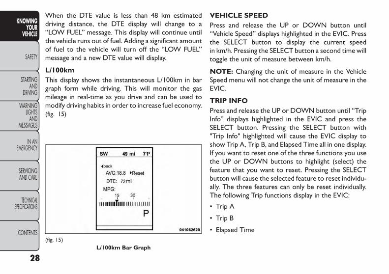
L/100kmThis display shows the instantaneous L/100km in bargraph form while driving. This will monitor the gasmileage in real-time as you drive and can be used tomodify driving habits in order to increase fuel economy.(fig. 15)
VEHICLE SPEEDPress and release the UP or DOWN button until“Vehicle Speed” displays highlighted in the EVIC. Pressthe SELECT button to display the current speedin km/h. Pressing the SELECT button a second time willtoggle the unit of measure between km/h.
NOTE: Changing the unit of measure in the VehicleSpeed menu will not change the unit of measure in theEVIC.
TRIP INFOPress and release the UP or DOWN button until “TripInfo” displays highlighted in the EVIC and press theSELECT button. Pressing the SELECT button with"Trip Info" highlighted will cause the EVIC display toshow Trip A, Trip B, and Elapsed Time all in one display.If you want to reset one of the three functions you usethe UP or DOWN buttons to highlight (select) thefeature that you want to reset. Pressing the SELECTbutton will cause the selected feature to reset individu-ally. The three features can only be reset individually.The following Trip functions display in the EVIC:
• Trip A
• Trip B
• Elapsed Time(fig. 15)
L/100km Bar Graph
28
KNOWINGYOUR
VEHICLE
SAFETY
STARTINGAND
DRIVING
WARNINGLIGHTS
ANDMESSAGES
IN ANEMERGENCY
SERVICINGAND CARE
TECHNICALSPECIFICATIONS
CONTENTS
The Trip Functions mode displays the following infor-mation:
Trip AShows the total distance traveled for Trip A since thelast reset.
Trip BShows the total distance traveled for Trip B since thelast reset.
ElapsedTimeShows the total elapsed time of travel since the lastreset. Elapsed time will increment when the ignition isin the ON/RUN position.
To ResetThe DisplayReset will only occur while a resettable function isbeing displayed. Press and release the SELECT buttononce to clear the resettable function.
TIRE BAR/PSIPress and release the UP or DOWN button until “TireBAR/PSI” displays highlighted in the EVIC. Press theSELECT button to view a graphic of the vehicle with atire pressure value at each corner of the graphic.
VEHICLE INFO (CUSTOMERINFORMATION FEATURES)(for versions/markets, where provided)Press and release the UP or DOWN button until“Vehicle Info” displays in the EVIC and press the SE-LECT button. Press the UP and DOWN button toscroll through the available information displays thatmay be equipped.
• CoolantTempDisplays the actual coolant temperature.
• OilTemperature — for versions/markets, whereprovidedDisplays the actual oil temperature.
• Oil Pressure — for versions/markets, whereprovidedDisplays the actual oil pressure.
• TransTemperatureDisplays the actual transmission sump temperature.
• Engine HoursDisplays the number of hours of engine operation.
29
KNOWINGYOURVEHICLE
SAFETY
STARTINGANDDRIVING
WARNINGLIGHTSANDMESSAGES
IN ANEMERGENCY
SERVICINGAND CARE
TECHNICALSPECIFICATIONS
CONTENTS

MESSAGESIn the Main Menu, press and release the UP or DOWNbutton until “Messages: XX” displays highlighted in theEVIC. If there is more than one message, pressing theSELECT button will display a stored warning message.Press and release the UP and DOWN buttons if thereis more than one message to step through the remain-ing stored messages. If there are no message, pressingthe SELECT button will do nothing.
TURN MENU OFFSelect from Main Menu using the DOWN button.Pressing the SELECT button blanks the menu display.Pressing any one of the four steering wheel buttonsbrings the menu back.
Uconnect® SETTINGSHARD-KEYSHard-Keys are located on the left and right side of theUconnect® 4.3 screen. In addition, there is a Scroll/Enter control knob located on the right side of theClimate Controls in the center of the instrumentpanel. Turn the control knob to scroll through menusand change settings (i.e., 30, 60, 90), press the center ofthe control knob one or more times to select orchange a setting (i.e., ON, OFF).
SOFT-KEYSSoft-Keys are accessible on the Uconnect® touch-screen.
CUSTOMER PROGRAMMABLE FEATURES —Uconnect® 4.3 SETTINGSIn this mode the Uconnect® system allows you toaccess programmable features that may be equippedsuch as Display, Clock, Safety/Assistance, Lights, Doors& Locks, Heated Seats (for versions/markets, whereprovided), Engine Off Operation, Compass Settings,Audio and Phone/Bluetooth settings through hard-keysand soft-keys.
NOTE: Only one touchscreen area may be selected ata time.
30
KNOWINGYOUR
VEHICLE
SAFETY
STARTINGAND
DRIVING
WARNINGLIGHTS
ANDMESSAGES
IN ANEMERGENCY
SERVICINGAND CARE
TECHNICALSPECIFICATIONS
CONTENTS

Press the "Settings" hard-key to access the Settingsscreen, use the Page Up/Down soft-keys to scrollthrough the following settings. Touch the desired set-ting soft key to change the setting using the descriptionshown on the following pages for each setting, (fig. 16)(fig. 17)
Display
• BrightnessPress the Brightness soft-key to change this display.When in this display you may select display brightnesswith the headlights on and the headlights off. Adjust thebrightness with the + and – setting soft-keys or byselecting any point on the scale in between the + and –soft-keys followed by pressing the arrow back soft-key.
• Mode (for versions/markets, where provided)Press the Mode soft-key to change this display. When inthis display you may select one of the auto displaysettings. To change Mode status press and release theDay, Night or Auto soft-key followed by pressing thearrow back soft-key.
• LanguagePress the Language soft-key to change this display.When in this display you may select a different languagefor all display nomenclature, including the trip functionsand the navigation system (for versions/markets, whereprovided). Press the German, French, Spanish, Italian,Dutch or English button to select the language pre-ferred followed by pressing the arrow back soft-key.
(fig. 16)1 — Uconnect® 4.3 Settings Hard-Key
(fig. 17)Uconnect® 4.3 Soft-Keys
31
KNOWINGYOURVEHICLE
SAFETY
STARTINGANDDRIVING
WARNINGLIGHTSANDMESSAGES
IN ANEMERGENCY
SERVICINGAND CARE
TECHNICALSPECIFICATIONS
CONTENTS
Then, as you continue, the information will display inthe selected language.
• UnitsPress the Units soft-key to change this display. When inthis display you may select to have the EVIC, odometer,and navigation system (for versions/markets, whereprovided) changed between US and Metric units ofmeasure. Press US or Metric followed by pressing thearrow back soft-key. Then, as you continue, the infor-mation will display in the selected units of measure.
• Voice Response (for versions/markets, whereprovided)Press the Voice Response soft-key to change this dis-play. When in this display you may change the VoiceResponse Length settings. To change the Voice Re-sponse Length press and release the Brief or Longsoft-key followed by pressing the arrow back soft-key.
• Touch Screen BeepPress the Touch Screen Beep soft-key to change thisdisplay. When in this display you may turn on or shut offthe sound heard when a touch screen button (soft-key)is pressed. To change the Touch Screen Beep settingpress and release the On or Off soft-key followed bypressing the arrow back soft-key.
Clock
• SetTimePress the Set Time soft-key to change this display.When in this display you may select the time displaysettings. To make your selection, press the Set Timesoft-key, adjust the hours and minutes using the up anddown soft-keys, select AM or PM, select 12 hr or 24 hrfollowed by pressing the arrow back soft-key when allselections are complete.
• ShowTime Status (for versions/markets, whereprovided)Press the Show Time Status soft-key to change thisdisplay. When in this display you may turn on or shut offthe digital clock in the status bar. To change the ShowTime Status setting press and release the On or Offsoft-key followed by pressing the arrow back soft-key.
• SyncTime (for versions/markets, where provided)Press the Sync Time soft-key to change this display.When in this display you may automatically have theradio set the time. To change the Sync Time settingpress and release the On or Off soft-key followed bypressing the arrow back soft-key.
32
KNOWINGYOUR
VEHICLE
SAFETY
STARTINGAND
DRIVING
WARNINGLIGHTS
ANDMESSAGES
IN ANEMERGENCY
SERVICINGAND CARE
TECHNICALSPECIFICATIONS
CONTENTS

Safety / Assistance
• Park Assist (for versions/markets, where provided)Press the Park Assist soft-key to change this display.The Rear Park Assist system will scan for objectsbehind the vehicle when the transmission shift lever isin REVERSE and the vehicle speed is less than 11 km/h.The system can be enabled with Sound Only, Soundand Display, or turned OFF. To change the Park Assiststatus press and release the Off, Sound Only or Soundsand Display button followed by pressing the arrow backsoft-key.
• Hill Start Assist (for versions/markets, whereprovided)Press the Hill Start Assist soft-key to change thisdisplay. When this feature is selected, the Hill StartAssist (HSA) system is active. Refer to “ElectronicBrake Control System” in “Starting And Driving” forsystem function and operating information. To makeyour selection, press the Hill Start Assist soft-key,select On or Off followed by pressing the arrow backsoft-key.
Lights
• Headlight Off DelayPress the Headlight Off Delay soft-key to change thisdisplay. When this feature is selected, the driver canchoose to have the headlights remain on for 0, 30, 60,
or 90 seconds when exiting the vehicle. To change theHeadlight Off Delay status press the 0, 30, 60 or 90soft-key followed by pressing the arrow back soft-key.
• Illuminated Approach (for versions/markets,where provided)Press the Illuminated Approach soft-key to change thisdisplay. When this feature is selected, the headlightswill activate and remain on for 0, 30, 60, or 90 secondswhen the doors are unlocked with the RKE transmit-ter. To change the Illuminated Approach status pressthe 0, 30, 60 or 90 soft-key followed by pressing thearrow back soft-key.
• Headlights withWipers (for versions/markets,where provided)Press the Headlights with Wipers soft-key to changethis display. When this feature is selected, and theheadlight switch is in the AUTO position, the head-lights will turn on approximately 10 seconds after thewipers are turned on. The headlights will also turn offwhen the wipers are turned off if they were turned onby this feature. To make your selection, press theHeadlights with Wipers soft-key, select On or Offfollowed by pressing the arrow back soft-key.
33
KNOWINGYOURVEHICLE
SAFETY
STARTINGANDDRIVING
WARNINGLIGHTSANDMESSAGES
IN ANEMERGENCY
SERVICINGAND CARE
TECHNICALSPECIFICATIONS
CONTENTS

• Auto High Beams “SmartBeam™” (for versions/markets, where provided)Press the Auto High Beams soft-key to change thisdisplay. When this feature is selected, the high beamheadlights will deactivate automatically under certainconditions. To make your selection, press the AutoHigh Beams soft-key, select ON or OFF followed bypressing the arrow back soft-key. Refer to “Lights/SmartBeam™ (for versions/markets, where provided)”in “Knowing Your Vehicle” for further information.
• Flash Headlights with Lock (for versions/markets, where provided)Press the Flash Headlights with Lock soft-key to changethis display. When this feature is selected, the front andrear turn signals will flash when the doors are locked orunlocked with the RKE transmitter. To make yourselection, press the Flash Headlights with Lock soft-key, select On or Off followed by pressing the arrowback soft-key.
Doors & Locks
• Auto Unlock on Exit (for versions/markets,where provided)Press the Auto Unlock on Exit soft-key to change thisdisplay. When this feature is selected, all doors willunlock when the vehicle is stopped and the transmis-sion is in the PARK or NEUTRAL position and thedriver's door is opened. To make your selection, press
the Auto Unlock on Exit soft-key, select On or Offfollowed by pressing the arrow back soft-key.
• Flash Lights with Lock (for versions/markets,where provided)Press the Flash Lights with Lock soft-key to change thisdisplay. When this feature is selected, the front andrear turn signals will flash when the doors are locked orunlocked with the RKE transmitter. To make yourselection, press the Flash Lights with Lock soft-key,select On or Off followed by pressing the arrow backsoft-key.
• Remote Door Unlock Order (for versions/markets, where provided)Press the Remote Door Unlock Order soft-key tochange this display. When Unlock Driver Door OnlyOn 1st Press is selected, only the driver's door willunlock on the first press of the RKE transmitter UN-LOCK button. When Driver Door 1st Press is se-lected, you must press the RKE transmitter UNLOCKbutton twice to unlock the passenger's doors. WhenUnlockAll Doors On 1st Press is selected, all of thedoors will unlock on the first press of the RKE trans-mitter UNLOCK button.
NOTE: If the vehicle is equipped with Keyless Enter-N-Go™ (Passive Entry) and the EVIC is programmedto Unlock All Doors 1st Press, all doors will unlock nomatter which Passive Entry equipped door handle is
34
KNOWINGYOUR
VEHICLE
SAFETY
STARTINGAND
DRIVING
WARNINGLIGHTS
ANDMESSAGES
IN ANEMERGENCY
SERVICINGAND CARE
TECHNICALSPECIFICATIONS
CONTENTS

grasped. If Driver Door 1st Press is programmed, onlythe driver’s door will unlock when the driver’s door isgrasped. With Passive Entry, if Driver Door 1st Press isprogrammed touching the handle more than once willonly result in the driver’s door opening. If driver doorfirst is selected, once the driver door is opened, theinterior door lock/unlock switch can be used to unlockall doors (or use RKE transmitter).
• Passive Entry (Keyless Enter-N-Go™)(for versions/markets, where provided)Press the Passive Entry soft-key to change this display.This feature allows you to lock and unlock the vehicle’sdoor(s) without having to press the RKE transmitterlock or unlock buttons. To make your selection, pressthe Passive Entry soft-key, select ON or OFF followedby pressing the arrow back soft-key. Refer to “KeylessEnter-N-Go™” in “Knowing Your Vehicle”.
Heated Seats (for versions/markets, whereprovided)
• Auto Heated Seats (for versions/markets, whereprovided)Press the Auto Heated Seats soft-key to change thisdisplay. When this feature is selected the driver'sheated seat will automatically turn on when tempera-tures are below 44° C. To make your selection, pressthe Auto Heated Seats soft-key, select On or Offfollowed by pressing the arrow back soft-key.
Engine Off Options
• Headlight Off DelayPress the Headlight Off Delay soft-key to change thisdisplay. When this feature is selected, the driver canchoose to have the headlights remain on for 0, 30, 60,or 90 seconds when exiting the vehicle. To change theHeadlight Off Delay status press the 0, 30, 60 or 90soft-key followed by pressing the arrow back soft-key.
• Engine Off Power Delay (for versions/markets,where provided)Press the Engine Off Power Delay soft-key to changethis display. When this feature is selected, the powerwindow switches, radio, Uconnect® phone system (forversions/markets, where provided), DVD video system(for versions/markets, where provided), power sunroof(for versions/markets, where provided), and poweroutlets will remain active for up to 10 minutes after theignition is cycled to OFF. Opening either front vehicledoor will cancel this feature. To change the Engine OffPower Delay status press the 0 seconds, 45 seconds, 5minutes or 10 minutes soft-key followed by pressingthe arrow back soft-key.
35
KNOWINGYOURVEHICLE
SAFETY
STARTINGANDDRIVING
WARNINGLIGHTSANDMESSAGES
IN ANEMERGENCY
SERVICINGAND CARE
TECHNICALSPECIFICATIONS
CONTENTS

Compass Settings
• Variance (for versions/markets, where provided)Press the Variance soft-key to change this display.Compass Variance is the difference between MagneticNorth and Geographic North. To compensate for thedifferences the variance should be set for the zonewhere the vehicle is driven, per the zone map. Onceproperly set, the compass will automatically compen-
sate for the differences, and provide the most accuratecompass heading.
NOTE: Keep magnetic materials away from the topof the instrument panel, such as iPod's, Mobile Phones,Laptops and Radar Detectors. This is where the com-pass module is located, and it can cause interferencewith the compass sensor, and it may give false readings.(fig. 18)
(fig. 18)CompassVariance Map
36
KNOWINGYOUR
VEHICLE
SAFETY
STARTINGAND
DRIVING
WARNINGLIGHTS
ANDMESSAGES
IN ANEMERGENCY
SERVICINGAND CARE
TECHNICALSPECIFICATIONS
CONTENTS

• Calibration (for versions/markets, where provided)Press the Calibration key to change this setting. Thiscompass is self-calibrating, which eliminates the needto manually reset the compass. When the vehicle isnew, the compass may appear erratic and the EVIC willdisplay CAL until the compass is calibrated. You mayalso calibrate the compass by pressing the ON soft-keyand completing one or more 360–degree turns (in anarea free from large metal or metallic objects) until theCAL indicator displayed in the EVIC turns off. Thecompass will now function normally.
NOTE: A good calibration requires a level surfaceand an environment free from large metallic objectssuch as buildings, bridges, underground cables, railroadtracks, etc.
Audio
• Equalizer (for versions/markets, where provided)Press the Equalizer soft-key to change this display.When in this display you may adjust the Bass, Mid andTreble settings. Adjust the settings with the + and –setting soft-keys or by selecting any point on the scalein between the + and – soft-keys followed by pressingthe arrow back soft-key.
NOTE: Bass/mid/treble allow the you to simply slideyour finger up/down to change the setting as well aspress directly on the desired setting.
• Balance / Fade (for versions/markets, whereprovided)Press the Balance / Fade soft-key to change this display.When in this display you may adjust the Balance andFade settings.
• Speed AdjustedVolume (for versions/markets,where provided)Press the Speed Adjusted Volume soft-key to changethis display. Decreases volume relative to vehiclespeed. To change the Speed Adjusted Volume press theOff, 1, 2 or 3 soft-key followed by pressing the arrowback soft-key.
• Surround Sound (for versions/markets, whereprovided)Press the Surround Sound soft-key to change thisdisplay. Provides simulated surround sound mode. Tomake your selection, press the Surround Sound soft-key, select ON or OFF followed by pressing the arrowback soft-key.
Phone / Bluetooth®
• Paired DevicesThis feature shows which phones are paired to thePhone/Bluetooth® system. For further information,refer to the Uconnect® Supplement.
37
KNOWINGYOURVEHICLE
SAFETY
STARTINGANDDRIVING
WARNINGLIGHTSANDMESSAGES
IN ANEMERGENCY
SERVICINGAND CARE
TECHNICALSPECIFICATIONS
CONTENTS

CUSTOMER PROGRAMMABLE FEATURES —Uconnect® 8.4 SETTINGSIn this mode the Uconnect® system allows you toaccess programmable features that may be equippedsuch as Display, Clock, Safety/Assistance, Lights, Doors& Locks, Auto-On Comfort, Engine Off Operation,Compass Settings, Audio and Phone/Bluetooth set-tings.
NOTE: Only one touchscreen area may be selected ata time.
When making a selection, scroll up or down until thepreferred setting is highlighted, then press and releasethe preferred setting until a check-mark appears nextto the setting, showing that setting has been selected.
Display
• Display Mode (for versions/markets, whereprovided)When in this display you may select one of the autodisplay settings. To change Mode status press andrelease the Day, Night or Auto soft-key followed bypressing the arrow back soft-key.
• Display Brightness with Headlights ON(for versions/markets, where provided)When in this display you may select display brightnesswith the headlights on and the headlights off. Adjust thebrightness with the + and – setting soft-keys or by
selecting any point on the scale in between the + and –soft-keys followed by pressing the arrow back soft-key.
• Display Brightness with Headlights OFF(for versions/markets, where provided)When in this display you may select display brightnesswith the headlights on and the headlights off. Adjust thebrightness with the + and – setting soft-keys or byselecting any point on the scale in between the + and –soft-keys followed by pressing the arrow back soft-key.
• Set Language (for versions/markets, whereprovided)When in this display you may select a different languagefor all display nomenclature, including the trip functionsand the navigation system (for versions/markets, whereprovided). Press the German, French, Spanish, Italian,Dutch or English button to select the language pre-ferred followed by pressing the arrow back soft-key.Then, as you continue, the information will display inthe selected language.
• Units (for versions/markets, where provided)When in this display you may select to have the EVIC,odometer, and navigation system (for versions/markets, where provided) changed between US andMetric units of measure. Press US or Metric followedby pressing the arrow back soft-key. Then, as youcontinue, the information will display in the selectedunits of measure.
38
KNOWINGYOUR
VEHICLE
SAFETY
STARTINGAND
DRIVING
WARNINGLIGHTS
ANDMESSAGES
IN ANEMERGENCY
SERVICINGAND CARE
TECHNICALSPECIFICATIONS
CONTENTS
• Voice Response Length (for versions/markets,where provided)When in this display you may change the Voice Re-sponse Length settings. To change the Voice ResponseLength press and release the Brief or Detailed soft-keyfollowed by pressing the arrow back soft-key.
• Touchscreen BeepWhen in this display you may turn on or shut off thesound heard when a touch screen button (soft-key) ispressed. To change the Touch Screen Beep settingpress and release the On or Off soft-key followed bypressing the arrow back soft-key.
• NavigationTurn-By-Turn in Cluster(for versions/markets, where provided)When this feature is selected, the turn-by-turn direc-tions will appear in the display as the vehicle ap-proaches a designated turn within a programmedroute. To make your selection, press the NavigationTurn-By-Turn in Cluster soft-key, select On or Offfollowed by pressing the arrow back soft-key.
Clock
• SyncTime with GPS (for versions/markets,where provided)When in this display you may automatically have theradio set the time. To change the Sync Time setting
press and release the On or Off soft-key followed bypressing the arrow back soft-key.
• SetTime HoursWhen in this display you may select the time displaysettings. To make your selection, press the Set Timesoft-key, adjust the hours using the up and downsoft-keys, followed by pressing the arrow back soft-keywhen all selections are complete.
• SetTime MinutesWhen in this display you may select the time displaysettings. To make your selection, press the Set Timesoft-key, adjust the minutes using the up and downsoft-keys, followed by pressing the arrow back soft-keywhen all selections are complete.
• Time FormatWhen in this display you may select the time displaysettings. To make your selection, press the Set Timesoft-key, select 12 hr or 24 hr followed by pressing thearrow back soft-key when all selections are complete.
• ShowTime in Status Bar (for versions/markets,where provided)When in this display you may turn on or shut off thedigital clock in the status bar. To change the Show TimeStatus setting press and release the On or Off soft-keyfollowed by pressing the arrow back soft-key.
39
KNOWINGYOURVEHICLE
SAFETY
STARTINGANDDRIVING
WARNINGLIGHTSANDMESSAGES
IN ANEMERGENCY
SERVICINGAND CARE
TECHNICALSPECIFICATIONS
CONTENTS

Safety / Assistance
• Park Assist (for versions/markets, where provided)The Rear Park Assist system will scan for objectsbehind the vehicle when the transmission shift lever isin REVERSE and the vehicle speed is less than 11 km/h.The system can be enabled with Sound Only, Soundand Display, or turned OFF. To change the Park Assiststatus press and release the Off, Sound Only or Soundsand Display button followed by pressing the arrow backsoft-key.
• Parkview Backup Camera (for versions/markets,where provided)Your vehicle may be equipped with the ParkView® RearBack Up Camera that allows you to see an on-screenimage of the rear surroundings of your vehicle wheneverthe shift lever is put into REVERSE. The image will bedisplayed on the radio touchscreen display along with acaution note to “check entire surroundings” across thetop of the screen. After five seconds this note willdisappear. The ParkView® camera is located on the rearof the vehicle above the rear License plate. To make yourselection, press the Parkview Backup Camera check boxin the "Safety & Driving Assistance" menu to enable/disable the Parkview Backup Camera.
• Hill Start Assist (for versions/markets, whereprovided)When this feature is selected, the Hill Start Assist(HSA) system is active. Refer to “Electronic BrakeControl System” in “Starting And Driving” for systemfunction and operating information. To make yourselection, press the Hill Start Assist soft-key, select Onor Off followed by pressing the arrow back soft-key.
Lights
• Headlight Off DelayWhen this feature is selected, the driver can choose tohave the headlights remain on for 0, 30, 60, or 90 sec-onds when exiting the vehicle. To change the HeadlightOff Delay status press the 0, 30, 60 or 90 soft-keyfollowed by pressing the arrow back soft-key.
• Headlight Illumination on Approach(for versions/markets, where provided)When this feature is selected, the headlights will acti-vate and remain on for 0, 30, 60, or 90 seconds whenthe doors are unlocked with the RKE transmitter. Tochange the Illuminated Approach status press the 0, 30,60 or 90 soft-key followed by pressing the arrow backsoft-key.
40
KNOWINGYOUR
VEHICLE
SAFETY
STARTINGAND
DRIVING
WARNINGLIGHTS
ANDMESSAGES
IN ANEMERGENCY
SERVICINGAND CARE
TECHNICALSPECIFICATIONS
CONTENTS

• Headlights withWipers (for versions/markets,where provided)When this feature is selected, and the headlight switchis in the AUTO position, the headlights will turn onapproximately 10 seconds after the wipers are turnedon. The headlights will also turn off when the wipersare turned off if they were turned on by this feature. Tomake your selection, press the Headlights with Wiperssoft-key, select On or Off followed by pressing thearrow back soft-key.
• Auto Dim High Beams “SmartBeam™”(for versions/markets, where provided)When this feature is selected, the high beam headlightswill deactivate automatically under certain conditions.To make your selection, press the Auto High Beamssoft-key, select ON or OFF followed by pressing thearrow back soft-key. Refer to “Lights/SmartBeam™(for versions/markets, where provided)” in “KnowingYour Vehicle” for further information.
• Headlight Dipped Beam (Traffic Changeover)(for versions/markets, where provided)Low beam headlights have more control of upwardlight and direct most of their light downward and eitherto the left for right hand drive countries or to the rightfor left hand drive countries to provide safe forwardvisibility without excessive glare.
• Flash HeadlightsWith Lock (for versions/markets, where provided)When this feature is selected, the front and rear turnsignals will flash when the doors are locked or unlockedwith the RKE transmitter. To make your selection, pressthe Flash Headlights with Lock soft-key, select On or Offfollowed by pressing the arrow back soft-key.
Doors & Locks
• Auto Unlock on Exit (for versions/markets,where provided)When this feature is selected, all doors will unlockwhen the vehicle is stopped and the transmission is inthe PARK (for versions/markets, where provided) orNEUTRAL position and the driver's door is opened. Tomake your selection, press the Auto Unlock on Exitsoft-key, select On or Off followed by pressing thearrow back soft-key.
• Flash Headlight with Lock (for versions/markets,where provided)When this feature is selected, the front and rear turnsignals will flash when the doors are locked or unlockedwith the RKE transmitter. To make your selection,press the Flash Lights with Lock soft-key, select On orOff followed by pressing the arrow back soft-key.
41
KNOWINGYOURVEHICLE
SAFETY
STARTINGANDDRIVING
WARNINGLIGHTSANDMESSAGES
IN ANEMERGENCY
SERVICINGAND CARE
TECHNICALSPECIFICATIONS
CONTENTS
• 1st Press of Key Fob Unlocks (for versions/markets, where provided)When Unlock Driver Door Only On 1st Press isselected, only the driver's door will unlock on the firstpress of the RKE transmitter UNLOCK button. WhenDriver Door 1st Press is selected, you must press theRKE transmitter UNLOCK button twice to unlock thepassenger's doors. When Unlock All Doors On 1stPress is selected, all of the doors will unlock on thefirst press of the RKE transmitter UNLOCK button.
NOTE: If the vehicle is equipped with Keyless Enter-N-Go™ (Passive Entry) and the EVIC is programmedto Unlock All Doors 1st Press, all doors will unlock nomatter which Passive Entry equipped door handle isgrasped. If Driver Door 1st Press is programmed, onlythe driver’s door will unlock when the driver’s door isgrasped. With Passive Entry, if Driver Door 1st Press isprogrammed touching the handle more than once willonly result in the driver’s door opening. If driver doorfirst is selected, once the driver door is opened, theinterior door lock/unlock switch can be used to unlockall doors (or use RKE transmitter).
• Passive Entry (for versions/markets, whereprovided)This feature allows you to lock and unlock the vehicle’sdoor(s) without having to press the RKE transmitterlock or unlock buttons. To make your selection, press
the Passive Entry soft-key, select ON or OFF followedby pressing the arrow back soft-key. Refer to “KeylessEnter-N-Go™” in “Knowing Your Vehicle”.
Engine Off Options
• Engine Off Power DelayWhen this feature is selected, the power windowswitches, radio, Uconnect® phone system (for versions/markets, where provided), DVD video system (forversions/markets, where provided), power sunroof (forversions/markets, where provided), and power outletswill remain active for up to 10 minutes after the ignitionis cycled OFF. Opening either front vehicle door willcancel this feature. To change the Engine Off PowerDelay status press the 0 seconds, 45 seconds, 5 minutesor 10 minutes soft-key followed by pressing the arrowback soft-key.
• Headlight Off Delay (for versions/markets,where provided)When this feature is selected, the driver can choose tohave the headlights remain on for 0, 30, 60, or 90 sec-onds when exiting the vehicle. To change the HeadlightOff Delay status press the 0, 30, 60 or 90 soft-keyfollowed by pressing the arrow back soft-key.
42
KNOWINGYOUR
VEHICLE
SAFETY
STARTINGAND
DRIVING
WARNINGLIGHTS
ANDMESSAGES
IN ANEMERGENCY
SERVICINGAND CARE
TECHNICALSPECIFICATIONS
CONTENTS

Compass Settings
• Variance (for versions/markets, where provided)Compass Variance is the difference between MagneticNorth and Geographic North. To compensate for thedifferences the variance should be set for the zonewhere the vehicle is driven, per the zone map. Onceproperly set, the compass will automatically compen-sate for the differences, and provide the most accuratecompass heading.
NOTE: Keep magnetic materials away from the topof the instrument panel, such as iPod's, Mobile Phones,Laptops and Radar Detectors. This is where the com-pass module is located, and it can cause interferencewith the compass sensor, and it may give false readings.(fig. 19)
(fig. 19)CompassVariance Map
43
KNOWINGYOURVEHICLE
SAFETY
STARTINGANDDRIVING
WARNINGLIGHTSANDMESSAGES
IN ANEMERGENCY
SERVICINGAND CARE
TECHNICALSPECIFICATIONS
CONTENTS

• Perform Compass Calibration (for versions/markets, where provided)Press the Calibration key to change this setting. Thiscompass is self-calibrating, which eliminates the needto manually reset the compass. When the vehicle isnew, the compass may appear erratic and the EVIC willdisplay CAL until the compass is calibrated. You mayalso calibrate the compass by pressing the ON soft-keyand completing one or more 360–degree turns (in anarea free from large metal or metallic objects) until theCAL indicator displayed in the EVIC turns off. Thecompass will now function normally.
Audio
• Balance/Fade (for versions/markets, whereprovided)When in this display you may adjust the Balance andFade settings.
• Equalizer (for versions/markets, where provided)When in this display you may adjust the Bass, Mid andTreble settings. Adjust the settings with the + and –setting soft-keys or by selecting any point on the scalein between the + and – soft-keys followed by pressingthe arrow back soft-key.
NOTE: Bass/mid/treble allow the you to simply slideyour finger up/down to change the setting as well aspress directly on the desired setting.
• Speed AdjustedVolume (for versions/markets,where provided)Decreases volume relative to vehicle speed. To changethe Speed Adjusted Volume press the Off, 1, 2 or 3soft-key followed by pressing the arrow back soft-key.
• Music Info Cleanup (for versions/markets, whereprovided)This feature helps organize music files for optimizedmusic navigation. To make your selection, press theMusic Info Cleanup soft-key, select On or Off followedby pressing the arrow back soft-key.
Phone / Bluetooth®
• Paired DevicesThis feature shows which phones are paired to thePhone/Bluetooth® system. For further information,refer to the Uconnect® Supplement.
44
KNOWINGYOUR
VEHICLE
SAFETY
STARTINGAND
DRIVING
WARNINGLIGHTS
ANDMESSAGES
IN ANEMERGENCY
SERVICINGAND CARE
TECHNICALSPECIFICATIONS
CONTENTS

SEATSSeats are a part of the Occupant Restraint System ofthe vehicle.
WARNING!• It is dangerous to ride in a cargo area,inside or outside of a vehicle. In a colli-
sion, people riding in these areas are more likelyto be seriously injured or killed.• Do not allow people to ride in any area of yourvehicle that is not equipped with seats and seatbelts. In a collision, people riding in these areasare more likely to be seriously injured or killed.• Be sure everyone in your vehicle is in a seat andusing a seat belt properly.
DRIVER'S POWER SEAT (for versions/markets, where provided)The power seat switch is on the outboard side of theseat near the floor. Use this switch to move the seat up,down, forward, rearward or to tilt the seat. (fig. 20)
AdjustingThe Seat Forward Or RearwardThe seat can be adjusted both forward and rearward.Push the seat switch forward or rearward, the seat willmove in the direction of the switch. Release the switchwhen the desired position has been reached.
AdjustingThe Seat Up Or DownThe height of the seats can be adjusted up or down. Pullupward or push downward on the seat switch, the seatwill move in the direction of the switch. Release theswitch when the desired position is reached.
TiltingThe Seat Up Or DownThe angle of the seat cushion can be adjusted in fourdirections. Pull upward or push downward on the frontor rear of the seat switch; the front or rear of the seatcushion will move in the direction of the switch. Re-lease the switch when the desired position is reached.
(fig. 20)Power Seat Switch
45
KNOWINGYOURVEHICLE
SAFETY
STARTINGANDDRIVING
WARNINGLIGHTSANDMESSAGES
IN ANEMERGENCY
SERVICINGAND CARE
TECHNICALSPECIFICATIONS
CONTENTS

WARNING!• Adjusting a seat while driving may bedangerous. Moving a seat while driving
could result in loss of control which could cause acollision and serious injury or death.• Seats should be adjusted before fastening theseat belts and while the vehicle is parked.Seriousinjury or death could result from a poorly ad-justed seat belt.• Do not ride with the seatback reclined so thatthe shoulder belt is no longer resting against yourchest. In a collision you could slide under the seatbelt, which could result in serious injury or death.
Do not place any article under a powerseat or impede its ability to move as itmay cause damage to the seat controls.
Seat travel may become limited if movement isstopped by an obstruction in the seat’s path.
POWER LUMBAR (for versions/markets,where provided)The Power Lumbar switch is located on the outboardside of the driver's seat. Push the switch forward toincrease the lumbar support. Push the switch rearwardto decrease the lumbar support. Pushing upward ordownward on the switch will raise or lower the posi-tion of the support. (fig. 21)
HEATED SEATS (for versions/markets, whereprovided)On some models, the front driver and passenger seatsmay be equipped with heaters in both the seat cushionsand seatbacks. The heated seats are operated using theUconnect® System.
(fig. 21)Power Lumbar Switch
46
KNOWINGYOUR
VEHICLE
SAFETY
STARTINGAND
DRIVING
WARNINGLIGHTS
ANDMESSAGES
IN ANEMERGENCY
SERVICINGAND CARE
TECHNICALSPECIFICATIONS
CONTENTS

WARNING!• Persons who are unable to feel pain tothe skin because of advanced age,
chronic illness, diabetes, spinal cord injury, medi-cation, alcohol use, exhaustion or other physicalcondition must exercise care when using the seatheater. It may cause burns even at low tempera-tures, especially if used for long periods of time.• Do not place anything on the seat or seatbackthat insulates against heat, such as a blanket orcushion.This may cause the seat heater to over-heat. Sitting in a seat that has been overheatedcould cause serious burns due to the increasedsurface temperature of the seat.
ForVehicles Equipped With Uconnect® 4.3:Touch the CLIMATE hard-key (located on the left sideof the Uconnect® display) to enter the climate controlscreen.
Touch the “Driver” or “Pass” seat soft-key(located on the Uconnect® display) once toselect HI-level heating. Touch the soft-key a
second time to select LO-level heating. Touch thesoft-key a third time to shut the heating elements OFF.
When the HI-level setting is selected, the heater willprovide a boosted heat level during the first fourminutes of operation. Then, the heat output will dropto the normal HI-level. If the HI-level setting is se-lected, the system will automatically switch to LO-levelafter approximately 60 minutes of continuous opera-tion. At that time, the display will change from HI toLO, indicating the change. The LO-level setting will turnOFF automatically after approximately 45 minutes.
ForVehicles Equipped With Uconnect® 8.4And 8.4 Nav:Touch the “Controls” soft-key located on theUconnect® display. (fig. 22)
(fig. 22)Controls Soft-Key
47
KNOWINGYOURVEHICLE
SAFETY
STARTINGANDDRIVING
WARNINGLIGHTSANDMESSAGES
IN ANEMERGENCY
SERVICINGAND CARE
TECHNICALSPECIFICATIONS
CONTENTS
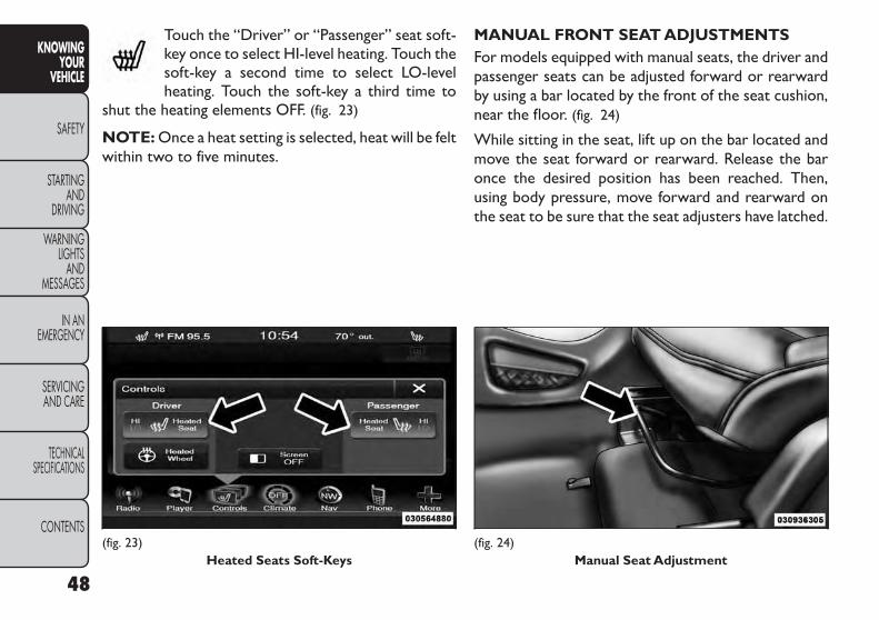
Touch the “Driver” or “Passenger” seat soft-key once to select HI-level heating. Touch thesoft-key a second time to select LO-levelheating. Touch the soft-key a third time to
shut the heating elements OFF. (fig. 23)
NOTE: Once a heat setting is selected, heat will be feltwithin two to five minutes.
MANUAL FRONT SEAT ADJUSTMENTSFor models equipped with manual seats, the driver andpassenger seats can be adjusted forward or rearwardby using a bar located by the front of the seat cushion,near the floor. (fig. 24)
While sitting in the seat, lift up on the bar located andmove the seat forward or rearward. Release the baronce the desired position has been reached. Then,using body pressure, move forward and rearward onthe seat to be sure that the seat adjusters have latched.
(fig. 23)Heated Seats Soft-Keys
(fig. 24)Manual Seat Adjustment
48
KNOWINGYOUR
VEHICLE
SAFETY
STARTINGAND
DRIVING
WARNINGLIGHTS
ANDMESSAGES
IN ANEMERGENCY
SERVICINGAND CARE
TECHNICALSPECIFICATIONS
CONTENTS

WARNING!• Adjusting a seat while driving may bedangerous. Moving a seat while driving
could result in loss of control which could cause acollision and serious injury or death.• Seats should be adjusted before fastening theseat belts and while the vehicle is parked.Seriousinjury or death could result from a poorly ad-justed seat belt.
RECLINER ADJUSTMENTThe recline lever is located on the outboard side of theseat. To recline the seat, lean forward slightly, lift thelever, lean back to the desired position and release thelever. To return the seatback to its normal uprightposition, lean forward and lift the lever. Release the leveronce the seatback is in the upright position. (fig. 25)
WARNING!• Adjusting a seat while the vehicle ismoving is dangerous.The sudden move-
ment of the seat could cause you to lose control.The seat belt might not be adjusted properly andyou could be injured. Adjust the seat only whilethe vehicle is parked.• Do not ride with the seatback reclined so thatthe shoulder belt is no longer resting against yourchest. In a collision you could slide under the seatbelt and be seriously or even fatally injured. Usethe recliner only when the vehicle is parked.
(fig. 25)Seatback Release
49
KNOWINGYOURVEHICLE
SAFETY
STARTINGANDDRIVING
WARNINGLIGHTSANDMESSAGES
IN ANEMERGENCY
SERVICINGAND CARE
TECHNICALSPECIFICATIONS
CONTENTS

DRIVER'S SEAT HEIGHT ADJUSTMENTThe seat height control lever is located on the out-board side of the seat. Raise the lever to raise the seat.Lower the lever to lower the seat. The total seat travelis approximately 55 mm. (fig. 26)
FOLD-FLAT FRONT PASSENGER SEAT(for versions/markets, where provided)This feature allows for extended cargo space. Whenthe seat is folded flat, it is an extension of the load floorsurface (allowing long cargo to fit from the rear hatchup to the instrument panel). The fold-flat seatback alsohas a hardback surface that you can use as a worksurface when the seat is folded flat and the vehicle isnot in motion. (fig. 27)
Pull upward on the recline lever to fold or unfold theseat.
WARNING!Adjusting a seat while the vehicle is mov-ing is dangerous.The sudden movement
of the seat could cause you to lose control.Adjustany seat only while the vehicle is parked.
HEAD RESTRAINTSHead restraints are designed to reduce the risk ofinjury by restricting head movement in the event of arear impact. Head restraints should be adjusted so thatthe top of the head restraint is located above the top ofyour ear.
(fig. 26)Seat Height Adjustment Lever
(fig. 27)Fold-Flat Seat
50
KNOWINGYOUR
VEHICLE
SAFETY
STARTINGAND
DRIVING
WARNINGLIGHTS
ANDMESSAGES
IN ANEMERGENCY
SERVICINGAND CARE
TECHNICALSPECIFICATIONS
CONTENTS

WARNING!The head restraints for all occupantsmust be properly adjusted prior to oper-
ating the vehicle or occupying a seat. Head re-straints should never be adjusted while the ve-hicle is in motion.Driving a vehicle with the headrestraints improperly adjusted or removed couldcause serious injury or death in the event of acollision.
Active Head Restraints (AHR) — Front SeatsActive Head Restraints are passive, deployable compo-nents, and vehicles with this equipment can not bereadily identified by any markings, only through visualinspection of the head restraint. The head restraint willbe split in two halves, with the front half being softfoam and trim, the back half being decorative plastic.
When AHRs deploy during a rear impact, the front halfof the head restraint extends forward to minimize thegap between the back of the occupant’s head and theAHR. This system is designed to help prevent or reducethe extent of injuries to the driver and front passenger incertain types of rear impacts. Refer to “Occupant Re-straints” in “Safety” for further information.
To raise the head restraint, pull upward on the headrestraint. To lower the head restraint, press the pushbutton, located at the base of the head restraint, andpush downward on the head restraint. (fig. 28)
(fig. 28)Push Button
51
KNOWINGYOURVEHICLE
SAFETY
STARTINGANDDRIVING
WARNINGLIGHTSANDMESSAGES
IN ANEMERGENCY
SERVICINGAND CARE
TECHNICALSPECIFICATIONS
CONTENTS

For comfort, the Active Head Restraints can be tiltedforward and backward. To tilt the head restraint closerto the back of your head, pull forward on the bottom ofthe head restraint. Push rearward on the bottom of thehead restraint to move the head restraint away fromyour head. (fig. 29) (fig. 30)
NOTE:
• The head restraints should only be removed byqualified technicians, for service purposes only. Ifeither of the head restraints require removal, seeyour authorized dealer.
• In the event of deployment of an Active Head Re-straint, refer to “Occupant Restraints/SupplementalActive Head Restraints (AHR)/Resetting ActiveHead Restraints (AHR)” in “Safety” for further infor-mation.
(fig. 29)Active Head Restraint (Normal Position)
(fig. 30)Active Head Restraint (Tilted)
52
KNOWINGYOUR
VEHICLE
SAFETY
STARTINGAND
DRIVING
WARNINGLIGHTS
ANDMESSAGES
IN ANEMERGENCY
SERVICINGAND CARE
TECHNICALSPECIFICATIONS
CONTENTS

WARNING!• Do not place items over the top of theActive Head Restraint, such as coats,
seat covers or portable DVD players.These itemsmay interfere with the operation of the ActiveHead Restraint in the event of a collision andcould result in serious injury or death.• Active Head Restraints may be deployed if theyare struck by an object such as a hand, foot orloose cargo. To avoid accidental deployment ofthe Active Head Restraint ensure that all cargo issecured, as loose cargo could contact the ActiveHead Restraint during sudden stops. Failure tofollow this warning could cause personal injury ifthe Active Head Restraint is deployed.
Head Restraints — Second Row SeatsThe rear seats are equipped with adjustable head re-straints. To raise the head restraint, pull upward on thehead restraint. To lower the head restraint, press theadjustment button, located on the base of the headrestraint, and push downward on the head restraint.(fig. 31)
NOTE:
• The head restraints should only be removed by qualifiedtechnicians, for service purposes only. If any of the headrestraints require removal, see your authorized dealer.
• For proper routing of a Child Seat Tether, refer to“Occupant Restraints” in “Safety”.
WARNING!Driving a vehicle with the head restraintsremoved or improperly adjusted could
cause serious injury or death in the event of acollision. The head restraints should be checkedprior to operating the vehicle and never adjustedwhile the vehicle is in motion.
(Continued)
(fig. 31)Adjustment Button
53
KNOWINGYOURVEHICLE
SAFETY
STARTINGANDDRIVING
WARNINGLIGHTSANDMESSAGES
IN ANEMERGENCY
SERVICINGAND CARE
TECHNICALSPECIFICATIONS
CONTENTS

THIRD ROW PASSENGER SEATS(Seven Passenger Models)These head restraints are non-adjustable and non-removable. However, you can fold them forward whenthey are not in use by passengers.
WARNING!Do not allow a passenger to sit in a thirdrow seat without having the head re-
straint unfolded and locked in place. Failure tofollow this warning may result in personal injuryto the passenger in the event of a collision.
60/40 SPLIT SECOND-ROW PASSENGERSEATSTo provide additional storage area, each second-rowpassenger seat can be folded flat. This allows for ex-tended cargo space and still maintains some seatingroom if needed.
NOTE: Prior to folding the second-row passengerseat, make sure the front seatback is not in a reclinedposition. This will allow the second-row seat to foldeasily.
WARNING!• It is extremely dangerous to ride in acargo area, inside or outside of a vehicle.
In a collision, people riding in these areas aremore likely to be seriously injured or killed.• Do not allow people to ride in any area of yourvehicle that is not equipped with seats and seatbelts.• Be sure everyone in your vehicle is in a seat andusing a seat belt properly.• On seven passenger models, do not allow apassenger to sit in a third row seat with thesecond row seatback(s) folded flat. In a collision,the passenger could slide underneath the seatbelt and be seriously or even fatally injured.
To FoldThe Seat
1. Locate the control lever on the lower outboard sideof the seat. (fig. 32)
2. Place one hand on the seatback and apply a gentlepressure.
54
KNOWINGYOUR
VEHICLE
SAFETY
STARTINGAND
DRIVING
WARNINGLIGHTS
ANDMESSAGES
IN ANEMERGENCY
SERVICINGAND CARE
TECHNICALSPECIFICATIONS
CONTENTS

3. Lift the control lever with the other hand, allow theseatback to move forward slightly, and then releasethe lever.
WARNING!To prevent personal injury or damage toobjects, keep your head, arms, and ob-
jects out of the folding path of the seatback.
4. Gently guide the seatback into the folded position.
To UnfoldThe SeatRaise the seatback and lock it in place.
WARNING!Be certain that the seatback is lockedsecurely into position. Otherwise, the
seat will not provide the proper stability for childseats and/or passengers. An improperly latchedseat could cause serious injury.
Forward And Rearward AdjustmentThe control lever is on the outboard side of the seat.Lift the lever to move the seat forward or rearward.Release the lever once the seat is in the desiredposition. Then, using body pressure, move forward andrearward on the seat to be sure that the seat adjustershave latched. (fig. 33)
(fig. 32)Seatback Release
(fig. 33)Manual Seat Adjustment
55
KNOWINGYOURVEHICLE
SAFETY
STARTINGANDDRIVING
WARNINGLIGHTSANDMESSAGES
IN ANEMERGENCY
SERVICINGAND CARE
TECHNICALSPECIFICATIONS
CONTENTS
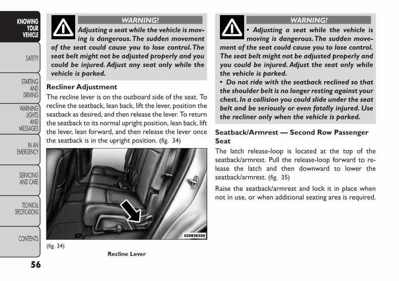
WARNING!Adjusting a seat while the vehicle is mov-ing is dangerous.The sudden movement
of the seat could cause you to lose control.Theseat belt might not be adjusted properly and youcould be injured. Adjust any seat only while thevehicle is parked.
Recliner AdjustmentThe recline lever is on the outboard side of the seat. Torecline the seatback, lean back, lift the lever, position theseatback as desired, and then release the lever. To returnthe seatback to its normal upright position, lean back, liftthe lever, lean forward, and then release the lever oncethe seatback is in the upright position. (fig. 34)
WARNING!• Adjusting a seat while the vehicle ismoving is dangerous.The sudden move-
ment of the seat could cause you to lose control.The seat belt might not be adjusted properly andyou could be injured. Adjust the seat only whilethe vehicle is parked.• Do not ride with the seatback reclined so thatthe shoulder belt is no longer resting against yourchest. In a collision you could slide under the seatbelt and be seriously or even fatally injured. Usethe recliner only when the vehicle is parked.
Seatback/Armrest — Second Row PassengerSeatThe latch release-loop is located at the top of theseatback/armrest. Pull the release-loop forward to re-lease the latch and then downward to lower theseatback/armrest. (fig. 35)
Raise the seatback/armrest and lock it in place whennot in use, or when additional seating area is required.
(fig. 34)Recline Lever
56
KNOWINGYOUR
VEHICLE
SAFETY
STARTINGAND
DRIVING
WARNINGLIGHTS
ANDMESSAGES
IN ANEMERGENCY
SERVICINGAND CARE
TECHNICALSPECIFICATIONS
CONTENTS

WARNING!Keep the latch clean and free of objectsand be certain that the seatback/
armrest is locked securely into position. Other-wise,the seat will not provide the proper stabilityfor child seats and/or passengers.An improperlylatched seat could cause serious injury.
StadiumTip 'n Slide™ (Easy Entry/Exit Seat) —Seven Passenger ModelsThis feature allows passengers to easily enter or exitthe third-row passenger seats from either side of thevehicle.
To MoveThe Second-Row Passenger SeatForward
NOTE: Raise the seatback/armrest before moving theseat to allow for full seat travel.
Move the control lever on the upper outboard side ofthe seatback forward. Then, in one fluid motion, theseat cushion flips upward and the seat moves forwardon its tracks. (fig. 36) (fig. 37)
NOTE: A hand-grip is molded into the front of eachquarter trim panel near the door opening to assistentry and exit from the third-row passenger seats.
(fig. 35)Seatback/Armrest
(fig. 36)Tip 'n Slide™ Control Lever
57
KNOWINGYOURVEHICLE
SAFETY
STARTINGANDDRIVING
WARNINGLIGHTSANDMESSAGES
IN ANEMERGENCY
SERVICINGAND CARE
TECHNICALSPECIFICATIONS
CONTENTS

WARNING!Do not drive the vehicle with the seat inthis position, as it is only intended for
entering and exiting the third row seats. Failure tofollow this warning may result in personal injury.
To Unfold And MoveThe Second-RowPassenger Seat Rearward
Move the seatback rearward until it locks in place andthen continue sliding the seat rearward on its tracksuntil it locks in place.
Push the seat cushion downward to lock it in place.
Adjust the seat track position as desired. Using bodypressure, move forward and rearward on the seat to besure that the seat adjusters have latched.
WARNING!Be certain that the seatback and seatare locked securely into position. Other-
wise,the seat will not provide the proper stabilityfor child seats and/or passengers.An improperlylatched seat could cause serious injury.
50/50 SPLITTHIRD-ROW PASSENGERSEATS WITH FOLD-FLAT FEATURE(Seven Passenger Models)To provide additional storage area, each third-rowpassenger seatback can be folded flat. This allows forextended cargo space and still maintains some rearseating room if needed.
NOTE: Prior to folding the third-row passenger seat-back, make sure the second-row passenger seatback isnot in a reclined position. This will allow the seatbackto fold easily.
(fig. 37)Tip 'n Slide™ Seat
58
KNOWINGYOUR
VEHICLE
SAFETY
STARTINGAND
DRIVING
WARNINGLIGHTS
ANDMESSAGES
IN ANEMERGENCY
SERVICINGAND CARE
TECHNICALSPECIFICATIONS
CONTENTS

To FoldThe SeatbackPull the latch release-loop located at the top of theseatback upward, push the seatback forward slightly,and release the release-loop. Then, continue to pushthe seatback forward. The head restraints will foldautomatically as the seatback moves forward. (fig. 38)
To UnfoldThe SeatbackGrasp the assist strap loop on the seatback and pull ittoward you to raise the seatback. Continue to raise theseatback until it locks in place. Raise the head restraintto lock it in place. (fig. 39)
The seatback can also be locked in the reclined posi-tion. To do so, pull the latch release-loop located at thetop of the seatback upward, allow the seatback torecline, and release the release-loop.
(fig. 38)Seatback Release
(fig. 39)Assist Strap
59
KNOWINGYOURVEHICLE
SAFETY
STARTINGANDDRIVING
WARNINGLIGHTSANDMESSAGES
IN ANEMERGENCY
SERVICINGAND CARE
TECHNICALSPECIFICATIONS
CONTENTS

WARNING!• Be certain that the seatback is lockedsecurely into position. Otherwise, the
seat will not provide the proper stability forpassengers. An improperly latched seat couldcause serious injury.• Do not allow a passenger to sit in a third rowseat without having the head restraint unfoldedand locked in place.Failure to follow this warningmay result in personal injury to the passenger inthe event of a collision.• Do not allow a passenger to sit in a third rowseat with the second row seatback(s) folded flat.In a collision, the passenger could slide under-neath the seat belt and be seriously or evenfatally injured.
TILT/TELESCOPING STEERINGCOLUMNThis feature allows you to tilt the steering columnupward or downward. It also allows you to lengthen orshorten the steering column. The tilt/telescoping con-trol handle is located below the steering wheel at theend of the steering column. (fig. 40)
To unlock the steering column, push the control handledownward. To tilt the steering column, move the steer-ing wheel upward or downward as desired. To lengthenor shorten the steering column, pull the steering wheeloutward or push it inward as desired. To lock thesteering column in position, pull the control handleupward until fully engaged.
(fig. 40)Tilt/Telescoping Steering Control Handle
60
KNOWINGYOUR
VEHICLE
SAFETY
STARTINGAND
DRIVING
WARNINGLIGHTS
ANDMESSAGES
IN ANEMERGENCY
SERVICINGAND CARE
TECHNICALSPECIFICATIONS
CONTENTS
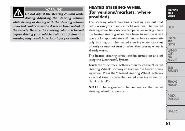
WARNING!Do not adjust the steering column whiledriving. Adjusting the steering column
while driving or driving with the steering columnunlocked could cause the driver to lose control ofthe vehicle.Be sure the steering column is lockedbefore driving your vehicle. Failure to follow thiswarning may result in serious injury or death.
HEATED STEERING WHEEL(for versions/markets, whereprovided)The steering wheel contains a heating element thathelps warm your hands in cold weather. The heatedsteering wheel has only one temperature setting. Oncethe heated steering wheel has been turned on it willoperate for approximately 80 minutes before automati-cally shutting off. The heated steering wheel can shutoff early or may not turn on when the steering wheel isalready warm.
The heated steering wheel can be turned on and offusing the Uconnect® System.
Touch the “Controls” soft-key then touch the “HeatedSteering Wheel” soft-key to turn on the heated steer-ing wheel. Press the “Heated Steering Wheel” soft-keya second time to turn the heated steering wheel off.(fig. 41) (fig. 42)
NOTE: The engine must be running for the heatedsteering wheel to operate.
61
KNOWINGYOURVEHICLE
SAFETY
STARTINGANDDRIVING
WARNINGLIGHTSANDMESSAGES
IN ANEMERGENCY
SERVICINGAND CARE
TECHNICALSPECIFICATIONS
CONTENTS

WARNING!• Persons who are unable to feel pain tothe skin because of advanced age,
chronic illness, diabetes, spinal cord injury, medi-cation, alcohol use, exhaustion or other physicalcondition must exercise care when using the seatheater. It may cause burns even at low tempera-tures, especially if used for long periods of time.• Do not place anything on the seat or seatbackthat insulates against heat, such as a blanket orcushion.This may cause the seat heater to over-heat. Sitting in a seat that has been overheatedcould cause serious burns due to the increasedsurface temperature of the seat.(fig. 41)
Controls Soft-Key
(fig. 42)Heated Steering Wheel Soft-Key
62
KNOWINGYOUR
VEHICLE
SAFETY
STARTINGAND
DRIVING
WARNINGLIGHTS
ANDMESSAGES
IN ANEMERGENCY
SERVICINGAND CARE
TECHNICALSPECIFICATIONS
CONTENTS

MIRRORSINSIDE DAY/NIGHT MIRRORA two-point pivot system allows for horizontal andvertical adjustment of the mirror. Adjust the mirror tocenter on the view through the rear window.
Headlight glare can be reduced by moving the smallcontrol lever under the mirror to the night position(lever flipped toward the rear of vehicle). The mirrorshould be adjusted while set in the day position (to-ward the windshield). (fig. 43)
AUTOMATIC DIMMING MIRROR(for versions/markets, where provided)This mirror automatically adjusts for headlight glarefrom vehicles behind you. This feature will be defaultedon, and only be disabled when the vehicle is moving inreverse. (fig. 44)
To avoid damage to the mirror duringcleaning, never spray any cleaning solu-tion directly onto the mirror. Apply the
solution onto a clean cloth and wipe the mirrorclean.
(fig. 43)Adjusting Rearview Mirror
(fig. 44)Automatic Dimming Mirror
63
KNOWINGYOURVEHICLE
SAFETY
STARTINGANDDRIVING
WARNINGLIGHTSANDMESSAGES
IN ANEMERGENCY
SERVICINGAND CARE
TECHNICALSPECIFICATIONS
CONTENTS

OUTSIDE MIRRORSTo receive maximum benefit, adjust the outside mir-ror(s) to center on the adjacent lane of traffic and aslight overlap of the view obtained from the insidemirror.
NOTE: The passenger side convex outside mirror willgive a much wider view to the rear, and especially of thelane next to your vehicle.
WARNING!Vehicles and other objects seen in thepassenger side convex mirror will look
smaller and farther away than they really are.Relying too much on your passenger side convexmirror could cause you to collide with anothervehicle or other object. Use your inside mirrorwhen judging the size or distance of a vehicleseen in the passenger side convex mirror. Failureto follow this warning may result in serious injuryor death.
POWER MIRRORSThe power mirror switch is located on the driver'sdoor trim panel. (fig. 45)
Models Without Express Window Feature
Press the mirror select button marked L (left) orR (right) and then press one of the four arrow buttonsto move the mirror in the direction the arrow ispointing.
Models With Express Window Feature
Press and release the mirror select button markedL (left) or R (right) and then press one of the four arrowbuttons to move the mirror in the direction the arrow ispointing. The selection times out after 30 seconds ofinactivity in order to guard against accidentally changinga mirror position following an adjustment.
NOTE: A light in the selected button will illuminateindicating the mirror is activated and can be adjusted.
(fig. 45)Power Mirror Switches
64
KNOWINGYOUR
VEHICLE
SAFETY
STARTINGAND
DRIVING
WARNINGLIGHTS
ANDMESSAGES
IN ANEMERGENCY
SERVICINGAND CARE
TECHNICALSPECIFICATIONS
CONTENTS

POWER FOLDING MIRRORS (forversions/markets, where provided)The switch for the power folding mirrors is locatedbetween the power mirror switches L (left) and R (right).Press the switch once and the mirrors will fold in,pressing the switch a second time will return the mirrorsto the normal driving position.
NOTE: If the vehicle speed is greater than 16 km/h thefolding feature will be disabled.
If the mirrors are in the folded position, and vehiclespeed is equal or greater than 8 km/h, they will auto-matically unfold.
MANUAL FOLDING MIRRORSSome models have exterior mirrors that are hinged.The hinge allows the mirror to pivot forward andrearward to resist damage. The hinge has three detentpositions: forward, rearward and normal.
HEATED MIRRORS (for versions/markets,where provided)
These mirrors are heated to melt frost or ice.This feature is activated whenever you turn on
the rear window defroster. Refer to “Rear WindowFeatures” for further information.
ILLUMINATEDVANITY MIRRORS(for versions/markets, where provided)An illuminated vanity mirror is on each sun visor. To usethe mirror, rotate the sun visor downward and swing themirror cover upward. The light will turn on automatically.Closing the mirror cover will turn off the light. (fig. 46)
SunVisor “Slide-On Rod” Feature(for versions/markets, where provided)This feature allows for additional flexibility in position-ing the visor to block out the sun.1. Fold down the sun visor.2. Unclip the visor from the center clip.3. Pull the sun visor toward the inside rearview mirror
to extend it.
(fig. 46)IlluminatedVanity Mirror
65
KNOWINGYOURVEHICLE
SAFETY
STARTINGANDDRIVING
WARNINGLIGHTSANDMESSAGES
IN ANEMERGENCY
SERVICINGAND CARE
TECHNICALSPECIFICATIONS
CONTENTS

CLIMATE CONTROLSThe air conditioning and heating system is designed tomake you comfortable in all types of weather. Thissystem can be operated through either the instrumentpanel or through the Uconnect® system display.
When the Uconnect® system is in different modes(Radio, Player, Settings, More, etc.) the driver andpassenger temperature settings will be indicated at thetop of the display.
Manual Climate Controls WithTouchscreen(for versions/markets, where provided)
Hard-KeysHard-keys are located on the left and right side of theUconnect® 4.3 screen in the center of the instrumentpanel. There are also hard-keys located below theUconnect® touch screen. (fig. 47) (fig. 48)
Soft-KeysSoft-keys are accessible on the Uconnect® systemscreen. (fig. 49) (fig. 50)
(fig. 47)
(fig. 48)ManualTemperature Controls — Hard-Keys
66
KNOWINGYOUR
VEHICLE
SAFETY
STARTINGAND
DRIVING
WARNINGLIGHTS
ANDMESSAGES
IN ANEMERGENCY
SERVICINGAND CARE
TECHNICALSPECIFICATIONS
CONTENTS

Button Descriptions(AppliesTo Both Hard-keys And Soft-keys)
1. MAX A/C ButtonPress and release to change the current setting, theindicator illuminates when MAX A/C is ON. Perform-ing this function again will cause the MAX A/C opera-tion to switch into manual mode and the MAX A/Cindicator will turn off.
2. A/C ButtonPress and release to change the current setting, theindicator illuminates when A/C is ON. Performing thisfunction again will cause the A/C operation to switchinto manual mode and the A/C indicator will turn off.
3. Recirculation ButtonPress and release to change the current setting, theindicator illuminates when ON.
4. Front Defrost ButtonPress and release to change the current airflow settingto Defrost mode. The indicator illuminates when thisfeature is ON. Air comes from the windshield and sidewindow demist outlets. When the defrost button isselected, the blower level will increase. Use Defrostmode with maximum temperature settings for bestwindshield and side window defrosting and defogging.Performing this function will cause the ATC to switchinto manual mode. If the front defrost mode is turnedoff the climate system will return the previous setting.
(fig. 49)Uconnect® 4.3 Manual 3 — ZoneTemperature
Controls — Soft-keys
(fig. 50)Uconnect® 8.4 Manual 3 — ZoneTemperature
Controls — Soft-keys
67
KNOWINGYOURVEHICLE
SAFETY
STARTINGANDDRIVING
WARNINGLIGHTSANDMESSAGES
IN ANEMERGENCY
SERVICINGAND CARE
TECHNICALSPECIFICATIONS
CONTENTS

5. Rear Defrost ButtonPress and release this button to turn on the rearwindow defroster and the heated outside mirrors (forversions/markets, where provided). An indicator willilluminate when the rear window defroster is on. Therear window defroster automatically turns off after10 minutes.
Failure to follow these cautions cancause damage to the heating elements:• Use care when washing the inside of
the rear window. Do not use abrasive windowcleaners on the interior surface of the window.Use a soft cloth and a mild washing solution,wiping parallel to the heating elements. Labelscan be peeled off after soaking with warm water.• Do not use scrapers,sharp instruments,or abra-sive window cleaners on the interior surface ofthe window.• Keep all objects a safe distance from the win-dow.
6. Rear Climate Button (for versions/markets,where provided)Press and release this button to turn on the rearclimate controls. The indicator will illuminate when therear climate controls are ON. Performing this functionagain will turn OFF the rear climate controls.
7. PassengerTemperature Control Up Button(Uconnect® 8.4 Only)Provides the passenger with independent temperaturecontrol. Push the button for warmer temperaturesettings.
NOTE: Pressing this button while in Sync mode willautomatically exit Sync.
8. PassengerTemperature Control Down Button(Uconnect® 8.4 Only)Provides the passenger with independent temperaturecontrol. Push the button for cooler temperature set-tings.
NOTE: Pressing this button while in Sync mode willautomatically exit Sync.
9. SYNCPress the Sync soft-key to toggle the Sync featureOn/Off. The Sync indicator is illuminated when thisfeature is enabled. Sync is used to synchronize thepassenger temperature setting with the driver tem-perature setting. Changing the passenger temperaturesetting while in Sync will automatically exit this feature.
10. Blower ControlBlower control is used to regulate the amount of airforced through the climate system. There are sevenblower speeds available. Adjusting the blower willcause automatic mode to switch to manual operation.
68
KNOWINGYOUR
VEHICLE
SAFETY
STARTINGAND
DRIVING
WARNINGLIGHTS
ANDMESSAGES
IN ANEMERGENCY
SERVICINGAND CARE
TECHNICALSPECIFICATIONS
CONTENTS

The speeds can be selected using either hard-keys orsoft-keys as follows:
Hard-key
The blower speed increases as you turn the controlclockwise from the lowest blower setting. The blowerspeed decreases as you turn the knob counter-clockwise.
Soft-key
Use the small blower icon to reduce the blower settingand the large blower icon to increase the blowersetting. Blower can also be selected by pressing theblower bar area between the icons.
11. ModesThe airflow distribution mode can be adjusted so aircomes from the instrument panel outlets, floor outlets,demist outlets and defrost outlets. The Mode settingsare as follows:
• Panel ModeAir comes from the outlets in the instrumentpanel. Each of these outlets can be individually
adjusted to direct the flow of air. The air vanes of thecenter outlets and outboard outlets can be moved upand down or side to side to regulate airflow direction.There is a shut off wheel located below the air vanes toshut off or adjust the amount of airflow from theseoutlets.
• Bi-Level ModeAir comes from the instrument panel outlets andfloor outlets. A slight amount of air is directed
through the defrost and side window demister outlets.
NOTE: BI-LEVEL mode is designed under comfortconditions to provide cooler air out of the paneloutlets and warmer air from the floor outlets.
• Floor ModeAir comes from the floor outlets. A slightamount of air is directed through the defrost
and side window demister outlets.
• Mix ModeAir comes from the floor, defrost and side win-dow demist outlets. This mode works best incold or snowy conditions.
12. Climate Control OFF ButtonPress and release this button to turn the ClimateControl ON/OFF.
13. DriverTemperature Control Down Button(Uconnect® 8.4 Only)Provides the driver with independent temperature con-trol. Push the button for cooler temperature settings.
NOTE: In Sync mode, this button will also automati-cally adjust the passenger temperature setting at thesame time.
69
KNOWINGYOURVEHICLE
SAFETY
STARTINGANDDRIVING
WARNINGLIGHTSANDMESSAGES
IN ANEMERGENCY
SERVICINGAND CARE
TECHNICALSPECIFICATIONS
CONTENTS
14. DriverTemperature Control Up Button(Uconnect® 8.4 Only)Provides the driver with independent temperature con-trol. Push the button for warmer temperature settings.
NOTE: In Sync mode, this button will also automati-cally adjust the passenger temperature setting at thesame time.
15. Temperature Control (Uconnect® 4.3 Only)Press the driver or passenger temperature soft-key toregulate the temperature of the air inside the passen-ger compartment. Moving the temperature bar intothe red area, indicates warmer temperatures. Movingthe temperature bar into the blue area indicates coolertemperatures. Driver and passenger have independenttemperature control if Sync mode is not illuminated.
CLIMATE CONTROL FUNCTIONS
A/C (Air Conditioning)The Air Conditioning (A/C) button allows the opera-tor to manually activate or deactivate the air condition-ing system. When the air conditioning system is turnedon, cool dehumidified air will flow through the outletsinto the cabin. For improved fuel economy, press theA/C button to turn off the air conditioning and manu-ally adjust the blower and airflow mode settings. Also,make sure to select only Panel, Bi-Level or Floormodes.
NOTE:
• For Manual Climate Controls, if the system is in Mix,Floor or Defrost Mode, the A/C can be turned off,but the A/C system shall remain active to preventfogging of the windows.
• If fog or mist appears on the windshield or side glass,select Defrost mode and increase blower speed.
• If your air conditioning performance seems lowerthan expected, check the front of the A/C condenser(located in front of the radiator), for an accumulationof dirt or insects. Clean with a gentle water sprayfrom the front of the radiator and through thecondenser.
MAX A/CMAX A/C sets the control for maximum cooling per-formance.
Press and release to toggle between MAX A/C and theprior settings. The soft-key illuminates when MAX A/Cis ON.
In MAX A/C, the blower level and mode position canbe adjusted to desired user settings. Pressing othersettings will cause the MAX A/C operation to switch tothe selected setting and MAX A/C to exit.
70
KNOWINGYOUR
VEHICLE
SAFETY
STARTINGAND
DRIVING
WARNINGLIGHTS
ANDMESSAGES
IN ANEMERGENCY
SERVICINGAND CARE
TECHNICALSPECIFICATIONS
CONTENTS

Recirculation Control
When outside air contains smoke, odors, orhigh humidity, or if rapid cooling is desired,you may wish to recirculate interior air bypressing the Recirculation control button.
The recirculation indicator will illuminate when thisbutton is selected. Push the button a second time toturn off the Recirculation mode and allow outside airinto the vehicle.
NOTE: In cold weather, use of Recirculation modemay lead to excessive window fogging. The recircula-tion feature may be unavailable (soft button greyedout). The Recirculation mode is not allowed in Defrostmode to improve window clearing operation. Recircu-lation will be disabled automatically if this mode isselected. Attempting to use Recirculation while in thismode will cause the LED in the control button to blinkand then turn off.
Rear Manual Temperature Control(MTC) (for versions/markets,where provided)The rear MTC system has floor air outlets at the rearright side of the 3rd Row seats and overhead outlets ateach outboard rear seating position. The system pro-vides heated air through the floor outlets or cool,dehumidified air through the headliner outlets.
The rear system temperature control soft-keys arelocated in the Uconnect® touch system, located onthe instrument panel. (fig. 51) (fig. 52)
ControllingThe Rear Climate Controls FromThe Front Uconnect®Touch-ScreenThe Three-Zone climate control system allows foradjustment of the rear climate controls from the frontATC panel.
71
KNOWINGYOURVEHICLE
SAFETY
STARTINGANDDRIVING
WARNINGLIGHTSANDMESSAGES
IN ANEMERGENCY
SERVICINGAND CARE
TECHNICALSPECIFICATIONS
CONTENTS

To change the rear system settings:
• Press "REAR" button to change control to rearcontrol mode, Rear display (below) will appear. Con-trol functions now operate rear system.
• To return to Front screen, press "REAR" button again,or it will revert to the Front screen after six seconds.
Rear Lock
• Pressing the Rear Temperature Lock soft-key on theUconnect® touch-screen, illuminates a lock symbol in
the rear display. The rear temperature and air sourceare controlled from the front Uconnect® system.
• Rear occupants can only adjust the rear control whenthe Rear Temperature Lock button is turned off.
• The rear MTC is located in the headliner, near thecenter of the vehicle.
(fig. 51)Uconnect® 4.3 Manual Rear Climate Soft-Key
Controls Screen
1 — Blower Up Soft-Key 5 — Done Soft-Key2 — Mode Soft-Key 6 — Rear Lock Soft-Key3 — Temperature Soft-Key 7 — Rear Off Soft-Key4 — Blower Down Soft-Key
(fig. 52)Uconnect® 8.4 Manual Rear Climate Soft-Key
Controls Screen
1 — Rear Lock Soft-Key 5 — Blower Up Soft-Key2 — Front Climate ControlSoft-Key
6 — Mode Soft-Key
3 — Temperature UpSoft-Key
7 — Blower DownSoft-Key
4 — Temperature DownSoft-Key
8 — Rear Off Soft-Key
72
KNOWINGYOUR
VEHICLE
SAFETY
STARTINGAND
DRIVING
WARNINGLIGHTS
ANDMESSAGES
IN ANEMERGENCY
SERVICINGAND CARE
TECHNICALSPECIFICATIONS
CONTENTS

Rear Lock
• Pressing the Rear Temperature Lock soft-key on theUconnect® touch-screen, illuminates a lock symbol inthe rear display. The rear temperature and air sourceare controlled from the front Uconnect® system.
• Rear occupants can only adjust the rear control whenthe Rear Temperature Lock button is turned off.
• The rear MTC is located in the headliner, near thecenter of the vehicle. (fig. 53)
Rear Blower ControlThe rear blower control knob can be manually set tooff, or any fixed blower speed, by rotating the knobfrom low to high. This allows the rear seat occupants tocontrol the volume of air circulated in the rear of thevehicle.
Interior air enters the Rear AutomaticTemperature Control System through anintake grille, located in the right side trim
panel.The rear outlets are located in the right sidetrim panel. Do not block or place objects directlyin front of the inlet grille or heater outlets.Theelectrical system could overload causing damageto the blower motor.
RearTemperature ControlTo change the temperature in the rear of the vehicle,rotate the temperature knob counterclockwise tolower the temperature, and clockwise to increase thetemperature. The rear temperature settings are dis-played in the Uconnect® system.
When rear controls are locked by the Uconnect®system , the Rear Temperature Lock symbol on thetemperature knob is illuminated and any rear overheadadjustments are ignored.
(fig. 53)Rear ATC Control Features
1 - Blower Speed 3 - Rear MODE2 - Rear Temperature 4 - Rear Temperature Lock
73
KNOWINGYOURVEHICLE
SAFETY
STARTINGANDDRIVING
WARNINGLIGHTSANDMESSAGES
IN ANEMERGENCY
SERVICINGAND CARE
TECHNICALSPECIFICATIONS
CONTENTS
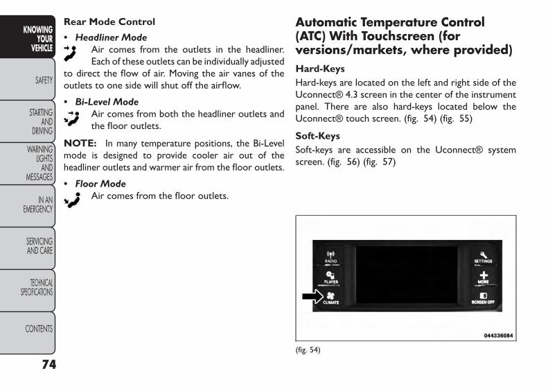
Rear Mode Control
• Headliner ModeAir comes from the outlets in the headliner.Each of these outlets can be individually adjusted
to direct the flow of air. Moving the air vanes of theoutlets to one side will shut off the airflow.
• Bi-Level ModeAir comes from both the headliner outlets andthe floor outlets.
NOTE: In many temperature positions, the Bi-Levelmode is designed to provide cooler air out of theheadliner outlets and warmer air from the floor outlets.
• Floor ModeAir comes from the floor outlets.
Automatic Temperature Control(ATC) With Touchscreen (forversions/markets, where provided)Hard-KeysHard-keys are located on the left and right side of theUconnect® 4.3 screen in the center of the instrumentpanel. There are also hard-keys located below theUconnect® touch screen. (fig. 54) (fig. 55)
Soft-KeysSoft-keys are accessible on the Uconnect® systemscreen. (fig. 56) (fig. 57)
(fig. 54)
74
KNOWINGYOUR
VEHICLE
SAFETY
STARTINGAND
DRIVING
WARNINGLIGHTS
ANDMESSAGES
IN ANEMERGENCY
SERVICINGAND CARE
TECHNICALSPECIFICATIONS
CONTENTS

Button Descriptions(AppliesTo Both Hard-keys And Soft-keys)
1. MAX A/C ButtonPress and release to change the current setting, theindicator illuminates when MAX A/C is ON. Perform-ing this function again will cause the MAX A/C opera-tion to switch into manual mode and the MAX A/Cindicator will turn off.
2. A/C ButtonPress and release to change the current setting, theindicator illuminates when A/C is ON. Performing thisfunction again will cause the A/C operation to switchinto manual mode and the A/C indicator will turn off.(fig. 55)
AutomaticTemperature Controls — Hard-Keys
(fig. 56)Uconnect® 4.3 Automatic 3 — ZoneTemperature
Controls — Soft-keys
(fig. 57)Uconnect® 8.4 Automatic 3 — ZoneTemperature
Controls — Soft-keys
75
KNOWINGYOURVEHICLE
SAFETY
STARTINGANDDRIVING
WARNINGLIGHTSANDMESSAGES
IN ANEMERGENCY
SERVICINGAND CARE
TECHNICALSPECIFICATIONS
CONTENTS

3. Recirculation ButtonPress and release to change the current setting, theindicator illuminates when ON.
4. AUTO Operation ButtonAutomatically controls the interior cabin temperatureby adjusting airflow distribution and amount. Perform-ing this function will cause the ATC to switch betweenmanual mode and automatic modes. Refer to “Auto-matic Operation” for more information.
5. Front Defrost ButtonPress and release to change the current airflow settingto Defrost mode. The indicator illuminates when thisfeature is ON. Performing this function will cause theATC to switch into manual mode. The blower speedmay increase when Defrost mode is selected. If thefront defrost mode is turned off the climate system willreturn the previous setting.
6. Rear Defrost ButtonPress and release this button to turn on the rearwindow defroster and the heated outside mirrors (forversions/markets, where provided). An indicator willilluminate when the rear window defroster is on. Therear window defroster automatically turns off after10 minutes.
Failure to follow these cautions cancause damage to the heating elements:• Use care when washing the inside of
the rear window. Do not use abrasive windowcleaners on the interior surface of the window.Use a soft cloth and a mild washing solution,wiping parallel to the heating elements. Labelscan be peeled off after soaking with warm water.• Do not use scrapers,sharp instruments,or abra-sive window cleaners on the interior surface ofthe window.• Keep all objects a safe distance from the win-dow.
7. Rear Climate Button (for versions/markets,where provided)Press and release this button to turn on the rearclimate controls. The indicator will illuminate when therear climate controls are ON. Performing this functionagain will turn OFF the rear climate controls.
8. PassengerTemperature Control Up ButtonProvides the passenger with independent temperaturecontrol. Push the button for warmer temperaturesettings.
NOTE: Pressing this button while in Sync mode willautomatically exit Sync.
76
KNOWINGYOUR
VEHICLE
SAFETY
STARTINGAND
DRIVING
WARNINGLIGHTS
ANDMESSAGES
IN ANEMERGENCY
SERVICINGAND CARE
TECHNICALSPECIFICATIONS
CONTENTS

9. PassengerTemperature Control Down ButtonProvides the passenger with independent temperaturecontrol. Push the button for cooler temperature set-tings.
NOTE: Pressing this button while in Sync mode willautomatically exit Sync.
10. SYNCPress the Sync soft-key to toggle the Sync featureOn/Off. The Sync indicator is illuminated when thisfeature is enabled. Sync is used to synchronize thepassenger temperature setting with the driver tem-perature setting. Changing the passenger temperaturesetting while in Sync will automatically exit this feature.
11. Blower ControlBlower control is used to regulate the amount of airforced through the climate system. There are sevenblower speeds available. Adjusting the blower willcause automatic mode to switch to manual operation.The speeds can be selected using either hard-keys orsoft-keys as follows:
Hard-key
The blower speed increases as you turn the controlclockwise from the lowest blower setting. The blowerspeed decreases as you turn the knob counter-clockwise.
Soft-key
Use the small blower icon to reduce the blower settingand the large blower icon to increase the blowersetting. Blower can also be selected by pressing theblower bar area between the icons.
12. ModesThe airflow distribution mode can be adjusted so aircomes from the instrument panel outlets, floor outlets,demist outlets and defrost outlets. The Mode settingsare as follows:
• Panel ModeAir comes from the outlets in the instrumentpanel. Each of these outlets can be individually
adjusted to direct the flow of air. The air vanes of thecenter outlets and outboard outlets can be moved up anddown or side to side to regulate airflow direction. Thereis a shut off wheel located below the air vanes to shut offor adjust the amount of airflow from these outlets.
• Bi-Level ModeAir comes from the instrument panel outlets andfloor outlets. A slight amount of air is directed
through the defrost and side window demister outlets.
NOTE: BI-LEVEL mode is designed under comfortconditions to provide cooler air out of the panel outletsand warmer air from the floor outlets.
77
KNOWINGYOURVEHICLE
SAFETY
STARTINGANDDRIVING
WARNINGLIGHTSANDMESSAGES
IN ANEMERGENCY
SERVICINGAND CARE
TECHNICALSPECIFICATIONS
CONTENTS

• Floor ModeAir comes from the floor outlets. A slightamount of air is directed through the defrost
and side window demister outlets.
• Mix ModeAir comes from the floor, defrost and side win-dow demist outlets. This mode works best incold or snowy conditions.
• Defrost ModeAir comes from the windshield and side windowdemist outlets. Use Defrost mode with maxi-
mum temperature settings for best windshield and sidewindow defrosting and defogging. When the defrostmode is selected, the blower level may will increase.
13. Climate Control OFF ButtonPress and release this button to turn the ClimateControl ON/OFF.
14. DriverTemperature Control Down ButtonProvides the driver with independent temperaturecontrol. Push the button for cooler temperature set-tings.
NOTE: In Sync mode, this button will also automati-cally adjust the passenger temperature setting at thesame time.
15. DriverTemperature Control Up ButtonProvides the driver with independent temperaturecontrol. Push the button for warmer temperaturesettings.
NOTE: In Sync mode, this button will also automati-cally adjust the passenger temperature setting at thesame time.
16. Temperature Control (Uconnect® 4.3 Only)Press the temperature soft-key to regulate the tem-perature of the air inside the passenger compartment.Moving the temperature bar into the red area, indicateswarmer temperatures. Moving the temperature barinto the blue area indicates cooler temperatures.
A/C (Air Conditioning)The Air Conditioning (A/C) button allows the opera-tor to manually activate or deactivate the air condition-ing system. When the air conditioning system is turnedon, cool dehumidified air will flow through the outletsinto the cabin. For improved fuel economy, press theA/C button to turn off the air conditioning and manu-ally adjust the blower and airflow mode settings. Also,make sure to select only Panel, Bi-Level or Floormodes.
78
KNOWINGYOUR
VEHICLE
SAFETY
STARTINGAND
DRIVING
WARNINGLIGHTS
ANDMESSAGES
IN ANEMERGENCY
SERVICINGAND CARE
TECHNICALSPECIFICATIONS
CONTENTS

NOTE:
• If fog or mist appears on the windshield or side glass,select Defrost mode and increase blower speed.
• If your air conditioning performance seems lowerthan expected, check the front of the A/C condenser(located in front of the radiator), for an accumulationof dirt or insects. Clean with a gentle water sprayfrom behind the radiator and through the condenser.Fabric front fascia protectors may reduce airflow tothe condenser, reducing air conditioning perfor-mance.
MAX A/C
MAX A/C sets the control for maximum cooling per-formance.
Press and release to toggle between MAX A/C and theprior settings. The soft-key illuminates when MAX A/Cis ON.
In MAX A/C, the blower level and mode position canbe adjusted to desired user settings. Pressing othersettings will cause the MAX A/C operation to switch tothe prior settings and the MAX A/C indicator will turnoff.
Recirculation Control
When outside air contains smoke, odors, orhigh humidity, or if rapid cooling is desired,you may wish to recirculate interior air bypressing the Recirculation control button.
The recirculation indicator will illuminate when thisbutton is selected. Push the button a second time toturn off the Recirculation mode and allow outside airinto the vehicle.
NOTE: In cold weather, use of Recirculation modemay lead to excessive window fogging. The recircula-tion feature may be unavailable (soft button greyedout). The Recirculation mode is not allowed in Defrostmode to improve window clearing operation. Recircu-lation will be disabled automatically if this mode isselected. Attempting to use Recirculation while in thismode will cause the LED in the control button to blinkand then turn off.
79
KNOWINGYOURVEHICLE
SAFETY
STARTINGANDDRIVING
WARNINGLIGHTSANDMESSAGES
IN ANEMERGENCY
SERVICINGAND CARE
TECHNICALSPECIFICATIONS
CONTENTS

AutomaticTemperature Control (ATC)
Automatic Operation
1. Press the AUTO hard-key or soft-key button (4) onthe Automatic Temperature Control (ATC) Panel.
2. Next, adjust the temperature you would like thesystem to maintain by adjusting the driver and pas-senger temperature hard or soft control buttons(7, 8, 13, 14). Once the desired temperature isdisplayed, the system will achieve and automaticallymaintain that comfort level.
3. When the system is set up for your comfort level, itis not necessary to change the settings. You willexperience the greatest efficiency by simply allowingthe system to function automatically.
NOTE:
• It is not necessary to move the temperature settingsfor cold or hot vehicles. The system automaticallyadjusts the temperature, mode, and blower speed toprovide comfort as quickly as possible.
• The temperature can be displayed in U.S. or Metricunits by selecting the US/M customer-programmablefeature. Refer to the “Uconnect® System Settings”in this section of the manual.
To provide you with maximum comfort in the Auto-matic mode, during cold start-ups the blower fan willremain on low until the engine warms up. The blowerwill increase in speed and transition into Auto mode.
Manual Operation OverrideThe system allows for manual selection of blowerspeed, air distribution mode, A/C status and recircula-tion control.
The blower fan speed can be set to any fixed speed byadjusting the blower control. The fan will now operateat a fixed speed until additional speeds are selected.This allows the front occupants to control the volumeof air circulated in the vehicle and cancel the Automode.
The operator can also select the direction of theairflow by selecting one of the available mode settings.A/C operation and Recirculation control can also bemanually selected in Manual operation.
80
KNOWINGYOUR
VEHICLE
SAFETY
STARTINGAND
DRIVING
WARNINGLIGHTS
ANDMESSAGES
IN ANEMERGENCY
SERVICINGAND CARE
TECHNICALSPECIFICATIONS
CONTENTS

Rear Automatic TemperatureControl (ATC) (for versions/markets, where provided)The rear ATC system has floor air outlets at the rearright side of the 3rd Row seats and overhead outlets ateach outboard rear seating position. The system pro-vides heated air through the floor outlets or cool,dehumidified air through the headliner outlets.
The rear system temperature control soft-keys arelocated in the Uconnect® touch system, located onthe instrument panel. (fig. 58) (fig. 59)
ControllingThe Rear Climate Controls FromThe Front ATC PanelThe Three-Zone ATC system allows for adjustment ofthe rear climate controls from the front ATC panel.
To change the rear system settings:
• Press "REAR" button to change control to rearcontrol mode, Rear display (below) will appear. Con-trol functions now operate rear system.
• To return to Front screen, press "REAR" buttonagain, or it will revert to the Front screen after sixseconds.
(fig. 58)Uconnect® 4.3 Automatic Rear Climate Soft-Key
Controls Screen
1 — Blower Up Soft-Key 2 — Mode Soft-Key3 — Temperature Soft-Key 4 — Blower Down Soft-Key5 — Done Soft-Key 6 — Rear Lock Soft-Key7 — Rear Auto Soft-Key 8 — Rear Off Soft-Key
81
KNOWINGYOURVEHICLE
SAFETY
STARTINGANDDRIVING
WARNINGLIGHTSANDMESSAGES
IN ANEMERGENCY
SERVICINGAND CARE
TECHNICALSPECIFICATIONS
CONTENTS
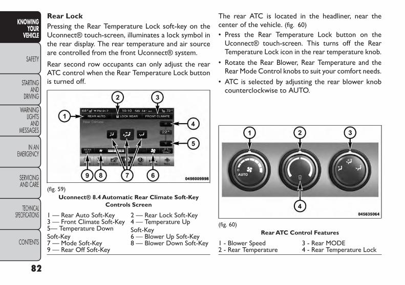
Rear LockPressing the Rear Temperature Lock soft-key on theUconnect® touch-screen, illuminates a lock symbol inthe rear display. The rear temperature and air sourceare controlled from the front Uconnect® system.
Rear second row occupants can only adjust the rearATC control when the Rear Temperature Lock buttonis turned off.
The rear ATC is located in the headliner, near thecenter of the vehicle. (fig. 60)
• Press the Rear Temperature Lock button on theUconnect® touch-screen. This turns off the RearTemperature Lock icon in the rear temperature knob.
• Rotate the Rear Blower, Rear Temperature and theRear Mode Control knobs to suit your comfort needs.
• ATC is selected by adjusting the rear blower knobcounterclockwise to AUTO.
(fig. 59)Uconnect® 8.4 Automatic Rear Climate Soft-Key
Controls Screen
1 — Rear Auto Soft-Key 2 — Rear Lock Soft-Key3 — Front Climate Soft-Key 4 — Temperature Up
Soft-Key5— Temperature DownSoft-Key 6 — Blower Up Soft-Key7 — Mode Soft-Key 8 — Blower Down Soft-Key9 — Rear Off Soft-Key
(fig. 60)Rear ATC Control Features
1 - Blower Speed 3 - Rear MODE2 - Rear Temperature 4 - Rear Temperature Lock
82
KNOWINGYOUR
VEHICLE
SAFETY
STARTINGAND
DRIVING
WARNINGLIGHTS
ANDMESSAGES
IN ANEMERGENCY
SERVICINGAND CARE
TECHNICALSPECIFICATIONS
CONTENTS
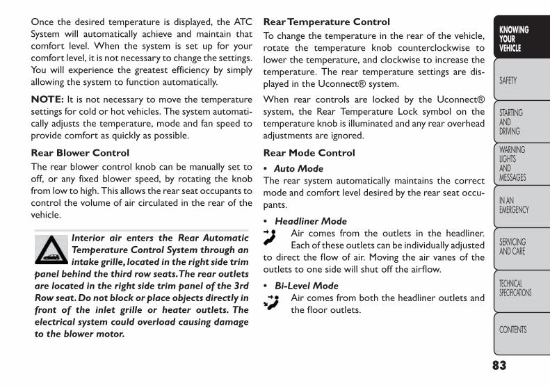
Once the desired temperature is displayed, the ATCSystem will automatically achieve and maintain thatcomfort level. When the system is set up for yourcomfort level, it is not necessary to change the settings.You will experience the greatest efficiency by simplyallowing the system to function automatically.
NOTE: It is not necessary to move the temperaturesettings for cold or hot vehicles. The system automati-cally adjusts the temperature, mode and fan speed toprovide comfort as quickly as possible.
Rear Blower ControlThe rear blower control knob can be manually set tooff, or any fixed blower speed, by rotating the knobfrom low to high. This allows the rear seat occupants tocontrol the volume of air circulated in the rear of thevehicle.
Interior air enters the Rear AutomaticTemperature Control System through anintake grille, located in the right side trim
panel behind the third row seats.The rear outletsare located in the right side trim panel of the 3rdRow seat.Do not block or place objects directly infront of the inlet grille or heater outlets. Theelectrical system could overload causing damageto the blower motor.
RearTemperature ControlTo change the temperature in the rear of the vehicle,rotate the temperature knob counterclockwise tolower the temperature, and clockwise to increase thetemperature. The rear temperature settings are dis-played in the Uconnect® system.
When rear controls are locked by the Uconnect®system, the Rear Temperature Lock symbol on thetemperature knob is illuminated and any rear overheadadjustments are ignored.
Rear Mode Control
• Auto ModeThe rear system automatically maintains the correctmode and comfort level desired by the rear seat occu-pants.
• Headliner ModeAir comes from the outlets in the headliner.Each of these outlets can be individually adjusted
to direct the flow of air. Moving the air vanes of theoutlets to one side will shut off the airflow.
• Bi-Level ModeAir comes from both the headliner outlets andthe floor outlets.
83
KNOWINGYOURVEHICLE
SAFETY
STARTINGANDDRIVING
WARNINGLIGHTSANDMESSAGES
IN ANEMERGENCY
SERVICINGAND CARE
TECHNICALSPECIFICATIONS
CONTENTS

NOTE: In many temperature positions, the BI-LEVELmode is designed to provide cooler air out of the head-liner outlets and warmer air from the floor outlets.
• Floor ModeAir comes from the floor outlets.
OperatingTips
NOTE: Refer to the chart at the end of this section forsuggested control settings for various weather condi-tions.
Summer OperationThe engine cooling system must be protected with ahigh-quality antifreeze coolant to provide proper cor-rosion protection and to protect against engine over-heating. A solution of 50% OAT (Organic AdditiveTechnology) coolant that meets the requirements ofFiat Classification 9.55522 and 50% water is recom-mended. Refer to “Maintenance Procedures” in “Ser-vice and Care” for proper coolant selection.
Winter OperationUse of the air Recirculation mode during Wintermonths is not recommended because it may causewindow fogging.
Vacation StorageAny time you store your vehicle or keep it out ofservice (i.e., vacation) for two weeks or more, run theair conditioning system at idle for about five minutes inthe fresh air and high blower setting. This will ensureadequate system lubrication to minimize the possibilityof compressor damage when the system is startedagain.
Window FoggingInterior fogging on the windshield can be quickly re-moved by turning the mode selector to Defrost. TheDefrost/Floor mode can be used to maintain a clearwindshield and provide sufficient heating. If side win-dow fogging becomes a problem, increase the blowerspeed. Vehicle windows tend to fog on the inside inmild but rainy or humid weather.
NOTE:
• Recirculation mode without A/C should not be usedfor long periods, as fogging may occur.
• Automatic Temperature Controls (ATC) will auto-matically adjust the climate control settings to re-duce or eliminate window fogging on the front wind-shield. When this occurs, recirculation will beunavailable.
84
KNOWINGYOUR
VEHICLE
SAFETY
STARTINGAND
DRIVING
WARNINGLIGHTS
ANDMESSAGES
IN ANEMERGENCY
SERVICINGAND CARE
TECHNICALSPECIFICATIONS
CONTENTS

Outside Air IntakeMake sure the air intake, located directly in front of thewindshield, is free of obstructions such as leaves.Leaves collected in the air intake may reduce airflow,and if they enter the plenum, they could plug the waterdrains. In winter months, make sure the air intake isclear of ice, slush, and snow.
A/C Air FilterThe climate control system filters outside air contain-ing dust, pollen and some odors. Strong odors cannotbe totally filtered out. Refer to “Maintenance Proce-dures” in “Servicing and Care” for filter replacementinstructions.
Manual Control Setting Suggestions ForVarious Weather Conditions(fig. 61)
(fig. 61)
85
KNOWINGYOURVEHICLE
SAFETY
STARTINGANDDRIVING
WARNINGLIGHTSANDMESSAGES
IN ANEMERGENCY
SERVICINGAND CARE
TECHNICALSPECIFICATIONS
CONTENTS

LIGHTSHEADLIGHT SWITCH
The headlight switch is located on the left side ofthe instrument panel. This switch controls theoperation of the headlights, parking lights, in-
strument panel lights, instrument panel light dimming,interior lights and fog lights. (fig. 62)
Rotate the headlight switch clockwise to the firstdetent for parking light and instrument panel lightoperation. Rotate the headlight switch to the seconddetent for headlight, parking light and instrument panellight operation.
AUTOMATIC HEADLIGHTS(for versions/markets, where provided)This system automatically turns the headlights on or offaccording to ambient light levels. To turn the systemon, rotate the headlight switch counterclockwise tothe AUTO position. When the system is on, theheadlight time delay feature is also on. This means theheadlights will stay on for up to 90 seconds after youturn the ignition switch OFF. To turn the automaticsystem off, move the headlight switch out of the AUTOposition.
NOTE: The engine must be running before the head-lights will come on in the automatic mode.
HEADLIGHTS ON WITH WIPERS(AVAILABLE WITH AUTOMATICHEADLIGHTS ONLY)When this feature is active, the headlights will turn onapproximately 10 seconds after the wipers are turnedon if the headlight switch is placed in the AUTOposition. In addition, the headlights will turn off whenthe wipers are turned off if they were turned on by thisfeature.
NOTE: The Headlights On with Wipers feature can beturned on and off using the Uconnect® System, referto “Uconnect® Settings” in “Knowing Your Vehicle”for further information.(fig. 62)
Headlight Switch
86
KNOWINGYOUR
VEHICLE
SAFETY
STARTINGAND
DRIVING
WARNINGLIGHTS
ANDMESSAGES
IN ANEMERGENCY
SERVICINGAND CARE
TECHNICALSPECIFICATIONS
CONTENTS

HEADLIGHTTIME DELAYThis feature provides the safety of headlight illumina-tion for up to 90 seconds when leaving your vehicle inan unlit area.
To activate the delay feature, turn OFF the ignitionswitch while the headlights are still on. Then, turn offthe headlights within 45 seconds. The delay intervalbegins when the headlight switch is turned off.
NOTE: The lights must be turned off within 45 secondsof turning the ignition OFF to activate this feature.
If you turn the headlights, park lights or ignition switchON again, the system will cancel the delay.
If you turn the headlights off before the ignition, theywill turn off in the normal manner.
NOTE: The Headlight Time Delay is programmableusing the Uconnect® System, refer to “Uconnect® Set-tings” in “Knowing Your Vehicle” for further information.
LIGHTS-ON REMINDERIf the headlights or parking lights are on after theignition is turned OFF, a chime will sound to alert thedriver when the driver's door is opened.
FRONT AND REAR FOG LIGHTS(for versions/markets, where provided)The front and rear fog light switch is built into theheadlight switch. (fig. 63)
The front and rear fog lights may be operated asdesired when visibility is poor due to fog. The foglights will activate in the following order: Pressthe headlight switch once and the front fog lightscome on. Press the switch a second time and the
rear fog lights will come on (front fog lights stay on).Press the switch a third time and the rear fog lights turnoff (front fog stays on). Press the switch a fourth timesand the front fog turns off. For vehicles without front fog,rear fog will activate on the first press.
An indicator light in the instrument cluster illuminateswhen the fog lights are turned on.
(fig. 63)Fog Light Switch
87
KNOWINGYOURVEHICLE
SAFETY
STARTINGANDDRIVING
WARNINGLIGHTSANDMESSAGES
IN ANEMERGENCY
SERVICINGAND CARE
TECHNICALSPECIFICATIONS
CONTENTS

MULTIFUNCTION LEVERThe multifunction lever controls the operation of theturn signals, headlight beam selection and passing lights.The multifunction lever is located on the left side of thesteering column. (fig. 64)
TURN SIGNALSMove the multifunction lever up or down and thearrows on each side of the instrument cluster flash toshow proper operation of the front and rear turn signallights.
NOTE:
• If either light remains on and does not flash, or thereis a very fast flash rate, check for a defective outsidelight bulb. If an indicator fails to light when the leveris moved, it would suggest that the indicator bulb isdefective.
• A “Turn Signal On” message will appear in the EVIC(for versions/markets, where provided) and a con-tinuous chime will sound if the vehicle is driven morethan 1.6 km with either turn signal on.
LANE CHANGE ASSISTTap the lever up or down once, without moving beyondthe detent, and the turn signal (right or left) will flashthree times then automatically turn off.
HIGH/LOW BEAM SWITCHPush the multifunction lever away from you to switchthe headlights to high beam. Pull the multifunction levertoward you to switch the headlights back to low beam.
(fig. 64)Multifunction Lever
88
KNOWINGYOUR
VEHICLE
SAFETY
STARTINGAND
DRIVING
WARNINGLIGHTS
ANDMESSAGES
IN ANEMERGENCY
SERVICINGAND CARE
TECHNICALSPECIFICATIONS
CONTENTS

FLASH-TO-PASSYou can signal another vehicle with your headlights bylightly pulling the multifunction lever toward you. Thiswill turn on the high beams headlights until the lever isreleased.
INTERIOR LIGHTSThe interior lights come on when a door is opened.
To protect the battery, the interior lights will turn offautomatically 10 minutes after the ignition switch ismoved to the LOCK position. This will occur if theinterior lights were switched on manually or are onbecause a door is open. This includes the glove boxlight, but not the trunk light. To restore interior lightoperation, either turn the ignition switch ON or cyclethe light switch.
DIMMER CONTROLSThe dimmer control is part of the headlight switch andis located on the left side of the instrument panel.(fig. 65)
Rotating the left dimmer control upward with theparking lights or headlights on will increase the bright-ness of the instrument panel lights.
(fig. 65)Dimmer Controls
89
KNOWINGYOURVEHICLE
SAFETY
STARTINGANDDRIVING
WARNINGLIGHTSANDMESSAGES
IN ANEMERGENCY
SERVICINGAND CARE
TECHNICALSPECIFICATIONS
CONTENTS

DOME LIGHT POSITIONRotate the dimmer control completely upward to thesecond detent to turn on the interior lights. Theinterior lights will remain on when the dimmer controlis in this position.
INTERIOR LIGHT DEFEAT (OFF)Rotate the dimmer control to the extreme bottom offposition. The interior lights will remain off when thedoors are open.
PARADE MODE (DAYTIME BRIGHTNESSFEATURE)Rotate the dimmer control upward to the first detent.This feature brightens all text displays such as theodometer, and radio when the parking lights or head-lights are on.
HEADLIGHT LEVELING SYSTEMThis system allows the driver to maintain proper head-light beam position with the road surface regardless ofvehicle load.
The headlight leveling switch is located nextto the dimmer control on the left side of theinstrument panel.
To operate, rotate the headlight leveling switch untilthe appropriate number, which corresponds to theload listed on the following chart, illuminates on theswitch.
0 Driver only, or driver and front passenger.
1
Driver, plus an evenly distributed load inthe luggage compartment. The totalweight of the driver and load does notexceed the maximum load capacity ofthe vehicle.
2
All seating positions occupied, plus anevenly distributed load in the luggagecompartment. The total weight ofpassengers and load does not exceed themaximum load capacity of the vehicle.
Calculations based on a passenger weight of 75 kg.
MAP/READING LIGHTSRefer to “Overhead Console” for further informationon Map/Reading Lights.
90
KNOWINGYOUR
VEHICLE
SAFETY
STARTINGAND
DRIVING
WARNINGLIGHTS
ANDMESSAGES
IN ANEMERGENCY
SERVICINGAND CARE
TECHNICALSPECIFICATIONS
CONTENTS

ILLUMINATED ENTRYThe courtesy lights will turn on when you use theRemote Keyless Entry (RKE) transmitter to unlock thedoors or open any door or liftgate.
This feature also turns on the approach lighting in theoutside mirrors (for versions/markets, where pro-vided). Refer to “Mirrors” in “Knowing Your Vehicle”for further information.
The interior lights will fade to off after approximately30 seconds or they will immediately fade to off oncethe ignition is cycled to the ON/RUN position from theOFF position.
NOTE:
• The front courtesy overhead console and door cour-tesy lights will turn on if the dimmer control is in the"Dome ON" position (extreme top position).
• The Illuminated Entry system will not operate if thedimmer control is in the “Dome defeat” position(extreme bottom position).
WINDSHIELD WIPERS ANDWASHERSThe windshield wiper/washer control lever is locatedon the left side of the steering column. (fig. 66)
The front wipers are operated by rotating a switch,located at the end of the lever. Refer to “Rear WindowFeatures” for further information on using the rearwindow wiper/washer.
(fig. 66)Windshield Wiper/Washer Lever
91
KNOWINGYOURVEHICLE
SAFETY
STARTINGANDDRIVING
WARNINGLIGHTSANDMESSAGES
IN ANEMERGENCY
SERVICINGAND CARE
TECHNICALSPECIFICATIONS
CONTENTS
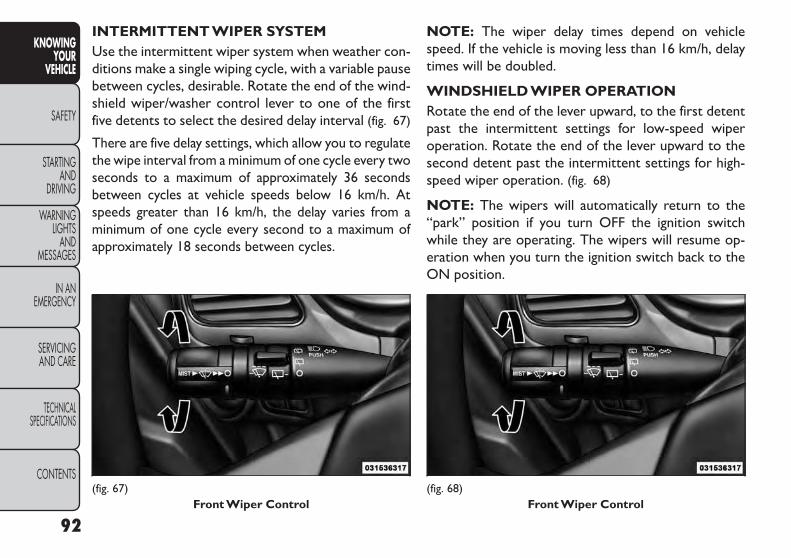
INTERMITTENT WIPER SYSTEMUse the intermittent wiper system when weather con-ditions make a single wiping cycle, with a variable pausebetween cycles, desirable. Rotate the end of the wind-shield wiper/washer control lever to one of the firstfive detents to select the desired delay interval (fig. 67)
There are five delay settings, which allow you to regulatethe wipe interval from a minimum of one cycle every twoseconds to a maximum of approximately 36 secondsbetween cycles at vehicle speeds below 16 km/h. Atspeeds greater than 16 km/h, the delay varies from aminimum of one cycle every second to a maximum ofapproximately 18 seconds between cycles.
NOTE: The wiper delay times depend on vehiclespeed. If the vehicle is moving less than 16 km/h, delaytimes will be doubled.
WINDSHIELD WIPER OPERATIONRotate the end of the lever upward, to the first detentpast the intermittent settings for low-speed wiperoperation. Rotate the end of the lever upward to thesecond detent past the intermittent settings for high-speed wiper operation. (fig. 68)
NOTE: The wipers will automatically return to the“park” position if you turn OFF the ignition switchwhile they are operating. The wipers will resume op-eration when you turn the ignition switch back to theON position.
(fig. 67)Front Wiper Control
(fig. 68)Front Wiper Control
92
KNOWINGYOUR
VEHICLE
SAFETY
STARTINGAND
DRIVING
WARNINGLIGHTS
ANDMESSAGES
IN ANEMERGENCY
SERVICINGAND CARE
TECHNICALSPECIFICATIONS
CONTENTS

• Turn the windshield wipers OFF whendriving through an automatic car wash.Damage to the windshield wipers may
result if the wiper control is left in any positionother than OFF.• In cold weather, always turn OFF the wiperswitch and allow the wipers to return to the parkposition before turning OFF the engine. If thewiper switch is left ON and the wipers freeze tothe windshield, damage to the wiper motor mayoccur when the vehicle is restarted.• Always remove any buildup of snow that pre-vents the windshield wiper blades from returningto the “park” position. If the windshield wipercontrol is turned OFF, and the blades cannotreturn to the“park”position,damage to the wipermotor may occur.
WINDSHIELD WASHERSTo use the windshield washer, push the washer knob,located on the end of the multifunction lever, inward tothe second detent.
If you activate the washer while the wiper control is inthe delay range, the wipers will operate in low-speedfor two or three wipe cycles after releasing the leverand then resume the intermittent interval previouslyselected.
If you activate the washer while the wiper control is inthe OFF position, the wipers will operate for two orthree wipe cycles and then turn OFF.
WARNING!Sudden loss of visibility through thewindshield could lead to a collision.You
might not see other vehicles or other obstacles.To avoid sudden icing of the windshield duringfreezing weather, warm the windshield with thedefroster before and during windshield washeruse.
MIST FEATUREPush the washer knob, located on the end of themultifunction lever, inward to the first detent to acti-vate a single wipe cycle to clear the windshield of roadmist or spray from a passing vehicle. The wipers willcontinue to operate until you release the lever.
NOTE: The mist feature does not activate the washerpump; therefore, no washer fluid will be sprayed on thewindshield. The wash function must be used in order tospray the windshield with washer fluid.
93
KNOWINGYOURVEHICLE
SAFETY
STARTINGANDDRIVING
WARNINGLIGHTSANDMESSAGES
IN ANEMERGENCY
SERVICINGAND CARE
TECHNICALSPECIFICATIONS
CONTENTS

HEADLIGHT WASHERS(for versions/markets, whereprovided)The Headlight Washers are recessed into the top ofthe fascia, centrally located below each headlight.
The windshield wiper/washer control lever operatesthe headlight washers when the ignition switch is in theON position and the headlights are ON. The lever islocated on the left side of the steering column.
To use the headlight washers, push the washer knob,located on the end of the multifunction lever, inward tothe second detent to activate the windshield washersand release it. When this is done, the two stationarywasher nozzles at each headlight spray one timedhigh-pressure spray of washer fluid onto each headlightlens. In addition, the windshield washers will spray thewindshield and the windshield wipers will cycle.
NOTE: After turning the ignition switch and head-lights ON, the headlight washers will operate on thefirst spray of the windshield washer and then everyeleventh spray after that.
REAR WINDOW FEATURESREAR WINDOW WIPER/WASHERThe rear window wiper/washer control is located onthe right side of the steering column. (fig. 69)
Rotate the switch upward to the first detentposition for rear wiper operation.
NOTE: The rear wiper operates in an intermittentmode only.
(fig. 69)Rear Wiper/Washer
94
KNOWINGYOUR
VEHICLE
SAFETY
STARTINGAND
DRIVING
WARNINGLIGHTS
ANDMESSAGES
IN ANEMERGENCY
SERVICINGAND CARE
TECHNICALSPECIFICATIONS
CONTENTS

Rotate the switch upward past the first detentposition to activate the rear washer. The washer
pump will continue to operate as long as the switch isheld. Upon release, the wiper will cycle three timesbefore returning to the set position. (fig. 70)
If the rear wiper is operating when the ignition isturned to the LOCK position, the wiper will automati-cally return to the “Park” position. When the vehicle isrestarted, the wiper will resume function at whicheverposition the switch is set at.
• Turn the rear wiper off when drivingthrough an automatic car wash.Damageto the rear wiper may result if the rear
wiper switch is left in the ON position.• In cold weather, always turn off the rear wiperswitch and allow the rear wiper to return to thepark position before turning off the engine. If therear wiper switch is left on and the rear wiperfreezes to the window, damage to the rear wipermotor may occur when the vehicle is restarted.• Always remove any buildup of snow that pre-vents the rear wiper blade from returning to thepark position. If the rear wiper control is turnedoff and the blade cannot return to the parkposition, damage to the rear wiper motor mayoccur.
(fig. 70)Rear Wiper/Washer Control
95
KNOWINGYOURVEHICLE
SAFETY
STARTINGANDDRIVING
WARNINGLIGHTSANDMESSAGES
IN ANEMERGENCY
SERVICINGAND CARE
TECHNICALSPECIFICATIONS
CONTENTS
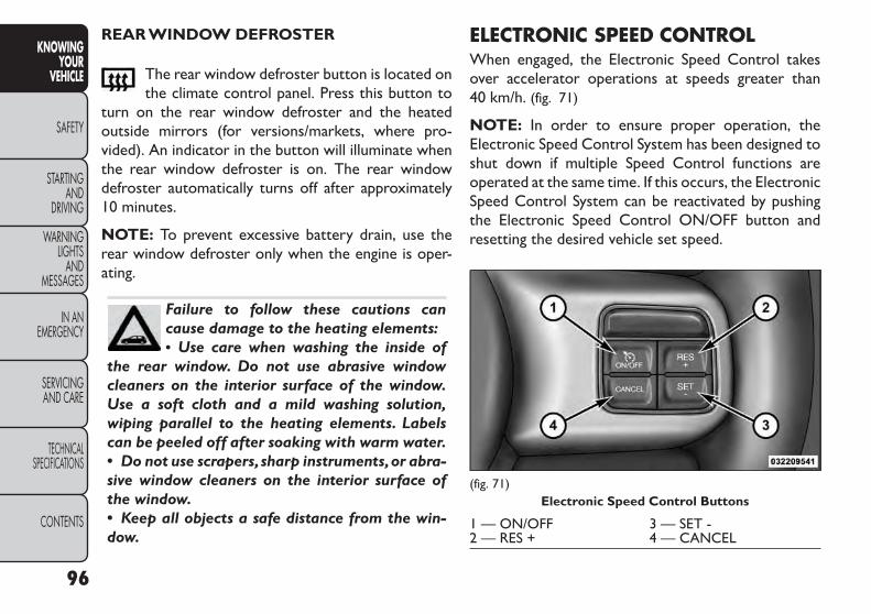
REAR WINDOW DEFROSTER
The rear window defroster button is located onthe climate control panel. Press this button to
turn on the rear window defroster and the heatedoutside mirrors (for versions/markets, where pro-vided). An indicator in the button will illuminate whenthe rear window defroster is on. The rear windowdefroster automatically turns off after approximately10 minutes.
NOTE: To prevent excessive battery drain, use therear window defroster only when the engine is oper-ating.
Failure to follow these cautions cancause damage to the heating elements:• Use care when washing the inside of
the rear window. Do not use abrasive windowcleaners on the interior surface of the window.Use a soft cloth and a mild washing solution,wiping parallel to the heating elements. Labelscan be peeled off after soaking with warm water.• Do not use scrapers,sharp instruments,or abra-sive window cleaners on the interior surface ofthe window.• Keep all objects a safe distance from the win-dow.
ELECTRONIC SPEED CONTROLWhen engaged, the Electronic Speed Control takesover accelerator operations at speeds greater than40 km/h. (fig. 71)
NOTE: In order to ensure proper operation, theElectronic Speed Control System has been designed toshut down if multiple Speed Control functions areoperated at the same time. If this occurs, the ElectronicSpeed Control System can be reactivated by pushingthe Electronic Speed Control ON/OFF button andresetting the desired vehicle set speed.
(fig. 71)Electronic Speed Control Buttons
1 — ON/OFF 3 — SET -2 — RES + 4 — CANCEL
96
KNOWINGYOUR
VEHICLE
SAFETY
STARTINGAND
DRIVING
WARNINGLIGHTS
ANDMESSAGES
IN ANEMERGENCY
SERVICINGAND CARE
TECHNICALSPECIFICATIONS
CONTENTS

TO ACTIVATEPush the ON/OFF button. The Cruise Indicator Lightin the instrument cluster will illuminate. To turn thesystem off, push the ON/OFF button a second time.The Cruise Indicator Light will turn off. The systemshould be turned off when not in use.
WARNING!Leaving the Electronic Speed Controlsystem on when not in use is dangerous.
You could accidentally set the system or cause itto go faster than you want.You could lose controland have an accident. Always leave the systemOFF when you are not using it.
TO SET A DESIRED SPEEDTurn the Electronic Speed Control ON. When thevehicle has reached the desired speed, press the SET (-)button and release. Release the accelerator and thevehicle will operate at the selected speed.
NOTE: The vehicle should be traveling at a steadyspeed and on level ground before pressing the SETbutton.
TO DEACTIVATEA soft tap on the brake pedal, pushing the CANCELbutton, or normal brake pressure while slowing the
vehicle will deactivate Electronic Speed Control with-out erasing the set speed memory. Pressing the ON/OFF button or turning the ignition switch OFF erasesthe set speed memory.
TO RESUME SPEEDTo resume a previously set speed, push the RES (+)button and release. Resume can be used at any speedabove 32 km/h.
TOVARYTHE SPEED SETTINGWhen the Electronic Speed Control is set, you canincrease speed by pushing the RES (+) button. If thebutton is continually pressed, the set speed will con-tinue to increase until the button is released, then thenew set speed will be established.
Pressing the RES (+) button once will result in a1.6 km/h increase in set speed. Each subsequent tap ofthe button results in an increase of 1.6 km/h.
To decrease speed while the Electronic Speed Controlis set, push the SET (-) button. If the button is continu-ally held in the SET (-) position, the set speed willcontinue to decrease until the button is released.Release the button when the desired speed is reached,and the new set speed will be established.
Pressing the SET (-) button once will result in a1.6 km/h decrease in set speed. Each subsequent tap ofthe button results in a decrease of 1.6 km/h.
97
KNOWINGYOURVEHICLE
SAFETY
STARTINGANDDRIVING
WARNINGLIGHTSANDMESSAGES
IN ANEMERGENCY
SERVICINGAND CARE
TECHNICALSPECIFICATIONS
CONTENTS

TO ACCELERATE FOR PASSINGPress the accelerator as you would normally. When thepedal is released, the vehicle will return to the setspeed.
Using Electronic Speed Control On HillsThe transmission may downshift on hills to maintainthe vehicle set speed.
NOTE: The Electronic Speed Control system main-tains speed up and down hills. A slight speed change onmoderate hills is normal.
On steep hills, a greater speed loss or gain may occurso it may be preferable to drive without ElectronicSpeed Control.
WARNING!Electronic Speed Control can be danger-ous where the system cannot maintain a
constant speed.Your vehicle could go too fast forthe conditions, and you could lose control andhave an accident. Do not use Electronic SpeedControl in heavy traffic or on roads that arewinding, icy, snow-covered or slippery.
OVERHEAD CONSOLEThe overhead console contains courtesy/reading lights,storage for sunglasses, an interior observation mirrorand an optional power sunroof switch. (fig. 72)
(fig. 72)Overhead Console
98
KNOWINGYOUR
VEHICLE
SAFETY
STARTINGAND
DRIVING
WARNINGLIGHTS
ANDMESSAGES
IN ANEMERGENCY
SERVICINGAND CARE
TECHNICALSPECIFICATIONS
CONTENTS

COURTESY/READING LIGHTSThe overhead console has two courtesy lights. Thelights turn on when a door or the liftgate is opened.If your vehicle is equipped with Remote Keyless Entry(RKE) the lights will also turn on when the UNLOCKbutton on the RKE transmitter is pressed. The cour-tesy lights also function as reading lights. Press in oneach lens to turn these lights on while inside thevehicle. Press the lens a second time to turn each lightoff. You may adjust the direction of these lights bypressing the outside ring, which is identified with fourdirectional arrows. (fig. 73)
SUNGLASSES STORAGETo access the storage compartment, press on theraised bars on the compartment door in the center ofthe console and release and the door will swing down-ward. (fig. 74)
(fig. 73)Courtesy/Reading Light
(fig. 74)Sunglasses Storage Compartment
99
KNOWINGYOURVEHICLE
SAFETY
STARTINGANDDRIVING
WARNINGLIGHTSANDMESSAGES
IN ANEMERGENCY
SERVICINGAND CARE
TECHNICALSPECIFICATIONS
CONTENTS

INTERIOR OBSERVATION MIRRORThe convex interior observation mirror provides thedriver and front seat passenger a wide field of view toconveniently view passengers sitting in the rear passen-ger seats. To use the interior observation mirror, presson the raised bars on the compartment door andrelease (the door will swing downward), then raise thedoor until it is almost closed and release. The door willlatch in position to use the interior observation mirror.
NOTE: From the “observation mirror” position, thedoor can only be closed.
To return to the full open position, the door must firstbe closed and then opened by pressing the latch againto release. (fig. 75)
POWER SUNROOF SWITCH(for versions/markets, where provided)Refer to “Power Sunroof” for further information.
(fig. 75)Observation Mirror
100
KNOWINGYOUR
VEHICLE
SAFETY
STARTINGAND
DRIVING
WARNINGLIGHTS
ANDMESSAGES
IN ANEMERGENCY
SERVICINGAND CARE
TECHNICALSPECIFICATIONS
CONTENTS
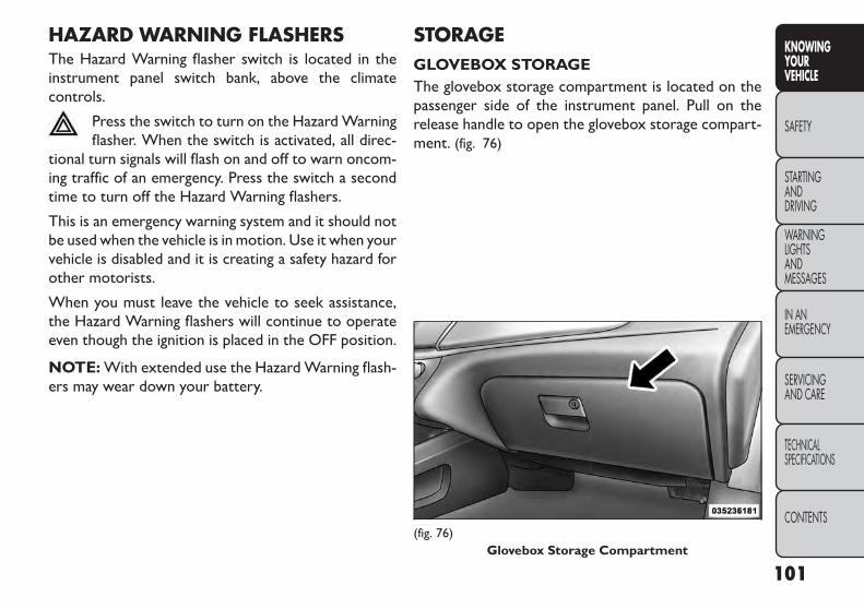
HAZARD WARNING FLASHERSThe Hazard Warning flasher switch is located in theinstrument panel switch bank, above the climatecontrols.
Press the switch to turn on the Hazard Warningflasher. When the switch is activated, all direc-
tional turn signals will flash on and off to warn oncom-ing traffic of an emergency. Press the switch a secondtime to turn off the Hazard Warning flashers.
This is an emergency warning system and it should notbe used when the vehicle is in motion. Use it when yourvehicle is disabled and it is creating a safety hazard forother motorists.
When you must leave the vehicle to seek assistance,the Hazard Warning flashers will continue to operateeven though the ignition is placed in the OFF position.
NOTE: With extended use the Hazard Warning flash-ers may wear down your battery.
STORAGEGLOVEBOX STORAGEThe glovebox storage compartment is located on thepassenger side of the instrument panel. Pull on therelease handle to open the glovebox storage compart-ment. (fig. 76)
(fig. 76)Glovebox Storage Compartment
101
KNOWINGYOURVEHICLE
SAFETY
STARTINGANDDRIVING
WARNINGLIGHTSANDMESSAGES
IN ANEMERGENCY
SERVICINGAND CARE
TECHNICALSPECIFICATIONS
CONTENTS

FLOOR CONSOLE STORAGEAn open storage area, or cubby bin, is located in thefloor console. (fig. 77)
CENTER CONSOLE STORAGEThere is a storage compartment located under thecenter console armrest. (fig. 78)
Pull upward on the release handle, located on the frontof the lid, to open the storage compartment. (fig. 79)
(fig. 77)Floor Console Cubby Bin
(fig. 78)Center Console
(fig. 79)Opened Storage Compartment
102
KNOWINGYOUR
VEHICLE
SAFETY
STARTINGAND
DRIVING
WARNINGLIGHTS
ANDMESSAGES
IN ANEMERGENCY
SERVICINGAND CARE
TECHNICALSPECIFICATIONS
CONTENTS

WARNING!Do not operate this vehicle with a con-sole compartment lid in the open posi-
tion. Cellular phones, music players, and otherhandheld electronic devices should be stowedwhile driving. Use of these devices while drivingcan cause an accident due to distraction, result-ing in death or injury.
Sliding Armrest (for automatic transmissiononly)The center console armrest can also be slid rearwardfor easy access to the storage area. (fig. 80)
FLIP 'N STOW™ FRONT PASSENGER SEATSTORAGE (for versions/markets, whereprovided)The seat latch release-loop is located in the center ofthe seat cushion between the seat cushion and theseatback. Pull the loop upward to release the latch andthen forward to open the seat to the detent position.(fig. 81)
NOTE: Make sure that objects inside the bin do notinterfere with the latch before closing the seat. Pushthe seat cushion downward after closing it to makesure it latches to the base.
(fig. 80)Sliding Armrest
(fig. 81)Front Passenger Seat Storage Compartment
103
KNOWINGYOURVEHICLE
SAFETY
STARTINGANDDRIVING
WARNINGLIGHTSANDMESSAGES
IN ANEMERGENCY
SERVICINGAND CARE
TECHNICALSPECIFICATIONS
CONTENTS
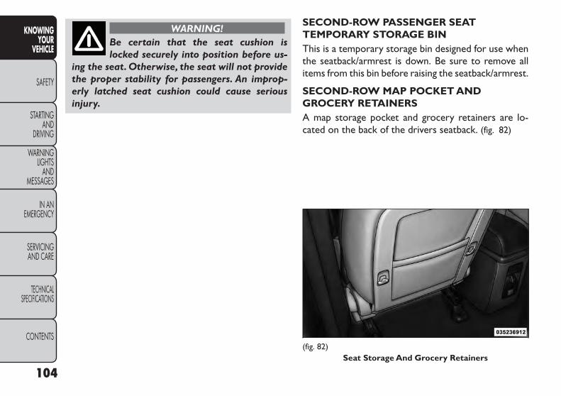
WARNING!Be certain that the seat cushion islocked securely into position before us-
ing the seat. Otherwise, the seat will not providethe proper stability for passengers. An improp-erly latched seat cushion could cause seriousinjury.
SECOND-ROW PASSENGER SEATTEMPORARY STORAGE BINThis is a temporary storage bin designed for use whenthe seatback/armrest is down. Be sure to remove allitems from this bin before raising the seatback/armrest.
SECOND-ROW MAP POCKET ANDGROCERY RETAINERSA map storage pocket and grocery retainers are lo-cated on the back of the drivers seatback. (fig. 82)
(fig. 82)Seat Storage And Grocery Retainers
104
KNOWINGYOUR
VEHICLE
SAFETY
STARTINGAND
DRIVING
WARNINGLIGHTS
ANDMESSAGES
IN ANEMERGENCY
SERVICINGAND CARE
TECHNICALSPECIFICATIONS
CONTENTS

IN-FLOOR STORAGE BIN WITHREMOVABLE LINER
NOTE: Position the front seat to at least a mid-trackposition to provide easier access to the storage bin.An in-floor storage bin is located behind each frontseat. Each 5.9 l bin can hold up to 12, 0.35 l cans, plusice, or other items. The removable bin liner allows foreasy filling, emptying, and cleaning.
To access the bin, position the floor mat aside (forversions/markets, where provided). Pull the door latchrelease-loop upward to release the latch and thenforward to open the bin door. (fig. 83)
The liner can be removed for easy cleaning by lifting onthe notches as shown. (fig. 84)
(fig. 83)In-Floor Storage
(fig. 84)Removable Liner
105
KNOWINGYOURVEHICLE
SAFETY
STARTINGANDDRIVING
WARNINGLIGHTSANDMESSAGES
IN ANEMERGENCY
SERVICINGAND CARE
TECHNICALSPECIFICATIONS
CONTENTS

ELECTRICAL POWER OUTLETSA 12 Volt (13 Amp) power outlet is located in thecenter console below the radio. The power outlet haspower available when the ignition switch in the ON/RUN or ACC position. (fig. 85)
This power outlet will also operate a conventional cigarlighter unit. To preserve the heating element, donot hold the lighter in the heating position.
A second 12 Volt (13 Amp) power outlet is locatedinside the center console storage area. Power is avail-able with the ignition switch in the ON/RUN, ACC orLOCK position. (fig. 86)
(fig. 85)Front 12Volt Power Outlet
(fig. 86)Center Console 12Volt Power Outlet
106
KNOWINGYOUR
VEHICLE
SAFETY
STARTINGAND
DRIVING
WARNINGLIGHTS
ANDMESSAGES
IN ANEMERGENCY
SERVICINGAND CARE
TECHNICALSPECIFICATIONS
CONTENTS

A third fused 12 Volt power outlet is located on theback of the center console. This power outlet haspower available when the ignition switch is in theLOCK, ON or ACC position. (fig. 87)
A fourth fused 12 Volt power outlet is located on theleft quarter trim panel in the cargo area. This poweroutlet has power available when the ignition switch is inthe ON or ACC position. (fig. 88)
(fig. 87)Rear Seat 12Volt Power Outlet
(fig. 88)Rear Cargo Area Power Outlet
107
KNOWINGYOURVEHICLE
SAFETY
STARTINGANDDRIVING
WARNINGLIGHTSANDMESSAGES
IN ANEMERGENCY
SERVICINGAND CARE
TECHNICALSPECIFICATIONS
CONTENTS

• Do not exceed the maximum powerof 160Watts (13 Amps) at 12Volts. If the160 Watt (13 Amp) power rating is ex-
ceeded the fuse protecting the system will need tobe replaced.• The power outlet on the bottom of the centerconsole shares the fuse with the power outlet onthe back of the console.The combined usage mustnot exceed 160Watts (13 Amps) at 12Volts.• Power outlets are designed for accessory plugsonly. Do not insert any other object in the poweroutlets as this will damage the outlet and blowthe fuse. Improper use of the power outlet cancause damage not covered by your New VehicleLimitedWarranty.
(fig. 89)
WARNING!To avoid serious injury or death:• Only devices designed for use in this
type of outlet should be inserted into any 12Voltoutlet.• Do not touch with wet hands.• Close the lid when not in use and while drivingthe vehicle.• If this outlet is mishandled, it may cause anelectric shock and failure.
(fig. 89)
1 — F103 20 A Yellow Power Outlet Console Bin & PowerOutlet Console Rear2 — F102 20 A Yellow Cigar Lighter Instrument Panel &Power Outlet Left Rear Cargo Area
108
KNOWINGYOUR
VEHICLE
SAFETY
STARTINGAND
DRIVING
WARNINGLIGHTS
ANDMESSAGES
IN ANEMERGENCY
SERVICINGAND CARE
TECHNICALSPECIFICATIONS
CONTENTS

• Many accessories that can be plugged indraw power from the vehicle's battery,even when not in use (i.e., cellular phones,
etc.). Eventually, if plugged in long enough, thevehicle's battery will discharge sufficiently to de-grade battery life and/or prevent the engine fromstarting.• Accessories that draw higher power (i.e., cool-ers, vacuum cleaners, lights, etc.) will degrade thebattery even more quickly. Only use these inter-mittently and with greater caution.• After the use of high power draw accessories,orlong periods of the vehicle not being started (withaccessories still plugged in), the vehicle must bedriven a sufficient length of time to allow thealternator to recharge the vehicle's battery.• Power outlets are designed for accessory plugsonly. Do not hang any type of accessory or acces-sory bracket from the plug.
CUPHOLDERSThere are two cupholders, located in the center floorconsole, for the front passengers. (fig. 90)
For passengers in the second row there are two cup-holders, located in the center armrest between thetwo seats.
(fig. 90)Floor Console Cupholders
109
KNOWINGYOURVEHICLE
SAFETY
STARTINGANDDRIVING
WARNINGLIGHTSANDMESSAGES
IN ANEMERGENCY
SERVICINGAND CARE
TECHNICALSPECIFICATIONS
CONTENTS

When the armrest is folded flat the cupholders are inthe back of the Head Restraint. The Head Restraint canbe adjusted to better position the cupholders. (fig. 91)
For vehicles equipped with third row seating, there areadditional cupholders located in the trim panels.
In addition to cupholders, vehicles may also beequipped with bottle holders. The bottle holders arelocated on the door trim panels. (fig. 92)
WARNING!If containers of hot liquid are placed inthe bottle holder,they can spill when the
door is closed, burning the occupants. Be carefulwhen closing the doors to avoid injury.
(fig. 91)Armrest Cupholders
(fig. 92)Door Bottle Holder
110
KNOWINGYOUR
VEHICLE
SAFETY
STARTINGAND
DRIVING
WARNINGLIGHTS
ANDMESSAGES
IN ANEMERGENCY
SERVICINGAND CARE
TECHNICALSPECIFICATIONS
CONTENTS

POWER SUNROOF (for versions/markets, where provided)The power sunroof switch is located between the sunvisors on the overhead console. (fig. 93)
WARNING!• Never leave children unattended in avehicle, and do not leave the key fob in
or near the vehicle, or in a location accessible tochildren. Do not leave the ignition of a vehicleequipped with Keyless Enter-N-Go™ in the ACCor ON/Run mode. Occupants, particularly unat-tended children, can become entrapped by thepower sunroof while operating the power sun-roof switch. Such entrapment may result in seri-ous injury or death.• In a collision, there is a greater risk of beingthrown from a vehicle with an open sunroof.Youcould also be seriously injured or killed. Alwaysfasten your seat belt properly and make sure allpassengers are also properly secured.• Do not allow small children to operate thesunroof. Never allow your fingers, other bodyparts, or any object, to project through the sun-roof opening. Injury may result.
OPENING SUNROOF — EXPRESSPress the switch rearward and release it within one-halfsecond and the sunroof will open automatically fromany position. The sunroof will open fully and stopautomatically. This is called “Express Open”. DuringExpress Open operation, any movement of the sunroofswitch will stop the sunroof.
(fig. 93)Power Sunroof Switch
111
KNOWINGYOURVEHICLE
SAFETY
STARTINGANDDRIVING
WARNINGLIGHTSANDMESSAGES
IN ANEMERGENCY
SERVICINGAND CARE
TECHNICALSPECIFICATIONS
CONTENTS
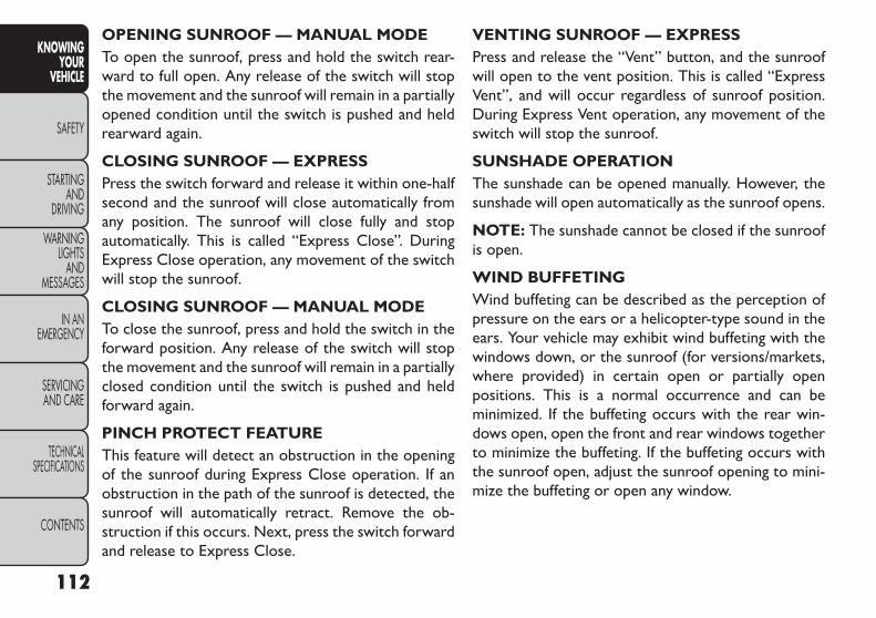
OPENING SUNROOF — MANUAL MODETo open the sunroof, press and hold the switch rear-ward to full open. Any release of the switch will stopthe movement and the sunroof will remain in a partiallyopened condition until the switch is pushed and heldrearward again.
CLOSING SUNROOF — EXPRESSPress the switch forward and release it within one-halfsecond and the sunroof will close automatically fromany position. The sunroof will close fully and stopautomatically. This is called “Express Close”. DuringExpress Close operation, any movement of the switchwill stop the sunroof.
CLOSING SUNROOF — MANUAL MODETo close the sunroof, press and hold the switch in theforward position. Any release of the switch will stopthe movement and the sunroof will remain in a partiallyclosed condition until the switch is pushed and heldforward again.
PINCH PROTECT FEATUREThis feature will detect an obstruction in the openingof the sunroof during Express Close operation. If anobstruction in the path of the sunroof is detected, thesunroof will automatically retract. Remove the ob-struction if this occurs. Next, press the switch forwardand release to Express Close.
VENTING SUNROOF — EXPRESSPress and release the “Vent” button, and the sunroofwill open to the vent position. This is called “ExpressVent”, and will occur regardless of sunroof position.During Express Vent operation, any movement of theswitch will stop the sunroof.
SUNSHADE OPERATIONThe sunshade can be opened manually. However, thesunshade will open automatically as the sunroof opens.
NOTE: The sunshade cannot be closed if the sunroofis open.
WIND BUFFETINGWind buffeting can be described as the perception ofpressure on the ears or a helicopter-type sound in theears. Your vehicle may exhibit wind buffeting with thewindows down, or the sunroof (for versions/markets,where provided) in certain open or partially openpositions. This is a normal occurrence and can beminimized. If the buffeting occurs with the rear win-dows open, open the front and rear windows togetherto minimize the buffeting. If the buffeting occurs withthe sunroof open, adjust the sunroof opening to mini-mize the buffeting or open any window.
112
KNOWINGYOUR
VEHICLE
SAFETY
STARTINGAND
DRIVING
WARNINGLIGHTS
ANDMESSAGES
IN ANEMERGENCY
SERVICINGAND CARE
TECHNICALSPECIFICATIONS
CONTENTS

SUNROOF MAINTENANCEUse only a nonabrasive cleaner and a soft cloth to cleanthe glass panel.
IGNITION OFF OPERATIONFor versions/markets, where provided withoutthe ElectronicVehicle Information Center (EVIC)
The power sunroof switch will remain active for 45 sec-onds after the ignition switch is turned to the LOCKposition. Opening either front door will cancel thisfeature.
For versions/markets, where provided with theEVIC
The power sunroof switch will remain active for up to10 minutes after the ignition switch is turned to theLOCK position. Opening either front door will cancelthis feature.
NOTE: The delay time is programmable using theUconnect® system. Refer to “Uconnect® Settings” forfurther information.
DOOR LOCKSMANUAL DOOR LOCKSTo lock each door, push the door lock knob on eachdoor trim panel downward. To unlock the front doors,pull the inside door handle to the first detent. Tounlock the rear doors, pull the door lock knob on thedoor trim panel upward. (fig. 94)
If the door lock knob is down when you shut the door,the door will lock. Therefore, make sure the Key Fob isnot inside the vehicle before closing the door.
NOTE: The manual door locks will not lock or unlockthe liftgate.
(fig. 94)Manual Door Lock Knob
113
KNOWINGYOURVEHICLE
SAFETY
STARTINGANDDRIVING
WARNINGLIGHTSANDMESSAGES
IN ANEMERGENCY
SERVICINGAND CARE
TECHNICALSPECIFICATIONS
CONTENTS

WARNING!• For personal security and safety in theevent of a collision, lock the vehicle
doors before you drive as well as when you parkand leave the vehicle.• When leaving the vehicle, always remove theKey Fob from the vehicle and lock your vehicle.Unsupervised use of vehicle equipment maycause severe personal injuries or death.• Never leave children alone in a vehicle, or withaccess to an unlocked vehicle. Allowing childrento be in a vehicle unattended is dangerous for anumber of reasons. A child or others could beseriously or fatally injured. Children should bewarned not to touch the parking brake, brakepedal or the shift lever.• Do not leave the Key Fob in or near the vehicle,or in a location accessible to children,and do notleave the ignition of a vehicle equipped withKeyless Enter-N-Go™ in the ACC or ON/RUNmode. A child could operate power windows,other controls, or move the vehicle.
POWER DOOR LOCKSA power door lock switch is on each front door trimpanel. Use this switch to lock or unlock the doors andliftgate. (fig. 95)
If you press the power door lock switch while theignition is in the ACC or ON/RUN position, and anyfront door is open, the power locks will not operate.This prevents you from accidentally locking the KeyFob in the vehicle. Cycling the ignition to the OFFposition or closing the door will allow the locks tooperate. If a door is open, and the ignition is in theACC or ON/RUN position, a chime will sound as areminder to turn the ignition OFF.
(fig. 95)Power Door Lock Switch Location
114
KNOWINGYOUR
VEHICLE
SAFETY
STARTINGAND
DRIVING
WARNINGLIGHTS
ANDMESSAGES
IN ANEMERGENCY
SERVICINGAND CARE
TECHNICALSPECIFICATIONS
CONTENTS

Automatic Door LocksThe auto door lock feature default condition is dis-abled. When enabled, the door locks will lock auto-matically when the vehicle's speed exceeds 24 km/h.The auto door lock feature can be enabled or disabledby your authorized dealer per written request of thecustomer. Please see your authorized dealer for ser-vice.
Automatic Unlock Doors On ExitThe doors will unlock automatically on vehicles withpower door locks if:
1. The Automatic Unlock Doors On Exit feature isenabled.
2. The vehicle was in motion, then speed returned to0 km/h and the transmission shift lever is placed inNEUTRAL or PARK.
3. The driver door is opened.
4. The doors were not previously unlocked.
To change the current setting, refer to “Uconnect®Settings” in “Knowing Your Vehicle” for further infor-mation.
NOTE: Use the Automatic Unlock Doors On Exitfeature in accordance with local laws.
Automatic Unlock Doors On ExitProgrammingThe Automatic Unlock Doors On Exit feature can beenabled or disabled as follows:
• For vehicles equipped with the Uconnect®, refer to“Uconnect® Settings” in “Knowing Your Vehicle” forfurther information.
NOTE: Use the Automatic Unlock Doors On Exitfeature in accordance with local laws.
115
KNOWINGYOURVEHICLE
SAFETY
STARTINGANDDRIVING
WARNINGLIGHTSANDMESSAGES
IN ANEMERGENCY
SERVICINGAND CARE
TECHNICALSPECIFICATIONS
CONTENTS

CHILD-PROTECTION DOOR LOCKSYSTEM — REAR DOORSTo provide a safer environment for small children ridingin the rear seats, the rear doors are equipped with aChild-Protection Door Lock system.
To EngageThe Child-Protection Door LockSystem
1. Open the rear door.
2. Insert the tip of the emergency key (or alike) intothe child lock control and rotate it to the LOCKposition. (fig. 96) (fig. 97)
3. Repeat Steps 1 and 2 for the opposite rear door.
NOTE: When the Child-Protection Door Lock sys-tem is engaged, the door can be opened only by usingthe outside door handle even though the inside doorlock is in the unlocked position.
WARNING!Avoid trapping anyone in a vehicle in acollision. Remember that the rear doors
can only be opened from the outside when theChild-Protection locks are engaged. Failure tofollow this warning may result in serious injury ordeath.
(fig. 96)Child-Protection Door Lock Location
(fig. 97)Child-Protection Door Lock Function
116
KNOWINGYOUR
VEHICLE
SAFETY
STARTINGAND
DRIVING
WARNINGLIGHTS
ANDMESSAGES
IN ANEMERGENCY
SERVICINGAND CARE
TECHNICALSPECIFICATIONS
CONTENTS

NOTE:
• After engaging the Child-Protection Door Lock sys-tem, always test the door from the inside to makecertain it is in the desired position.
• For emergency exit with the system engaged, movethe lock knob up to the UNLOCK position, rolldown the window, and open the door with theoutside door handle.
To DisengageThe Child-Protection Door LockSystem
1. Open the rear door.
2. Insert the tip of the emergency key (or alike) intothe child lock control and rotate it to the UNLOCKposition. (fig. 98)
3. Repeat Steps 1 and 2 for the opposite rear door.
NOTE: After disengaging the Child-Protection DoorLock system, always test the door from the inside tomake certain it is in the desired position.
(fig. 98)Child-Protection Door Lock Function
117
KNOWINGYOURVEHICLE
SAFETY
STARTINGANDDRIVING
WARNINGLIGHTSANDMESSAGES
IN ANEMERGENCY
SERVICINGAND CARE
TECHNICALSPECIFICATIONS
CONTENTS

KEYLESS ENTER-N-GO™The Passive Entry system is an enhancement to thevehicle’s Remote Keyless Entry (RKE) system and afeature of Keyless Enter-N-Go™. This feature allowsyou to lock and unlock the vehicle’s door(s) withouthaving to press the RKE transmitter lock or unlockbuttons.
NOTE:
• Passive Entry may be programmed ON/OFF; refer to“Uconnect® Settings” in “Knowing Your Vehicle” forfurther information.
• If wearing gloves on your hands, or if it has beenraining on the Passive Entry door handle, the unlocksensitivity can be affected, resulting in a slower re-sponse time.
• If the vehicle is unlocked by the RKE transmitter orPassive Entry and no door goes ajar within 60 sec-onds, the vehicle will re-lock and will arm the theftalarm.
To Unlock FromThe Driver's Side:
With a valid Passive Entry RKE transmitter within1.5 m of the driver's door handle, grab the driver'sfront door handle to unlock the driver's door auto-matically. The interior door panel lock knob will raisewhen the door is unlocked. (fig. 99)
NOTE: If “Unlock All Doors 1st Press” is pro-grammed all doors will unlock when you grab hold ofthe driver’s front door handle. To select between“Unlock Driver Door 1st Press” and “Unlock AllDoors 1st Press”, refer to “Electronic Vehicle Informa-tion Center (EVIC)/Personal Settings (Customer-Programmable Features)” in “Knowing Your Vehicle”for further information.
(fig. 99)GrabbingThe Driver's Door Handle
118
KNOWINGYOUR
VEHICLE
SAFETY
STARTINGAND
DRIVING
WARNINGLIGHTS
ANDMESSAGES
IN ANEMERGENCY
SERVICINGAND CARE
TECHNICALSPECIFICATIONS
CONTENTS

To Unlock FromThe Passenger Side:
With a valid Passive Entry RKE transmitter within1.5 m of the passenger door handle, grab the frontpassenger door handle to unlock all four doors and theliftgate automatically.
NOTE: All doors and the liftgate will unlock when thefront passenger door handle is grabbed regardless ofthe driver’s door unlock preference setting (“UnlockDriver Door 1st Press” or “Unlock All Doors 1stPress”).
To EnterThe Liftgate
With a valid Passive Entry RKE transmitter within1.0 m of the liftgate, press the button underneath theleft side of the accent bar, which is located on theliftgate below the glass, to lock or unlock the vehicle.(fig. 100)
(fig. 100)Liftgate Unlock/Lock Button
119
KNOWINGYOURVEHICLE
SAFETY
STARTINGANDDRIVING
WARNINGLIGHTSANDMESSAGES
IN ANEMERGENCY
SERVICINGAND CARE
TECHNICALSPECIFICATIONS
CONTENTS

Preventing Inadvertent Locking Of PassiveEntry RKETransmitter InVehicle
To minimize the possibility of unintentionally locking aPassive Entry RKE transmitter inside your vehicle, thePassive Entry system is equipped with an automaticdoor unlock feature which will function if the ignitionswitch is in the OFF position.
If one of the vehicle doors is open and the door panelswitch is used to lock the vehicle, once all open doorshave been closed the vehicle checks the inside andoutside of the vehicle for any valid Passive Entry RKEtransmitters. If one of the vehicle's Passive Entry RKEtransmitters is detected inside the vehicle, and noother valid Passive Entry RKE transmitters are de-tected outside the vehicle, the Passive Entry Systemautomatically unlocks all vehicle doors and chirps thehorn three times (on the third attempt ALL doors willlock and the Passive Entry RKE transmitter can belocked in the vehicle).
To LockTheVehicle’s Doors
With one of the vehicle’s Passive Entry RKE transmit-ters within 1.5 m of the driver or passenger front doorhandle, press the door handle LOCK button to lock allfour doors and liftgate. (fig. 101)
(fig. 101)Outside Door Handle Lock Button
120
KNOWINGYOUR
VEHICLE
SAFETY
STARTINGAND
DRIVING
WARNINGLIGHTS
ANDMESSAGES
IN ANEMERGENCY
SERVICINGAND CARE
TECHNICALSPECIFICATIONS
CONTENTS

Do NOT grab the door handle, when pressing the doorhandle lock button. This could unlock the door(s).(fig. 102)
NOTE:
• After pressing the door handle LOCK button, youmust wait two seconds before you can lock or unlockthe doors, using either Passive Entry door handle.This is done to allow you to check if the vehicle islocked by pulling the door handle, without the ve-hicle reacting and unlocking.
• If Passive Entry is disabled using Uconnect® System,the key protection described in "Preventing Inadver-tent Locking of Passive Entry RKE Transmitter inVehicle" remains active/functional.
• The Passive Entry system will not operate if the RKEtransmitter battery is dead.
The vehicle doors can also be locked by using the RKEtransmitter lock button or the lock button located onthe vehicle’s interior door panel.
(fig. 102)Do NOT GrabThe Door Handle When Locking
121
KNOWINGYOURVEHICLE
SAFETY
STARTINGANDDRIVING
WARNINGLIGHTSANDMESSAGES
IN ANEMERGENCY
SERVICINGAND CARE
TECHNICALSPECIFICATIONS
CONTENTS
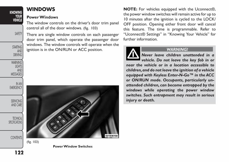
WINDOWSPower WindowsThe window controls on the driver's door trim panelcontrol all of the door windows. (fig. 103)
There are single window controls on each passengerdoor trim panel, which operate the passenger doorwindows. The window controls will operate when theignition is in the ON/RUN or ACC position.
NOTE: For vehicles equipped with the Uconnect®,the power window switches will remain active for up to10 minutes after the ignition is cycled to the LOCK/OFF position. Opening either front door will cancelthis feature. The time is programmable. Refer to“Uconnect® Settings” in “Knowing Your Vehicle” forfurther information.
WARNING!Never leave children unattended in avehicle. Do not leave the key fob in or
near the vehicle or in a location accessible tochildren,and do not leave the ignition of a vehicleequipped with Keyless Enter-N-Go™ in the ACCor ON/RUN mode. Occupants, particularly un-attended children, can become entrapped by thewindows while operating the power windowswitches. Such entrapment may result in seriousinjury or death.
(fig. 103)Power Window Switches
122
KNOWINGYOUR
VEHICLE
SAFETY
STARTINGAND
DRIVING
WARNINGLIGHTS
ANDMESSAGES
IN ANEMERGENCY
SERVICINGAND CARE
TECHNICALSPECIFICATIONS
CONTENTS

Auto-Down FeatureThe driver's power window switch has an Auto-downfeature. Press the window switch past the first detent,release, and the window will go down automatically.
To open the window part way, press the windowswitch to the first detent and release it when you wantthe window to stop.
To stop the window from going all the way down duringthe Auto-down operation, pull up on the switch briefly.
Auto-Up Feature With Anti-Pinch ProtectionOn some models, the driver and front passengerpower window switches have an Auto-up feature. Pullthe window switch up to the second detent, release,and the window will go up automatically.
To stop the window from going all the way up duringthe Auto-up operation, push down on the switchbriefly.
To close the window part way, pull the window switchup to the first detent and release it when you want thewindow to stop.
NOTE:
• If the window runs into any obstacle during Auto-closure, it will reverse direction and then go backdown. Remove the obstacle and use the windowswitch again to close the window.
• Any impact due to rough road conditions may triggerthe auto-reverse function unexpectedly during auto-closure. If this happens, pull the switch lightly to thefirst detent and hold to close window manually.
WARNING!There is no anti-pinch protection whenthe window is almost closed. To avoid
personal injury,be sure to clear your arms,hands,fingers,and objects from the window path beforeclosing the window. Such entrapment may resultin serious injury.
ResetIt may be necessary at some point in time to reactivatethe Auto-up/Auto-down feature. To do so, performthe following steps:
1. Pull the window switch up to close the windowcompletely and continue to hold the switch up foran additional two seconds after the window isclosed.
2. Push the window switch down firmly to the seconddetent to open the window completely and con-tinue to hold the switch down for an additional twoseconds after the window is fully open.
123
KNOWINGYOURVEHICLE
SAFETY
STARTINGANDDRIVING
WARNINGLIGHTSANDMESSAGES
IN ANEMERGENCY
SERVICINGAND CARE
TECHNICALSPECIFICATIONS
CONTENTS

Window Lockout SwitchThe window lockout switch on the driver's door trimpanel allows you to disable the window control on therear doors. To disable the window controls, press andrelease the window lockout button (setting it in thedown position). To enable the window controls, pressand release the window lockout button again (setting itin the up position). (fig. 104)
WIND BUFFETINGWind buffeting can be described as the perception ofpressure on the ears or a helicopter-type sound in theears. Your vehicle may exhibit wind buffeting with thewindows down, or the sunroof (for versions/markets,where provided) in certain open or partially openpositions. This is a normal occurrence and can beminimized. If the buffeting occurs with the rear win-dows open, then open the front and rear windowstogether to minimize the buffeting. If the buffetingoccurs with the sunroof open, adjust the sunroofopening to minimize the buffeting or open any window.
(fig. 104)Window Lockout Switch
124
KNOWINGYOUR
VEHICLE
SAFETY
STARTINGAND
DRIVING
WARNINGLIGHTS
ANDMESSAGES
IN ANEMERGENCY
SERVICINGAND CARE
TECHNICALSPECIFICATIONS
CONTENTS

LIFTGATEThe liftgate can be unlocked or locked with the Re-mote Keyless Entry (RKE) transmitter, the KeylessEnter-N-Go™ (Passive Entry) or by activating thepower door lock switch located on either front doortrim panel.
For further information on Keyless Enter-N-Go™(Passive Entry), refer to “Keyless Enter-N-Go™” in“Starting And Driving”.
NOTE: The liftgate cannot be unlocked or locked withthe manual door lock plungers on the door trim panelsor the door lock cylinder on the driver's door.
To open the unlocked liftgate, squeeze the handle andpull the liftgate toward you. Gas props will raise andsupport the liftgate in the open position. (fig. 105)
NOTE: Because the gas pressure drops with tempera-ture, it may be necessary to assist the props whenopening the liftgate in cold weather.
WARNING!• Driving with the liftgate open can al-low poisonous exhaust gases into your
vehicle. These fumes could injure you and yourpassengers.Keep the liftgate closed when you areoperating the vehicle.• If you are required to drive with the liftgateopen,make sure that all windows are closed,andthe blower switch on the climate control is set athigh speed. Do not use the recirculation mode.
(fig. 105)Liftgate Unlock/Lock Button
125
KNOWINGYOURVEHICLE
SAFETY
STARTINGANDDRIVING
WARNINGLIGHTSANDMESSAGES
IN ANEMERGENCY
SERVICINGAND CARE
TECHNICALSPECIFICATIONS
CONTENTS
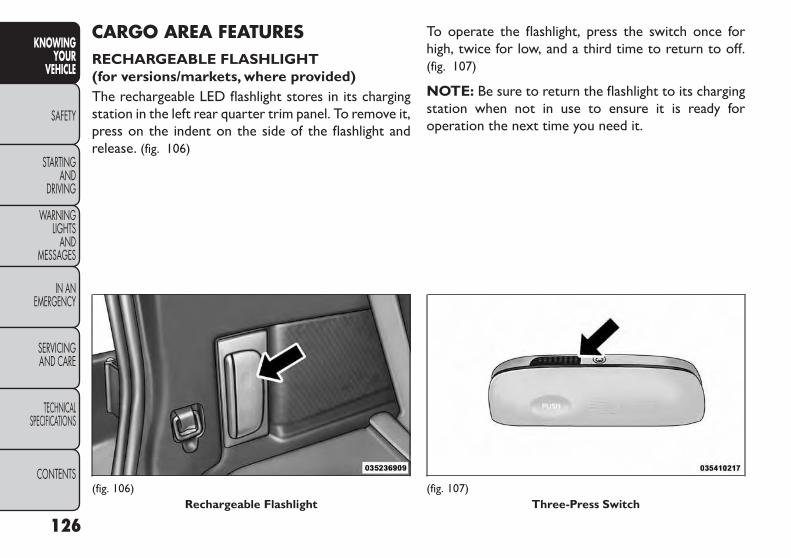
CARGO AREA FEATURESRECHARGEABLE FLASHLIGHT(for versions/markets, where provided)The rechargeable LED flashlight stores in its chargingstation in the left rear quarter trim panel. To remove it,press on the indent on the side of the flashlight andrelease. (fig. 106)
To operate the flashlight, press the switch once forhigh, twice for low, and a third time to return to off.(fig. 107)
NOTE: Be sure to return the flashlight to its chargingstation when not in use to ensure it is ready foroperation the next time you need it.
(fig. 106)Rechargeable Flashlight
(fig. 107)Three-Press Switch
126
KNOWINGYOUR
VEHICLE
SAFETY
STARTINGAND
DRIVING
WARNINGLIGHTS
ANDMESSAGES
IN ANEMERGENCY
SERVICINGAND CARE
TECHNICALSPECIFICATIONS
CONTENTS
CARGO MANAGEMENT SYSTEM
FIVE PASSENGER SYSTEM FEATURES
• A raised load floor that sits on top of a large built-instorage bin.
• A tri-fold door built into the load floor that allowseasy access to items in the built-in storage bin.
• 60/40 split second-row passenger seats with fold flatfeature, which allows for extended cargo space. Re-fer to “Seats” for further information.
• An optional front passenger seat with fold flat fea-ture, which extends cargo space even further. Referto “Seats” for further information.
• Cargo tie-downs.
• A retractable cargo area cover (for versions/markets,where provided).
SEVEN PASSENGER SYSTEM FEATURES
• A large built-in storage bin with a hinged hardcoverlocated in the floor behind the third-row passengerseats.
• 60/40 split second-row passenger seats with fold flatfeature, which allows for extended cargo space. Re-fer to “Seats” in “Knowing your vehicle” for furtherinformation.
• 50/50 split third-row passenger seats with fold flatfeature, which allows for extended cargo space. Re-fer to “Seats” for further information.
• An optional front passenger seat with fold flat fea-ture, which extends cargo space even further. Referto “Seats” for further information.
• Cargo tie-downs.
127
KNOWINGYOURVEHICLE
SAFETY
STARTINGANDDRIVING
WARNINGLIGHTSANDMESSAGES
IN ANEMERGENCY
SERVICINGAND CARE
TECHNICALSPECIFICATIONS
CONTENTS

CARGOTIE-DOWNS
WARNING!Cargo tie-downs are not safe anchors fora child seat tether strap.In a sudden stop
or collision,a tie-down could pull loose and allowthe child seat to come loose. A child could bebadly injured. Use only the anchors provided forchild seat tethers.
Cargo tie-downs are located on both rear trim panels.These tie-downs should be used to secure loads safelywhen the vehicle is moving. (fig. 108)
WARNING!The weight and position of cargo andpassengers can change the vehicle cen-
ter of gravity and vehicle handling.To avoid loss ofcontrol resulting in personal injury, follow theseguidelines for loading your vehicle:
• Do not carry loads that exceed the load limits de-scribed on the label attached to the left door or leftdoor center pillar.
• Always place cargo evenly on the cargo floor. Putheavier objects as low and as far forward as possible.
• Place as much cargo as possible in front of the rearaxle. Too much weight or improperly placed weightover or behind the rear axle can cause the vehicle tosway.
• Do not pile luggage or cargo higher than the top ofthe seatback. This could impair visibility or become adangerous projectile in a sudden stop or collision.
• To help protect against personal injury, passengersshould not be seated in the rear cargo area. The rearcargo space is intended for load carrying purposesonly, not for passengers, who should sit in seats anduse seat belts.
(fig. 108)CargoTie-Downs
128
KNOWINGYOUR
VEHICLE
SAFETY
STARTINGAND
DRIVING
WARNINGLIGHTS
ANDMESSAGES
IN ANEMERGENCY
SERVICINGAND CARE
TECHNICALSPECIFICATIONS
CONTENTS

RETRACTABLE CARGO AREA COVER(for versions/markets, where provided) —FIVE PASSENGER MODELS
NOTE: The purpose of this cover is for privacy, not tosecure loads. It will not prevent cargo from shifting orprotect passengers from loose cargo.The removable retractable cargo area cover mounts inthe cargo area behind the top of the rear seats.
The cover, when extended, covers the cargo area tokeep items out of sight. Notches in the trim panels nearthe liftgate opening secure the extended cover in place.
The cover rolls away neatly inside its housing when notin use. You can also remove the cover from the vehicleto make more room in the cargo area.
To install the cover, position it in the vehicle so that theflat side of the housing faces upward. Then, inserteither the left or the right spring-loaded post (locatedon the ends of the cover housing) into the left attach-ment point or the right attachment point (shown).(fig. 109)
(fig. 109)Installing Retractable Cargo Area Cover
129
KNOWINGYOURVEHICLE
SAFETY
STARTINGANDDRIVING
WARNINGLIGHTSANDMESSAGES
IN ANEMERGENCY
SERVICINGAND CARE
TECHNICALSPECIFICATIONS
CONTENTS

Insert the spring-loaded post on the opposite end ofthe cover housing into the attachment point on theopposite side of the vehicle.
Grab the cover handle and pull it toward you. As thecover nears the liftgate opening, guide the rear attach-ment posts (on both ends of the cover) into thenotches in the trim panels. Lower the cover to positionthe posts into the bottom of the notches and releasethe handle. (fig. 110)
WARNING!A cargo cover that is unsecured in thevehicle could cause injury in a collision.It
could become airborne during a sudden stop andstrike someone inside the vehicle. Do not storethe cargo cover on the cargo floor or in thepassenger compartment. Remove the cover fromthe vehicle when taken from its mounting.Do notstore it in the vehicle.
(fig. 110)Positioning Retractable Cargo Area Cover
130
KNOWINGYOUR
VEHICLE
SAFETY
STARTINGAND
DRIVING
WARNINGLIGHTS
ANDMESSAGES
IN ANEMERGENCY
SERVICINGAND CARE
TECHNICALSPECIFICATIONS
CONTENTS

TO OPEN AND CLOSE THE HOODTwo latches must be released to open the hood.
1. Pull the hood release lever located under the leftside of the instrument panel. (fig. 111)
2. Outside of the vehicle, locate the safety latch levernear the center of the grille between the grille andhood opening. Push the safety latch lever to theright and then raise the hood. (fig. 112)
Use the hood prop rod to secure the hood in the openposition. Place the upper end of the prop rod in thehole on the underside of the hood. (fig. 113)
(fig. 111)Hood Release Lever
(fig. 112)Underhood Safety Latch
(fig. 113)Hood Prop Rod
131
KNOWINGYOURVEHICLE
SAFETY
STARTINGANDDRIVING
WARNINGLIGHTSANDMESSAGES
IN ANEMERGENCY
SERVICINGAND CARE
TECHNICALSPECIFICATIONS
CONTENTS

To prevent possible damage:• Before closing hood, make sure thehood prop rod is fully seated into its
storage retaining clips.• Do not slam the hood to close it. Use a firmdownward push at the center front edge of thehood to ensure that both latches engage. Neverdrive your vehicle unless the hood is fully closed,with both latches engaged.
WARNING!Be sure the hood is fully latched beforedriving your vehicle. If the hood is not
fully latched, it could open when the vehicle is inmotion and block your vision. Failure to followthis warning could result in serious injury ordeath.
ROOF LUGGAGE RACK(for versions/markets, whereprovided)The roof rack side rails on your vehicle are NOTdesigned to carry a load without the addition of cross-bars. Metal Crossbars can be purchased from yourFIAT dealer to provide a functional roof rack system.
External racks do not increase the total load carryingcapacity of the vehicle. Be sure that the total occupantand luggage load inside the vehicle plus the load on theluggage rack do not exceed the maximum vehicle loadcapacity.
The roof rack cross rails and side rails together aredesigned to carry cargo weight. The load must notexceed 150 pounds or 68 kg, and it should be distrib-uted uniformly over the cross rails.
WARNING!Cargo must be securely tied before driv-ing your vehicle. Improperly secured
loads can fly off the vehicle, particularly at highspeeds, resulting in personal injury or propertydamage. Follow the roof rack cautions whencarrying cargo on your roof rack.
132
KNOWINGYOUR
VEHICLE
SAFETY
STARTINGAND
DRIVING
WARNINGLIGHTS
ANDMESSAGES
IN ANEMERGENCY
SERVICINGAND CARE
TECHNICALSPECIFICATIONS
CONTENTS

• To prevent damage to the roof of yourvehicle, DO NOT carry any loads on theroof rack without the crossbars installed.
The load should be secured and placed on top ofthe crossbars, not directly on the roof. If it isnecessary to place the load on the roof, place ablanket or other protective layer between theload and the roof surface.• To avoid damage to the roof rack and vehicle,do not exceed the maximum roof rack load ca-pacity of 68 kg.Always distribute heavy loads asevenly as possible and secure the load appropri-ately.• Long loads, which extend over the windshield,such as wood panels or surfboards, should besecured to both the front and rear of the vehicle.• Travel at reduced speeds and turn corners care-fully when carrying large or heavy loads on theroof rack.Wind forces, due to natural causes ornearby truck traffic, can add sudden upwardloads.This is especially true on large flat loads andmay result in damage to the cargo or your vehicle.
BRAKE SYSTEM
Your vehicle is equipped with dual hydraulicbrake systems. If either of the two hydraulic
systems loses normal capability, the remaining systemwill still function. However, there will be some loss ofoverall braking effectiveness. This will be evident byincreased pedal travel during application and greaterpedal force required to slow or stop the vehicle. Inaddition, if the malfunction is caused by a leak in thehydraulic system, the “Brake System Warning Light”will turn on as the brake fluid level drops in the mastercylinder.
In the event power assist is lost for any reason (i.e.,repeated brake applications with the engine OFF) thebrakes will still function. However, the effort requiredto brake the vehicle will be much greater than thatrequired with the power system operating.
133
KNOWINGYOURVEHICLE
SAFETY
STARTINGANDDRIVING
WARNINGLIGHTSANDMESSAGES
IN ANEMERGENCY
SERVICINGAND CARE
TECHNICALSPECIFICATIONS
CONTENTS

WARNING!• Riding the brakes can lead to brakefailure and possibly a collision. Driving
with your foot resting or riding on the brakepedal can result in abnormally high brake tem-peratures, excessive lining wear, and possiblebrake damage.You would not have your full brak-ing capacity in an emergency.• Driving a vehicle with the “Brake WarningLight” on is dangerous. A significant decrease inbraking performance or vehicle stability duringbraking may occur. It will take you longer to stopthe vehicle or will make your vehicle harder tocontrol.You could have a collision. Have the ve-hicle checked immediately.
ANTI-LOCK BRAKE SYSTEM (ABS)This system aids the driver in maintaining vehicle con-trol under adverse braking conditions. The systemcontrols hydraulic brake pressure to prevent wheellock-up to help avoid skidding on slippery surfacesduring braking. Refer to “Anti-Lock Brake System(ABS)” under “Knowing Your Vehicle/Electronic BrakeControl System” for further information.
WARNING!TheABS cannot prevent the natural lawsof physics from acting on the vehicle,nor
can it increase the traction afforded by prevailingroad conditions. ABS cannot prevent accidents,including those resulting from excessive speed inturns, driving on very slippery surfaces, or hydro-planing. The capabilities of an ABS-equippedvehicle must never be exploited in a reckless ordangerous manner, which could jeopardize theuser's safety or the safety of others.
134
KNOWINGYOUR
VEHICLE
SAFETY
STARTINGAND
DRIVING
WARNINGLIGHTS
ANDMESSAGES
IN ANEMERGENCY
SERVICINGAND CARE
TECHNICALSPECIFICATIONS
CONTENTS

ELECTRONIC BRAKE CONTROLSYSTEMYour vehicle is equipped with an advanced electronicbrake control system commonly referred to as ESC.This system includes Anti-Lock Brake System (ABS),Brake Assist System (BAS), Traction Control System(TCS), Electronic Roll Mitigation (ERM), ElectronicStability Control (ESC), Trailer Sway Control (TSC)and Hill Start Assist (HSA). These systems work to-gether to enhance both vehicle stability and control invarious driving conditions.
ANTI-LOCK BRAKE SYSTEM (ABS)The Anti-Lock Brake System (ABS) provides increasedvehicle stability and brake performance under mostbraking conditions. The system automatically “pumps”the brakes during severe braking conditions to preventwheel lock-up.
When the vehicle is driven over 11 km/h, you may alsohear a slight clicking sound as well as some relatedmotor noises. These noises are the system performingits self check cycle to ensure that the ABS is workingproperly. This self check occurs each time the vehicle isstarted and accelerated past 11 km/h.
ABS is activated during braking under certain road orstopping conditions. ABS-inducing conditions can in-clude ice, snow, gravel, bumps, railroad tracks, loosedebris, or panic stops.
You also may experience the following when the brakesystem goes into Anti-lock:
• The ABS motor running (it may continue to run for ashort time after the stop)
• The clicking sound of solenoid valves
• Brake pedal pulsations
• A slight drop or fall away of the brake pedal at theend of the stop
These are all normal characteristics of ABS.
WARNING!• The ABS contains sophisticated elec-tronic equipment that may be susceptible
to interference caused by improperly installed orhigh output radio transmitting equipment. Thisinterference can cause possible loss of anti-lockbraking capability. Installation of such equipmentshould be performed by qualified professionals.
(Continued)
135
KNOWINGYOURVEHICLE
SAFETY
STARTINGANDDRIVING
WARNINGLIGHTSANDMESSAGES
IN ANEMERGENCY
SERVICINGAND CARE
TECHNICALSPECIFICATIONS
CONTENTS

(Continued)• Pumping of the Anti-Lock Brakes will diminishtheir effectiveness and may lead to an accident.Pumping makes the stopping distance longer. Justpress firmly on your brake pedal when you needto slow down or stop.• The ABS cannot prevent the natural laws ofphysics from acting on the vehicle, nor can itincrease braking or steering efficiency beyondthat afforded by the condition of the vehiclebrakes and tires or the traction afforded.• The ABS cannot prevent accidents, includingthose resulting from excessive speed in turns,following another vehicle too closely, or hydro-planing.• The capabilities of an ABS equipped vehiclemust never be exploited in a reckless or danger-ous manner, which could jeopardize the user'ssafety or the safety of others.
All vehicle wheels and tires must be the same size andtype and tires must be properly inflated to produceaccurate signals for the computer.
Anti-Lock Brake Light
The Anti-Lock Brake Light monitors the ABS.The light will turn on when the ignitionswitch is turned to the ON position and maystay on for as long as four seconds.
If the ABS Light remains on or comes on while driving,it indicates that the Anti-Lock portion of the brakesystem is not functioning and that service is required.However, the conventional brake system will continueto operate normally if the Brake System Warning Lightis not on.
If the ABS Light is on, the brake system should beserviced as soon as possible to restore the benefits ofAnti-Lock brakes. If the ABS Light does not come onwhen the ignition switch is turned to the ON position,have the light repaired as soon as possible.
If both the Brake System Warning Light and the ABSLight remain on, the ABS and Electronic Brake ForceDistribution (EBD) systems are not functioning. Imme-diate repair to the ABS system is required.
136
KNOWINGYOUR
VEHICLE
SAFETY
STARTINGAND
DRIVING
WARNINGLIGHTS
ANDMESSAGES
IN ANEMERGENCY
SERVICINGAND CARE
TECHNICALSPECIFICATIONS
CONTENTS
BRAKE ASSIST SYSTEM (BAS)The BAS is designed to optimize the vehicle’s brakingcapability during emergency braking maneuvers. Thesystem detects an emergency braking situation by sens-ing the rate and amount of brake application and thenapplies optimum pressure to the brakes. This can helpreduce braking distances. The BAS complements theABS. Applying the brakes very quickly results in thebest BAS assistance. To receive the benefit of thesystem, you must apply continuous braking pressureduring the stopping sequence, (do not “pump” thebrakes). Do not reduce brake pedal pressure unlessbraking is no longer desired. Once the brake pedal isreleased, the BAS is deactivated.
WARNING!BAS cannot prevent the natural laws ofphysics from acting on the vehicle, nor
can it increase the traction afforded by prevailingroad conditions. BAS cannot prevent accidents,including those resulting from excessive speed inturns, driving on very slippery surfaces, or hydro-planing.The capabilities of a BAS-equipped ve-hicle must never be exploited in a reckless ordangerous manner, which could jeopardize theuser's safety or the safety of others.
TRACTION CONTROL SYSTEM (TCS)This system monitors the amount of wheel spin of eachof the driven wheels. If wheel spin is detected, brakepressure is applied to the slipping wheel(s) and enginepower is reduced to provide enhanced accelerationand stability. A feature of the TCS functions similar to alimited slip differential and controls the wheel spinacross a driven axle. If one wheel on a driven axle isspinning faster than the other, the system will apply thebrake of the spinning wheel. This will allow moreengine torque to be applied to the wheel that is notspinning. This feature remains active even if TCS andESC are in the “Partial Off” mode. Refer to “ElectronicStability Control (ESC)” for further information.
ELECTRONIC ROLL MITIGATION (ERM)This system anticipates the potential for wheel lift bymonitoring the driver’s steering wheel input and thespeed of the vehicle. When ERM determines that therate of change of the steering wheel angle and vehicle'sspeed are sufficient to potentially cause wheel lift, itthen applies the appropriate brake and may also reduceengine power to lessen the chance that wheel lift willoccur. ERM will only intervene during very severe orevasive driving maneuvers. ERM can only reduce thechance of wheel lift occurring during severe or evasivedriving maneuvers. It cannot prevent wheel lift due toother factors, such as road conditions, leaving theroadway, or striking objects or other vehicles.
137
KNOWINGYOURVEHICLE
SAFETY
STARTINGANDDRIVING
WARNINGLIGHTSANDMESSAGES
IN ANEMERGENCY
SERVICINGAND CARE
TECHNICALSPECIFICATIONS
CONTENTS

WARNING!Many factors, such as vehicle loading,road conditions, and driving conditions,
influence the chance that wheel lift or rollovermay occur. ERM cannot prevent all wheel lift orrollovers,especially those that involve leaving theroadway or striking objects or other vehicles.Thecapabilities of an ERM-equipped vehicle mustnever be exploited in a reckless or dangerousmanner, which could jeopardize the user's safetyor the safety of others.
ELECTRONIC STABILITY CONTROL (ESC)This system enhances directional control and stabilityof the vehicle under various driving conditions. ESCcorrects for over-steering and under-steering the ve-hicle by applying the brake of the appropriate wheel.Engine power may also be reduced to help the vehiclemaintain the desired path.
The ESC uses sensors in the vehicle to determine thepath that the driver intends to steer the vehicle andcompares it to the actual path of the vehicle. When theactual path does not match the intended path, the ESCapplies the brake of the appropriate wheel to assist incounteracting the condition of over-steer or under-steer.
• Over-steer - when the vehicle is turning more thanappropriate for the steering wheel position.
• Under-steer - when the vehicle is turning less thanappropriate for the steering wheel position.
WARNING!• Electronic Stability Control (ESC) can-not prevent the natural laws of physics
from acting on the vehicle, nor can it increase thetraction afforded by prevailing road conditions.• ESC cannot prevent collisions, including thoseresulting from excessive speed in turns,driving onvery slippery surfaces, or hydroplaning. ESC alsocannot prevent collisions resulting from the lossof vehicle control due to inappropriate driverinput for the conditions. Only a safe, attentive,and skillfull driver can prevent collisions.• The capabilities of an ESC equipped vehiclemust never be explained in a reckless or danger-ous manner which could jeopardize the user'ssafety or the safety of others.
138
KNOWINGYOUR
VEHICLE
SAFETY
STARTINGAND
DRIVING
WARNINGLIGHTS
ANDMESSAGES
IN ANEMERGENCY
SERVICINGAND CARE
TECHNICALSPECIFICATIONS
CONTENTS
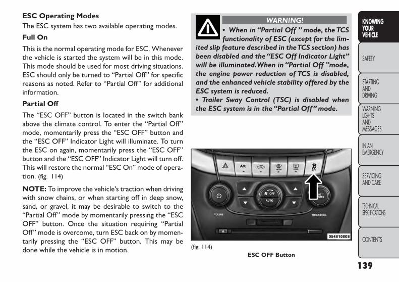
ESC Operating ModesThe ESC system has two available operating modes.
Full On
This is the normal operating mode for ESC. Wheneverthe vehicle is started the system will be in this mode.This mode should be used for most driving situations.ESC should only be turned to “Partial Off” for specificreasons as noted. Refer to “Partial Off” for additionalinformation.
Partial Off
The “ESC OFF” button is located in the switch bankabove the climate control. To enter the “Partial Off”mode, momentarily press the “ESC OFF” button andthe “ESC OFF” Indicator Light will illuminate. To turnthe ESC on again, momentarily press the “ESC OFF”button and the “ESC OFF” Indicator Light will turn off.This will restore the normal “ESC On” mode of opera-tion. (fig. 114)
NOTE: To improve the vehicle's traction when drivingwith snow chains, or when starting off in deep snow,sand, or gravel, it may be desirable to switch to the“Partial Off” mode by momentarily pressing the “ESCOFF” button. Once the situation requiring “PartialOff” mode is overcome, turn ESC back on by momen-tarily pressing the “ESC OFF” button. This may bedone while the vehicle is in motion.
WARNING!• When in “Partial Off ” mode, the TCSfunctionality of ESC (except for the lim-
ited slip feature described in theTCS section) hasbeen disabled and the “ESC Off Indicator Light”will be illuminated.When in “Partial Off ”mode,the engine power reduction of TCS is disabled,and the enhanced vehicle stability offered by theESC system is reduced.• Trailer Sway Control (TSC) is disabled whenthe ESC system is in the “Partial Off” mode.
(fig. 114)ESC OFF Button
139
KNOWINGYOURVEHICLE
SAFETY
STARTINGANDDRIVING
WARNINGLIGHTSANDMESSAGES
IN ANEMERGENCY
SERVICINGAND CARE
TECHNICALSPECIFICATIONS
CONTENTS

ESC ACTIVATION/MALFUNCTIONINDICATOR LIGHT AND ESC OFFINDICATOR LIGHT
The “ESC Activation/Malfunction IndicatorLight” in the instrument cluster will come onwhen the ignition switch is turned to the ONposition. It should go out with the engine
running. If the “ESC Activation/Malfunction IndicatorLight” comes on continuously with the engine running,a malfunction has been detected in the ESC system. Ifthis light remains on after several ignition cycles, andthe vehicle has been driven several kilometers atspeeds greater than 48 km/h, see your authorizeddealer as soon as possible to have the problem diag-nosed and corrected.
The “ESC Activation/Malfunction Indicator Light” (lo-cated in the instrument cluster) starts to flash as soonas the tires lose traction and the ESC system becomesactive. The “ESC Activation/Malfunction IndicatorLight” also flashes when TCS is active. If the “ESCActivation/Malfunction Indicator Light” begins to flashduring acceleration, ease up on the accelerator andapply as little throttle as possible. Be sure to adapt yourspeed and driving to the prevailing road conditions.
NOTE:
• The “ESC Activation/Malfunction Indicator Light”and the “ESC OFF Indicator Light” come on momen-tarily each time the ignition switch is turned ON.
• Each time the ignition is turned ON, the ESC systemwill be ON even if it was turned off previously.
• The ESC system will make buzzing or clicking soundswhen it is active. This is normal; the sounds will stopwhen ESC becomes inactive following the maneuverthat caused the ESC activation.
The “ESC OFF Indicator Light” indicates theElectronic Stability Control (ESC) is in PartialOFF mode.
Hill Start Assist (HSA)The HSA system is designed to assist the driver whenstarting a vehicle from a stop on a hill. HSA willmaintain the level of brake pressure the driver appliedfor a short period of time after the driver takes theirfoot off of the brake pedal. If the driver does not applythe throttle during this short period of time, thesystem will release brake pressure and the vehicle willroll down the hill. The system will release brake pres-sure in proportion to the amount of throttle applied asthe vehicle starts to move in the intended direction oftravel.
140
KNOWINGYOUR
VEHICLE
SAFETY
STARTINGAND
DRIVING
WARNINGLIGHTS
ANDMESSAGES
IN ANEMERGENCY
SERVICINGAND CARE
TECHNICALSPECIFICATIONS
CONTENTS

HSA Activation Criteria
The following criteria must be met in order for HSA toactivate:
• Vehicle must be stopped.
• Vehicle must be on a 6% (approximate) grade orgreater hill.
• Gear selection matches vehicle uphill direction (i.e.,vehicle facing uphill is in forward gear; vehicle backinguphill is in REVERSE gear).
WARNING!There may be situations on minor hillswith a loaded vehicle, or while pulling a
trailer where the system will not activate andslight rolling may occur, which could cause acollision with another vehicle or object. Alwaysremember the driver is responsible for brakingthe vehicle.
HSA will work in REVERSE and all forward gears whenthe activation criteria have been met. The system willnot activate if the vehicle is placed in NEUTRAL orPARK.
Towing With HSA
HSA will provide assistance when starting on a gradewhen pulling a trailer.
WARNING!• If you use a trailer brake controllerwith your trailer,your trailer brakes may
be activated and deactivated with the brakeswitch. If so, when the brake pedal is released,there may not be enough brake pressure to holdthe vehicle and trailer on a hill and this couldcause a collision with another vehicle or objectbehind you. In order to avoid rolling down the hillwhile resuming acceleration, manually activatethe trailer brake prior to releasing the brakepedal.Always remember the driver is responsiblefor braking the vehicle.• HSA is not a parking brake. If you stop thevehicle on a hill without putting the transmissionin PARK and using the parking brake, it will rolldown the hill and could cause a collision withanother vehicle or object. Always remember touse the parking brake while parking on a hill,andthat the driver is responsible for braking thevehicle.
141
KNOWINGYOURVEHICLE
SAFETY
STARTINGANDDRIVING
WARNINGLIGHTSANDMESSAGES
IN ANEMERGENCY
SERVICINGAND CARE
TECHNICALSPECIFICATIONS
CONTENTS

HSA Off
If you wish to turn off the HSA system, it can be doneusing the Customer Programmable Features in theElectronic Vehicle Information Center (EVIC). Refer to“Electronic Vehicle Information Center (EVIC)” in“Knowing your vehicle” for further information.
TRAILER SWAY CONTROL (TSC)TSC uses sensors in the vehicle to recognize an exces-sively swaying trailer. TSC activates automatically oncethe excessively swaying trailer is recognized. WhenTSC is functioning, the “ESC Activation/MalfunctionIndicator Light” will flash, the engine power will bereduced, and you will feel the brake being applied toindividual wheels in an attempt to stop the trailer fromswaying.
NOTE: The TSC is disabled when the ESC system is inthe “Partial Off” mode.
WARNING!• TSC cannot stop all trailers fromswaying. Always use caution when tow-
ing a trailer and follow the tongue weight recom-mendations.Refer to“TrailerTowing”in“Startingand Driving” for further information.• IfTSC activates while towing a trailer, stop thevehicle at the nearest safe location and adjustthe trailer load to eliminate the trailer sway.• Failure to follow these warnings can result in anaccident or serious personal injury.
142
KNOWINGYOUR
VEHICLE
SAFETY
STARTINGAND
DRIVING
WARNINGLIGHTS
ANDMESSAGES
IN ANEMERGENCY
SERVICINGAND CARE
TECHNICALSPECIFICATIONS
CONTENTS

ONBOARD DIAGNOSTIC SYSTEM —OBD IIYour vehicle is equipped with a sophisticated onboarddiagnostic system called OBD II. This system monitorsthe performance of the emissions, engine, and auto-matic transmission control systems. When these sys-tems are operating properly, your vehicle will provideexcellent performance and fuel economy, as well asengine emissions well within current government regu-lations.
If any of these systems require service, the OBD IIsystem will turn on the “Malfunction Indicator Light”(MIL). It will also store diagnostic codes and otherinformation to assist your service technician in makingrepairs. Although your vehicle will usually be drivableand not need towing, see your authorized dealer forservice as soon as possible.
• Prolonged driving with the MIL oncould cause further damage to the emis-sion control system. It could also affect
fuel economy and driveability.The vehicle must beserviced before any emissions tests can be per-formed.• If the MIL is flashing while the engine is running,severe catalytic converter damage and power losswill soon occur. Immediate service is required.
LOOSE FUEL FILLER CAP MESSAGE(for versions/markets, where provided)If the vehicle diagnostic system determines that thefuel filler cap is loose, improperly installed, or damaged,a “Check Gascap” message will display in the ElectronicVehicle Information Center (EVIC). If this occurs,tighten the fuel filler cap properly and press the TRIPODOMETER button to turn off the message. If theproblem continues, the message will appear the nexttime the vehicle is started.
A loose, improperly installed, or damaged fuel filler capmay also turn on the MIL.
143
KNOWINGYOURVEHICLE
SAFETY
STARTINGANDDRIVING
WARNINGLIGHTSANDMESSAGES
IN ANEMERGENCY
SERVICINGAND CARE
TECHNICALSPECIFICATIONS
CONTENTS

POWER STEERINGThe standard power steering system will give you goodvehicle response and increased ease of maneuverabilityin tight spaces. The system will provide mechanicalsteering capability if power assist is lost.
If for some reason the power assist is interrupted, itwill still be possible to steer your vehicle. Under theseconditions, you will observe a substantial increase insteering effort, especially at very low vehicle speedsand during parking maneuvers.
NOTE:
• Increased noise levels at the end of the steeringwheel travel are considered normal and do notindicate that there is a problem with the powersteering system.
• Upon initial start-up in cold weather, the powersteering pump may make noise for a short amount oftime. This is due to the cold, thick fluid in thesteering system. This noise should be considerednormal, and it does not in any way damage thesteering system.
WARNING!Continued operation with reducedpower steering assist could pose a safety
risk to yourself and others. Service should beobtained as soon as possible.
Prolonged operation of the steering sys-tem at the end of the steering wheeltravel will increase the steering fluid tem-
perature and it should be avoided when possible.Damage to the power steering pump may occur.
POWER STEERING FLUID CHECKChecking the power steering fluid level at a definedservice interval is not required. The fluid should only bechecked if a leak is suspected, abnormal noises areapparent, and/or the system is not functioning as an-ticipated. Coordinate inspection efforts through anauthorized dealer.
144
KNOWINGYOUR
VEHICLE
SAFETY
STARTINGAND
DRIVING
WARNINGLIGHTS
ANDMESSAGES
IN ANEMERGENCY
SERVICINGAND CARE
TECHNICALSPECIFICATIONS
CONTENTS

Do not use chemical flushes in yourpower steering system as the chemicalscan damage your power steering compo-
nents. Such damage is not covered by the NewVehicle LimitedWarranty.
WARNING!Fluid level should be checked on a levelsurface and with the engine off to pre-
vent injury from moving parts and to ensureaccurate fluid level reading. Do not overfill. Useonly manufacturer's recommended power steer-ing fluid.
If necessary, add fluid to restore to the proper indi-cated level. With a clean cloth, wipe any spilled fluidfrom all surfaces.
TIRE PRESSURE MONITOR SYSTEM(TPMS)The Tire Pressure Monitor System (TPMS) will warnthe driver of a low tire pressure based on the vehiclerecommended cold placard pressure.
The tire pressure will vary with temperature by about0.07 BAR for every 6.5°C. This means that when theoutside temperature decreases, the tire pressure willdecrease. Tire pressure should always be set based oncold inflation tire pressure. This is defined as the tirepressure after the vehicle has not been driven for atleast three hours, or driven less than 1.6 km after athree hour period. The cold tire inflation pressuremust not exceed the maximum inflation pressuremolded into the tire sidewall. Refer to “Tires – GeneralInformation” in “Technical Specifications” for informa-tion on how to properly inflate the vehicle’s tires. Thetire pressure will also increase as the vehicle is driven.This is normal and there should be no adjustment forthis increased pressure.
145
KNOWINGYOURVEHICLE
SAFETY
STARTINGANDDRIVING
WARNINGLIGHTSANDMESSAGES
IN ANEMERGENCY
SERVICINGAND CARE
TECHNICALSPECIFICATIONS
CONTENTS
The TPMS will warn the driver of a low tire pressure ifthe tire pressure falls below the low-pressure warninglimit for any reason, including low temperature effectsand natural pressure loss through the tire.
The TPMS will continue to warn the driver of low tirepressure as long as the condition exists, and will notturn off until the tire pressure is at or above therecommended cold placard pressure. Once the lowtire pressure warning (Tire Pressure Monitoring Tell-tale Light) illuminates, you must increase the tire pres-sure to the recommended cold placard pressure inorder for the Tire Pressure Monitoring Telltale Light toturn off. The system will automatically update and theTire Pressure Monitoring Telltale Light will turn offonce the system receives the updated tire pressures.The vehicle may need to be driven for up to 20 minutesabove 25 km/h in order for the TPMS to receive thisinformation.
• The TPMS has been optimized for theoriginal equipment tires and wheels.TPMS pressures and warning have been
established for the tire size equipped on yourvehicle. Undesirable system operation or sensordamage may result when using replacementequipment that is not of the same size, type,and/or style.Aftermarket wheels can cause sensordamage. Using aftermarket tire sealants maycause the Tire Pressure Monitoring System(TPMS) sensor to become inoperable.After usingan aftermarket tire sealant it is recommendedthat you take your vehicle to your local dealershipto have your sensor function checked.• After inspecting or adjusting the tire pressure,always reinstall the valve stem cap.This will pre-vent moisture and dirt from entering the valvestem,which could damage theTire Pressure Moni-toring Sensor.
146
KNOWINGYOUR
VEHICLE
SAFETY
STARTINGAND
DRIVING
WARNINGLIGHTS
ANDMESSAGES
IN ANEMERGENCY
SERVICINGAND CARE
TECHNICALSPECIFICATIONS
CONTENTS

NOTE:
• The TPMS is not intended to replace normal tire careand maintenance, or to provide warning of a tirefailure or condition.
• The TPMS should not be used as a tire pressuregauge while adjusting your tire pressure.
• Driving on a significantly under-inflated tire causesthe tire to overheat and can lead to tire failure.Under-inflation also reduces fuel efficiency and tiretread life, and may affect the vehicle’s handling andstopping ability.
• The TPMS is not a substitute for proper tire mainte-nance, and it is the driver’s responsibility to maintaincorrect tire pressure using an accurate tire pressuregauge, even if under-inflation has not reached thelevel to trigger illumination of the Tire PressureMonitoring Telltale Light.
• Seasonal temperature changes will affect tire pres-sure, and the TPMS will monitor the actual tirepressure in the tire.
BASE SYSTEMThe Tire Pressure Monitor System (TPMS) uses wirelesstechnology with wheel rim mounted electronic sensorsto monitor tire pressure levels. Sensors, mounted to eachwheel as part of the valve stem, transmit tire pressurereadings to the receiver module.
NOTE: It is particularly important for you to checkthe tire pressure in all of the tires on your vehiclemonthly and to maintain the proper pressure.
The TPMS consists of the following components:
• Receiver Module
• Four Tire Pressure Monitoring Sensors
• Tire Pressure Monitoring Telltale Light
Tire Pressure Monitoring Low PressureWarnings
The Tire Pressure Monitoring Telltale Light willilluminate in the instrument cluster and a chime
will sound when tire pressure is low in one or more ofthe four active road tires. Should this occur, you shouldstop as soon as possible, check the inflation pressure ofeach tire on your vehicle, and inflate each tire to thevehicle’s recommended cold placard pressure value.Once the system receives the updated tire pressures,the system will automatically update and the TirePressure Monitoring Telltale Light will turn off. Thevehicle may need to be driven for up to 20 minutesabove 25 km/h in order for the TPMS to receive thisinformation.
147
KNOWINGYOURVEHICLE
SAFETY
STARTINGANDDRIVING
WARNINGLIGHTSANDMESSAGES
IN ANEMERGENCY
SERVICINGAND CARE
TECHNICALSPECIFICATIONS
CONTENTS
ServiceTPMS WarningWhen a system fault is detected, the Tire PressureMonitoring Telltale Light will flash on and off for 75 sec-onds and then remain on solid. The system fault willalso sound a chime. If the ignition switch is cycled, thissequence will repeat, providing the system fault stillexists. The Tire Pressure Monitoring Telltale Light willturn off when the fault condition no longer exists.A system fault can occur due to any of the following:
1. Jamming due to electronic devices or driving next tofacilities emitting the same Radio Frequencies as theTPMS sensors.
2. Installing some form of aftermarket window tintingthat affects radio wave signals.
3. Lots of snow or ice around the wheels or wheelhousings.
4. Using tire chains on the vehicle.
5. Using wheels/tires not equipped with TPMS sensors.
NOTE:
1. The compact spare tire does not have a tire pres-sure monitoring sensor. Therefore, the TPMS willnot monitor the pressure in the compact spare tire.
2. If you install the compact spare tire in place of a roadtire that has a pressure below the low-pressure warn-ing limit, a chime will sound and the TPMS TelltaleLight will turn on upon the next ignition switch cycle.
3. After driving the vehicle for up to 20 minutes above25 km/h, the TPMS Telltale Light will flash on and offfor 75 seconds and then remain on solid.
4. For each subsequent ignition switch cycle, a chimewill sound and the TPMS Telltale Light will flash onand off for 75 seconds and then remain on solid.
5. Once you repair or replace the original road tire andreinstall it on the vehicle in place of the compactspare, the TPMS will update automatically and theTPMS Telltale Light will turn off, as long as no tirepressure is below the low-pressure warning limit inany of the four active road tires. The vehicle mayneed to be driven for up to 20 minutes above25 km/h in order for the TPMS to receive thisinformation.
148
KNOWINGYOUR
VEHICLE
SAFETY
STARTINGAND
DRIVING
WARNINGLIGHTS
ANDMESSAGES
IN ANEMERGENCY
SERVICINGAND CARE
TECHNICALSPECIFICATIONS
CONTENTS

TPMS Deactivation And Reactivation —(for versions/markets, where provided)The TPMS can be deactivated if replacing all four wheeland tire assemblies (road tires) with wheel and tireassemblies that do not have TPMS Sensors, such aswhen installing winter wheel and tire assemblies onyour vehicle.
To deactivate the TPMS, first, replace all four wheel andtire assemblies (road tires) with those not equippedwith TPM Sensors. Then, drive the vehicle for at least20 minutes above 25 km/h. The TPMS will chime andthe TPM Telltale Light will flash on and off for 75 sec-onds and then remain on solid. Upon the next ignitionswitch cycle, the TPMS will no longer chime or turn onthe Tire Pressure Monitoring Telltale Light.
To reactivate the TPMS, first, replace all four wheel andtire assemblies (road tires) with those equipped withTPM Sensors. Then, drive the vehicle for up to 20 min-utes above 25 km/h. The TPMS will chime and the TirePressure Monitoring Telltale Light will flash on and offfor 75 seconds.
PREMIUM SYSTEM (for versions/markets,where provided)The Tire Pressure Monitor System (TPMS) uses wire-less technology with wheel rim mounted electronicsensors to monitor tire pressure levels. Sensors,mounted to each wheel as part of the valve stem,transmit tire pressure readings to the receiver module.
NOTE: It is particularly important for you to checkthe tire pressure in all of the tires on your vehiclemonthly and to maintain the proper pressure.
The TPMS consists of the following components:
• Receiver module
• Four Tire Pressure Monitoring Sensors
• Various Tire Pressure Monitoring System messages,which display in the Electronic Vehicle InformationCenter (EVIC)
• Tire Pressure Monitoring Telltale Light
149
KNOWINGYOURVEHICLE
SAFETY
STARTINGANDDRIVING
WARNINGLIGHTSANDMESSAGES
IN ANEMERGENCY
SERVICINGAND CARE
TECHNICALSPECIFICATIONS
CONTENTS

Tire Pressure Monitoring Low PressureWarnings
The Tire Pressure Monitoring Telltale Light willilluminate in the instrument cluster and a chime
will sound when tire pressure is low in one or more ofthe four active road tires. In addition, the ElectronicVehicle Information Center (EVIC) will display agraphic showing the pressure values of each tire withthe low tire pressure values in a different color. An"Inflate Tire to XXX" message will also be displayed.
Should this occur, you should stop as soon as possibleand inflate the tires with low pressure (those displayedin a different color in the EVIC graphic) to the vehicle’srecommended cold placard pressure value as shown inthe "Inflate Tire to XXX" message. Once the systemreceives the updated tire pressures, the system willautomatically update, the graphic display in the EVICwill return to the original color, and the Tire PressureMonitoring Telltale Light will turn off. The vehicle mayneed to be driven for up to 20 minutes above 25 km/hin order for the TPMS to receive this information.
ServiceTPMS WarningWhen a system fault is detected, the Tire PressureMonitoring Telltale Light will flash on and off for 75 sec-onds and then remain on solid. The system fault willalso sound a chime. In addition, the EVIC will display a"SERVICE TPM SYSTEM" message for a minimum offive seconds and then display dashes (- -) in place of thepressure value to indicate which sensor is not beingreceived.
If the ignition switch is cycled, this sequence will repeat,providing the system fault still exists. If the system faultno longer exists, the Tire Pressure Monitoring TelltaleLight will no longer flash, and the "SERVICE TPMSYSTEM" message will no longer display, and a pressurevalue will display in place of the dashes. A system faultcan occur due to any of the following:
1. Jamming due to electronic devices or driving next tofacilities emitting the same radio frequencies as theTPMS sensors.
2. Installing some form of aftermarket window tintingthat affects radio wave signals.
3. Lots of snow or ice around the wheels or wheelhousings.
150
KNOWINGYOUR
VEHICLE
SAFETY
STARTINGAND
DRIVING
WARNINGLIGHTS
ANDMESSAGES
IN ANEMERGENCY
SERVICINGAND CARE
TECHNICALSPECIFICATIONS
CONTENTS

4. Using tire chains on the vehicle.
5. Using wheels/tires not equipped with TPMS sen-sors.
The EVIC will also display a "SERVICE TPM SYSTEM"message for a minimum of five seconds when a systemfault related to an incorrect sensor location fault isdetected. In this case, the "SERVICE TPM SYSTEM"message is then followed with a graphic display withpressure values still shown. This indicates that thepressure values are still being received from the TPMsensors but they may not be located in the correctvehicle position. The system still needs to be servicedas long as the "SERVICE TPM SYSTEM" message isdisplayed.
NOTE:
1. The compact spare tire does not have a tire pres-sure monitoring sensor. Therefore, the TPMS willnot monitor the pressure in the compact spare tire.
2. If you install the compact spare tire in place of a roadtire that has a pressure below the low-pressurewarning limit, upon the next ignition switch cycle,the TPMS Telltale Light will remain on and a chimewill sound. In addition, the graphic in the EVIC willstill display a different color pressure value. An"Inflate Tire to XXX" message will also be displayed.
3. After driving the vehicle for up to 20 minutes above25 km/h, the TPMS Telltale Light will flash on and offfor 75 seconds and then remain on solid. In addition,the EVIC will display a "SERVICE TPM SYSTEM"message for a minimum of five seconds and thendisplay dashes (- -) in place of the pressure value.
4. For each subsequent ignition switch cycle, a chimewill sound, the TPMS Telltale Light will flash on andoff for 75 seconds and then remain on solid, and theEVIC will display a "SERVICE TPM SYSTEM" mes-sage for a minimum of five seconds and then displaydashes (- -) in place of the pressure value.
5. Once you repair or replace the original road tire andreinstall it on the vehicle in place of the compactspare, the TPMS will update automatically. In addi-tion, the TPMS Telltale Light will turn off and thegraphic in the EVIC will display a new pressure valueinstead of dashes (- -), as long as no tire pressure isbelow the low-pressure warning limit in any of thefour active road tires. The vehicle may need to bedriven for up to 20 minutes above 25 km/h in orderfor the TPMS to receive this information.
151
KNOWINGYOURVEHICLE
SAFETY
STARTINGANDDRIVING
WARNINGLIGHTSANDMESSAGES
IN ANEMERGENCY
SERVICINGAND CARE
TECHNICALSPECIFICATIONS
CONTENTS

TPMS Deactivation And Reactivation —(for versions/markets, where provided)The TPMS can be deactivated if replacing all four wheeland tire assemblies (road tires) with wheel and tireassemblies that do not have TPMS Sensors, such aswhen installing winter wheel and tire assemblies onyour vehicle.
To deactivate the TPMS, first, replace all four wheel andtire assemblies (road tires) with those not equippedwith TPM Sensors. Then, drive the vehicle for 20 min-utes above 25 km/h. The TPMS will chime and the TirePressure Monitoring Telltale Light will flash on and offfor 75 seconds and then remain on solid. In addition,the Electronic Vehicle Information Center (EVIC) willdisplay a “SERVICE TPM SYSTEM” text message, andthe graphic will display “- -“ in place of four tirepressure values. Upon the next ignition switch cycle,the TPMS will no longer chime or turn on the TirePressure Monitoring Telltale Light, or display the textmessage in the EVIC. However, the graphic will stilldisplay “- -.“
To reactivate the TPMS, first, replace all four wheel andtire assemblies (road tires) with those equipped withTPM Sensors. Then, drive the vehicle for up to 20 min-utes above 25 km/h. The TPMS will chime, the Tire
Pressure Monitoring Telltale Light will flash on and offfor 75 seconds, the EVIC will display a “SERVICE TPMSYSTEM” text message, and the graphic will display tirepressure values to show that the TPMS is receivingsensor data.
GENERAL INFORMATIONTransmitter and receivers operate on a carrier fre-quency of 433.92 MHz as required by EEC regulations.These devices must be certified to conform to specificregulations in each individual country. Two sets ofregulations are involved: ETS (European Telecommuni-cation Standard) 300–220, which most countries use,and German BZT federal regulation 225Z125, which isbased on ETC 300–220 but has additional unique re-quirements. Other defined requirements are noted inANNEX VI of COMMISSION DIRECTIVE 95/56/EC.Operation is subject to the following two conditions:
• This device may not cause harmful interference.
• This device must accept any interference received,including interference that may cause undesired op-eration.
152
KNOWINGYOUR
VEHICLE
SAFETY
STARTINGAND
DRIVING
WARNINGLIGHTS
ANDMESSAGES
IN ANEMERGENCY
SERVICINGAND CARE
TECHNICALSPECIFICATIONS
CONTENTS

REAR PARK ASSIST (for versions/markets, where provided)The Rear Park Assist system provides visual and audibleindications of the distance between the rear fascia anda detected obstacle when backing up, e.g. during aparking maneuver. Refer to “Park Assist System UsagePrecautions” for limitations of this system and recom-mendations.
Park Assist will retain the last system state (enabled ordisabled) from the last ignition cycle when the ignitionis changed to the ON/RUN position.
Park Assist can be active only when the shift lever is inREVERSE. If Park Assist is enabled at this shift leverposition, the system will remain active until the vehiclespeed is increased to approximately 11 km/h or above.The system will become active again if the vehiclespeed is decreased to speeds less than approximately9 km/h.
PARK ASSIST SENSORSThe four Park Assist sensors, located in the rearfascia/bumper, monitor the area behind the vehicle thatis within the sensors’ field of view. The sensors candetect obstacles from approximately 30 cm up to200 cm from the rear fascia/bumper in the horizontaldirection, depending on the location, type and orienta-tion of the obstacle.
PARK ASSIST WARNING DISPLAYThe Park Assist Warning screen will only be displayed ifSound and Display is selected from the Uconnect®System. Refer to “Uconnect® Settings” for furtherinformation.
The Park Assist Warning screen is located within theElectronic Vehicle Information Center (EVIC). It pro-vides visual warnings to indicate the distance betweenthe rear fascia/bumper and the detected obstacle. Re-fer to “Electronic Vehicle Information Center (EVIC)/Settings” for further information.
153
KNOWINGYOURVEHICLE
SAFETY
STARTINGANDDRIVING
WARNINGLIGHTSANDMESSAGES
IN ANEMERGENCY
SERVICINGAND CARE
TECHNICALSPECIFICATIONS
CONTENTS

PARK ASSIST DISPLAYWhen the vehicle is in REVERSE, the warning display willturn ON indicating the system status. (fig. 115) (fig. 116)
(fig. 115)Park Assist Ready
(fig. 116)Park Assist System Off
154
KNOWINGYOUR
VEHICLE
SAFETY
STARTINGAND
DRIVING
WARNINGLIGHTS
ANDMESSAGES
IN ANEMERGENCY
SERVICINGAND CARE
TECHNICALSPECIFICATIONS
CONTENTS

The system will indicate a detected obstacle by show-ing three solid arcs and will produce a one-half secondtone. As the vehicle moves closer to the object, theEVIC display will show fewer arcs and the sound tonewill change from slow, to fast, to continuous. (fig. 117)(fig. 118) (fig. 119)
(fig. 117)SlowTone
(fig. 118)FastTone
(fig. 119)ContinuousTone
155
KNOWINGYOURVEHICLE
SAFETY
STARTINGANDDRIVING
WARNINGLIGHTSANDMESSAGES
IN ANEMERGENCY
SERVICINGAND CARE
TECHNICALSPECIFICATIONS
CONTENTS

The vehicle is close to the obstacle when the warningdisplay shows one flashing arc and sounds a continuoustone. The following chart shows the warning alertoperation when the system is detecting an obstacle:
WARNING ALERTSRear Distance
(cm)Greater than
200 cm200-100 cm 100-65 cm 65-30 cm Less than
30 cmAudible Alert
ChimeNone Single 1/2-
Second ToneSlow Fast Continuous
Arcs None 3 Solid(Continuous)
3 SlowFlashing
2 SlowFlashing
1 SlowFlashing
ENABLING AND DISABLING PARK ASSISTPark Assist can be enabled and disabled using theUconnect® System. The available choices are: Off,Sound Only, or Sound and Display. Refer to“Uconnect® Settings” for further information.
When the Park Assist soft-key is pressed to disable thesystem, the EVIC will display the “PARK ASSIST SYS-TEM OFF” message for approximately five seconds.Refer to “Electronic Vehicle Information Center(EVIC)” for further information. When the shift lever ismoved to REVERSE and the system is disabled, theEVIC will display the “PARK ASSIST SYSTEM OFF”message for as long as the vehicle is in REVERSE at orbelow 11 km/h.
SERVICETHE REAR PARK ASSIST SYSTEMDuring vehicle start up, when the Rear Park Assistsystem has detected a fault condition, the ElectronicVehicle Information Center (EVIC) will actuate a singlechime, once per ignition cycle, and it will display the“CLEAN PARK ASSIST”, “SERVICE PARK ASSIST” or“SERVICE PARK ASSIST SYSTEM” message. Refer to“Electronic Vehicle Information Center (EVIC)” forfurther information. When the shift lever is moved toREVERSE and the system has detected a fault condi-tion, the EVIC will display the “CLEAN PARK ASSIST”,“SERVICE PARK ASSIST” or “SERVICE PARK ASSISTSYSTEM” message for as long as the vehicle is inREVERSE. Under this condition, Park Assist will notoperate.
156
KNOWINGYOUR
VEHICLE
SAFETY
STARTINGAND
DRIVING
WARNINGLIGHTS
ANDMESSAGES
IN ANEMERGENCY
SERVICINGAND CARE
TECHNICALSPECIFICATIONS
CONTENTS

If “CLEAN PARK ASSIST” appears in the ElectronicVehicle Information Center (EVIC) make sure theouter surface and the underside of the rear fascia/bumper is clean and clear of snow, ice, mud, dirt orother obstruction and then cycle the ignition. If themessage continues to appear see an authorized dealer.
If “SERVICE PARK ASSIST” or “SERVICE PARK ASSISTSYSTEM” appears in the EVIC, see your authorizeddealer.
CLEANINGTHE PARK ASSIST SYSTEMClean the sensors with water, car wash soap and a softcloth. Do not use rough or hard cloths. Do not scratchor poke the sensors. Otherwise, you could damage thesensors.
PARK ASSIST SYSTEM USAGE PRECAUTIONS
NOTE:
• Ensure that the rear bumper is free of snow, ice,mud, dirt and debris to keep the Park Assist systemoperating properly.
• Jackhammers, large trucks, and other vibrationscould affect the performance of Park Assist.
• When you turn Park Assist off, the EVIC will display“PARK ASSIST SYSTEM OFF.” Furthermore, onceyou turn Park Assist off, it remains off until you turnit on again, even if you cycle the ignition key.
• When you move the shift lever to the REVERSEposition and Park Assist is turned off, the EVIC willdisplay the “PARK ASSIST SYSTEM OFF” messagefor as long as the vehicle is in REVERSE.
• Clean the Park Assist sensors regularly, taking carenot to scratch or damage them. The sensors mustnot be covered with ice, snow, slush, mud, dirt ordebris. Failure to do so can result in the system notworking properly. The Park Assist system might notdetect an obstacle behind the fascia/bumper, or itcould provide a false indication that an obstacle isbehind the fascia/bumper.
• Ensure that the Park Assist system is turned OFF ifobjects such as bicycle carriers, trailer hitches, etc.,are placed within 30 cm from the rear fascia/bumperwhile driving the vehicle. Failure to do so can result inthe system misinterpreting a close object as a sensorproblem, causing the “SERVICE PARK ASSIST” mes-sage to be displayed in the EVIC.
157
KNOWINGYOURVEHICLE
SAFETY
STARTINGANDDRIVING
WARNINGLIGHTSANDMESSAGES
IN ANEMERGENCY
SERVICINGAND CARE
TECHNICALSPECIFICATIONS
CONTENTS

• ParkAssist is only a parking aid and it isunable to recognize every obstacle, in-cluding small obstacles. Parking curbs
might be temporarily detected or not detected atall. Obstacles located above or below the sensorswill not be detected when they are in close prox-imity.• The vehicle must be driven slowly when usingParkAssist in order to be able to stop in time whenan obstacle is detected. It is recommended thatthe driver looks over his/her shoulder when usingPark Assist.
WARNING!• Drivers must be careful when backingup even when using Park Assist. Always
check carefully behind your vehicle, look behindyou, and be sure to check for pedestrians, ani-mals,other vehicles,obstructions,and blind spotsbefore backing up.You are responsible for safetyand must continue to pay attention to your sur-roundings. Failure to do so can result in seriousinjury or death.
(Continued)
(Continued)• Before using Park Assist, it is strongly recom-mended that the ball mount and hitch ball as-sembly is disconnected from the vehicle when thevehicle is not used for towing.Failure to do so canresult in injury or damage to vehicles or obstaclesbecause the hitch ball will be much closer to theobstacle than the rear fascia when the loud-speaker sounds the continuous tone. Also, thesensors could detect the ball mount and hitch ballassembly, depending on its size and shape, givinga false indication that an obstacle is behind thevehicle.
158
KNOWINGYOUR
VEHICLE
SAFETY
STARTINGAND
DRIVING
WARNINGLIGHTS
ANDMESSAGES
IN ANEMERGENCY
SERVICINGAND CARE
TECHNICALSPECIFICATIONS
CONTENTS

PARKVIEW® REAR BACK UPCAMERA (for versions/markets,where provided)Your vehicle may be equipped with the ParkView®Rear Back Up Camera that allows you to see anon-screen image of the rear surroundings of yourvehicle whenever the shift lever is put into REVERSE.The image will be displayed on the radio touchscreendisplay along with a caution note to “check entiresurroundings” across the top of the screen. After fiveseconds this note will disappear. The ParkView® cam-era is located on the rear of the vehicle above the rearLicense plate.
When the vehicle is shifted out of REVERSE, the rearcamera mode is exited and the navigation or audioscreen appears again.
When displayed, static grid lines will illustrate thewidth of the vehicle and will show separate zones thatwill help indicate the distance to the rear of the vehicle.The following table shows the approximate distancesfor each zone:
Zone Distance to the rear of the vehicleRed 0 - 30 cm
Yellow 30 cm - 1 mGreen 1 m or greater
WARNING!Drivers must be careful when backing upeven when using the ParkView® Rear
Back Up Camera.Always check carefully behindyour vehicle, and be sure to check for pedestri-ans,animals,other vehicles,obstructions,or blindspots before backing up.You are responsible for
(Continued)
(Continued)the safety of your surroundings and must con-tinue to pay attention while backing up. Failureto do so can result in serious injury or death.
159
KNOWINGYOURVEHICLE
SAFETY
STARTINGANDDRIVING
WARNINGLIGHTSANDMESSAGES
IN ANEMERGENCY
SERVICINGAND CARE
TECHNICALSPECIFICATIONS
CONTENTS
• To avoid vehicle damage, ParkView®should only be used as a parking aid.TheParkView® camera is unable to view ev-
ery obstacle or object in your drive path.• To avoid vehicle damage, the vehicle must bedriven slowly when using ParkView® to be able tostop in time when an obstacle is seen. It is recom-mended that the driver look frequently over his/her shoulder when using ParkView®.
NOTE: If snow, ice, mud, or any foreign substancebuilds up on the camera lens, clean the lens, rinse withwater, and dry with a soft cloth. Do not cover the lens.
TURNING PARKVIEW® ON OR OFF —WITHTOUCH SCREENPerform the following steps on the touch screen toturn the Parkview® Backup Camera ON or OFF:
1. Press the “More” soft-key.
2. Press the “Settings” soft-key.
3. Press the “Safety & Driving Assistance” soft-key.
4. Press the check box soft key next to “Parkview®Backup Camera” to enable/disable.
NAVIGATION SYSTEM(for versions/markets, whereprovided)Refer to your Uconnect® User Manual.
160
KNOWINGYOUR
VEHICLE
SAFETY
STARTINGAND
DRIVING
WARNINGLIGHTS
ANDMESSAGES
IN ANEMERGENCY
SERVICINGAND CARE
TECHNICALSPECIFICATIONS
CONTENTS

SOUND SYSTEMSRefer to your Uconnect® User Manual.
STEERING WHEEL AUDIOCONTROLSThe remote sound system controls are located on therear surface of the steering wheel. The left and right-hand controls are rocker-type switches with a pushbut-ton in the center of each switch. Reach behind thesteering wheel to access the switches. (fig. 120)
(fig. 120)Remote Sound Controls (BackView Of Steering Wheel)
161
KNOWINGYOURVEHICLE
SAFETY
STARTINGANDDRIVING
WARNINGLIGHTSANDMESSAGES
IN ANEMERGENCY
SERVICINGAND CARE
TECHNICALSPECIFICATIONS
CONTENTS
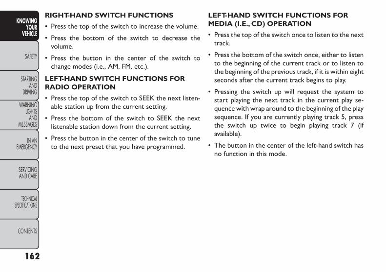
RIGHT-HAND SWITCH FUNCTIONS
• Press the top of the switch to increase the volume.
• Press the bottom of the switch to decrease thevolume.
• Press the button in the center of the switch tochange modes (i.e., AM, FM, etc.).
LEFT-HAND SWITCH FUNCTIONS FORRADIO OPERATION
• Press the top of the switch to SEEK the next listen-able station up from the current setting.
• Press the bottom of the switch to SEEK the nextlistenable station down from the current setting.
• Press the button in the center of the switch to tuneto the next preset that you have programmed.
LEFT-HAND SWITCH FUNCTIONS FORMEDIA (I.E., CD) OPERATION
• Press the top of the switch once to listen to the nexttrack.
• Press the bottom of the switch once, either to listento the beginning of the current track or to listen tothe beginning of the previous track, if it is within eightseconds after the current track begins to play.
• Pressing the switch up will request the system tostart playing the next track in the current play se-quence with wrap around to the beginning of the playsequence. If you are currently playing track 5, pressthe switch up twice to begin playing track 7 (ifavailable).
• The button in the center of the left-hand switch hasno function in this mode.
162
KNOWINGYOUR
VEHICLE
SAFETY
STARTINGAND
DRIVING
WARNINGLIGHTS
ANDMESSAGES
IN ANEMERGENCY
SERVICINGAND CARE
TECHNICALSPECIFICATIONS
CONTENTS

UCONNECT® MULTIMEDIA VIDEOENTERTAINMENT SYSTEM (VES™)(for versions/markets, whereprovided)Your rear seat Video Entertainment System (VES™) isdesigned to give your family years of enjoyment. Youcan play your favorite CDs or DVDs, listen to audioover the wireless headphones, or plug and play a varietyof standard video games or audio devices. Please re-view this Owner's Manual to become familiar with itsfeatures and operation.
Getting Started
• Screen located in the overhead console: Unfoldthe overhead LCD screen by pushing the button onthe overhead console behind the screen. (fig. 121)
• With the ignition switch in the ON or ACC position,turn the radio on by pushing the ON/OFF VolumeControl knob.
• When the Video Screen is open and a DVD isinserted into the radio, the screen turns on auto-matically, the headphone transmitters turn on andplayback begins.
(fig. 121)OverheadVideo Screen
163
KNOWINGYOURVEHICLE
SAFETY
STARTINGANDDRIVING
WARNINGLIGHTSANDMESSAGES
IN ANEMERGENCY
SERVICINGAND CARE
TECHNICALSPECIFICATIONS
CONTENTS

Video Screen
NOTE: Typically there are two different ways tooperate the features of the Video Entertainment Sys-tem (VES™).
• The Remote Control
• The Touch-Screen Radio (for versions/markets,where provided)
PlayVideo GamesConnect the video game console to the Auxiliary RCAinput jacks located on the back of the center console.
Audio/Video RCA Jacks (AUX Jacks)on the rear of the center consoleenable the monitor to display videodirectly from a video camera, con-nect video games for display on thescreen, or play music directly from an
MP3 player.
1. Video in (yellow)
2. Left audio in (white)
3. Right audio in (red)
When connecting an external source to the AUXinput, be sure to follow the standard color coding forthe VES™ jacks:
NOTE: Certain high-end video games, such as Playsta-tion3 and XBox360 will exceed the power limit of thevehicle's Power Inverter. Refer to the Power Invertersection in your vehicle's Owner's Manual for moreinformation.
Ensure the remote control channel selector switch andHeadphone switch (IR channel) are the same number.
UsingThe Remote Control
1. Press the MODE button on the Remote Control.
2. While looking at the video screen, highlight AUX 1,by either pressing Up/Down/Left/Right buttons orby repeatedly pressing the MODE button, thenpress ENTER on the Remote Control.
UsingTheTouchscreen Radio Controls
1. Touch the “MORE” soft-key.
2. Touch the “Rear Entertainment” soft-key to displaythe Rear Entertainment Controls.
3. If the Rear Entertainment is turned off, touch the“Power” soft-key.
4. Touch the “1” or “2” soft-key for the channeldesired and press “Source” soft-key to select thedesired mode.
164
KNOWINGYOUR
VEHICLE
SAFETY
STARTINGAND
DRIVING
WARNINGLIGHTS
ANDMESSAGES
IN ANEMERGENCY
SERVICINGAND CARE
TECHNICALSPECIFICATIONS
CONTENTS

ListenTo An Audio Source On Channel 2While AVideo Is Playing On Channel 1Ensure the Remote Control and Headphone switch ison Channel 2.
UsingThe Remote Control
1. Press the MODE button on the Remote Controland the Mode Select Screen will display, unless avideo is playing then only a small banner will appearon the bottom of the screen.
2. While looking at the video screen, either pressUp/ Down/Left/Right on the Remote Control tohighlight the desired audio source or repeatedlypress the MODE button on the remote until thedesired audio source appears on the screen.
UsingTheTouch-Screen Radio Controls
1. Touch the “MORE” soft-key.
2. Touch the “Rear Entertainment” soft-key to displaythe Rear Entertainment Controls.
3. If the Rear Entertainment is turned off, touch the“Power” soft-key.
4. Touch the “1” or “2” soft-key for the channeldesired then press the “SOURCE” soft key to selectthe desired mode.
Important Notes For SingleVideo ScreenSystem
• VES™ is able to transmit two channels of stereoaudio simultaneously.
• In split screen mode the left side equates to Chan-nel 1 and right side equates to Channel 2.
• If a video source is selected on Channel 1, thenChannel 2 is for audio only.
• When selecting a video source on Channel 1, thevideo will display on the screen and the audio will beheard on Channel 1 in the headphones.
• Audio can be heard through the headphones evenwhen the Video Screen is closed.
Play A DVD UsingTheTouchscreen Radio
1. Insert the DVD with the label facing up. The radioautomatically selects the appropriate mode afterthe disc is recognized and displays the menu screenor starts playing the first track.
165
KNOWINGYOURVEHICLE
SAFETY
STARTINGANDDRIVING
WARNINGLIGHTSANDMESSAGES
IN ANEMERGENCY
SERVICINGAND CARE
TECHNICALSPECIFICATIONS
CONTENTS
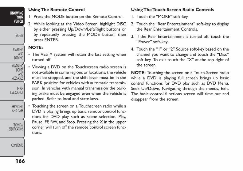
UsingThe Remote Control
1. Press the MODE button on the Remote Control.
2. While looking at the Video Screen, highlight DISCby either pressing Up/Down/Left/Right buttons orby repeatedly pressing the MODE button, thenpress ENTER.
NOTE:
• The VES™ system will retain the last setting whenturned off.
• Viewing a DVD on the Touchscreen radio screen isnot available in some regions or locations, the vehiclemust be stopped, and the shift lever must be in thePARK position for vehicles with automatic transmis-sion. In vehicles with manual transmission the park-ing brake must be engaged even when the vehicle isparked. Refer to local and state laws.
• Touching the screen on a Touchscreen radio while aDVD is playing brings up basic remote control func-tions for DVD play such as scene selection, Play,Pause, FF, RW, and Stop. Pressing the X in the uppercorner will turn off the remote control screen func-tions.
UsingTheTouch-Screen Radio Controls
1. Touch the “MORE” soft-key.
2. Touch the “Rear Entertainment” soft-key to displaythe Rear Entertainment Controls.
3. If the Rear Entertainment is turned off, touch the“Power” soft-key.
4. Touch the “1” or “2” Source soft-key based on thechannel you want to change and touch the “Disc”soft-key. To exit touch the “X” at the top right ofthe screen.
NOTE: Touching the screen on a Touch-Screen radiowhile a DVD is playing full screen brings up basiccontrol functions for DVD play such as DVD Menu,Seek Up/Down, Navigating through the menus, Exit.The basic control functions screen will time out anddisappear from the screen.
166
KNOWINGYOUR
VEHICLE
SAFETY
STARTINGAND
DRIVING
WARNINGLIGHTS
ANDMESSAGES
IN ANEMERGENCY
SERVICINGAND CARE
TECHNICALSPECIFICATIONS
CONTENTS

Remote Control OperationQuick Reference Chart
This chart provides a quick reference of the remotecontrol button functions for the different radio modesand menu screens.
NOTE:
• Ensure the remote control channel/screen selectorswitch is set to the screen or channel to be con-trolled.
• Ensure the headphone channel selector switch is setto the screen or channel to be listened to.
RemoteControl Button
Standard Screens Menu ScreensAM/FM/MW/LW
DISCAUX/AUX1/AUX2
ModeSelectMenu
ScreenSetup
Power Screen ON/OFFLight Remote Backlight ON/OFF
Up Arrow Next Seek Up*NextTrack
Audio: Next TrackNot Avail-
ableSelection
UpSelection
UpVideo Play: Next ChapterVideo Menu: Selection Up
Down ArrowPrev Seek Down*
PreviousTrack
Audio: Previous Track
Not Avail-able
SelectionDown
SelectionDown
Video Play: PreviousChapter
Video Menu: SelectionDown
Right Arrow FF Tune Up*Fast For-
ward
Audio: Fast ForwardNot Avail-
ableSelection
RightSelection
RightVideo Play: Fast ForwardVideo Menu: Selection
Right
167
KNOWINGYOURVEHICLE
SAFETY
STARTINGANDDRIVING
WARNINGLIGHTSANDMESSAGES
IN ANEMERGENCY
SERVICINGAND CARE
TECHNICALSPECIFICATIONS
CONTENTS
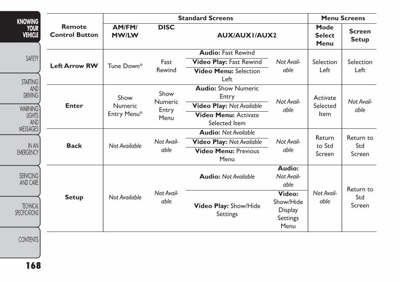
RemoteControl Button
Standard Screens Menu ScreensAM/FM/MW/LW
DISCAUX/AUX1/AUX2
ModeSelectMenu
ScreenSetup
Left Arrow RW Tune Down*Fast
Rewind
Audio: Fast RewindNot Avail-
ableSelection
LeftSelection
LeftVideo Play: Fast RewindVideo Menu: Selection
Left
EnterShow
NumericEntry Menu*
ShowNumeric
EntryMenu
Audio: Show NumericEntry
Not Avail-able
ActivateSelected
Item
Not Avail-able
Video Play: Not AvailableVideo Menu: Activate
Selected Item
Back Not AvailableNot Avail-
able
Audio: Not AvailableNot Avail-
able
Returnto StdScreen
Return toStd
Screen
Video Play: Not AvailableVideo Menu: Previous
Menu
Setup Not AvailableNot Avail-
able
Audio: Not AvailableAudio:Not Avail-
ableNot Avail-
able
Return toStd
ScreenVideo Play: Show/HideSettings
Video:Show/Hide
DisplaySettingsMenu
168
KNOWINGYOUR
VEHICLE
SAFETY
STARTINGAND
DRIVING
WARNINGLIGHTS
ANDMESSAGES
IN ANEMERGENCY
SERVICINGAND CARE
TECHNICALSPECIFICATIONS
CONTENTS

RemoteControl Button
Standard Screens Menu ScreensAM/FM/MW/LW
DISCAUX/AUX1/AUX2
ModeSelectMenu
ScreenSetup
Menu Not AvailableShow DiscOptionsMenu
Audio: Disc OptionsMenu Not Avail-
ableNot Avail-
ableNot Avail-
ableVideo Play: ShowDisc Menu
Play/Pause Not Available
Pause ifplaying,
elseresume
play
Audio: Pause ifplaying/resume
Not Avail-able
Not Avail-able
Not Avail-able
Video Play: Pause ifplaying/resume
Video Menu: Activateselected item
Stop Not Available Stop StopNot Avail-
ableNot Avail-
ableNot Avail-
ableMute Mute/Unmute Headphones
Slow Not AvailableNot Avail-
able
Audio: Not AvailableNot Avail-
ableNot Avail-
ableNot Avail-
ableVideo Play: Slow
play/resumeVideo Menu: Not Available
169
KNOWINGYOURVEHICLE
SAFETY
STARTINGANDDRIVING
WARNINGLIGHTSANDMESSAGES
IN ANEMERGENCY
SERVICINGAND CARE
TECHNICALSPECIFICATIONS
CONTENTS
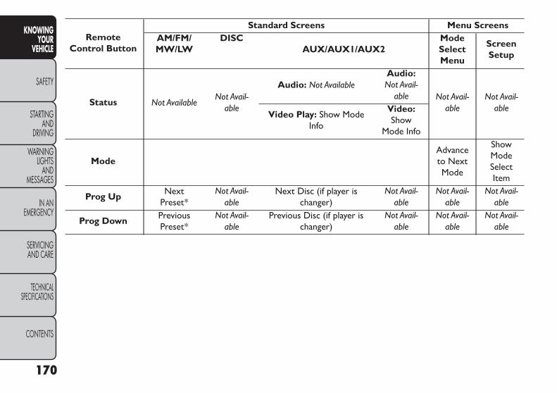
RemoteControl Button
Standard Screens Menu ScreensAM/FM/MW/LW
DISCAUX/AUX1/AUX2
ModeSelectMenu
ScreenSetup
Status Not AvailableNot Avail-
able
Audio: Not AvailableAudio:Not Avail-
able Not Avail-able
Not Avail-able
Video Play: Show ModeInfo
Video:Show
Mode Info
ModeAdvanceto NextMode
ShowModeSelectItem
Prog Up NextPreset*
Not Avail-able
Next Disc (if player ischanger)
Not Avail-able
Not Avail-able
Not Avail-able
Prog Down PreviousPreset*
Not Avail-able
Previous Disc (if player ischanger)
Not Avail-able
Not Avail-able
Not Avail-able
170
KNOWINGYOUR
VEHICLE
SAFETY
STARTINGAND
DRIVING
WARNINGLIGHTS
ANDMESSAGES
IN ANEMERGENCY
SERVICINGAND CARE
TECHNICALSPECIFICATIONS
CONTENTS
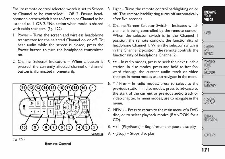
Ensure remote control selector switch is set to Screenor Channel to be controlled: 1 OR 2. Ensure head-phone selector switch is set to Screen or Channel to belistened to: 1 OR 2. *No action when mode is sharedwith cabin speakers. (fig. 122)
1. Power – Turns the screen and wireless headphonetransmitter for the selected Channel on or off. Tohear audio while the screen is closed, press thePower button to turn the headphone transmitteron.
2. Channel Selector Indicators – When a button ispressed, the currently affected channel or channelbutton is illuminated momentarily.
3. Light – Turns the remote control backlighting on oroff. The remote backlighting turns off automaticallyafter five seconds.
4. Channel/Screen Selector Switch - Indicates whichchannel is being controlled by the remote control.When the selector switch is in the Channel 1position, the remote controls the functionality ofheadphone Channel 1. When the selector switch isin the Channel 2 position, the remote controls thefunctionality of headphone Channel 2.
5. ▸▸ – In radio modes, press to seek the next tunablestation. In disc modes, press and hold to fast for-ward through the current audio track or videochapter. In menu modes use to navigate in the menu.
6. ▾ / Prev – In radio modes, press to select to theprevious station. In disc modes, press to advance tothe start of the current or previous audio track orvideo chapter. In menu modes, use to navigate in themenu.
7. MENU – Press to return to the main menu of a DVDdisc, or to select playback modes (RANDOM for aCD).
8. ▸ / || (Play/Pause) – Begin/resume or pause disc play.
9. ▪ (Stop) – Stops disc play(fig. 122)
Remote Control
171
KNOWINGYOURVEHICLE
SAFETY
STARTINGANDDRIVING
WARNINGLIGHTSANDMESSAGES
IN ANEMERGENCY
SERVICINGAND CARE
TECHNICALSPECIFICATIONS
CONTENTS

10. PROG Up/Down – When listening to a radiomode, pressing PROG Up selects the next presetand pressing PROG Down selects the previouspreset stored in the radio. When listening to com-pressed audio on a data disc, PROG Up selects thenext directory and PROG Down selects the pre-vious directory. When listening to a disc in a radiowith a multiple-disc changer, PROG Up selects thenext disc and PROG Down selects the previousdisc.
11. MUTE – Press to mute the headphone audio out-put for the selected channel.
12. SLOW – Press to slow playback of a DVD disc.Press play (▸) to resume normal play.
13. STATUS – Press to display the current status whilein a video mode display.
14. MODE – Press to change the mode of the selectedchannel. See the Mode Selection section of thismanual for details on changing modes.
15. SETUP – When in a video mode, press the SETUPbutton to access the display settings (see thedisplay settings section) to access the DVD setup
menu, select the menu button on the radio. Whena disc is loaded in the DVD player (for versions/markets, where provided) and the VES™ mode isselected and the disc is stopped, press the SETUPbutton to access the DVD Setup menu. (see theDVD Setup Menu of this manual.)
16. BACK – When navigating in menu mode, press toreturn to the previous screen. When navigating aDVDs disc menu, the operation depends on thedisc’s contents.
17. ◂◂ – In radio modes, press to seek to the previoustunable station. In disc modes, press and hold tofast rewind through the current audio track orvideo chapter. In menu modes use to navigate inthe menu.
18. ENTER – Press to select the highlighted option ina menu.
19. ▴ / NEXT – In radio modes, press to select to thenext station. In disc modes, press to advance tothe next audio track or video chapter. In menumodes, use to navigate in the menu.
172
KNOWINGYOUR
VEHICLE
SAFETY
STARTINGAND
DRIVING
WARNINGLIGHTS
ANDMESSAGES
IN ANEMERGENCY
SERVICINGAND CARE
TECHNICALSPECIFICATIONS
CONTENTS

Remote Control StorageThe video screen(s) come with a built in storagecompartment for the remote control which is acces-sible when the screen is opened. To remove the re-mote, use your index finger to pull and rotate theremote towards you. Do not try to pull the remotestraight down as it will be very difficult to remove. Toreturn the remote back into its storage area, insert onelong edge of the remote into the two retaining clipsfirst, and then rotate the remote back up into the othertwo retaining clips until it snaps back into position.(fig. 123)
LockingThe Remote ControlAll remote control functionality can be disabled as aparental control feature.
• To disable the Remote Control from making anychanges, press the Video Lock button and follow theradio’s instructions (select menu, rear ves, lock). Ifthe vehicle is not equipped with a DVD player, followthe radio’s instructions to turn Video Lock on. Theradio and the video screen(s) indicate when VideoLock is active.
• Pressing the Video Lock again or turning the ignitionOFF turns Video Lock OFF and allows remote con-trol operation of the VES™.
ReplacingThe Remote Control BatteriesThe remote control requires two AAA batteries foroperation. To replace the batteries:
• Locate the battery compartment on the back of theremote, then slide the battery cover downward.
• Replace the batteries, making sure to orient themaccording to the polarity diagram shown.
• Replace the battery compartment cover.
(fig. 123)The Remote Control Storage
173
KNOWINGYOURVEHICLE
SAFETY
STARTINGANDDRIVING
WARNINGLIGHTSANDMESSAGES
IN ANEMERGENCY
SERVICINGAND CARE
TECHNICALSPECIFICATIONS
CONTENTS

Headphones OperationThe headphones receive two separate channels ofaudio using an infrared transmitter from the videoscreen.
If no audio is heard after increasing the volume control,verify that the screen is turned on and in the downposition and that the channel is not muted and theheadphone channel selector switch is on the desiredchannel. If audio is still not heard, check that fullycharged batteries are installed in the headphones.(fig. 124)
ControlsThe headphone power indicator and controls are lo-cated on the right ear cup.
NOTE: The rear video system must be turned onbefore sound can be heard from the headphones. Toconserve battery life, the headphones will automati-cally turn off approximately three minutes after therear video system is turned off.
Changing the Audio Mode for Headphones
1. Ensure the Remote Control channel/screen selec-tor switch is in the same position as the headphoneselector switch.
NOTE:
• When both switches are on Channel 1, the Remoteis controlling Channel 1 and the headphones aretuned to the audio of the VES™ Channel 1.
• When both switches are on Channel 2, the Remoteis controlling Channel 2 and the headphones aretuned to the audio of the VES™ Channel 2.
2. Press the MODE button on the remote control.
(fig. 124)
1. Volume Control2. Power Button3. Channel Selection Switch4. Power Indicator
174
KNOWINGYOUR
VEHICLE
SAFETY
STARTINGAND
DRIVING
WARNINGLIGHTS
ANDMESSAGES
IN ANEMERGENCY
SERVICINGAND CARE
TECHNICALSPECIFICATIONS
CONTENTS

3. If the video screen is displaying a video source (suchas a DVD Video), pressing STATUS shows the statuson a popup banner at the bottom of the screen.Pressing the MODE button will advance to the nextmode. When the mode is in an audio only source(such as FM), the Mode Selection menu appears onscreen.
4. When the Mode Selection menu appears on screen,use the cursor buttons on the remote control tonavigate to the available modes and press the EN-TER button to select the new mode.
5. To cancel out of the Mode Selection menu, pressthe BACK button on the remote control.
ReplacingThe Headphone BatteriesEach set of headphones requires two AAA batteries foroperation. To replace the batteries:
• Locate the battery compartment on the left ear cupof the headphones, and then slide the battery coverdownward.
• Replace the batteries, making sure to orient themaccording to the polarity diagram shown.
• Replace the battery compartment cover.
Unwired® Stereo Headphone LifetimeLimited WarrantyWho Does This Warranty Cover? This warrantycovers the initial user or purchaser ("you" or "your") ofthis particular Unwired Technology LLC ("Unwired")wireless headphone ("Product"). The warranty is nottransferable.
How Long Does The Coverage Last? This war-ranty lasts as long as you own the Product.
What DoesThisWarranty Cover? Except as speci-fied below, this warranty covers any Product that innormal use is defective in workmanship or materials.
What DoesThis Warranty Not Cover? This war-ranty does not cover any damage or defect that resultsfrom misuse, abuse or modification of the Productother than by Unwired. Foam earpieces, which willwear over time through normal use, are specifically notcovered (replacement foam is available for a nominalcharge). UNWIRED TECHNOLOGY IS NOT LIABLEFOR ANY INJURIES OR DAMAGES TO PERSONSOR PROPERTY RESULTING FROM THE USE OF, ORANY FAILURE OR DEFECT IN, THE PRODUCT,NOR IS UNWIRED LIABLE FOR ANY GENERAL,SPECIAL, DIRECT, INDIRECT, INCIDENTAL, CON-SEQUENTIAL, EXEMPLARY, PUNITIVE OR OTHERDAMAGES OF ANY KIND OR NATURE WHATSO-EVER. Some states and jurisdictions may not allow the
175
KNOWINGYOURVEHICLE
SAFETY
STARTINGANDDRIVING
WARNINGLIGHTSANDMESSAGES
IN ANEMERGENCY
SERVICINGAND CARE
TECHNICALSPECIFICATIONS
CONTENTS

exclusion or limitation of incidental or consequentialdamages, so the above limitation may not apply to you.This warranty gives you specific legal rights. You mayalso have other rights, which vary from jurisdiction tojurisdiction.
WhatWill Unwired® Do? Unwired®, at its option,will repair or replace any defective Product. Unwired®reserves the right to replace any discontinued Productwith a comparable model. THIS WARRANTY IS THESOLE WARRANTY FOR THIS PRODUCT, SETSFORTH YOUR EXCLUSIVE REMEDY REGARDINGDEFECTIVE PRODUCTS, AND IS IN LIEU OF ALLOTHER WARRANTIES (EXPRESS OR IMPLIED), IN-CLUDING ANY WARRANTY OR MERCHANTABIL-ITY OR FITNESS FOR A PARTICULAR PURPOSE.
DisplayingVideoThe video screen has two different operating modes, avideo mode (when displaying video such as DVD video,Aux video, etc.) and an information mode as shown inFigure 116. Because the VES™ is a dual channel system,Information Mode is displayed in a split screen format.When in Information Mode, the left side of the screenis referred to as Channel 1 and the right side of thescreen is referred to as Channel 2.
Only Channel 1 displays video images. When in videomode the image is displayed on the full screen, howeverChannel 2’s functionality is still available. A popupbanner at the bottom of the screen is displayed mo-mentarily over the video image. While in video modeand Channel 2 is selected on the remote controlselector switch, the first remote control key press willactivate the popup banner indicating Channel 2’s sta-tus. While the banner is still visible, any subsequentremote control key press for Channel 2 shall initiatethe requested remote control command. (fig. 125)
(fig. 125)Popup Banner
176
KNOWINGYOUR
VEHICLE
SAFETY
STARTINGAND
DRIVING
WARNINGLIGHTS
ANDMESSAGES
IN ANEMERGENCY
SERVICINGAND CARE
TECHNICALSPECIFICATIONS
CONTENTS

In a two-screen system, the video for Channel 1 isdisplayed on the first rear seat screen and the video forChannel 2 is displayed on the second rear seat screen.Information Mode is displayed in split screen, the leftside of the screen (Channel 1) shows the status/modeof the first rear seat screen and the right side of thescreen (Channel 2) shows the status/mode of thesecond rear seat screen.
When Channel 1 is in a video mode, the image isdisplayed on the first rear seat screen as a full screenimage. A popup banner at the bottom of the screen isdisplayed momentarily over the video image showingany change in status of Channel 2.
When Channel 2 is in video mode, the image is dis-played on the second rear seat screen as a full screenimage. A popup banner at the bottom of the screen isdisplayed momentarily over the video image showingany change in status of Channel 1.
System Information
Information Mode DisplayWhen information mode is active, the current modesetting for both audio channels is displayed. In additionto the items called out by number, the remaininginformation displays the current status of the source(such as station frequency, name, preset or track num-ber, song title, artist name, album name, etc.).
• Channel 1 Mode – Displays the current source forChannel 1.
• Channel 1 Audio Only/Mute — Audio: The audioonly icon is not used on Channel 1, in a single screensystem. Mute: when the Mute icon is displayed, theaudio for Channel 1 has been muted using the re-mote control’s MUTE button.
• Channel 2 Audio Only/Mute — Audio: Only in asingle screen system: The audio only icon is displayedon Channel 2 when Channel 1 is in a video mode.Mute: when the Mute icon is displayed, the audio forChannel 2 has been muted using the remote con-trol’s MUTE button.
• Channel 2 Mode — Displays the current source forChannel 2.
• Channel 2 ENTER Button Action — When theENTER button on the remote control is pressedwith the "INPUT FILE #" button visible on thescreen, the screen shows a numeric entry keypadwhich allows you to enter a specific track number ondata discs and HDD (see Numeric Keypad Menusection of this manual). Also, Enter Button Action –“INPUT TRK #” to enter a specific track number onaudio discs.
• Remote Locked Out — When the icon is displayed,the remote control functions are disabled.
177
KNOWINGYOURVEHICLE
SAFETY
STARTINGANDDRIVING
WARNINGLIGHTSANDMESSAGES
IN ANEMERGENCY
SERVICINGAND CARE
TECHNICALSPECIFICATIONS
CONTENTS

• Clock — Displays the time.
• Channel 1 Shared Status — When the icon is dis-played, the audio for Channel 1 is also shared withthe radio and playing through the cabin speakers.
Numeric Keypad Menu(fig. 126)When the display for either Channel 1 or Channel 2shows DIRECT TUNE, pressing the remote control’sENTER button activates a numeric keypad menu. Thisscreen makes it easy to enter a specific tuner frequencyor track number. To enter the desired digit:
1. Press the remote control’s navigation buttons (▴, ▾,▸, ◂) to navigate to the desired digit.
2. When the digit is highlighted, press the remotecontrol’s ENTER button to select the digit. Repeatthese steps until all digits are entered.
3. To delete the last digit, navigate to the Del buttonand press the remote control’s ENTER button.
4. After all of the digits are entered, navigate to the Gobutton and press the remote control’s ENTER but-ton.
Disc MenuWhen listening to a CD Audio or CD Data disc,pressing the remote control’s MENU button displays alist of all commands which control playback of the disc.Using the options you can activate or cancel Randomplay.
(fig. 126)Numeric Keypad Menu
178
KNOWINGYOUR
VEHICLE
SAFETY
STARTINGAND
DRIVING
WARNINGLIGHTS
ANDMESSAGES
IN ANEMERGENCY
SERVICINGAND CARE
TECHNICALSPECIFICATIONS
CONTENTS

Options Menu(fig. 127)When watching a video source (DVD Video with thedisc in Play mode, Aux Video, etc.), pressing the “Op-tions” soft-key activates the Options Settings menu.From this menu you can adjust Audio, Subtitles, Angleand Title.
Display SettingsWhen watching a video source (DVD Video with thedisc in Play mode, Aux Video, etc.), pressing the re-mote control’s SETUP button activates the DisplaySettings menu. These settings control the appearanceof the video on the screen. The factory default settingsare already set for optimum viewing, so there is noneed to change these settings under normal circum-stances.
To change the settings, press the remote control’snavigation buttons to select an item, then press theremote control’s navigation buttons to change thevalue for the currently selected item. To reset all valuesback to the original settings, select the Default Settingsmenu option and press the remote control’s ENTERbutton.
(fig. 127)
179
KNOWINGYOURVEHICLE
SAFETY
STARTINGANDDRIVING
WARNINGLIGHTSANDMESSAGES
IN ANEMERGENCY
SERVICINGAND CARE
TECHNICALSPECIFICATIONS
CONTENTS
ListeningTo Audio WithThe Screen ClosedTo listen to only audio portion of the channel with thescreen closed:
• Set the audio to the desired source and channel.
• Close the video screen.
• To change the current audio mode, press the remotecontrol’s MODE button. This will automatically se-lect the next available audio mode without using theMODE/SOURCE Select menu.
If the screen is closed and there is no audio heard,verify that the headphones are turned on (the ONindicator is illuminated) and the headphone selectorswitch is on the desired channel. If the headphones areturned on, press the remote control’s power button toturn audio on. If audio is still not heard, check that fullycharged batteries are installed in the headphones.
Disc FormatsThe DVD player is capable of playing the followingtypes of discs (12 cm or 8 cm diameter):
• DVD-Video discs (MPEG-2 video compression) (seenotes about DVD Region Codes)
• Audio Compact Discs (CDs)
• CD Data discs with MP3 and WMA compressedaudio format files
• Video CDs (MPEG-1 video compression)
DVD Region Codes
The DVD player and many DVD discs are coded bygeographic region. These region codes must match inorder for the disc to play. If the region code for theDVD disc does not match the region code for theplayer, the disc will stop playing and a warning will bedisplayed.
DVD Audio Support
When a DVD-Audio disc is inserted in the DVD player,the DVD-Audio title on the disc is played by default(most DVD-Audio discs also have a Video title, but theVideo title is ignored). All multi-channel program ma-terial is automatically mixed down to two channels,which may result in a lowered apparent volume level.If you increase the volume level to account for thischange in level, remember to lower the volume beforechanging the disc or to another mode.
Recorded Discs
The DVD player will play CD-R and CD-RW discsrecorded in CD-Audio or Video-CD format, or as aCD-ROM containing MP3 or WMA files. The playerwill also play DVD-Video content recorded to aDVD-R, DVD-RW and DVD-ROM discs.
If you record a disc using a personal computer, theremay be cases where the DVD player may not be able toplay some or the entire disc, even if it is recorded in a
180
KNOWINGYOUR
VEHICLE
SAFETY
STARTINGAND
DRIVING
WARNINGLIGHTS
ANDMESSAGES
IN ANEMERGENCY
SERVICINGAND CARE
TECHNICALSPECIFICATIONS
CONTENTS

compatible format and is playable on other players. Tohelp avoid playback problems, use the following guide-lines when recording discs.
• Open sessions are ignored. Only sessions that areclosed are playable.
• For multi-session CDs that contain only multipleCD-Audio sessions, the player will renumber thetracks so each track number is unique.
• For CD Data (or CD-ROM) discs, always use theISO-9660 (Level 1 or Level 2), Joliet, or UDF format.CD-DA may also be used for PCM Audio containedon CD-Based Data.
• The player recognizes a maximum of 512 files and 99folders per CD-R and CD-RW disc.
• Mixed media recordable DVD formats will only playthe Video_TS portion of the disc.
If you are still having trouble writing a disc that isplayable in the DVD player, check with the disc record-ing software publisher for more information aboutburning playable discs.
The recommended method for labeling recordablediscs (CD-R, CD-RW, DVD-R and DVD-RW) is with apermanent marker. Do not use adhesive labels as theymay separate from the disc, become stuck, and causepermanent damage to the DVD player.
Compressed Audio Files (MP3,WMA ANDACC)
The DVD player is capable of playing MP3 (MPEG-1Audio Layer 3 with data bitrates from 32 to 320 kbit/s,including variable bit rates), WMA (All Standard 8.x,9.x Windows Media Audio) and ACC (MPEG-4 audio;sampling frequencies 8 to 48 kHz; mono and stereo)audio files with the from a CD Data disc (usually aCD-R or CD-RW).
• The DVD player always uses the file extension todetermine the audio format, so MP3 files must alwaysend with the extension ".mp3" or ".MP3", WMA filesmust always end with the extension ".wma" or"WMA", and ACC files must end with the extensions“.acc” or “.m4a”. To prevent incorrect playback, donot use these extensions for any other types of files.
• For MP3 files, ID3 tag data v1, v1.1, v2 and v2.4 (suchas artist name, track title, album, etc.) are supported.
• Any file that is copy protected (such as those down-loaded from many online music stores) will not play.The DVD player will automatically skip the file andbegin playing the next available file.
• Other compression formats such as AAC, MP3 Pro,Ogg Vorbis, and ATRAC3 will not play. The DVDplayer will automatically skip the file and begin playingthe next available file.
181
KNOWINGYOURVEHICLE
SAFETY
STARTINGANDDRIVING
WARNINGLIGHTSANDMESSAGES
IN ANEMERGENCY
SERVICINGAND CARE
TECHNICALSPECIFICATIONS
CONTENTS

• If you are creating your own files, the recommendedfixed bit rate for MP3 files is between 96 and192Kbps and the recommended fixed bit rate forWMA files is between 64 and 192Kbps. Variable bitrates are also supported. For both formats, therecommended sample rate is either 44.1kHz or48kHz.
• To change the current file, use the remote control’sor DVD player’s ▴ button to advance to the next file,or the ▾ button to return to the start of the currentor previous file.
• To change the current directory, use the remotecontrol’s PROG UP and Down buttons or Rewind/skip back and fast fwd/skip forward.
Disc Errors
If the DVD player is unable to read the disc, a "DiscError" message is displayed on the Radio display andthe disc is automatically ejected. A dirty, damaged, orincompatible disc format are all potential causes for a"Disc Error" message.
If a disc has a damaged track which results in audible orvisible errors that persists for 2.0 seconds, the DVDplayer will attempt to continue playing the disc byskipping forward 1.0 to 3.0 seconds at a time. If the endof the disc is reached, the DVD player will return to thebeginning of the disc and attempt to play the start ofthe first track.
The DVD player may shut down during extremely hotconditions, such as when the vehicle’s interior tem-perature is above 120°F. When this occurs, the DVDplayer will display "High Temp" and will shut off thedisplay until a safe temperature is reached. This shut-down is necessary to protect the optics of the DVDplayer.
182
KNOWINGYOUR
VEHICLE
SAFETY
STARTINGAND
DRIVING
WARNINGLIGHTS
ANDMESSAGES
IN ANEMERGENCY
SERVICINGAND CARE
TECHNICALSPECIFICATIONS
CONTENTS

Product AgreementThis product incorporates copyright protection tech-nology that is protected by U.S. patents and otherintellectual property rights. Use of this copyright pro-tection technology must be authorized by Macrovision,and is intended for home or other limited viewing usesotherwise authorized by Macrovision. Reverse engi-neering or disassembly is prohibited.
Dolby® Digital and MLP Lossless Manufacturedunder license from Dolby Laboratories. "Dolby", "MLPLossless", and the double-D symbol are trademarks ofDolby Laboratories. Confidential unpublished works.Copyright 1992-1997 Dolby Laboratories. All rightsreserved.
General Information
This system complies with Part 15 of the FCC Opera-tion is subject to the following two conditions:
1. This device may not cause harmful interference.
2. This device must accept any interference received,including interference that may cause undesiredoperation.
iPod®/USB/MP3 CONTROL(for versions/markets, whereprovided)This feature allows an iPod® or external USB device tobe plugged into the USB port.
iPod® control supports Mini, 4G, Photo, Nano, 5GiPod® and iPhone® devices. Some iPod® softwareversions may not fully support the iPod® controlfeatures. Please visit Apple’s website for software up-dates.
For further information, refer to the Uconnect® User’sManual.
183
KNOWINGYOURVEHICLE
SAFETY
STARTINGANDDRIVING
WARNINGLIGHTSANDMESSAGES
IN ANEMERGENCY
SERVICINGAND CARE
TECHNICALSPECIFICATIONS
CONTENTS

CD/DVD DISC MAINTENANCETo keep a CD/DVD in good condition, take the follow-ing precautions:
1. Handle the disc by its edge; avoid touching thesurface.
2. If the disc is stained, clean the surface with a softcloth, wiping from center to edge.
3. Do not apply paper or tape to the disc; avoidscratching the disc.
4. Do not use solvents such as benzene, thinner, clean-ers, or anti-static sprays.
5. Store the disc in its case after playing.
6. Do not expose the disc to direct sunlight.
7. Do not store the disc where temperatures maybecome too high.
NOTE: If you experience difficulty in playing a particu-lar disc, it may be damaged (i.e., scratched, reflectivecoating removed, a hair, moisture or dew on the disc)oversized, or have protection encoding. Try a knowngood disc before considering disc player service.
RADIO OPERATION AND MOBILEPHONESUnder certain conditions, the mobile phone being on inyour vehicle can cause erratic or noisy performancefrom your radio. This condition may be lessened oreliminated by relocating the mobile phone antenna.This condition is not harmful to the radio. If your radioperformance does not satisfactorily “clear” by therepositioning of the antenna, it is recommended thatthe radio volume be turned down or off during mobilephone operation.
184
KNOWINGYOUR
VEHICLE
SAFETY
STARTINGAND
DRIVING
WARNINGLIGHTS
ANDMESSAGES
IN ANEMERGENCY
SERVICINGAND CARE
TECHNICALSPECIFICATIONS
CONTENTS
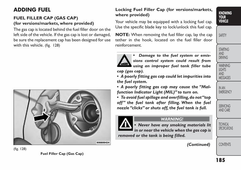
ADDING FUELFUEL FILLER CAP (GAS CAP)(for versions/markets, where provided)The gas cap is located behind the fuel filler door on theleft side of the vehicle. If the gas cap is lost or damaged,be sure the replacement cap has been designed for usewith this vehicle. (fig. 128)
Locking Fuel Filler Cap (for versions/markets,where provided)
Your vehicle may be equipped with a locking fuel cap.Use the specific blade key to lock/unlock this fuel cap.
NOTE: When removing the fuel filler cap, lay the captether in the hook, located on the fuel filler doorreinforcement.
• Damage to the fuel system or emis-sions control system could result fromusing an improper fuel tank filler tube
cap (gas cap).• A poorly fitting gas cap could let impurities intothe fuel system.• A poorly fitting gas cap may cause the “Mal-function Indicator Light (MIL)” to turn on.• To avoid fuel spillage and overfilling,do not“topoff” the fuel tank after filling. When the fuelnozzle “clicks” or shuts off, the fuel tank is full.
WARNING!• Never have any smoking materials litin or near the vehicle when the gas cap is
removed or the tank is being filled.
(Continued)(fig. 128)
Fuel Filler Cap (Gas Cap)
185
KNOWINGYOURVEHICLE
SAFETY
STARTINGANDDRIVING
WARNINGLIGHTSANDMESSAGES
IN ANEMERGENCY
SERVICINGAND CARE
TECHNICALSPECIFICATIONS
CONTENTS

(Continued)• Never add fuel to the vehicle when the engine isrunning.• A fire may result if gasoline is pumped into aportable container that is inside of a vehicle.Youcould be burned.Always place gas containers onthe ground while filling.• Failure to follow this warning may result inserious injury or death.
NOTE:
• When the fuel nozzle “clicks” or shuts off, the fueltank is full.
• Tighten the gas cap until you hear a “clicking” sound.This is an indication that the gas cap is tightenedproperly. The MIL in the instrument cluster may turnon if the gas cap is not secured properly. Make surethat the gas cap is tightened each time the vehicle isrefueled.
LOOSE FUEL FILLER CAP MESSAGE(for versions/markets, where provided)If the vehicle diagnostic system determines that thefuel filler cap is loose, improperly installed, or damaged,a “Check Gascap” message will display in the ElectronicVehicle Information Center (EVIC). If this occurs,tighten the fuel filler cap properly and press the TRIPODOMETER button to turn off the message. If theproblem continues, the message will appear the nexttime the vehicle is started.
186
KNOWINGYOUR
VEHICLE
SAFETY
STARTINGAND
DRIVING
WARNINGLIGHTS
ANDMESSAGES
IN ANEMERGENCY
SERVICINGAND CARE
TECHNICALSPECIFICATIONS
CONTENTS

SAFETYOCCUPANT RESTRAINTSSome of the most important safety features in yourvehicle are the restraint systems:
• Three-point lap and shoulder belts for all seatingpositions
• Advanced Front Air Bags for driver and front passenger
• Supplemental Active Head Restraints (AHR) locatedon top of the front seats (integrated into the headrestraint) (for versions/markets, where provided)
• Supplemental Side Air Bag Inflatable Curtains(SABIC) that span the front, second, and third rowseating for the driver and passengers seated next toa window
• Supplemental Seat-Mounted Side Air Bags
• An energy-absorbing steering column and steeringwheel
• Knee bolsters/blockers for front seat occupants
• Front seat belts incorporate pretensioners that mayenhance occupant protection by managing occupantenergy during an impact event
If you will be carrying children too small for adult-sizedseat belts, the seat belts or ISOFIX feature also canbe used to hold infant and child restraint systems.
For more information, refer to ISOFIX — Child SeatAnchorage System.
NOTE: The Advanced Front Air Bags have a multi-stage inflator design. This allows the air bag to havedifferent rates of inflation based on several factors,including the severity and type of collision.
Please pay close attention to the information in thissection. It tells you how to use your restraint systemproperly, to keep you and your passengers as safe aspossible.
WARNING!In a collision, you and your passengerscan suffer much greater injuries if you
are not properly buckled up.You can strike theinterior of your vehicle or other passengers, oryou can be thrown out of the vehicle.Always besure you and others in your vehicle are buckledup properly.
Buckle up even though you are an excellent driver, evenon short trips. Someone on the road may be a poordriver and cause a collision that includes you. This canhappen far away from home or on your own street.
187
KNOWINGYOURVEHICLE
SAFETY
STARTINGANDDRIVING
WARNINGLIGHTSANDMESSAGES
IN ANEMERGENCY
SERVICINGAND CARE
TECHNICALSPECIFICATIONS
CONTENTS

Research has shown that seat belts save lives, and theycan reduce the seriousness of injuries in a collision.Some of the worst injuries happen when people arethrown from the vehicle. Seat belts reduce the possi-bility of ejection and the risk of injury caused by strikingthe inside of the vehicle. Everyone in a motor vehicleshould be belted at all times.
Lap/Shoulder BeltsAll seating positions in your vehicle are equipped witha combination lap/shoulder belt.
The belt webbing retractor is designed to lock duringvery sudden stops or impacts. This feature allows theshoulder part of the belt to move freely with you undernormal conditions. However, in a collision, the belt willlock and reduce your risk of striking the inside of thevehicle or being thrown out.
WARNING!• It is dangerous to ride in a cargo area,inside or outside of a vehicle. In a colli-
sion, people riding in these areas are more likelyto be seriously injured or killed.• Do not allow people to ride in any area of yourvehicle that is not equipped with seats and seatbelts.
(Continued)
(Continued)• Be sure everyone in your vehicle is in a seat andusing a seat belt properly.• Wearing a seat belt incorrectly is dangerous.Seat belts are designed to go around the largebones of your body.These are the strongest partsof your body and can take the forces of a collisionthe best. Wearing your belt in the wrong placecould make your injuries in a collision muchworse.You might suffer internal injuries, or youcould even slide out of part of the belt. Followthese instructions to wear your seat belt safelyand to keep your passengers safe, too.• Two people should never be belted into a singleseat belt. People belted together can crash intoone another in a collision, hurting one anotherbadly. Never use a lap/shoulder belt or a lap beltfor more than one person, no matter what theirsize.
188
KNOWINGYOUR
VEHICLE
SAFETY
STARTINGAND
DRIVING
WARNINGLIGHTS
ANDMESSAGES
IN ANEMERGENCY
SERVICINGAND CARE
TECHNICALSPECIFICATIONS
CONTENTS

Lap/Shoulder Belt Operating Instructions
1. Enter the vehicle and close the door. Sit back andadjust the front seat.
2. The seat belt latch plate is along side the pillar nearthe back of your seat. Grasp the latch plate and pullout the belt. Slide the latch plate up the webbing asfar as necessary to make the belt go around your lap.(fig. 129)
3. When the belt is long enough to fit, insert the latchplate into the buckle until you hear a “click.”(fig. 130)
(fig. 129)Pulling Out Lap/Shoulder Belt
(fig. 130)Connecting Latch PlateTo Buckle
189
KNOWINGYOURVEHICLE
SAFETY
STARTINGANDDRIVING
WARNINGLIGHTSANDMESSAGES
IN ANEMERGENCY
SERVICINGAND CARE
TECHNICALSPECIFICATIONS
CONTENTS

WARNING!• A belt that is buckled into the wrongbuckle will not protect you properly.The
lap portion could ride too high on your body,possibly causing internal injuries. Always buckleyour belt into the buckle nearest you.• A belt that is too loose will not protect youproperly. In a sudden stop you could move too farforward, increasing the possibility of injury.Wearyour seat belt snugly.• A belt that is worn under your arm is danger-ous.Your body could strike the inside surfaces ofthe vehicle in a collision, increasing head andneck injury.A belt worn under the arm can causeinternal injuries.Ribs aren't as strong as shoulderbones.Wear the belt over your shoulder so thatyour strongest bones will take the force in acollision.• A shoulder belt placed behind you will notprotect you from injury during a collision.You aremore likely to hit your head in a collision if you donot wear your shoulder belt.The lap and shoulderbelt are meant to be used together.
4. Position the lap belt across your thighs, below yourabdomen. To remove slack in the lap belt portion,pull up a bit on the shoulder belt. To loosen the lapbelt if it is too tight, tilt the latch plate and pull onthe lap belt. A snug belt reduces the risk of slidingunder the belt in a collision. (fig. 131)
(fig. 131)Removing Slack From Belt
190
KNOWINGYOUR
VEHICLE
SAFETY
STARTINGAND
DRIVING
WARNINGLIGHTS
ANDMESSAGES
IN ANEMERGENCY
SERVICINGAND CARE
TECHNICALSPECIFICATIONS
CONTENTS

WARNING!• A lap belt worn too high can increasethe risk of internal injury in a collision.
The belt forces won't be at the strong hip andpelvic bones, but across your abdomen. Alwayswear the lap belt as low as possible and keep itsnug.• A twisted belt may not protect you properly. Ina collision, it could even cut into you. Be sure thebelt is straight. If you can't straighten a belt inyour vehicle, take it to your authorized dealerimmediately and have it fixed.
5. Position the shoulder belt on your chest so that it iscomfortable and not resting on your neck. Theretractor will withdraw any slack in the belt.
6. To release the belt, push the red button on thebuckle. The belt will automatically retract to itsstowed position. If necessary, slide the latch platedown the webbing to allow the belt to retract fully.
WARNING!A frayed or torn belt could rip apart in acollision and leave you with no protec-
tion. Inspect the belt system periodically, check-ing for cuts, frays, or loose parts. Damaged parts
(Continued)
(Continued)must be replaced immediately. Do not disas-semble or modify the system. Seat belt assem-blies must be replaced after a collision if theyhave been damaged (bent retractor, torn web-bing, etc.).
Adjustable Upper Shoulder Belt AnchorageIn the driver's seat and front passenger's seat, theshoulder belt can be adjusted upward or downward toposition the belt away from your neck. Push and fullydepress the button above the webbing to release theanchorage, then move it up or down to the positionthat fits you best. (fig. 132)
(fig. 132)Adjusting Upper Shoulder Belt
191
KNOWINGYOURVEHICLE
SAFETY
STARTINGANDDRIVING
WARNINGLIGHTSANDMESSAGES
IN ANEMERGENCY
SERVICINGAND CARE
TECHNICALSPECIFICATIONS
CONTENTS

As a guide, if you are shorter than average you willprefer a lower position and if you are taller thanaverage you will prefer a higher position. When yourelease the anchorage try to move it up and down tomake sure that it is locked in position.
In the rear seat, move toward the center of the seat toposition the belt away from your neck.
Lap/Shoulder Belt Untwisting ProcedureUse the following procedure to untwist a twistedlap/shoulder belt:
1. Position the latch plate as close as possible to theanchor point.
2. At about 15 to 30 cm above the latch plate, graspand twist the belt webbing 180 degrees to create afold that begins immediately above the latch plate.
3. Slide the latch plate upward over the folded web-bing. The folded webbing must enter the slot at thetop of the latch plate.
4. Continue to slide the latch plate up until it clears thefolded webbing.
SEAT BELT PRETENSIONERSThe seat belts for both front seating positions areequipped with pretensioning devices that are designedto remove slack from the seat belt in the event of acollision. These devices may improve the performance
of the seat belt by assuring that the belt is tight aboutthe occupant early in a collision. Pretensioners workfor all size occupants, including those in child restraints.
NOTE: These devices are not a substitute for properseat belt placement by the occupant. The seat belt stillmust be worn snugly and positioned properly.
The pretensioners are triggered by the Occupant Re-straint Controller (ORC). Like the air bags, the preten-sioners are single use items. A deployed pretensioneror a deployed air bag must be replaced immediately.
Supplemental Active Head Restraints (AHR)These head restraints are passive, deployable compo-nents, and vehicles with this equipment cannot bereadily identified by any markings, only through visualinspection of the head restraint. The head restraint willbe split in two halves, with the front half being softfoam and trim, the back half being decorative plastic.
HowThe Active Head Restraints (AHR) Work
The Occupant Restraint Controller (ORC) determineswhether the severity, or type of rear impact will requirethe Active Head Restraints (AHR) to deploy. If a rearimpact requires deployment, both the driver and frontpassenger seat AHRs will be deployed.
When AHRs deploy during a rear impact, the front halfof the head restraint extends forward to minimize thegap between the back of the occupant’s head and the
192
KNOWINGYOUR
VEHICLE
SAFETY
STARTINGAND
DRIVING
WARNINGLIGHTS
ANDMESSAGES
IN ANEMERGENCY
SERVICINGAND CARE
TECHNICALSPECIFICATIONS
CONTENTS

AHR. This system is designed to help prevent orreduce the extent of injuries to the driver and frontpassenger in certain types of rear impacts.
NOTE: The Active Head Restraints (AHR) may ormay not deploy in the event of a front or side impact.However if during a front impact, a secondary rearimpact occurs, the AHR may deploy based on severalfactors, including the severity and type of the impact.(fig. 133)
All occupants, including the driver, shouldnot operate a vehicle or sit in a vehicle'sseat until the head restraints are placed
in their proper positions in order to minimize therisk of neck injury in the event of a collision.
NOTE: For more information on properly adjustingand positioning the head restraint, refer to “AdjustingActive Head Restraints” in “Knowing Your Vehicle”.
(fig. 133)Active Head Restraint (AHR) Components
1 — Head Restraint FrontHalf (Soft Foam and Trim)
3 — Head Restraint BackHalf (Decorative Plastic RearCover)2 — Seatback4 — Head Restraint GuideTubes
193
KNOWINGYOURVEHICLE
SAFETY
STARTINGANDDRIVING
WARNINGLIGHTSANDMESSAGES
IN ANEMERGENCY
SERVICINGAND CARE
TECHNICALSPECIFICATIONS
CONTENTS

Resetting Active Head Restraints (AHR)If the Active Head Restraints are triggered in a collision,you must reset the head restraint on the driver’s andfront passenger seat. You can recognize when theActive Head Restraint has been triggered by the factthat they have moved forward (as shown in step threeof the resetting procedure).
1. Grasp the deployed AHR from the rear seat.(fig. 134)
2. Position the hands on the top of the deployed AHRat a comfortable position.
3. Pull down then rearward towards the rear of thevehicle then down to engage the locking mecha-nism. (fig. 135) (fig. 136)
(fig. 134)Hand Positioning Points On AHR
(fig. 135)
1 — Downward Movement2 — Rearward Movement
194
KNOWINGYOUR
VEHICLE
SAFETY
STARTINGAND
DRIVING
WARNINGLIGHTS
ANDMESSAGES
IN ANEMERGENCY
SERVICINGAND CARE
TECHNICALSPECIFICATIONS
CONTENTS

4. The AHR front soft foam and trim half should lockinto the back decorative plastic half. (fig. 137)
NOTE:
• If you have difficulties or problems resetting theActive Head Restraints, see an authorized dealer.
• For safety reasons, have the Active Head Restraintschecked by a qualified specialist at an authorizeddealer.
ACTIVE HOOD SYSTEM (for versions/markets, where provided)The Active Hood system is intended to enhance pe-destrian protection by elevating the vehicle’s hoodupon an impact with a pedestrian or other object. Thesystem is automatically activated when the vehicle ismoving within a specified vehicle speed range. In orderto detect a range of pedestrians, other objects that areimpacted may result in an Active Hood deployment.
Deployment Sensors And ControlsThe Electronic Pedestrian Protection Module (EPPM)determines if deployment of the actuators in a frontalimpact is required. Based on the impact sensors signals,the EPPM determines when to deploy the actuators.
(fig. 136)
3 — Final Downward Movement To Engage LockingMechanism (fig. 137)
AHR In Reset Position
195
KNOWINGYOURVEHICLE
SAFETY
STARTINGANDDRIVING
WARNINGLIGHTSANDMESSAGES
IN ANEMERGENCY
SERVICINGAND CARE
TECHNICALSPECIFICATIONS
CONTENTS

The impact sensors are located within the front bum-per area.
The EPPM monitors the readiness of the electronicparts of the Active Hood system whenever the ignitionswitch is in the START or ON/RUN position. If the keyis in the LOCK position, in the ACC position, or not inthe ignition, the Active Hood system is not on and theActive Hood will not deploy.
The EPPM contains a backup power supply system thatmay deploy the actuators even if the battery losespower or it becomes disconnected prior to deploy-ment.
Service Active Hood SystemIf the EPPM has deployed the Active Hood, or if itdetects a malfunction in any part of the system, it turnson the Air Bag Warning Light and it will display the“SERVICE ACTIVE HOOD” message in the ElectronicVehicle Information Center (EVIC), for versions/markets, where provided. A single chime will sound ifthe Air Bag Warning Light comes on again after initialstartup. It also includes diagnostics that will illuminatethe Air Bag Warning Light if a malfunction is noted thatcould affect the Active Hood system. The diagnosticsalso record the nature of the malfunction. If the Air BagWarning Light is illuminated, or if “SERVICE ACTIVEHOOD” appears in the EVIC, see your authorizeddealer.
In the event of an Active Hood deployment, the vehicleshould be serviced by an authorized dealer. The hoodhinges must be serviced and the actuator assembliesreplaced to restore system functionality.
Following an Active Hood deployment, the hood posi-tion can be temporarily reset by pushing down at therear edge over the hood hinges as the internal pressureof each actuator is relieved. The temporary hood resetposition is intended to improve forward driving visibil-ity over the hood until the vehicle can be serviced. Thetemporary hood reset position will leave the hoodapproximately 5 mm above the fender surface. (fig. 138)
(fig. 138)Temporary Hood Reset Position
196
KNOWINGYOUR
VEHICLE
SAFETY
STARTINGAND
DRIVING
WARNINGLIGHTS
ANDMESSAGES
IN ANEMERGENCY
SERVICINGAND CARE
TECHNICALSPECIFICATIONS
CONTENTS
The front bumper assembly may affect proper opera-tion of the Active Hood system. The front bumpercomponents should be inspected for damage and re-placed if necessary in the event of a frontal impact, evenif it occurs at a low rate of speed.
NOTE: After any Active Hood deployment, the ve-hicle should be taken to an authorized dealer immedi-ately.
To prevent possible damage, do not slamthe rear of the hood to reset it. Press therear of the hood down until an audible
and tactile detent is detected (approximately 5 mmabove the fender). This should secure both hoodhinge reset mechanisms.
WARNING!• Ignoring the Air Bag Warning Light inyour instrument panel or the “SERVICE
ACTIVE HOOD” message in the EVIC could meanyou won’t have theActive Hood to enhance pedes-trian protection. If the light does not come on as abulb check when the ignition is first turned on,stays on after you start the vehicle, or if it comeson as you drive, see your authorized dealer.
(Continued)
(Continued)• Modifications to any part of the Active Hoodsystem could cause it to fail when you need it.Donot modify the components or wiring. Do notmodify the front bumper, vehicle body structure,or add an aftermarket front bumper or cover.• It is dangerous to try to repair any part of theActive Hood system yourself. Be sure to tell any-one who works on your vehicle that it has anActive Hood system.• Do not attempt to modify any part of yourActive Hood system.TheActive Hood may deployaccidentally or may not function properly ifmodifications are made.Take your vehicle to anauthorized dealer for any hood service.• Drivers must be aware of pedestrians. Alwaysbe sure to check for pedestrians, animals, othervehicles,and obstructions.You are responsible forsafety and must continue to pay attention toyour surroundings. Failure to do so can result inserious injury or death.
197
KNOWINGYOURVEHICLE
SAFETY
STARTINGANDDRIVING
WARNINGLIGHTSANDMESSAGES
IN ANEMERGENCY
SERVICINGAND CARE
TECHNICALSPECIFICATIONS
CONTENTS

Enhanced Seat Belt Use Reminder System(BeltAlert®)BeltAlert® is a feature intended to remind the driverand front passenger (for versions/markets, where pro-vided with front passenger BeltAlert®) to fasten theirseatbelts. The feature is active whenever the ignition ison. If the driver or front seat passenger is unbelted, theSeat Belt Reminder Light will turn on and remain onuntil both front seatbelts are fastened.
The BeltAlert® warning sequence begins after thevehicle speed is over 8 km/h, by blinking the Seat BeltReminder Light and sounding an intermittent chime.Once the sequence starts, it will continue for theentire duration or until the respective seatbelts arefastened. After the sequence completes, the SeatbeltReminder Light remains illuminated until the respectiveseatbelts are fastened. The driver should instruct allother occupants to fasten their seatbelts. If a frontseatbelt is unbuckled while traveling at speeds greaterthan 8 km/h, BeltAlert® will provide both audio andvisual notification.
The front passenger seat BeltAlert® is not active whenthe front passenger seat is unoccupied. BeltAlert® maybe triggered when an animal or heavy object is on the
front passenger seat or when the seat is folded flat (forversions/markets, where provided). It is recommendedthat pets be restrained in the rear seat in pet harnessesor pet carriers that are secured by seat belts, and cargois properly stowed.
BeltAlert® can be enabled or disabled by your autho-rized dealer.
NOTE: Although BeltAlert® has been deactivated,the Seat Belt Reminder Light will continue to illuminatewhile the driver’s or front passenger (for versions/markets, where provided with BeltAlert®) seat beltremains unfastened.
Seat Belts And Pregnant WomenWe recommend that pregnant women use the seatbelts throughout their pregnancy. Keeping the mothersafe is the best way to keep the baby safe.
Pregnant women should wear the lap part of the beltacross the thighs and as snug across the hips as pos-sible. Keep the belt low so that it does not come acrossthe abdomen. That way the strong bones of the hipswill take the force if there is a collision.
198
KNOWINGYOUR
VEHICLE
SAFETY
STARTINGAND
DRIVING
WARNINGLIGHTS
ANDMESSAGES
IN ANEMERGENCY
SERVICINGAND CARE
TECHNICALSPECIFICATIONS
CONTENTS

Child Restraints(fig. 139)Everyone in your vehicle needs to be buckled up at alltimes, including babies and children.
Children 12 years or younger should ride properlybuckled up in a rear seat, if available. According to crashstatistics, children are safer when properly restrainedin the rear seats rather than in the front.
There are different sizes and types of restraints forchildren from newborn size to the child almost largeenough for an adult safety belt. Always check the childseat Owner’s Manual to make sure you have the cor-rect seat for your child.
Before buying any restraint system, make sure that ithas a label certifying that it meets all applicable SafetyStandards. You should also make sure that you caninstall it in the vehicle where you will use it.
WARNING!• “Extreme Hazard! Do not use arearward-facing child restraint on a seat
protected by an air bag in front of it!” Refer tovisor and door shut face mounted labels for infor-mation.• In a collision, an unrestrained child, even a tinybaby, can become a projectile inside the vehicle.The force required to hold even an infant on yourlap could become so great that you could nothold the child, no matter how strong you are.The child and others could be badly injured.Anychild riding in your vehicle should be in a properrestraint for the child's size.
(fig. 139)
199
KNOWINGYOURVEHICLE
SAFETY
STARTINGANDDRIVING
WARNINGLIGHTSANDMESSAGES
IN ANEMERGENCY
SERVICINGAND CARE
TECHNICALSPECIFICATIONS
CONTENTS

Mass GroupSeating Position (or other site)
Front Passenger Rear Outboard Rear CenterIntermediate
OutboardIntermediate
CenterGroup —
up to 10 kgX *U N/A **U U
Group 0+ —up to 13 kg
X *U N/A **U U
Group 1 –9 to 18 kg
X *U N/A **U U
Group II –15 to 25 kg
X *U N/A **U U
Group III —22 to 36 kg
X *U N/A **U U
Key of letters used in the table above:
• U = Suitable for “universal” category restraints ap-proved for use in this mass group.
• X = Seat position not suitable for children in thismass group.
200
KNOWINGYOUR
VEHICLE
SAFETY
STARTINGAND
DRIVING
WARNINGLIGHTS
ANDMESSAGES
IN ANEMERGENCY
SERVICINGAND CARE
TECHNICALSPECIFICATIONS
CONTENTS

Vehicle ISOFIX Positions Chart
MassGroup
SizeClass
FixtureFront
Passen-ger
RearOut-board
RearCenter
Interme-diateOut-boardRight /
Left
Interme-diate
Center
OtherSites
CarrycotF ISO/L1 X X X **IUF / X **IUF XG ISO/L2 X X X X / **IUF X X
(1) X X X X X X
0 — up to10 kg
E ISO/R1 X X X*IUF /*IUF
*IUF X
(1) X X X X X X
0+ — upto 13 kg
E ISO/R1 X X X*IUF /*IUF
*IUF X
D ISO/R2 X X X*IUF /*IUF
*IUF X
C ISO/R3 X X X*IUF /*IUF
*IUF X
(1) X X X X X X
201
KNOWINGYOURVEHICLE
SAFETY
STARTINGANDDRIVING
WARNINGLIGHTSANDMESSAGES
IN ANEMERGENCY
SERVICINGAND CARE
TECHNICALSPECIFICATIONS
CONTENTS
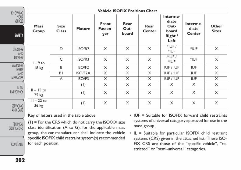
Vehicle ISOFIX Positions Chart
MassGroup
SizeClass
FixtureFront
Passen-ger
RearOut-board
RearCenter
Interme-diateOut-boardRight /
Left
Interme-diate
Center
OtherSites
I – 9 to18 kg
D ISO/R2 X X X*IUF /*IUF
*IUF X
C ISO/R3 X X X*IUF /*IUF
*IUF X
B ISO/F2 X X X IUF / IUF IUF XB1 ISO/F2X X X X IUF / IUF IUF XA ISO/F3 X X X IUF / IUF IUF X
(1) X X X X X XII – 15 to
25 kg(1) X X X X X X
III – 22 to36 kg
(1) X X X X X X
Key of letters used in the table above:
(1) = For the CRS which do not carry the ISO/XX sizeclass identification (A to G), for the applicable massgroup, the car manufacturer shall indicate the vehiclespecific ISOFIX child restraint system(s) recommendedfor each position.
• IUF = Suitable for ISOFIX forward child restraintssystems of universal category approved for use in themass group.
• IL = Suitable for particular ISOFIX child restraintsystems (CRS) given in the attached list. These ISO-FIX CRS are those of the “specific vehicle”, “re-stricted” or “semi-universal” catagories.
202
KNOWINGYOUR
VEHICLE
SAFETY
STARTINGAND
DRIVING
WARNINGLIGHTS
ANDMESSAGES
IN ANEMERGENCY
SERVICINGAND CARE
TECHNICALSPECIFICATIONS
CONTENTS

• X = ISOFIX position not suitable for ISOFIX childrestraint systems in this mass group and / or this sizeclass.
• * = Seats in front of child restraint seats may need tobe adjusted forward to install the child restraint seat.
• ** = No access to 3rd row seating positions ifCarrycot is installed in vehicle.
There are different sizes and types of restraints forchildren from newborn size to the child almost largeenough for an adult safety belt. Always check the childseat Owner's Manual to ensure you have the correct seatfor your child. Before buying any restraint system, makesure that it has a label certifying that it meets all appli-cable Safety Standards. You should also make sure thatyou can install it in the vehicle where you will use it.
Summary Of Recommendations For Restraining Children InVehicles
Child Size, Height,Weight or Age
RecommendedType ofChild Restraint
Infants and Toddlers
Children who are two years old oryounger and who have not reachedthe height or weight limits of their
child restraint
Either an Infant Carrier or a Convert-ible Child Restraint, facing rearward
in the rear seat of the vehicle
Small Children
Children who are at least two yearsold or who have out-grown theheight or weight limit of their
rear-facing child restraint
Forward-Facing Child Restraint with afive-point Harness, facing forward in
the rear seat of the vehicle
Larger Children
Children who have out-grown theirforward-facing child restraint, but aretoo small to properly fit the vehicle’s
seat belt
Belt Positioning Booster Seat and thevehicle seat belt, seated in the rear
seat of the vehicle
Children Too Large forChild Restraints
Children 12 years old or younger,who have out-grown the height orweight limit of their booster seat
Vehicle Seat Belt, seated in the rearseat of the vehicle
203
KNOWINGYOURVEHICLE
SAFETY
STARTINGANDDRIVING
WARNINGLIGHTSANDMESSAGES
IN ANEMERGENCY
SERVICINGAND CARE
TECHNICALSPECIFICATIONS
CONTENTS

Infants And Child RestraintsSafety experts recommend that children riderearward-facing in the vehicle until they are two yearsold or until they reach either the height or weight limitof their rear facing child safety seat. Two types of childrestraints can be used rearward-facing: infant carriersand convertible child seats.
The infant carrier is only used rearward-facing in thevehicle. It is recommended for children from birth untilthey reach the weight or height limit of the infantcarrier. Convertible child seats can be used eitherrearward-facing or forward-facing in the vehicle. Con-vertible child seats often have a higher weight limit inthe rearward-facing direction than infant carriers do, sothey can be used rearward-facing by children who haveoutgrown their infant carrier but are still less than atleast two years old. Children should remain rearward-facing until they reach the highest weight or heightallowed by their convertible child seat.
WARNING!• Never place a rear facing infant seat infront of an air bag.A deploying Passen-
ger Advanced Front Air Bag can cause death orserious injury to a child 12 years or younger,including a child in a rearward facing infant seat.• Only use a rearward-facing child restraint in avehicle with a rear seat.
Older Children And Child RestraintsChildren who are two years old or who have outgrowntheir rear-facing convertible child seat can rideforward-facing in the vehicle. Forward-facing childseats and convertible child seats used in the forward-facing direction are for children who are over two yearsold or who have outgrown the rear-facing weight orheight limit of their rear-facing convertible child seat.Children should remain in a forward-facing child seatwith a harness for as long as possible, up to the highestweight or height allowed by the child seat.
All children whose weight or height is above theforward-facing limit for the child seat should use abelt-positioning booster seat until the vehicle’s seat
204
KNOWINGYOUR
VEHICLE
SAFETY
STARTINGAND
DRIVING
WARNINGLIGHTS
ANDMESSAGES
IN ANEMERGENCY
SERVICINGAND CARE
TECHNICALSPECIFICATIONS
CONTENTS

belts fit properly. If the child cannot sit with knees bentover the vehicle’s seat cushion while the child’s back isagainst the seatback, they should use a belt-positioningbooster seat. The child and belt-positioning boosterseat are held in the vehicle by the seat belt.
WARNING!• Improper installation can lead to fail-ure of an infant or child restraint. It
could come loose in a collision.The child could bebadly injured or killed. Follow the child restraintmanufacturer’s directions exactly when install-ing an infant or child restraint.• When your child restraint is not in use, secureit in the vehicle with the seat belt or ISOFIXanchorages,or remove it from the vehicle.Do notleave it loose in the vehicle. In a sudden stop oraccident, it could strike the occupants or seat-backs and cause serious personal injury.
Integrated Child Booster Seat — forversions/markets, where providedThe Integrated Child Booster Seat is located in eachoutboard second-row passenger seat. The BoosterSeat is designed for children weighing between 22 and39 kg and between 119 cm and 145 cm tall.
To position a child into the Integrated Child BoosterSeat follow these steps:
1. Slide the second row seat to the full rear position touse the Integrated Child Booster Seat.
NOTE: The second row bench with Integrated ChildBooster Seat must remain in the full rear positionduring use.
2. Pull the release loop forward to release the latchand seat cushion. (fig. 140)
(fig. 140)Release Loop
205
KNOWINGYOURVEHICLE
SAFETY
STARTINGANDDRIVING
WARNINGLIGHTSANDMESSAGES
IN ANEMERGENCY
SERVICINGAND CARE
TECHNICALSPECIFICATIONS
CONTENTS

3. Lift the seat cushion up and push back to lock it inthe booster seat position. (fig. 141)
4. Place the child upright in the seat with their backfirmly against the seatback.
5. Grasp the latch plate and pull out the seat belt.
6. Slide the latch plate up the webbing as far as neces-sary to allow the seat belt to go around the child’slap.
NOTE: The lap portion of the seat belt should be lowon the hips and as snug as possible.
7. Once the seat belt is long enough to fit properly,insert the latch plate into the buckle until you heara “click.” (fig. 142)
8. To remove the slack from the lap belt, pull upwardon the shoulder portion of the seat belt.
9. To release the seat belt, push the red button on thebuckle.
(fig. 141)Booster Seat (fig. 142)
206
KNOWINGYOUR
VEHICLE
SAFETY
STARTINGAND
DRIVING
WARNINGLIGHTS
ANDMESSAGES
IN ANEMERGENCY
SERVICINGAND CARE
TECHNICALSPECIFICATIONS
CONTENTS

WARNING!Securely lock the seat cushion into posi-tion before using the seat. Otherwise,
the seat will not provide the proper stability forchild seats and/or passengers. An improperlylatched seat cushion could cause serious injury.
ChildrenToo Large For Booster SeatsChildren who are large enough to wear the shoulderbelt comfortably, and whose legs are long enough tobend over the front of the seat when their back isagainst the seatback, should use the seat belt in a rearseat. Use this simple 5-step test to decide whether thechild can use the vehicle’s seat belt alone:
1. Can the child sit all the way back against the back ofthe vehicle seat?
2. Do the child’s knees bend comfortably over thefront of the vehicle seat – while they are still sittingall the way back?
3. Does the shoulder belt cross the child’s shoulderbetween their neck and arm?
4. Is the lap part of the belt as low as possible, touchingthe child’s thighs and not their stomach?
5. Can the child stay seated like this for the whole trip?
If the answer to any of these questions was “no,” thenthe child still needs to use a booster seat in this vehicle.If the child is using the lap/shoulder belt, check belt fitperiodically. A child’s squirming or slouching can movethe belt out of position. If the shoulder belt contactsthe face or neck, move the child closer to the center ofthe vehicle. Never allow a child to put the shoulder beltunder an arm or behind their back.
207
KNOWINGYOURVEHICLE
SAFETY
STARTINGANDDRIVING
WARNINGLIGHTSANDMESSAGES
IN ANEMERGENCY
SERVICINGAND CARE
TECHNICALSPECIFICATIONS
CONTENTS

Recommendations For Attaching Child Restraints
RestraintType
CombinedWeight of theChild + Child
Restraint
Use any attachment method shown with an “X” Below
ISOFIX –Lower
Anchors OnlySeat Belt Only
ISOFIX –Lower
Anchors +TopTether Anchor
Seat Belt +TopTether Anchor
Rear-Facing ChildRestraint
Up to 29 kg X X
Rear-Facing ChildRestraint
More than 29 kg X
Forward-FacingChild Restraint
Up to 29 kg X X
Forward-FacingChild Restraint
More than 29 kg X
ISOFIX Restraint SystemYour vehicle is equipped with the child restraint an-chorage system called ISOFIX. The ISOFIX system hasthree vehicle anchor points for installing ISOFIX-equipped child seats. There are two lower anchorageslocated at the back of the seat cushion where it meetsthe seatback and one top tether anchorage located
behind the seating position. These anchorages are usedto install ISOFIX-equipped child seats without usingthe vehicle’s seat belts. Some seating positions mayhave a top tether anchorage but no lower anchorages.In these seating positions, the seat belt must be usedwith the top tether anchorage to install the childrestraint.
208
KNOWINGYOUR
VEHICLE
SAFETY
STARTINGAND
DRIVING
WARNINGLIGHTS
ANDMESSAGES
IN ANEMERGENCY
SERVICINGAND CARE
TECHNICALSPECIFICATIONS
CONTENTS

LocatingThe ISOFIX Anchorages
The lower anchorages are round bars that arefound at the rear of the seat cushion where itmeets the seatback. They are just visiblewhen you lean into the rear seat to install the
child restraint. You will easily feel them if you run yourfinger along the gap between the seatback and seatcushion. (fig. 143)
LocatingThe ISOFIX Anchorages(Second Row Seating)
In addition, there are tether strap anchorslocated behind each rear seatback, near tothe floor. (fig. 144)
ISOFIX child restraint systems will be equipped with arigid bar on each side. Each will have a connector toattach to the lower anchorage and a way to tighten theconnection to the anchorage. Forward-facing child re-straints and some rear-facing infant restraints will alsobe equipped with a tether strap. The tether strap willhave a hook at the end to attach to the top tetheranchorage and a way to tighten the strap after it isattached to the anchorage.
(fig. 143)ISOFIX Anchorages
(fig. 144)Tether Strap Anchors
209
KNOWINGYOURVEHICLE
SAFETY
STARTINGANDDRIVING
WARNINGLIGHTSANDMESSAGES
IN ANEMERGENCY
SERVICINGAND CARE
TECHNICALSPECIFICATIONS
CONTENTS

Center Seat ISOFIXThis vehicle has 5 lower ISOFIX anchorages in the rearseat. Anchorages A and B are used for the right out-board position behind the front passenger (1). Anchor-ages D and E are used for the left outboard positionbehind the driver (3). Anchorages B and C are used forthe center seating position (2). Do not install an ISO-FIX child restraint using anchorages C and D. This isnot a ISOFIX position in your vehicle.
You can install up to two child seats using the ISOFIXsystem at the same time. If you are installing three childrestraints, you must use the seatbelt to install thecenter child restraint. You can use either the ISOFIXanchors for positions (1) and (3) or the vehicle’s seatbelt for installing the child seats in the outboard posi-tions. (fig. 145)
Options for installing two child seats using the ISOFIXanchorages in this vehicle:
1. Right and left outboard seating positions (1 and 3):Install the child seats in the right and left outboardseating positions using lower anchorages A and B,and D and E. Do not use the center seat anchorage,C. If the child seats do not block the center seat beltwebbing and buckle, the center seat belt can beused to restraint an occupant or child restraint inthe center seating position.
2. Left outboard and center seating positions (3 and 2):Install the first child seat in the left outboard seatingposition using lower anchorages D and E. Install thesecond child seat using the center anchorages, B andC. Do not use the outer anchorage closest to theopposite door, A. Do not use the remaining rightoutboard seating position (1) for any occupant. Thecenter child restraint will block the seat belt bucklefor this position.
(fig. 145)
210
KNOWINGYOUR
VEHICLE
SAFETY
STARTINGAND
DRIVING
WARNINGLIGHTS
ANDMESSAGES
IN ANEMERGENCY
SERVICINGAND CARE
TECHNICALSPECIFICATIONS
CONTENTS

WARNING!• Use anchorages B and C to install aISOFIX child restraint in the center seat-
ing position (2). Do not install a ISOFIX childrestraint using anchorages C and D.This is not anISOFIX position in your vehicle.• A child restraint installed in the center position(2) will block the seat belt buckle for the emptyright outboard seating position (1). Do not usethis seat for another occupant.• Never use the same lower anchorage to attachmore than one child restraint.• If you are installing three child restraints nextto each other, you must use the seat belt and thecenter tether anchor for the center position.Youcan then use either the ISOFIX anchors or thevehicle’s seat belt for installing the child seats inthe outboard positions.Please refer to“Installingthe ISOFIX Child Restraint System” for typicalinstallation instructions.
Always follow the directions of the child restraintmanufacturer when installing your child restraint. Notall child restraint systems will be installed as describedhere.
To Install An ISOFIX Child Restraint:
1. If the selected seating position has a SwitchableAutomatic Locking Retractor (ALR) seat belt, stowthe seat belt, following the instructions below. Seethe section “Installing Child Restraints Using theVehicle Seat Belt” to check what type of seat belteach seating position has.
2. Loosen the adjusters on the lower connectors andon the tether strap of the child seat so that you canmore easily attach the connectors to the vehicleanchorages.
3. Place the child seat between the lower anchoragesfor that seating position. For some second rowseats, you may need to recline the seat and / or raisethe head restraint to get a better fit. If the rear seatcan be moved forward and rearward in the vehicle,you may wish to move it to its rear-most position tomake room for the child seat. You may also movethe front seat forward to allow more room for thecar seat.
4. Attach the connectors of the child restraint to thelower anchorages in the selected seating position.
211
KNOWINGYOURVEHICLE
SAFETY
STARTINGANDDRIVING
WARNINGLIGHTSANDMESSAGES
IN ANEMERGENCY
SERVICINGAND CARE
TECHNICALSPECIFICATIONS
CONTENTS

5. If the child restraint has a tether strap, connect it tothe top tether anchorage. See the section “InstallingChild Restraints Using the Top Tether Anchorage”for directions to attach a tether anchor.
6. Tighten all of the straps as you push the childrestraint rearward and downward into the seat.Remove slack in the straps according to the childrestraint manufacturer’s instructions.
7. Test that the child restraint is installed tightly bypulling back and forth on the child seat at the beltpath. It should not move more than 25 mm in anydirection.
HowTo Stow An Unused ALR SeatbeltWhen using the ISOFIX attaching system to install achild restraint, stow all ALR seat belts that are notbeing used by other occupants or being used to securechild restraints. An unused belt could injure a child ifthey play with it and accidentally lock the seatbeltretractor. Before installing a child restraint using theISOFIX system, buckle the seat belt behind the childrestraint and out of the child’s reach. If the buckled seatbelt interferes with the child restraint installation, in-stead of buckling it behind the child restraint, route theseat belt through the child restraint belt path and thenbuckle it. Do not lock the seatbelt. Remind all childrenin the vehicle that the seat belts are not toys and thatthey should not play with them.
WARNING!• Improper installation of a child re-straint to the ISOFIX anchorages can
lead to failure of an infant or child restraint.Thechild could be badly injured or killed. Follow themanufacturer's directions exactly when installingan infant or child restraint.• Child restraint anchorages are designed towithstand only those loads imposed by correctly-fitted child restraints. Under no circumstancesare they to be used for adult seat belts,harnesses,or for attaching other items or equipment to thevehicle.
Installing Child Restraints UsingTheVehicleSeat BeltThe seat belts in the passenger seating positions areequipped with either a Switchable Automatic LockingRetractor (ALR) or a cinching latch plate or both. Bothtypes of seat belts are designed to keep the lap portionof the seat belt tight around the child restraint so thatit is not necessary to use a locking clip. The ALRretractor can be “switched” into a locked mode bypulling all of the webbing out of the retractor and thenletting the webbing retract back into the retractor. If itis locked, the ALR will make a clicking noise while thewebbing is pulled back into the retractor. For additionalinformation on ALR, refer to the “Automatic Locking
212
KNOWINGYOUR
VEHICLE
SAFETY
STARTINGAND
DRIVING
WARNINGLIGHTS
ANDMESSAGES
IN ANEMERGENCY
SERVICINGAND CARE
TECHNICALSPECIFICATIONS
CONTENTS

Mode” description under “Occupant Restraints.” Thecinching latch plate is designed to hold the lap portionof the seatbelt tight when webbing is pulled tight andstraight through a child restraint’s belt path.
Installing A Child Restraint With A SwitchableAutomatic Locking Retractor (ALR)
1. Place the child seat in the center of the seatingposition. For some second row seats, you may needto recline the seat and/or raise the head restraint toget a better fit. If the rear seat can be movedforward and rearward in the vehicle, you may wishto move it to its rear-most position to make roomfor the child seat. You may also move the front seatforward to allow more room for the car seat.
2. Pull enough of the seat belt webbing from theretractor to pass it through the belt path of the childrestraint. Do not twist the belt webbing in the beltpath.
3. Slide the latch plate into the buckle until you hear a“click.”
4. Pull on the webbing to make the lap portion tightagainst the child seat.
5. To lock the seat belt, pull down on the shoulder partof the belt until you have pulled all the seat beltwebbing out of the retractor. Then, allow the web-bing to retract back into the retractor. As the
webbing retracts, you will hear a clicking sound. Thismeans the seat belt is now in the Automatic Lockingmode.
6. Try to pull the webbing out of the retractor. If it islocked, you should not be able to pull out anywebbing. If the retractor is not locked, repeatstep 5.
7. Finally, pull up on any excess webbing to tighten thelap portion around the child restraint while youpush the child restraint rearward and downwardinto the vehicle seat.
8. If the child restraint has a top tether strap and theseating position has a top tether anchorage, con-nect the tether strap to the anchorage and tightenthe tether strap. See the section “Installing ChildRestraints Using the Top Tether Anchorage” fordirections to attach a tether anchor.
9. Test that the child restraint is installed tightly bypulling back and forth on the child seat at the beltpath. It should not move more than 25 mm in anydirection.
Any seat belt system will loosen with time, so checkthe belt occasionally, and pull it tight if necessary.
213
KNOWINGYOURVEHICLE
SAFETY
STARTINGANDDRIVING
WARNINGLIGHTSANDMESSAGES
IN ANEMERGENCY
SERVICINGAND CARE
TECHNICALSPECIFICATIONS
CONTENTS

Installing A Child Restraint With A CinchingLatch Plate (CINCH) — for versions/markets,where provided
1. Place the child seat in the center of the seatingposition. For some second row seats, you may needto recline the seat and / or raise the head restraintto get a better fit. If the rear seat can be movedforward and rearward in the vehicle, you may wishto move it to its rear-most position to make roomfor the child seat. You may also move the front seatforward to allow more room for the car seat.
2. Next, pull enough of the seat belt webbing from theretractor to pass it through the belt path of the childrestraint. Do not twist the belt webbing in the beltpath.
3. Slide the latch plate into the buckle until you hear a“click.”
4. Finally, pull up on any excess webbing to tighten thelap portion around the child restraint while youpush the child restraint rearward and downwardinto the vehicle seat.
5. If the child restraint has a top tether strap and theseating position has a top tether anchorage, con-nect the tether strap to the anchorage and tightenthe tether strap. Refer to “Installing Child Restraints
Using The Top Tether Anchorage” for directions toattach a tether anchor.
6. Test that the child restraint is installed tightly bypulling back and forth on the child seat at the beltpath. It should not move more than 25 mm in anydirection.
Any seat belt system will loosen with time, so checkthe belt occasionally, and pull it tight if necessary.
If the buckle or the cinching latch plate is too close tothe belt path opening of the child restraint, you mayhave trouble tightening the seat belt. If this happens,disconnect the latch plate from the buckle and twistthe short buckle-end belt up to three full turns toshorten it. Insert the latch plate into the buckle withthe release button facing out, away from the childrestraint. Repeat steps 4 to 6, above, to complete theinstallation of the child restraint.
If the belt still cannot be tightened after you shortenthe buckle, disconnect the latch plate from the buckle,turn the buckle around one half turn, and insert thelatch plate into the buckle again. If you still cannot makethe child restraint installation tight, try a differentseating position.
214
KNOWINGYOUR
VEHICLE
SAFETY
STARTINGAND
DRIVING
WARNINGLIGHTS
ANDMESSAGES
IN ANEMERGENCY
SERVICINGAND CARE
TECHNICALSPECIFICATIONS
CONTENTS
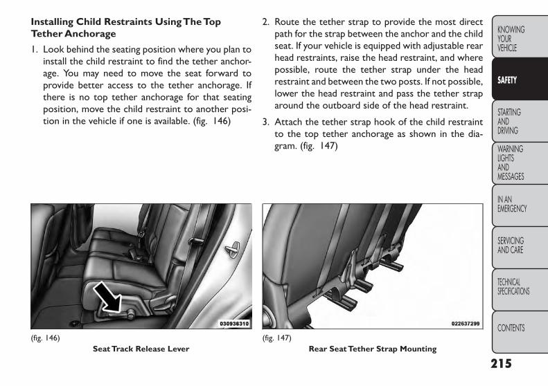
Installing Child Restraints UsingTheTopTether Anchorage
1. Look behind the seating position where you plan toinstall the child restraint to find the tether anchor-age. You may need to move the seat forward toprovide better access to the tether anchorage. Ifthere is no top tether anchorage for that seatingposition, move the child restraint to another posi-tion in the vehicle if one is available. (fig. 146)
2. Route the tether strap to provide the most directpath for the strap between the anchor and the childseat. If your vehicle is equipped with adjustable rearhead restraints, raise the head restraint, and wherepossible, route the tether strap under the headrestraint and between the two posts. If not possible,lower the head restraint and pass the tether straparound the outboard side of the head restraint.
3. Attach the tether strap hook of the child restraintto the top tether anchorage as shown in the dia-gram. (fig. 147)
(fig. 146)SeatTrack Release Lever
(fig. 147)Rear SeatTether Strap Mounting
215
KNOWINGYOURVEHICLE
SAFETY
STARTINGANDDRIVING
WARNINGLIGHTSANDMESSAGES
IN ANEMERGENCY
SERVICINGAND CARE
TECHNICALSPECIFICATIONS
CONTENTS
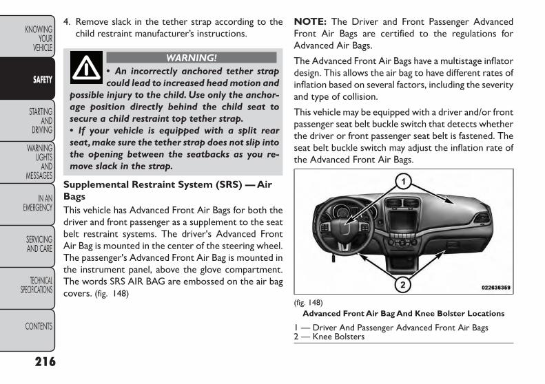
4. Remove slack in the tether strap according to thechild restraint manufacturer’s instructions.
WARNING!• An incorrectly anchored tether strapcould lead to increased head motion and
possible injury to the child. Use only the anchor-age position directly behind the child seat tosecure a child restraint top tether strap.• If your vehicle is equipped with a split rearseat,make sure the tether strap does not slip intothe opening between the seatbacks as you re-move slack in the strap.
Supplemental Restraint System (SRS) — AirBagsThis vehicle has Advanced Front Air Bags for both thedriver and front passenger as a supplement to the seatbelt restraint systems. The driver's Advanced FrontAir Bag is mounted in the center of the steering wheel.The passenger's Advanced Front Air Bag is mounted inthe instrument panel, above the glove compartment.The words SRS AIR BAG are embossed on the air bagcovers. (fig. 148)
NOTE: The Driver and Front Passenger AdvancedFront Air Bags are certified to the regulations forAdvanced Air Bags.
The Advanced Front Air Bags have a multistage inflatordesign. This allows the air bag to have different rates ofinflation based on several factors, including the severityand type of collision.
This vehicle may be equipped with a driver and/or frontpassenger seat belt buckle switch that detects whetherthe driver or front passenger seat belt is fastened. Theseat belt buckle switch may adjust the inflation rate ofthe Advanced Front Air Bags.
(fig. 148)Advanced Front Air Bag And Knee Bolster Locations
1 — Driver And Passenger Advanced Front Air Bags2 — Knee Bolsters
216
KNOWINGYOUR
VEHICLE
SAFETY
STARTINGAND
DRIVING
WARNINGLIGHTS
ANDMESSAGES
IN ANEMERGENCY
SERVICINGAND CARE
TECHNICALSPECIFICATIONS
CONTENTS

This vehicle is equipped with Supplemental Side Air BagInflatable Curtains (SABIC) to protect the driver, front,and rear passengers sitting next to a window. TheSABIC air bags are located above the side windows andtheir covers are also labeled: SRS AIRBAG.
This vehicle is equipped with Supplemental Seat-Mounted Side Air Bags (SAB). The Supplemental Seat-Mounted Side Air Bags are marked with an air bag labelsewn into the outboard side of the front seats.
NOTE:
• Air Bag covers may not be obvious in the interiortrim, but they will open during air bag deployment.
• After any accident, the vehicle should be taken to anauthorized dealer immediately.
Air Bag System ComponentsYour vehicle may be equipped with the following air bagsystem components:
• Occupant Restraint Controller (ORC)
• Air Bag Warning Light
• Steering Wheel and Column
• Instrument Panel
• Knee Impact Bolsters
• Driver Advanced Front Air Bag
• Passenger Advanced Front Air Bag
• Supplemental Seat-Mounted Side Air Bags (SAB)
• Supplemental Side Air Bag Inflatable Curtains(SABIC)
• Front and Side Impact Sensors
• Front Seat Belt Pretensioners
• Seat Belt Buckle Switch
Advanced Front Air Bag FeaturesThe Advanced Front Air Bag system has multistagedriver and front passenger air bags. This system pro-vides output appropriate to the severity and type ofcollision as determined by the Occupant RestraintController (ORC), which may receive informationfrom the front impact sensors.
217
KNOWINGYOURVEHICLE
SAFETY
STARTINGANDDRIVING
WARNINGLIGHTSANDMESSAGES
IN ANEMERGENCY
SERVICINGAND CARE
TECHNICALSPECIFICATIONS
CONTENTS

The first stage inflator is triggered immediately duringan impact that requires air bag deployment. This lowoutput is used in less severe collisions. A higher energyoutput is used for more severe collisions.
WARNING!• No objects should be placed over ornear the air bag on the instrument
panel, because any such objects could causeharm if the vehicle is in a collision severe enoughto cause the air bag to inflate.• Do not put anything on or around the air bagcovers or attempt to open them manually. Youmay damage the air bags and you could beinjured because the air bags may no longer befunctional.The protective covers for the air bagcushions are designed to open only when the airbags are inflating.• Do not drill, cut or tamper with the knee bol-ster in any way.• Do not mount any accessories to the kneebolster such as alarm lights, stereos, citizen bandradios, etc.
Supplemental Seat-Mounted Side Air Bags(SAB)SAB may provide enhanced protection to help protectan occupant during a side impact. The SAB is markedwith an air bag label sewn into the outboard side of thefront seats. (fig. 149)
When the air bag deploys, it opens the seam betweenthe front and side of the seat's trim cover. Each air bagdeploys independently; a left side impact deploys theleft air bag only and a right-side impact deploys theright air bag only.
(fig. 149)Seat Mounted Side Air Bag Label
218
KNOWINGYOUR
VEHICLE
SAFETY
STARTINGAND
DRIVING
WARNINGLIGHTS
ANDMESSAGES
IN ANEMERGENCY
SERVICINGAND CARE
TECHNICALSPECIFICATIONS
CONTENTS
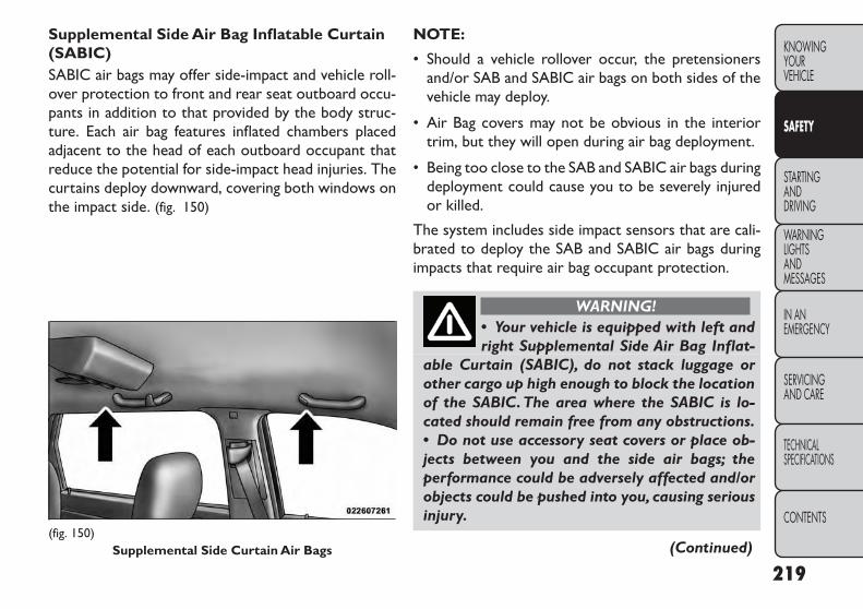
Supplemental Side Air Bag Inflatable Curtain(SABIC)SABIC air bags may offer side-impact and vehicle roll-over protection to front and rear seat outboard occu-pants in addition to that provided by the body struc-ture. Each air bag features inflated chambers placedadjacent to the head of each outboard occupant thatreduce the potential for side-impact head injuries. Thecurtains deploy downward, covering both windows onthe impact side. (fig. 150)
NOTE:
• Should a vehicle rollover occur, the pretensionersand/or SAB and SABIC air bags on both sides of thevehicle may deploy.
• Air Bag covers may not be obvious in the interiortrim, but they will open during air bag deployment.
• Being too close to the SAB and SABIC air bags duringdeployment could cause you to be severely injuredor killed.
The system includes side impact sensors that are cali-brated to deploy the SAB and SABIC air bags duringimpacts that require air bag occupant protection.
WARNING!• Your vehicle is equipped with left andright Supplemental Side Air Bag Inflat-
able Curtain (SABIC), do not stack luggage orother cargo up high enough to block the locationof the SABIC. The area where the SABIC is lo-cated should remain free from any obstructions.• Do not use accessory seat covers or place ob-jects between you and the side air bags; theperformance could be adversely affected and/orobjects could be pushed into you, causing seriousinjury.
(Continued)(fig. 150)
Supplemental Side Curtain Air Bags
219
KNOWINGYOURVEHICLE
SAFETY
STARTINGANDDRIVING
WARNINGLIGHTSANDMESSAGES
IN ANEMERGENCY
SERVICINGAND CARE
TECHNICALSPECIFICATIONS
CONTENTS

(Continued)• Your vehicle is equipped with SABIC air bags,do not have any accessory items installed whichwill alter the roof, including adding a sunroof toyour vehicle. Do not add roof racks that requirepermanent attachments (bolts or screws) for in-stallation on the vehicle roof.Do not drill into theroof of the vehicle for any reason.
SAB and SABIC air bags are a supplement to the seatbelt restraint system. Occupants, including childrenwho are up against or very close to SAB or SABIC airbags can be seriously injured or killed. Occupants,especially children, should not lean on or sleep againstthe door, side windows, or area where the SAB orSABIC air bags inflate, even if they are in an infant orchild restraint.
Always sit upright as possible with your back againstthe seat back, use the seat belts properly, and use theappropriate sized child restraint, infant restraint orbooster seat recommended for the size and weight ofthe child.
Knee Impact BolstersThe Knee Impact Bolsters help protect the knees ofthe driver and front passenger, and position the frontoccupants for the best interaction with the AdvancedFront Air Bags.
Along with seat belts and pretensioners, AdvancedFront Air Bags and the Supplemental Driver Side KneeAir Bag work with the knee impact bolsters to provideimproved protection for the driver and front passenger.
Air Bag Deployment Sensors And Controls
Occupant Restraint Controller (ORC)The ORC is part of a regulated safety system requiredfor this vehicle.
The ORC determines if deployment of the front and/orside air bags in a frontal or side collision is required.Based on the impact sensor's signals, a central electronicORC deploys the Advanced Front Air Bags, SABIC airbags, Supplemental Seat-Mounted Side Air Bags, andfront seat belt pretensioners, as required, depending onseveral factors, including the severity and type of impact.
The Advanced Front Air Bags are designed to provideadditional protection by supplementing the seat beltsin certain frontal collisions depending on several fac-tors, including the severity and type of collision. Ad-vanced Front Air Bags are not expected to reduce therisk of injury in rear, side, or rollover collisions.
The Advanced Front Air Bags will not deploy in allfrontal collisions, including some that may producesubstantial vehicle damage — for example, some polecollisions, truck underrides, and angle offset collisions.On the other hand, depending on the type and location
220
KNOWINGYOUR
VEHICLE
SAFETY
STARTINGAND
DRIVING
WARNINGLIGHTS
ANDMESSAGES
IN ANEMERGENCY
SERVICINGAND CARE
TECHNICALSPECIFICATIONS
CONTENTS

of impact, Advanced Front Air Bags may deploy incrashes with little vehicle front-end damage but thatproduce a severe initial deceleration.
The side air bags will not deploy in all side collisions.Side air bag deployment will depend on the severity andtype of collision.
Because air bag sensors measure vehicle decelerationover time, vehicle speed and damage by themselves arenot good indicators of whether or not an air bag shouldhave deployed.
Seat belts are necessary for your protection in allcollisions, and also are needed to help keep you inposition, away from an inflating air bag.
The ORC monitors the readiness of the electronicparts of the air bag system whenever the ignition is inthe ON/RUN position. If the ignition is in the OFFposition, or in the ACC position, the air bag system isnot on and the air bags will not inflate.
The ORC contains a backup power supply system thatmay deploy the air bags even if the battery loses poweror it becomes disconnected prior to deployment.
Also, the ORC turns on the Air Bag WarningLight in the instrument panel for approxi-mately four to eight seconds for a self-check
when the ignition is first turned on. After the self-check, the Air Bag Warning Light will turn off. If the
ORC detects a malfunction in any part of the system, itturns on the Air Bag Warning Light, either momentarilyor continuously. A single chime will sound if the lightcomes on again after initial startup.
It also includes diagnostics that will illuminate theinstrument cluster Air Bag Warning Light if a malfunc-tion is noted that could affect the air bag system. Thediagnostics also record the nature of the malfunction.
WARNING!Ignoring the Air Bag Warning Light inyour instrument panel could mean you
won't have the air bags to protect you in acollision. If the light does not come on as a bulbcheck when the ignition is first turned on, stayson after you start the vehicle, or if it comes on asyou drive, have an authorized dealer service theair bag system immediately.
Driver And Passenger Advanced Front Air BagInflator UnitsThe Driver and Passenger Advanced Front Air Bag Infla-tor Units are located in the center of the steering wheeland on the right side of the instrument panel. When theORC detects a collision requiring the Advanced FrontAir Bags, it signals the inflator units. A large quantity ofnon-toxic gas is generated to inflate the Advanced Front
221
KNOWINGYOURVEHICLE
SAFETY
STARTINGANDDRIVING
WARNINGLIGHTSANDMESSAGES
IN ANEMERGENCY
SERVICINGAND CARE
TECHNICALSPECIFICATIONS
CONTENTS

Air Bags. Different air bag inflation rates are possible,based on several factors, including the collision type andseverity. The steering wheel hub trim cover and theupper right side of the instrument panel separate andfold out of the way as the air bags inflate to their full size.The air bags fully inflate in about 50 to 70 milliseconds.This is about half of the time it takes to blink your eyes.The air bags then quickly deflate while helping to restrainthe driver and front passenger.
The Advanced Front Air Bag gas is vented through thevent holes in the sides of the air bag. In this way, the airbags do not interfere with your control of the vehicle.
Supplemental Seat-Mounted Side Air Bag(SAB) Inflator UnitsThe Supplemental Seat-Mounted Side Air Bags (SAB)are designed to activate only in certain side collisions.
The ORC determines if a side collision requires theside air bags to inflate, based on the severity and type ofcollision.
Based on the severity and type of collision, the side airbag inflator on the crash side of the vehicle may betriggered, releasing a large quantity of non-toxic gas.The inflating SAB exits through the seat seam into thespace between the occupant and the door. The SABfully inflates in about 10 milliseconds. The side air bagmoves at a very high speed and with such a high forcethat it could injure you if you are not seated properly,
or if items are positioned in the area where the side airbag inflates. This especially applies to children.
Supplemental Side Air Bag Inflatable Curtain(SABIC) Inflator UnitsDuring collisions where the impact is confined to aparticular area of the side of the vehicle, the ORC maydeploy the SABIC air bags, depending on the severity andtype of collision. In these events, the ORC will deploythe SABIC only on the impact side of the vehicle.
A quantity of non-toxic gas is generated to inflate theside curtain air bag. The inflating side curtain air bagpushes the outside edge of the headliner out of the wayand covers the window. The air bag inflates in about 30milliseconds (about one-quarter of the time that it takesto blink your eyes) with enough force to injure you if youare not belted and seated properly, or if items arepositioned in the area where the side curtain air baginflates. This especially applies to children. The sidecurtain air bag is only about 9 cm thick when it is inflated.
Because air bag sensors estimate deceleration overtime, vehicle speed and damage are not good indicatorsof whether or not an air bag should have deployed.
NOTE: In a rollover the pretensioners and/or SAB andSABIC air bags may deploy on both sides of the vehicle.
222
KNOWINGYOUR
VEHICLE
SAFETY
STARTINGAND
DRIVING
WARNINGLIGHTS
ANDMESSAGES
IN ANEMERGENCY
SERVICINGAND CARE
TECHNICALSPECIFICATIONS
CONTENTS

Front And Side Impact SensorsIn front and side impacts, impact sensors can aid the ORCin determining appropriate response to impact events.
Enhanced Accident Response SystemIn the event of an impact causing air bag deployment, ifthe communication network remains intact, and thepower remains intact, depending on the nature of theevent the ORC will determine whether to have theEnhanced Accident Response System perform the fol-lowing functions:
• Cut off fuel to the engine.
• Flash hazard lights as long as the battery has poweror until the ignition is cycled off.
• Turn on the interior lights, which remain on as longas the battery has power or until the ignition key isremoved.
• Unlock the doors automatically.
In order to reset the Enhanced Accident ResponseSystem functions after an event, the ignition switchmust be changed from IGN ON to IGN OFF.
If A Deployment OccursThe Advanced Front Air Bags are designed to deflateimmediately after deployment.
NOTE: Front and/or side air bags will not deploy in allcollisions. This does not mean something is wrong withthe air bag system.
If you do have a collision which deploys the air bags, anyor all of the following may occur:
• The nylon air bag material may sometimes causeabrasions and/or skin reddening to the driver andfront passenger as the air bags deploy and unfold.The abrasions are similar to friction rope burns orthose you might get sliding along a carpet or gymna-sium floor. They are not caused by contact withchemicals. They are not permanent and normallyheal quickly. However, if you haven't healed signifi-cantly within a few days, or if you have any blistering,see your doctor immediately.
• As the air bags deflate, you may see some smoke-likeparticles. The particles are a normal by-product ofthe process that generates the non-toxic gas used forair bag inflation. These airborne particles may irritatethe skin, eyes, nose, or throat. If you have skin or eyeirritation, rinse the area with cool water. For nose orthroat irritation, move to fresh air. If the irritationcontinues, see your doctor. If these particles settleon your clothing, follow the garment manufacturer'sinstructions for cleaning.
223
KNOWINGYOURVEHICLE
SAFETY
STARTINGANDDRIVING
WARNINGLIGHTSANDMESSAGES
IN ANEMERGENCY
SERVICINGAND CARE
TECHNICALSPECIFICATIONS
CONTENTS
Do not drive your vehicle after the air bags havedeployed. If you are involved in another collision, theair bags will not be in place to protect you.
WARNING!Deployed air bags and seat belt preten-sioners cannot protect you in another
collision. Have the air bags, seat belt pretension-ers, and the front seat belt retractor assembliesreplaced by an authorized dealer immediately.Also, have the Occupant Restraint Controller(ORC) system serviced as well.
Air Bag Warning Light
You will want to have the air bags ready toinflate for your protection in a collision. TheAir Bag Warning Light monitors the internalcircuits and interconnecting wiring associated
with air bag system electrical components. While theair bag system is designed to be maintenance free. If anyof the following occurs, have an authorized dealerservice the air bag system immediately.
• The Air Bag Warning Light does not come on duringthe four to eight seconds when the ignition is firstcycled to the ON/RUN.
• The Air Bag Warning Light remains on after the fourto eight-second interval.
• The Air Bag Warning Light comes on intermittentlyor remains on while driving.
NOTE: If the speedometer, tachometer, or any enginerelated gauges are not working, the Occupant Re-straint Controller (ORC) may also be disabled. The airbags may not be ready to inflate for your protection.Promptly check the fuse block for blown fuses. Refer to“Fuses” in “In An Emergency” for the proper air bagfuses. See your authorized dealer if the fuse is good.
EVENT DATA RECORDER (EDR)This vehicle is equipped with an event data recorder(EDR). The main purpose of an EDR is to record, incertain crash or near crash-like situations, such as anair bag deployment or hitting a road obstacle, data thatwill assist in understanding how a vehicle’s systemsperformed. The EDR is designed to record data relatedto vehicle dynamics and safety systems for a shortperiod of time, typically 30 seconds or less. The EDR inthis vehicle is designed to record such data as:
• How various systems in your vehicle were operating;
• Whether or not the driver and passenger safety beltswere buckled/fastened;
224
KNOWINGYOUR
VEHICLE
SAFETY
STARTINGAND
DRIVING
WARNINGLIGHTS
ANDMESSAGES
IN ANEMERGENCY
SERVICINGAND CARE
TECHNICALSPECIFICATIONS
CONTENTS

• How far (if at all) the driver was depressing theaccelerator and/or brake pedal; and,
• How fast the vehicle was traveling.
These data can help provide a better understanding ofthe circumstances in which crashes and injuries occur.
NOTE: EDR data are recorded by your vehicle only ifa non-trivial crash situation occurs; no data are re-corded by the EDR under normal driving conditionsand no personal data (e.g., name, gender, age, and crashlocation) are recorded. However, other parties, such aslaw enforcement, could combine the EDR data withthe type of personally identifying data routinely ac-quired during a crash investigation.
To read data recorded by an EDR, special equipment isrequired, and access to the vehicle or the EDR isneeded. In addition to the vehicle manufacturer, otherparties, such as law enforcement, that have the specialequipment, can read the information if they have accessto the vehicle or the EDR.
Transporting PetsAir Bags deploying in the front seat could harm yourpet. An unrestrained pet will be thrown about andpossibly injured, or injure a passenger during panicbraking or in a collision.
Pets should be restrained in the rear seat in pet har-nesses or pet carriers that are secured by seat belts.
SAFETY TIPSTransporting PassengersNEVER TRANSPORT PASSENGERS IN THE CARGOAREA.
WARNING!• Do not leave children or animals insideparked vehicles in hot weather. Interior
heat build-up may cause serious injury or death.• It is extremely dangerous to ride in a cargoarea, inside or outside of a vehicle. In a collision,people riding in these areas are more likely to beseriously injured or killed.• Do not allow people to ride in any area of yourvehicle that is not equipped with seats and seatbelts.• Be sure everyone in your vehicle is in a seat andusing a seat belt properly.• On seven passenger models, do not drive thevehicle with the second row passenger seat in theeasy entry/exit position (seat cushion flipped up-ward and seat moved forward), as this position isonly intended for entering and exiting the thirdrow seats. Failure to follow this warning mayresult in personal injury.
(Continued)
225
KNOWINGYOURVEHICLE
SAFETY
STARTINGANDDRIVING
WARNINGLIGHTSANDMESSAGES
IN ANEMERGENCY
SERVICINGAND CARE
TECHNICALSPECIFICATIONS
CONTENTS

(Continued)• On seven passenger models, do not allow apassenger to sit in a third row seat with thesecond row seatback(s) folded flat. In a collision,the passenger could slide underneath the seatbelt and be seriously or even fatally injured.
Exhaust Gas
WARNING!Exhaust gases can injure or kill. Theycontain carbon monoxide (CO), which is
colorless and odorless.Breathing it can make youunconscious and can eventually poison you. Toavoid breathing (CO), follow these safety tips:• Do not run the engine in a closed garage or inconfined areas any longer than needed to moveyour vehicle in or out of the area.• If you are required to drive with the trunk/liftgate/rear doors open, make sure that all win-dows are closed and the climate controlBLOWER switch is set at high speed.DO NOT usethe recirculation mode.• If it is necessary to sit in a parked vehicle withthe engine running,adjust your heating or coolingcontrols to force outside air into the vehicle. Setthe blower at high speed.
The best protection against carbon monoxide entryinto the vehicle body is a properly maintained engineexhaust system.
Whenever a change is noticed in the sound of theexhaust system, when exhaust fumes can be detectedinside the vehicle, or when the underside or rear of thevehicle is damaged, have a competent mechanic inspectthe complete exhaust system and adjacent body areasfor broken, damaged, deteriorated, or mispositionedparts. Open seams or loose connections could permitexhaust fumes to seep into the passenger compart-ment. In addition, inspect the exhaust system each timethe vehicle is raised for lubrication or oil change.Replace as required.
Safety ChecksYou Should Make InsideTheVehicle
Seat BeltsInspect the seat belt system periodically, checking forcuts, frays, and loose parts. Damaged parts must bereplaced immediately. Do not disassemble or modify thesystem.
Front seat belt assemblies must be replaced after acollision. Rear seat belt assemblies must be replacedafter a collision if they have been damaged (i.e., bentretractor, torn webbing, etc.). If there is any questionregarding belt or retractor condition, replace the seatbelt.
226
KNOWINGYOUR
VEHICLE
SAFETY
STARTINGAND
DRIVING
WARNINGLIGHTS
ANDMESSAGES
IN ANEMERGENCY
SERVICINGAND CARE
TECHNICALSPECIFICATIONS
CONTENTS

Air Bag Warning Light
The light should turn on and remain on forfour to six seconds as a bulb check when theignition switch is first turned ON. If the lightis not lit during starting, or if the light stays
on, flickers, or turns on while driving, have the systemchecked by an authorized dealer.
DefrosterCheck operation by selecting the defrost mode andplace the blower control on high speed. You should beable to feel the air directed against the windshield. Seeyour authorized dealer for service if your defroster isinoperable.
Floor Mat Safety InformationAlways use floor mats designed to fit the footwell ofyour vehicle. Use only floor mats that leave the pedalarea unobstructed and that are firmly secured so thatthey cannot slip out of position and interfere with thepedals or impair safe operation of your vehicle in otherways.
WARNING!Pedals that cannot move freely cancause loss of vehicle control and increase
the risk of serious personal injury.• Always make sure that floor mats are properlyattached to the floor mat fasteners.• Never place or install floor mats or other floorcoverings in the vehicle that cannot be properlysecured to prevent them from moving and inter-fering with the pedals or the ability to control thevehicle.• Never put floor mats or other floor coveringson top of already installed floor mats.Additionalfloor mats and other coverings will reduce thesize of the pedal area and interfere with thepedals.• Check mounting of mats on a regular basis.Always properly reinstall and secure floor matsthat have been removed for cleaning.• Always make sure that objects cannot fall intothe driver footwell while the vehicle is moving.Objects can become trapped under the brakepedal and accelerator pedal causing a loss ofvehicle control.• If required, mounting posts must be properlyinstalled, if not equipped from the factory.
(Continued)
227
KNOWINGYOURVEHICLE
SAFETY
STARTINGANDDRIVING
WARNINGLIGHTSANDMESSAGES
IN ANEMERGENCY
SERVICINGAND CARE
TECHNICALSPECIFICATIONS
CONTENTS

(Continued)Failure to properly follow floor mat installationor mounting can cause interference with thebrake pedal and accelerator pedal operationcausing loss of control of the vehicle.
Periodic Safety ChecksYou Should MakeOutsideTheVehicle
TiresExamine tires for excessive tread wear and unevenwear patterns. Check for stones, nails, glass, or otherobjects lodged in the tread or sidewall. Inspect thetread for cuts and cracks. Inspect sidewalls for cuts,cracks and bulges. Check the wheel nuts for tightness.Check the tires (including spare) for proper cold infla-tion pressure.
LightsHave someone observe the operation of brake lightsand exterior lights while you work the controls. Checkturn signal and high beam indicator lights on the instru-ment panel.
Door LatchesCheck for positive closing, latching, and locking.
Fluid LeaksCheck area under vehicle after overnight parking forfuel, engine coolant, oil, or other fluid leaks. Also, ifgasoline fumes are detected or if fuel, power steeringfluid (for versions/markets, where provided), or brakefluid leaks are suspected, the cause should be locatedand corrected immediately.
228
KNOWINGYOUR
VEHICLE
SAFETY
STARTINGAND
DRIVING
WARNINGLIGHTS
ANDMESSAGES
IN ANEMERGENCY
SERVICINGAND CARE
TECHNICALSPECIFICATIONS
CONTENTS

STARTING AND DRIVINGENGINE BREAK-INRECOMMENDATIONSA long break-in period is not required for the engineand drivetrain (transmission and axle) in your vehicle.
Drive moderately during the first 500 km. After theinitial 100 km, speeds up to 80 or 90 km/h are desirable.
While cruising, brief full-throttle acceleration, withinthe limits of local traffic laws contributes to a goodbreak-in. Wide-open throttle acceleration in low gearcan be detrimental and should be avoided.
The engine oil installed in the engine at the factory is ahigh-quality energy-conserving type lubricant. Oilchanges should be consistent with anticipated climateconditions under which vehicle operations will occur.For the recommended viscosity and quality grades,refer to “Maintenance Procedures” in “Servicing AndCare”. NON-DETERGENT OR STRAIGHT MINERALOILS MUST NEVER BE USED.
A new engine may consume some oil during its first fewthousand kilometers of operation. This should be con-sidered a normal part of the break-in and not inter-preted as an indication of difficulty.
STARTING PROCEDURESBefore starting your vehicle, adjust your seat, adjust theinside and outside mirrors, fasten your seat belt, and ifpresent, instruct all other occupants to buckle theirseat belts.
WARNING!• Before exiting a vehicle, always applythe parking brake, shift the transmission
into PARK, and remove the key fob from theignition. When leaving the vehicle, always lockyour vehicle.• Never leave children alone in a vehicle, or withaccess to an unlocked vehicle.• Allowing children to be in a vehicle unattendedis dangerous for a number of reasons.A child orothers could be seriously or fatally injured. Chil-dren should be warned not to touch the parkingbrake, brake pedal or the shift lever.
(Continued)
229
KNOWINGYOURVEHICLE
SAFETY
STARTINGANDDRIVING
WARNINGLIGHTSANDMESSAGES
IN ANEMERGENCY
SERVICINGAND CARE
TECHNICALSPECIFICATIONS
CONTENTS
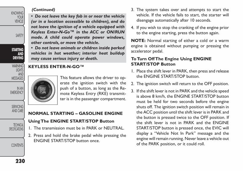
(Continued)• Do not leave the key fob in or near the vehicle(or in a location accessible to children), and donot leave the ignition of a vehicle equipped withKeyless Enter-N-Go™ in the ACC or ON/RUNmode. A child could operate power windows,other controls, or move the vehicle.• Do not leave animals or children inside parkedvehicles in hot weather; interior heat buildupmay cause serious injury or death.
KEYLESS ENTER-N-GO™
This feature allows the driver to op-erate the ignition switch with thepush of a button, as long as the Re-mote Keyless Entry (RKE) transmit-ter is in the passenger compartment.
NORMAL STARTING – GASOLINE ENGINE
UsingThe ENGINE START/STOP Button
1. The transmission must be in PARK or NEUTRAL.
2. Press and hold the brake pedal while pressing theENGINE START/STOP button once.
3. The system takes over and attempts to start thevehicle. If the vehicle fails to start, the starter willdisengage automatically after 10 seconds.
4. If you wish to stop the cranking of the engine priorto the engine starting, press the button again.
NOTE: Normal starting of either a cold or a warmengine is obtained without pumping or pressing theaccelerator pedal.
ToTurn OffThe Engine Using ENGINESTART/STOP Button
1. Place the shift lever in PARK, then press and releasethe ENGINE START/STOP button.
2. The ignition switch will return to the OFF position.
3. If the shift lever is not in PARK and the vehicle speedis above 8 km/h, the ENGINE START/STOP buttonmust be held for two seconds before the engineshuts off. The ignition switch position will remain inthe ACC position until the shift lever is in PARK andthe button is pressed twice to the OFF position. Ifthe shift lever is not in PARK and the ENGINESTART/STOP button is pressed once, the EVIC willdisplay a “Vehicle Not In Park” message and theengine will remain running. Never leave a vehicle outof the PARK position, or it could roll.
230
KNOWINGYOUR
VEHICLE
SAFETY
STARTINGAND
DRIVING
WARNINGLIGHTS
ANDMESSAGES
IN ANEMERGENCY
SERVICINGAND CARE
TECHNICALSPECIFICATIONS
CONTENTS

NOTE: If the ignition switch is left in the ACC or RUN(engine not running) position and the transmission is inPARK, the system will automatically time out after30 minutes of inactivity and the ignition will switch tothe OFF position.
ENGINE START/STOP Button Functions –With Driver’s Foot OFFThe Brake Pedal(In PARK Or NEUTRAL Position)The ENGINE START/STOP button operates similar toan ignition switch. It has four positions, OFF, ACC,RUN and START. To change the ignition switch posi-tions without starting the vehicle and use the accesso-ries follow these steps.
• Starting with the ignition switch in the OFF position:
• Press the ENGINE START/STOP button once tochange the ignition switch to the ACC position,
• Press the ENGINE START/STOP button a secondtime to change the ignition switch to the RUNposition,
• Press the ENGINE START/STOP button a third timeto return the ignition switch to the OFF position.
EXTREME COLD WEATHER (BELOW −29°C)To ensure reliable starting at these temperatures, useof an externally powered electric engine block heater isrecommended.
IF ENGINE FAILSTO START
WARNING!• Never pour fuel or other flammableliquids into the throttle body air inlet
opening in an attempt to start the vehicle.Thiscould result in a flash fire causing serious per-sonal injury.• Do not attempt to push or tow your vehicle toget it started. Unburned fuel could enter thecatalytic converter and once the engine hasstarted, ignite and damage the converter andvehicle. If the vehicle has a discharged battery,booster cables may be used to obtain a start froma booster battery or the battery in another ve-hicle.This type of start can be dangerous if doneimproperly. Refer to “Jump Starting” in “In AnEmergency” for further information.
231
KNOWINGYOURVEHICLE
SAFETY
STARTINGANDDRIVING
WARNINGLIGHTSANDMESSAGES
IN ANEMERGENCY
SERVICINGAND CARE
TECHNICALSPECIFICATIONS
CONTENTS
Clearing A Flooded Engine (Using ENGINESTART/STOP Button)If the engine fails to start after you have followed the“Normal Starting” or “Extreme Cold Weather" proce-dures, it may be flooded. To clear any excess fuel:
1. Press and hold the brake pedal.
2. Press the accelerator pedal all the way to the floorand hold it.
3. Press and release the ENGINE START/STOP buttononce.
The starter motor will engage automatically, run for10 seconds, and then disengage. Once this occurs,release the accelerator pedal and the brake pedal, wait10 to 15 seconds, then repeat the “Normal Starting”procedure.
AFTER STARTINGThe idle speed is controlled automatically and it willdecrease as the engine warms up.
NORMAL STARTING – DIESEL ENGINE
UsingThe ENGINE START/STOP Button
1. Turn the ignition switch to the ON position bypressing the ENGINE START/STOP button twice.
2. Watch the “Wait To Start Indicator Light” in theinstrument cluster. Refer to “Instrument Cluster” in“Warning Lights And Messages” for further infor-mation. It will illuminate for two to ten seconds ormore, depending on engine temperature. When the“Wait To Start Indicator Light” goes out, the engineis ready to start.
3. DO NOT press the accelerator. To start the engine,the transmission must be in PARK or NEUTRAL.Press the brake pedal (automatic transmission only)or press and hold the clutch pedal (manual transmis-sion only) while pressing and holding the ENGINESTART/STOP button. Release the button when theengine starts.
NOTE: The starter motor may need to remainengaged for up to 30 seconds in very cold conditionsuntil the engine is started. If the vehicle does not start,release the button. Wait for 25-30 seconds and thentry to start again.
4. After the engine starts, allow it to idle for approxi-mately 30 seconds before driving. This allows oil tocirculate and lubricate the turbocharger.
232
KNOWINGYOUR
VEHICLE
SAFETY
STARTINGAND
DRIVING
WARNINGLIGHTS
ANDMESSAGES
IN ANEMERGENCY
SERVICINGAND CARE
TECHNICALSPECIFICATIONS
CONTENTS

ToTurn OffThe Engine Using ENGINESTART/STOP Button
1. With the vehicle stopped, place the shift lever inNEUTRAL/PARK, then press and release the EN-GINE START/STOP button.
2. The ignition switch will return to the OFF position.
NOTE:
• If the ignition switch is left in the ACC position, thesystem will automatically time out after 30 minutesof inactivity and the ignition will switch to the OFFposition.
• If the ignition switch is left in the RUN position, thesystem will automatically time out after 30 minutesof inactivity if the vehicle speed is 0 km/h and theengine is not running.
• If the shift lever is not in PARK and the vehicle speedis above 8 km/h, the ENGINE START/STOP buttonmust be held for two seconds before the engineshuts off. The ignition switch position will remain inthe ACC position until the vehicle is stopped and thebutton is pressed twice to the OFF position.
Turbocharger “Cool Down”
NOTE: Letting the engine idle after extended opera-tion allows the turbine housing to cool to normaloperating temperature.
The following chart should be used as a guide indetermining the amount of engine idle time required tosufficiently cool down the turbocharger before shutdown, depending upon the type of driving and theamount of cargo.
TurboCharger “Cool Down” Chart
DrivingCondi-tions
Load
Turbo-charger
Tempera-ture
IdleTime(In Min-
utes)Before
Shut DownStop & Go Empty Cool Less than 1Stop & Go Medium Warm 1HighwaySpeeds
Medium Warm 2
City Traffic
MaximumGross
Combina-tion
WeightRating
Warm 3
233
KNOWINGYOURVEHICLE
SAFETY
STARTINGANDDRIVING
WARNINGLIGHTSANDMESSAGES
IN ANEMERGENCY
SERVICINGAND CARE
TECHNICALSPECIFICATIONS
CONTENTS
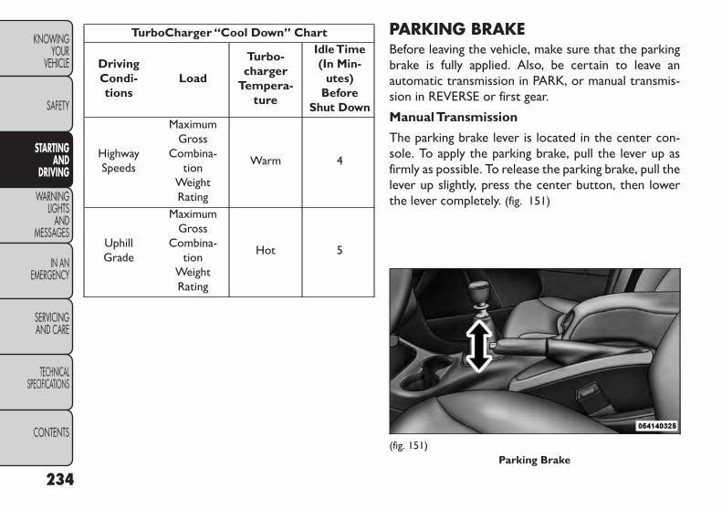
TurboCharger “Cool Down” Chart
DrivingCondi-tions
Load
Turbo-charger
Tempera-ture
IdleTime(In Min-
utes)Before
Shut Down
HighwaySpeeds
MaximumGross
Combina-tion
WeightRating
Warm 4
UphillGrade
MaximumGross
Combina-tion
WeightRating
Hot 5
PARKING BRAKEBefore leaving the vehicle, make sure that the parkingbrake is fully applied. Also, be certain to leave anautomatic transmission in PARK, or manual transmis-sion in REVERSE or first gear.
ManualTransmission
The parking brake lever is located in the center con-sole. To apply the parking brake, pull the lever up asfirmly as possible. To release the parking brake, pull thelever up slightly, press the center button, then lowerthe lever completely. (fig. 151)
(fig. 151)Parking Brake
234
KNOWINGYOUR
VEHICLE
SAFETY
STARTINGAND
DRIVING
WARNINGLIGHTS
ANDMESSAGES
IN ANEMERGENCY
SERVICINGAND CARE
TECHNICALSPECIFICATIONS
CONTENTS

AutomaticTransmission
The foot operated parking brake is located below thelower left corner of the instrument panel. To apply thepark brake, firmly push the park brake pedal fully. Torelease the parking brake, press the park brake pedal asecond time and let your foot up as you feel the brakedisengage. (fig. 152)
When the parking brake is applied with the ignitionswitch ON, the “Brake Warning Light” in the instru-ment cluster will illuminate.
NOTE:
• When the parking brake is applied and the automatictransmission is placed in gear, the “Brake WarningLight” will flash. If vehicle speed is detected, a chimewill sound to alert the driver. Fully release the park-ing brake before attempting to move the vehicle.
• This light only shows that the parking brake is ap-plied. It does not show the degree of brake applica-tion.
When parking on a hill, it is important to turn the frontwheels toward the curb on a downhill grade and awayfrom the curb on an uphill grade. For vehicles equippedwith an automatic transmission, apply the parkingbrake before placing the shift lever in PARK, otherwisethe load on the transmission locking mechanism maymake it difficult to move the shift lever out of PARK.The parking brake should always be applied wheneverthe driver is not in the vehicle.
WARNING!• Never use PARK position on an auto-matic transmission as a substitute for
the parking brake. Always apply the parkingbrake fully when parked to guard against vehiclemovement and possible injury or damage.
(Continued)(fig. 152)Parking Brake
235
KNOWINGYOURVEHICLE
SAFETY
STARTINGANDDRIVING
WARNINGLIGHTSANDMESSAGES
IN ANEMERGENCY
SERVICINGAND CARE
TECHNICALSPECIFICATIONS
CONTENTS

(Continued)• Before exiting a vehicle,always apply the park-ing brake, shift the automatic transmission intoPARK and first gear or REVERSE for a manualtransmission, and remove the key fob from theignition. When leaving the vehicle, always lockyour vehicle.• Never leave children alone in a vehicle, or withaccess to an unlocked vehicle.• Allowing children to be in a vehicle unattendedis dangerous for a number of reasons.A child orothers could be seriously or fatally injured. Chil-dren should be warned not to touch the parkingbrake, brake pedal or the shift lever.• Do not leave the key fob in or near the vehicle(or in a location accessible to children), and donot leave the ignition of a vehicle equipped withKeyless Enter-N-Go™ in the ACC or ON/RUNmode. A child could operate power windows,other controls, or move the vehicle.• Be sure the parking brake is fully disengagedbefore driving; failure to do so can lead to brakefailure and an accident.
(Continued)
(Continued)• Always fully apply the parking brake whenleaving your vehicle or it may roll and causedamage or injury. Also, be certain to leave anautomatic transmission in PARK,a manual trans-mission in REVERSE or first gear. Failure to do somay cause the vehicle to roll and cause damageor injury.
If the “Brake Warning Light” remains onwith the parking brake released, a brakesystem malfunction is indicated. Have
the brake system serviced by an authorized dealerimmediately.
236
KNOWINGYOUR
VEHICLE
SAFETY
STARTINGAND
DRIVING
WARNINGLIGHTS
ANDMESSAGES
IN ANEMERGENCY
SERVICINGAND CARE
TECHNICALSPECIFICATIONS
CONTENTS

MANUAL TRANSMISSION(for versions/markets, whereprovided)
WARNING!You or others could be injured if you leavethe vehicle unattended without having
the parking brake fully applied.The parking brakeshould always be applied when the driver is not inthe vehicle, especially on an incline.
Fully press the clutch pedal before you shift gears. Asyou release the clutch pedal, lightly press the accelera-tor pedal. (fig. 153)
Use each gear in numerical order, do not skip a gear. Besure the transmission is in first gear, (not third), whenstarting from a standing position. Damage to the clutchcan result from starting in third.
For most city driving you will find it easier to use onlythe lower gears. For steady highway driving with lightaccelerations, sixth gear is recommended.
Never drive with your foot resting on the clutch pedal,or try to hold the vehicle on a hill with the clutch pedalpartially engaged. This will cause abnormal wear on theclutch.
To shift into REVERSE, pull up on the ring just belowthe gear shift knob and then move into the REVERSE(R) position.
Never shift into REVERSE until the vehicle has come toa complete stop.
NOTE: During cold weather, until the transmissionlubricant is warm, you may experience slightly highershift efforts. This is normal and not harmful to thetransmission.
(fig. 153)Shift Pattern (Six-Speed)
237
KNOWINGYOURVEHICLE
SAFETY
STARTINGANDDRIVING
WARNINGLIGHTSANDMESSAGES
IN ANEMERGENCY
SERVICINGAND CARE
TECHNICALSPECIFICATIONS
CONTENTS

DOWNSHIFTINGProper downshifting will improve fuel economy andprolong engine life.
If you skip a gear while downshifting ordownshift at too high of a vehicle speed,these conditions may cause the engine to
overspeed if too low of a gear is selected and theclutch pedal is released.Damage to the clutch andthe transmission can result from skipping a gearwhile downshifting or downshifting at too high ofa vehicle speed even if the clutch pedal is heldpressed (i.e., not released).
To maintain a safe speed and prolong brake life, shiftdown to second or first when descending a steepgrade.
When turning a corner, or driving up a steep grade,downshift early so that the engine will not be overbur-dened.
AUTOMATIC TRANSMISSION(for versions/markets, whereprovided)
Damage to the transmission may occur ifthe following precautions are not ob-served:
• Shift into PARK only after the vehicle has cometo a complete stop.• Shift into or out of REVERSE only after thevehicle has come to a complete stop and theengine is at idle speed.• Do not shift between PARK, REVERSE, NEU-TRAL, or DRIVE when the engine is above idlespeed.• Before shifting into any gear, make sure yourfoot is firmly pressing the brake pedal.
NOTE: You must press and hold the brake pedal whileshifting out of PARK.
238
KNOWINGYOUR
VEHICLE
SAFETY
STARTINGAND
DRIVING
WARNINGLIGHTS
ANDMESSAGES
IN ANEMERGENCY
SERVICINGAND CARE
TECHNICALSPECIFICATIONS
CONTENTS

WARNING!• It is dangerous to shift out of PARK orNEUTRAL if the engine speed is higher
than idle speed. If your foot is not firmly pressingthe brake pedal, the vehicle could acceleratequickly forward or in reverse.You could lose con-trol of the vehicle and hit someone or something.Only shift into gear when the engine is idlingnormally and your foot is firmly pressing thebrake pedal.• Unintended movement of a vehicle could injurethose in or near the vehicle.As with all vehicles,you should never exit a vehicle while the engine isrunning. Before exiting a vehicle, always applythe parking brake, shift the transmission intoPARK, turn the engine off, and remove the keyfob.When the ignition is in the OFF position, thetransmission is locked in PARK, securing the ve-hicle against unwanted movement.• When leaving the vehicle, always remove thekey fob and lock your vehicle.• Never leave children alone in a vehicle, or withaccess to an unlocked vehicle.
(Continued)
(Continued)• Allowing children to be in a vehicle unattendedis dangerous for a number of reasons.A child orothers could be seriously or fatally injured. Chil-dren should be warned not to touch the parkingbrake, brake pedal or the shift lever.• Do not leave the key fob in or near the vehicle(or in a location accessible to children), and donot leave a vehicle equipped with Keyless Enter-N-Go™ in the ACC or ON/RUN mode. A childcould operate power windows, other controls, ormove the vehicle.
KEY IGNITION PARK INTERLOCKThis vehicle is equipped with a Key Ignition Park Inter-lock which requires the transmission to be in PARKbefore the engine can be turned off. This helps thedriver avoid inadvertently leaving the vehicle withoutplacing the transmission in PARK.
This system also locks the transmission in PARK when-ever the ignition switch is in the OFF position.
239
KNOWINGYOURVEHICLE
SAFETY
STARTINGANDDRIVING
WARNINGLIGHTSANDMESSAGES
IN ANEMERGENCY
SERVICINGAND CARE
TECHNICALSPECIFICATIONS
CONTENTS

Brake/Transmission Shift Interlock SystemThis vehicle is equipped with a Brake Transmission ShiftInterlock System (BTSI) that holds the shift lever inPARK unless the brakes are applied. To shift the trans-mission out of PARK, the ignition switch must beturned to the ON/RUN position (engine running ornot) and the brake pedal must be pressed.
Four-Speed or Six-Speed AutomaticTransmissionThe transmission gear position display (located in theinstrument cluster) indicates the transmission gearrange. You must press the brake pedal to move the shiftlever out of PARK (refer to “Brake/Transmission ShiftInterlock System” in this section). To drive, move theshift lever from PARK or NEUTRAL to the DRIVEposition.
The electronically-controlled transmission provides aprecise shift schedule. The transmission electronics areself-calibrating; therefore, the first few shifts on a newvehicle may be somewhat abrupt. This is a normalcondition, and precision shifts will develop within a fewhundred kilometers.
Only shift from DRIVE to PARK or REVERSE when theaccelerator pedal is released and the vehicle is stopped.Be sure to keep your foot on the brake pedal whenshifting between these gears.
The transmission shift lever has PARK, REVERSE,NEUTRAL, DRIVE, and AutoStick® shift positions.Manual shifts can be made using the AutoStick® shiftcontrol (refer to “AutoStick®” in this section for fur-ther information). Moving the shift lever into theAutoStick® (+/-) position (below the Drive position)activates Autostick® mode, providing manual shiftcontrol and displaying the current gear in the instru-ment cluster. (fig. 154)
(fig. 154)Shift Lever
240
KNOWINGYOUR
VEHICLE
SAFETY
STARTINGAND
DRIVING
WARNINGLIGHTS
ANDMESSAGES
IN ANEMERGENCY
SERVICINGAND CARE
TECHNICALSPECIFICATIONS
CONTENTS

Gear RangesDO NOT race the engine when shifting from PARK orNEUTRAL into another gear range.
NOTE: After selecting any gear range, wait a momentto allow the selected gear to engage before accelerat-ing. This is especially important when the engine iscold.
PARK (P)This range supplements the parking brake by lockingthe transmission. The engine can be started in thisrange. Never attempt to use PARK while the vehicle isin motion. Apply the parking brake when leaving thevehicle in this range.
When parking on a level surface, you may shift thetransmission into PARK first, and then apply the park-ing brake.
When parking on a hill, apply the parking brake beforeshifting the transmission to PARK, otherwise the loadon the transmission locking mechanism may make itdifficult to move the shift lever out of PARK. As anadded precaution, turn the front wheels toward thecurb on a downhill grade and away from the curb on anuphill grade.
WARNING!• Never use the PARK position as a sub-stitute for the parking brake.Always ap-
ply the parking brake fully when parked to guardagainst vehicle movement and possible injury ordamage.• Your vehicle could move and injure you andothers if it is not completely in PARK. Check bytrying to move the shift lever out of PARK withthe brake pedal released. Make sure the trans-mission is in PARK before leaving the vehicle.• It is dangerous to shift out of PARK or NEU-TRAL if the engine speed is higher than idlespeed. If your foot is not firmly pressing the brakepedal, the vehicle could accelerate quickly for-ward or in reverse.You could lose control of thevehicle and hit someone or something. Only shiftinto gear when the engine is idling normally andyour foot is firmly pressing the brake pedal.
(Continued)
241
KNOWINGYOURVEHICLE
SAFETY
STARTINGANDDRIVING
WARNINGLIGHTSANDMESSAGES
IN ANEMERGENCY
SERVICINGAND CARE
TECHNICALSPECIFICATIONS
CONTENTS
(Continued)• Unintended movement of a vehicle could injurethose in or near the vehicle.As with all vehicles,you should never exit a vehicle while the engine isrunning. Before exiting a vehicle, always applythe parking brake, shift the transmission intoPARK, turn the engine OFF, and remove the keyfob.When the ignition is in the OFF position, thetransmission is locked in the PARK, securing thevehicle against unwanted movement.• When leaving the vehicle, always remove thekey fob and lock your vehicle.• Never leave children alone in a vehicle, or withaccess to an unlocked vehicle. Allowing childrento be in a vehicle unattended is dangerous for anumber of reasons. A child or others could beseriously or fatally injured. Children should bewarned not to touch the parking brake, brakepedal or the shift lever. Do not leave the key fobin or near the vehicle (or in a location accessibleto children), and do not leave the ignition of avehicle equipped with Keyless Enter-N-Go™ intheACC or ON/RUN mode.A child could operatepower windows, other controls, or move the ve-hicle.
• Before moving the shift lever out ofPARK, you must turn the ignition switchfrom the LOCK/OFF position to the ON/
RUN position, and also press the brake pedal.Otherwise, damage to the shift lever could result.• DO NOT race the engine when shifting fromPARK or NEUTRAL into another gear range, asthis can damage the drivetrain.
The following indicators should be used to ensure thatyou have engaged the transmission into the PARKposition:
• When shifting into PARK, firmly move the shift leverall the way forward and to the left until it stops and isfully seated.
• Look at the transmission gear position display andverify that it indicates the PARK position.
• With brake pedal released, verify that the shift leverwill not move out of PARK.
242
KNOWINGYOUR
VEHICLE
SAFETY
STARTINGAND
DRIVING
WARNINGLIGHTS
ANDMESSAGES
IN ANEMERGENCY
SERVICINGAND CARE
TECHNICALSPECIFICATIONS
CONTENTS

REVERSE (R)This range is for moving the vehicle backward. Shift intoREVERSE only after the vehicle has come to a completestop.
NEUTRAL (N)Use this range when the vehicle is standing for pro-longed periods with the engine running. The enginemay be started in this range. Apply the parking brakeand shift the transmission into PARK if you must leavethe vehicle.
WARNING!Do not coast in NEUTRAL and neverturn off the ignition to coast down a hill.
These are unsafe practices that limit your re-sponse to changing traffic or road conditions.Youmight lose control of the vehicle and have acollision.
Towing the vehicle, coasting, or drivingfor any other reason with the transmis-sion in NEUTRAL can result in severe
transmission damage.Refer to“RecreationalTow-ing” in “Starting and Driving” and “Towing A Dis-abled Vehicle” in “In An Emergency” for furtherinformation.
DRIVE (D)This range should be used for most city and highwaydriving. It provides the smoothest upshifts and down-shifts, and the best fuel economy. The transmissionautomatically upshifts through all forward gears. TheDRIVE position provides optimum driving characteris-tics under all normal operating conditions.
When frequent transmission shifting occurs (such aswhen operating the vehicle under heavy loading condi-tions, in hilly terrain, traveling into strong head winds,or while towing heavy trailers), use the AutoStick®shift control (refer to “AutoStick®” in this section forfurther information) to select a lower gear. Underthese conditions, using a lower gear will improve per-formance and extend transmission life by reducingexcessive shifting and heat buildup.
If the transmission temperature exceeds normal oper-ating limits, the powertrain controller will modify thetransmission shift schedule and expand the range oftorque converter clutch engagement. This is done toprevent transmission damage due to overheating.
243
KNOWINGYOURVEHICLE
SAFETY
STARTINGANDDRIVING
WARNINGLIGHTSANDMESSAGES
IN ANEMERGENCY
SERVICINGAND CARE
TECHNICALSPECIFICATIONS
CONTENTS

During cold temperatures, transmission operation maybe modified depending on engine and transmissiontemperature as well as vehicle speed. This featureimproves warm up time of the engine and transmissionto achieve maximum efficiency. Engagement of thetorque converter clutch is inhibited until the transmis-sion fluid is warm (refer to the “Note” under “TorqueConverter Clutch” in this section). During extremelycold temperatures -27°C or below, operation maybriefly be limited to only second gear (for four-speedtransmission) or third gear (for six-speed transmis-sion). Normal operation will resume once the trans-mission temperature has risen to a suitable level.
Transmission Limp Home ModeTransmission function is monitored electronically forabnormal conditions. If a condition is detected thatcould result in transmission damage, TransmissionLimp Home Mode is activated. In this mode, the trans-mission remains in second gear (for four-speed trans-mission) or third gear (for six-speed transmission)regardless of which forward gear is selected. PARK,REVERSE, and NEUTRAL will continue to operate.The Malfunction Indicator Light (MIL) may be illumi-nated. Limp Home Mode allows the vehicle to bedriven to an authorized dealer for service withoutdamaging the transmission.
In the event of a momentary problem, the transmissioncan be reset to regain all forward gears by performingthe following steps:
1. Stop the vehicle.
2. Shift the transmission into PARK.
3. Turn the ignition switch to the LOCK/OFF position.
4. Wait approximately 10 seconds.
5. Restart the engine.
6. Shift into the desired gear range. If the problem is nolonger detected, the transmission will return tonormal operation.
NOTE: Even if the transmission can be reset, werecommend that you visit your authorized dealer atyour earliest possible convenience. Your authorizeddealer has diagnostic equipment to determine if theproblem could recur.
If the transmission cannot be reset, authorized dealerservice is required.
Overdrive OperationThe automatic transmission includes an electronicallycontrolled Overdrive (top gear). The transmission willautomatically shift into Overdrive if the following con-ditions are present:
• The shift lever is in the DRIVE position.
244
KNOWINGYOUR
VEHICLE
SAFETY
STARTINGAND
DRIVING
WARNINGLIGHTS
ANDMESSAGES
IN ANEMERGENCY
SERVICINGAND CARE
TECHNICALSPECIFICATIONS
CONTENTS

• The transmission fluid has reached an adequate tem-perature.
• The engine coolant has reached an adequate tem-perature.
• The vehicle speed is sufficiently high and the driver isnot heavily pressing the accelerator.
Torque Converter ClutchA feature designed to improve fuel economy has beenincluded in the automatic transmission on your vehicle.A clutch within the torque converter engages auto-matically at calibrated speeds. This may result in aslightly different feeling or response during normaloperation in the upper gears. When the vehicle speeddrops or during some accelerations, the clutch auto-matically disengages.
NOTE: The torque converter clutch will not engageuntil the transmission fluid and engine coolant arewarm (usually after 2 to 5 km of driving). Because theengine speed is higher when the torque converterclutch is not engaged, it may seem as if the transmissionis not shifting into Overdrive when cold. This is normal.Using the AutoStick® shift control, when the transmis-sion is sufficiently warm, will demonstrate that thetransmission is able to shift into and out of Overdrive.
AUTOSTICK® (for versions/markets, where provided)AutoStick® is a driver-interactive transmission featureproviding manual shift control, giving you more controlof the vehicle. AutoStick® allows you to maximizeengine braking, eliminate undesirable upshifts anddownshifts, and improve overall vehicle performance.
This system can also provide you with more controlduring passing, city driving, cold slippery conditions,mountain driving, trailer towing, and many other situ-ations.
OperationWhen the shift lever is in the AutoStick® position(below the DRIVE position), it can be moved from sideto side. This allows the driver to manually select thetransmission gear being used. Moving the shift lever tothe left (-) triggers a downshift and to the right (+) anupshift. The current gear will be displayed in the instru-ment cluster.
245
KNOWINGYOURVEHICLE
SAFETY
STARTINGANDDRIVING
WARNINGLIGHTSANDMESSAGES
IN ANEMERGENCY
SERVICINGAND CARE
TECHNICALSPECIFICATIONS
CONTENTS
In AutoStick® mode, the transmission will shift up ordown when the driver moves the shift lever to the right(+) or left (-), unless an engine lugging or overspeedcondition would result. It will remain in the selectedgear until another upshift or downshift is chosen,except as described below.
• The transmission will automatically upshift whennecessary to prevent engine over-speed.
• The transmission will automatically downshift as thevehicle slows (to prevent engine lugging) and willdisplay the current gear.
• The transmission will automatically downshift to firstgear when coming to a stop. After a stop, the drivershould manually upshift (+) the transmission as thevehicle is accelerated.
• You can start out, from a stop, in any gear except topgear. Tapping (+) (at a stop) will allow starting insecond gear. Starting out in second gear is helpful insnow or icy conditions.
• If a requested downshift would cause the engine toover-speed, that shift will not occur.
• Avoid using speed control when AutoStick® is en-gaged.
• Transmission shifting will be more noticeable whenAutoStick® is engaged.
• The system may revert to automatic shift mode if afault or overheat condition is detected.
To disengage AutoStick® mode, return the shift leverto the DRIVE position. You can shift in or out of theAutoStick® position at any time without taking yourfoot off the accelerator pedal.
WARNING!Do not downshift for additional enginebraking on a slippery surface.The drive
wheels could lose their grip and the vehicle couldskid, causing a collision or personal injury.
246
KNOWINGYOUR
VEHICLE
SAFETY
STARTINGAND
DRIVING
WARNINGLIGHTS
ANDMESSAGES
IN ANEMERGENCY
SERVICINGAND CARE
TECHNICALSPECIFICATIONS
CONTENTS

ALL WHEEL DRIVE (AWD)(for versions/markets, whereprovided)This feature provides on-demand All-Wheel Drive(AWD). The system is automatic with no driver inputsor additional driving skills required. Under normaldriving conditions, the front wheels provide most ofthe traction. If the front wheels begin to lose traction,power is shifted automatically to the rear wheels. Thegreater the front wheel traction loss, the greater thepower transfer to the rear wheels.
Additionally, on dry pavement under heavy throttleinput (where one may have no wheel spin), torque willbe sent to the rear in a pre-emptive effort to improvevehicle launch and performance characteristics.
All wheels must have the same size andtype tires. Unequal tire sizes must not beused. Unequal tire size may cause failure
of the power transfer unit.
DRIVING ON SLIPPERY SURFACESACCELERATIONRapid acceleration on snow covered, wet, or otherslippery surfaces may cause the driving wheels to pullerratically to the right or left. This phenomenon occurswhen there is a difference in the surface traction underthe front (driving) wheels.
WARNING!Rapid acceleration on slippery surfacesis dangerous. Unequal traction can
cause sudden pulling of the front wheels. Youcould lose control of the vehicle and possiblyhave a collision. Accelerate slowly and carefullywhenever there is likely to be poor traction (ice,snow, wet, mud, loose sand, etc.).
247
KNOWINGYOURVEHICLE
SAFETY
STARTINGANDDRIVING
WARNINGLIGHTSANDMESSAGES
IN ANEMERGENCY
SERVICINGAND CARE
TECHNICALSPECIFICATIONS
CONTENTS

TRACTIONWhen driving on wet or slushy roads, it is possible fora wedge of water to build up between the tire and roadsurface. This is hydroplaning and may cause partial orcomplete loss of vehicle control and stopping ability. Toreduce this possibility, the following precautions shouldbe observed:
1. Slow down during rainstorms or when the roads areslushy.
2. Slow down if the road has standing water orpuddles.
3. Replace the tires when tread wear indicators firstbecome visible.
4. Keep tires properly inflated.
5. Maintain sufficient distance between your vehicleand the vehicle in front of you to avoid a collision ina sudden stop.
DRIVING THROUGH WATERDriving through water more than a few centimetersdeep will require extra caution to ensure safety andprevent damage to your vehicle.
FLOWING/RISING WATER
WARNING!Do not drive on, or cross, a road or apath where water is flowing and/or rising
(as in storm run-off). Flowing water can wearaway the road or path's surface and cause yourvehicle to sink into deeper water. Furthermore,flowing and/or rising water can carry your vehicleaway swiftly. Failure to follow this warning mayresult in injuries that are serious or fatal to you,your passengers, and others around you.
Shallow Standing WaterAlthough your vehicle is capable of driving throughshallow standing water, consider the following Cautionand Warning before doing so.
248
KNOWINGYOUR
VEHICLE
SAFETY
STARTINGAND
DRIVING
WARNINGLIGHTS
ANDMESSAGES
IN ANEMERGENCY
SERVICINGAND CARE
TECHNICALSPECIFICATIONS
CONTENTS
• Always check the depth of the standingwater before driving through it. Neverdrive through standing water that is
deeper than the bottom of the tire rims mountedon the vehicle.• Determine the condition of the road or the paththat is under water and if there are any obstaclesin the way before driving through the standingwater.• Do not exceed 8 km/h when driving throughstanding water.This will minimize wave effects.• Driving through standing water may causedamage to your vehicle’s drivetrain components.Always inspect your vehicle’s fluids (i.e., engineoil, transmission, axle, etc.) for signs of contami-nation (i.e., fluid that is milky or foamy in appear-ance) after driving through standing water.Do notcontinue to operate the vehicle if any fluid ap-pears contaminated, as this may result in furtherdamage. Such damage is not covered by the NewVehicle LimitedWarranty.• Getting water inside your vehicle’s engine cancause it to lock up and stall out,and cause seriousinternal damage to the engine. Such damage isnot covered by the NewVehicle LimitedWarranty.
WARNING!• Driving through standing water limitsyour vehicle’s traction capabilities. Do
not exceed 8 km/h when driving through standingwater.• Driving through standing water limits your ve-hicle’s braking capabilities, which increases stop-ping distances. Therefore, after driving throughstanding water, drive slowly and lightly press onthe brake pedal several times to dry the brakes.• Getting water inside your vehicle’s engine cancause it to lock up and stall out, and leave youstranded.• Failure to follow these warnings may result ininjuries that are serious or fatal to you, yourpassengers, and others around you.
249
KNOWINGYOURVEHICLE
SAFETY
STARTINGANDDRIVING
WARNINGLIGHTSANDMESSAGES
IN ANEMERGENCY
SERVICINGAND CARE
TECHNICALSPECIFICATIONS
CONTENTS

TRAILER TOWINGIn this section you will find safety tips and informationon limits to the type of towing you can reasonably dowith your vehicle. Before towing a trailer, carefullyreview this information to tow your load as efficientlyand safely as possible.
To maintain the New Vehicle Limited Warranty cover-age, follow the requirements and recommendations inthis manual concerning vehicles used for trailer towing.
COMMONTOWING DEFINITIONSThe following trailer towing related definitions willassist you in understanding the following information:
GrossVehicle Weight Rating (GVWR)The GVWR is the total allowable weight of yourvehicle. This includes driver, passengers, cargo, andtongue weight. The total load must be limited so thatyou do not exceed the GVWR.
GrossTrailer Weight (GTW)The GTW is the weight of the trailer plus the weight ofall cargo, consumables and equipment (permanent ortemporary) loaded in or on the trailer in its "loaded andready for operation" condition. The recommended wayto measure GTW is to put your fully loaded trailer ona vehicle scale. The entire weight of the trailer must besupported by the scale.
Gross Combination Weight Rating (GCWR)The GCWR is the total permissible weight of yourvehicle and trailer when weighed in combination.
NOTE: The GCWR rating includes a 68 kg allowancefor the presence of a driver.
Gross Axle Weight Rating (GAWR)The GAWR is the maximum capacity of the front andrear axles. Distribute the load over the front and rearaxles evenly. Make sure that you do not exceed eitherfront or rear GAWR.
WARNING!It is important that you do not exceedthe maximum front or rear GAWR. A
dangerous driving condition can result if eitherrating is exceeded.You could lose control of thevehicle and have an accident.
250
KNOWINGYOUR
VEHICLE
SAFETY
STARTINGAND
DRIVING
WARNINGLIGHTS
ANDMESSAGES
IN ANEMERGENCY
SERVICINGAND CARE
TECHNICALSPECIFICATIONS
CONTENTS

Tongue Weight (TW)The tongue weight is the downward force exerted onthe hitch ball by the trailer. In most cases, it should notbe less than 7% or more than 10% of the trailer load.Tongue weight must not exceed the lesser of either thehitch certification rating, or the trailer tongue chassisrating. It should never be less than 4% of the trailerload, and not less than 25 kg. You must consider tongueload as part of the load on your vehicle and its’ GAWR.
WARNING!An improperly adjusted hitch systemmay reduce handling, stability and brak-
ing performance and could result in an accident.Consult with your hitch and trailer manufactureror a reputable trailer/dealer for additional infor-mation.
Frontal AreaThe frontal area is the maximum height multiplied bythe maximum width of the front of a trailer.
Trailer Sway ControlRefer to “TSC (Trailer Sway Control)” under “KnowingYour Vehicle/Electronic Brake Control System” forfurther information.
BREAKAWAY CABLE ATTACHMENTEuropean braking regulations for braked trailers up to3,500 kg require trailers to be fitted with either asecondary coupling or breakaway cable.
The recommended location for attaching the normaltrailer's breakaway cable is in the stamped slot locatedon the sidewall of the hitch receiver.
With Attachment Point
• For detachable tow bar, pass the cable through theattachment point and clip it back onto itself. (fig. 155)
(fig. 155)Detachable Ball Clip Loop Method
251
KNOWINGYOURVEHICLE
SAFETY
STARTINGANDDRIVING
WARNINGLIGHTSANDMESSAGES
IN ANEMERGENCY
SERVICINGAND CARE
TECHNICALSPECIFICATIONS
CONTENTS

• For fixed ball tow bar, attach the clip directly to thedesignated point. This alternative must be specificallypermitted by the trailer manufacturer since the clipmay not be sufficiently strong for use in the way.
(fig. 156)
Without Attachment Points
• For detachable ball tow bar, you must follow therecommended manufacturer or supplier procedure.
(fig. 157)
• For fixed ball tow bar, loop the cable around the neckof the tow ball. If you fit the cable like this, use a singleloop only. (fig. 158)
(fig. 156)Fixed Ball Clip Loop Method
(fig. 157)Detachable Ball Neck Loop Method
(fig. 158)Fixed Ball Neck Loop Method
252
KNOWINGYOUR
VEHICLE
SAFETY
STARTINGAND
DRIVING
WARNINGLIGHTS
ANDMESSAGES
IN ANEMERGENCY
SERVICINGAND CARE
TECHNICALSPECIFICATIONS
CONTENTS

TRAILERTOWING WEIGHTS (MAXIMUMTRAILER WEIGHT RATINGS)The following chart provides the maximum trailer weight ratings towable for your given drivetrain.
Engine/Transmission Frontal Area Max. GTW(GrossTrailer Wt.)(5 and 7 Passenger
Model
Max.Tongue Wt. ♦(5 and 7 Passenger
Model)
2.4L/Automatic 2.0 sq m 454 kg 22 kg3.6L/Automatic 3.7 sq m 1,100 kg 55 kg
2.0L Diesel/Manual 3.7 sq m 1,250 kg 62 kg2.0L Diesel/Automatic 3.7 sq m 1,100 kg 55 kg
Refer to local laws for maximum trailer towing speeds♦ The trailer tongue weight must be considered as part of the combined weight of occupants and cargo and it shouldnever exceed the weight referenced on the Tire and Loading Information placard.
TRAILER ANDTONGUE WEIGHTLoads balanced over the wheels or heavier in the rearcan cause the trailer to sway severely side to sidewhich will cause loss of control of the vehicle andtrailer. Failure to load trailers heavier in front is thecause of many trailer accidents.
Never exceed the maximum tongue weight stampedon your trailer hitch.
Consider the following items when computing theweight on the rear axle of the vehicle:
• The tongue weight of the trailer.
• The weight of any other type of cargo or equipmentput in or on your vehicle.
• The weight of the driver and all passengers.
NOTE: Remember that everything put into or on thetrailer adds to the load on your vehicle. Also, additionalfactory-installed options or dealer-installed optionsmust be considered as part of the total load on yourvehicle. Refer to the Tire and Loading Informationplacard, located on the face of the driver's door or onthe driver's side “B” pillar, for the maximum combinedweight of occupants and cargo for your vehicle.
253
KNOWINGYOURVEHICLE
SAFETY
STARTINGANDDRIVING
WARNINGLIGHTSANDMESSAGES
IN ANEMERGENCY
SERVICINGAND CARE
TECHNICALSPECIFICATIONS
CONTENTS
TOWING REQUIREMENTSTo promote proper break-in of your new vehicle drive-train components the following guidelines are recom-mended:
• Do not tow a trailer at all during thefirst 805 km the new vehicle is driven.Theengine,axle or other parts could be dam-
aged.• Then, during the first 805 km that a trailer istowed,do not drive over 80 km/h and do not makestarts at full throttle.This helps the engine andother parts of the vehicle wear in at the heavierloads.
Perform the maintenance listed in the MaintenanceSchedule. When towing a trailer, never exceed theGAWR ratings.
WARNING!Improper towing can lead to an injuryaccident. Follow these guidelines to
make your trailer towing as safe as possible:• Make certain that the load is secured in thetrailer and that it will not shift during travel.When trailering cargo that is not fully secured,dynamic load shifts can occur that may be diffi-cult for the driver to control.You could lose con-trol of your vehicle and have an accident.• All trailer hitches should be professionally in-stalled on your vehicle.• When hauling cargo or towing a trailer, do notoverload your vehicle or trailer. Overloading cancause a loss of control, poor performance, ordamage to brakes, axle, engine, transmission,steering, suspension, chassis structure, or tires.• Safety chains must always be used betweenyour vehicle and trailer. Always connect thechains to the frame or hook retainers of thevehicle hitch. Cross the chains under the trailertongue and allow enough slack for turning cor-ners.
(Continued)
254
KNOWINGYOUR
VEHICLE
SAFETY
STARTINGAND
DRIVING
WARNINGLIGHTS
ANDMESSAGES
IN ANEMERGENCY
SERVICINGAND CARE
TECHNICALSPECIFICATIONS
CONTENTS

(Continued)• Vehicles with trailers should not be parked on agrade.When parking, apply the parking brake onthe tow vehicle. Always, block or "chock" thetrailer wheels.• GCWR must not be exceeded.• Total weight must be distributed between thetow vehicle and the trailer such that the followingfour ratings are not exceeded:
1. GVWR
2. GTW
3. GAWR
4. Tongue weight rating for the trailer hitch uti-lized.
Towing Requirements –Tires
– Do not attempt to tow a trailer while using acompact spare tire.
– Proper tire inflation pressures are essential for thesafe and satisfactory operation of your vehicle. Referto “Tires – General Information” in “Technical Speci-fications” for proper tire inflation procedures.
– Check the trailer tires for proper tire inflation pres-sures before trailer usage.
– Check for signs of tire wear or visible tire damagebefore towing a trailer. Refer to “Tires – GeneralInformation” in “Technical Specifications” for theproper tire inspection procedures.
– When replacing tires, refer to “Tires – GeneralInformation” in “Technical Specifications” for propertire replacement procedures. Replacing tires with ahigher load carrying capacity will not increase thevehicle's GVWR and GAWR limits.
Towing Requirements –Trailer Brakes
– Do not interconnect the hydraulic brake system orvacuum system of your vehicle with that of thetrailer. This could cause inadequate braking and pos-sible personal injury.
– When towing a trailer equipped with a hydraulicsurge actuated brake system, an electronic brakecontroller is not required.
– Trailer brakes are recommended for trailers over450 kg and required for trailers in excess of 750 kg.
If the trailer weighs more than 450 kgloaded, it should have its own brakes,andthey should be of adequate capacity.Fail-
ure to do this could lead to accelerated brakelining wear, higher brake pedal effort, and longerstopping distances.
255
KNOWINGYOURVEHICLE
SAFETY
STARTINGANDDRIVING
WARNINGLIGHTSANDMESSAGES
IN ANEMERGENCY
SERVICINGAND CARE
TECHNICALSPECIFICATIONS
CONTENTS

WARNING!• Do not connect trailer brakes to yourvehicle's hydraulic brake lines. It can
overload your brake system and cause it to fail.You might not have brakes when you need themand could have an accident.• Towing any trailer will increase your stoppingdistance.When towing, you should allow for ad-ditional space between your vehicle and the ve-hicle in front of you. Failure to do so could resultin an accident.
Towing Requirements –Trailer Lights AndWiringWhenever you pull a trailer, regardless of the trailersize, stoplights and turn signals on the trailer arerequired for motoring safety.
The Trailer Tow Package may include a seven-pin or athirteen-pin wiring harness. Use a factory approvedtrailer harness and connector.
NOTE: Do not cut or splice wiring into the vehicleswiring harness.
The electrical connections are all complete to thevehicle but you must mate the harness to a trailerconnector. (fig. 159)
(fig. 159)Seven-Pin Connector
256
KNOWINGYOUR
VEHICLE
SAFETY
STARTINGAND
DRIVING
WARNINGLIGHTS
ANDMESSAGES
IN ANEMERGENCY
SERVICINGAND CARE
TECHNICALSPECIFICATIONS
CONTENTS

Pin Number Function Wire Color1 Left Turn Signal Yellow2 Rear Fog Light Blue3 Ground/
CommonReturn
White
4 Right Turn Signal Green5 Right Rear
Position, SideMarker Lights,and Rear Regis-
tration PlateIlluminationDevice. b
Brown
Pin Number Function Wire Color6 Stoplights Red7 Left Rear
Position, SideMarker Lights,and Rear Regis-
tration PlateIlluminationDevice. b
Black
b The rear position registration plate illumination deviceshall be connected such that no light of the device has acommon connection with both pins 5 and 7.
(fig. 160)
(fig. 160)Thirteen-Pin Connector
257
KNOWINGYOURVEHICLE
SAFETY
STARTINGANDDRIVING
WARNINGLIGHTSANDMESSAGES
IN ANEMERGENCY
SERVICINGAND CARE
TECHNICALSPECIFICATIONS
CONTENTS

Pin Number Function Wire Color1 Left Turn Signal Yellow2 Rear Fog Light Blue
3 a Ground/CommonReturn for
Contacts (Pins)1 and 2 and
4 to 8
White
4 Right Turn Signal Green5 Right Rear
Position, SideMarker Lights,and Rear Regis-
tration PlateIlluminationDevice. b
Brown
6 Stoplights Red7 Left Rear
Position, SideMarker Lights,and Rear Regis-
tration PlateIlluminationDevice. b
Black
Pin Number Function Wire Color8 Reverse lights Red/Black9 Permanent
Power Supply(+12V)
Brown/White
10 Power SupplyControlled byIgnition Switch
(+12V)
Red
11 a Return forContact (Pin) 10
White
12 Reserve forFuture
Allocation
Red/Blue
13 a Return forContact (Pin) 9
White
Note: The allocation pin 12 has been changed from“Coding for coupled Trailer” to “Reserve for FutureAllocation.”a The three return circuits shall not be connectedelectrically in the trailer.b The rear position registration plate illumination deviceshall be connected such that no light of the device has acommon connection with both pins 5 and 7.
258
KNOWINGYOUR
VEHICLE
SAFETY
STARTINGAND
DRIVING
WARNINGLIGHTS
ANDMESSAGES
IN ANEMERGENCY
SERVICINGAND CARE
TECHNICALSPECIFICATIONS
CONTENTS

TOWINGTIPSBefore setting out on a trip, practice turning, stopping,and backing up the trailer in an area located away fromheavy traffic.
ManualTransmission (for versions/markets,where provided)If using a manual transmission vehicle for trailer towing,all starts must be in FIRST gear to avoid clutch slippage.
AutomaticTransmission (for versions/markets,where provided)The DRIVE range can be selected when towing. How-ever, if frequent shifting occurs while in DRIVE, use theAutoStick® shift control to manually select a lowergear.
NOTE: Using a lower gear while operating the vehicleunder heavy loading conditions will improve perfor-mance and extend transmission life by reducing exces-sive shifting and heat build up. This action will alsoprovide better engine braking.
If you REGULARLY tow a trailer for more than 45 min-utes of continuous operation, then change the trans-mission fluid and automatic transmission filter as speci-fied for “police, taxi, fleet, or frequent trailer towing.”Refer to the “Maintenance Schedule” for the propermaintenance intervals.
NOTE: Check the transmission fluid level (four-speedtransmission only) before towing. The six-speed trans-mission does not require a fluid level check beforetowing. If, however, you notice fluid leakage or trans-mission malfunction, see your authorized dealer imme-diately for assistance.
Electronic Speed Control (for versions/markets, where provided)
• Do not use in hilly terrain or with heavy loads.
• When using the speed control, if you experiencespeed drops greater than 16 km/h, disengage untilyou can get back to cruising speed.
• Use speed control in flat terrain and with light loadsto maximize fuel efficiency.
AutoStick®
• When using the AutoStick® shift control, select thehighest gear that allows for adequate performanceand avoids frequent downshifts. For example, choose“4” if the desired speed can be maintained. Choose“3” or “2” if needed to maintain the desired speed.
• To prevent excess heat generation, avoid continuousdriving at high RPM. Reduce vehicle speed as neces-sary to avoid extended driving at high RPM. Returnto a higher gear or vehicle speed when grade androad conditions allow.
259
KNOWINGYOURVEHICLE
SAFETY
STARTINGANDDRIVING
WARNINGLIGHTSANDMESSAGES
IN ANEMERGENCY
SERVICINGAND CARE
TECHNICALSPECIFICATIONS
CONTENTS
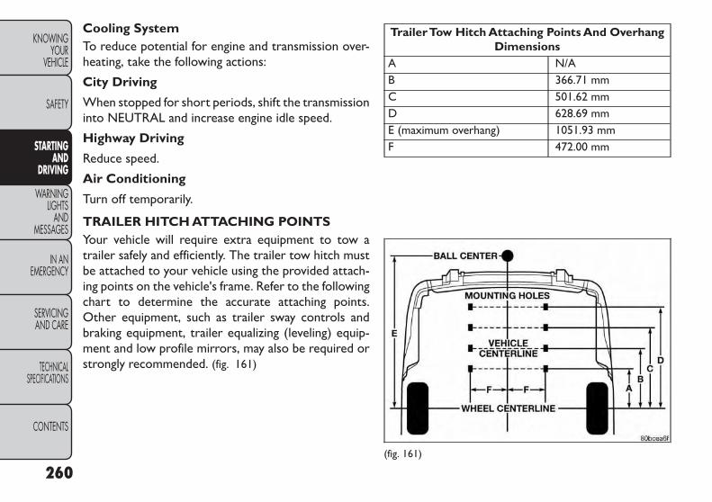
Cooling SystemTo reduce potential for engine and transmission over-heating, take the following actions:
City Driving
When stopped for short periods, shift the transmissioninto NEUTRAL and increase engine idle speed.
Highway Driving
Reduce speed.
Air Conditioning
Turn off temporarily.
TRAILER HITCH ATTACHING POINTSYour vehicle will require extra equipment to tow atrailer safely and efficiently. The trailer tow hitch mustbe attached to your vehicle using the provided attach-ing points on the vehicle's frame. Refer to the followingchart to determine the accurate attaching points.Other equipment, such as trailer sway controls andbraking equipment, trailer equalizing (leveling) equip-ment and low profile mirrors, may also be required orstrongly recommended. (fig. 161)
TrailerTow Hitch Attaching Points And OverhangDimensions
A N/AB 366.71 mmC 501.62 mmD 628.69 mmE (maximum overhang) 1051.93 mmF 472.00 mm
(fig. 161)
260
KNOWINGYOUR
VEHICLE
SAFETY
STARTINGAND
DRIVING
WARNINGLIGHTS
ANDMESSAGES
IN ANEMERGENCY
SERVICINGAND CARE
TECHNICALSPECIFICATIONS
CONTENTS

RECREATIONAL TOWING (BEHIND MOTORHOME, ETC.)TOWINGTHISVEHICLE BEHIND ANOTHERVEHICLE
TowingCondition
Wheels OFFthe Ground
FWD MODELS MANUALTRANSMISSION
FWD MODELSAUTOMATIC
TRANSMISSIONAWD MODELS
Flat Tow NONE• Transmission in NEUTRAL
• Ignition in ACC or ON/RUNposition
NOT ALLOWED NOT ALLOWED
Wheel Lift orDolly Tow
Rear NOT ALLOWED NOT ALLOWED NOT ALLOWEDFront OK OK NOT ALLOWED
Flatbed ALL BEST METHOD BEST METHOD OK
All-Wheel Drive (AWD) Models
Recreational towing (with all four wheels on theground, or using a towing dolly) is NOT ALLOWED.The only acceptable method for towing this vehicle(behind another vehicle) is on a vehicle trailer with allfour wheels OFF the ground.
Towing this vehicle with ANY of itswheels on the ground can cause severetransmission and/or power transfer unit
damage. Damage from improper towing is notcovered under the NewVehicle LimitedWarranty.
Front-Wheel Drive (FWD) Models - ManualTransmission
Front-wheel drive vehicles with manual transmis-sions may be flat towed (with all four wheels on theground) at any legal highway speed, for any distance, ifthe manual transmission is in NEUTRAL and theignition is in the ACC or ON/RUN position.
These vehicles may also be towed using a tow dolly(with the front wheels OFF the ground), or on a flatbedor vehicle trailer (with all four wheels OFF the ground).
261
KNOWINGYOURVEHICLE
SAFETY
STARTINGANDDRIVING
WARNINGLIGHTSANDMESSAGES
IN ANEMERGENCY
SERVICINGAND CARE
TECHNICALSPECIFICATIONS
CONTENTS

Failure to follow these towing methodscan cause severe engine and/or transmis-sion damage. Damage from improper
towing is not covered under the NewVehicle Lim-itedWarranty.
Front-Wheel Drive (FWD) Models - AutomaticTransmission
DO NOT flat tow any vehicle equippedwith an automatic transmission.Damageto the drivetrain will result. If these ve-
hicles require towing, make sure all drive wheelsare OFF the ground.
NOTE: This vehicle may be towed on a flatbed orvehicle trailer provided all four wheels are OFF theground.
This vehicle may also be towed using a tow dolly (withthe front wheels OFF the ground).
Towing this vehicle in violation of theabove requirements can cause severetransmission damage. Damage from
improper towing is not covered under the NewVehicle LimitedWarranty.
262
KNOWINGYOUR
VEHICLE
SAFETY
STARTINGAND
DRIVING
WARNINGLIGHTS
ANDMESSAGES
IN ANEMERGENCY
SERVICINGAND CARE
TECHNICALSPECIFICATIONS
CONTENTS

WARNING LIGHTS AND MESSAGESINSTRUMENT CLUSTER(fig. 162)
(fig. 162)
263
KNOWINGYOURVEHICLE
SAFETY
STARTINGANDDRIVING
WARNINGLIGHTSANDMESSAGES
IN ANEMERGENCY
SERVICINGAND CARE
TECHNICALSPECIFICATIONS
CONTENTS

INSTRUMENT CLUSTERDESCRIPTIONS1. Air BagWarning Light
This light will turn on for four to eight sec-onds as a bulb check when the ignition switchis first turned to ON/RUN. If the light iseither not on during starting, stays on, or
turns on while driving, have the system inspected at anauthorized dealer as soon as possible. Refer to “Occu-pant Restraints” in “Safety” for further information.
2. Malfunction Indicator Light (MIL)The Malfunction Indicator Light (MIL) is part ofan onboard diagnostic system, called OBD, thatmonitors engine and transmission control sys-
tems. The light will illuminate when the key is in theON/RUN position, before engine start. If the bulb doesnot come on when turning the key from OFF toON/RUN, have the condition checked promptly.
Certain conditions, such as a loose or missing gas cap,poor fuel quality, etc., may illuminate the MIL afterengine start. The vehicle should be serviced if the MILstays on through several of your typical driving cycles.In most situations, the vehicle will drive normally andwill not require towing.
Prolonged driving with the MalfunctionIndicator Light (MIL) on could causedamage to the engine control system.
It also could affect fuel economy and driveability.If the MIL is flashing, severe catalytic converterdamage and power loss will soon occur. Immedi-ate service is required.
WARNING!A malfunctioning catalytic converter, asreferenced above,can reach higher tem-
peratures than in normal operating conditions.This can cause a fire if you drive slowly or parkover flammable substances such as dry plants,wood,cardboard,etc.This could result in death orserious injury to the driver, occupants or others.
264
KNOWINGYOUR
VEHICLE
SAFETY
STARTINGAND
DRIVING
WARNINGLIGHTS
ANDMESSAGES
IN ANEMERGENCY
SERVICINGAND CARE
TECHNICALSPECIFICATIONS
CONTENTS

3. Electronic Stability Control (ESC) Activation/Malfunction Indicator Light (for versions/markets,where provided)
The “ESC Activation/Malfunction IndicatorLight” in the instrument cluster will come onwhen the ignition switch is turned to theON/RUN position. It should go out with the
engine running. If the “ESC Activation/Malfunction In-dicator Light” comes on continuously with the enginerunning, a malfunction has been detected in the ESCsystem. If this light remains on after several ignitioncycles, and the vehicle has been driven several kilome-ters at speeds greater than 48 km/h, see your autho-rized dealer as soon as possible to have the problemdiagnosed and corrected.
NOTE:
The “ESC Off Indicator Light” and the “ESC Activation/Malfunction Indicator Light” come on momentarily eachtime the ignition switch is turned to ON/RUN.
Each time the ignition is turned to ON/RUN, the ESCsystem will be ON, even if it was turned off previously.
The ESC system will make buzzing or clicking soundswhen it is active. This is normal; the sounds will stopwhen ESC becomes inactive following the maneuverthat caused the ESC activation.
4. Turn Signal Indicator LightThe left or right arrow will flash in unisonwith the corresponding front and rear turnsignal lights when the turn signal switch isoperated. (Refer to “Lights” in “Knowing
Your Vehicle” for further information).
NOTE:
A chime will sound if the vehicle is driven more than1.6 km with either turn signal on.
Check for an inoperative outside light bulb if eitherindicator flashes at a rapid rate.
5. High Beam IndicatorThis light shows that the high beam headlightsare on. Pull the multifunction lever on the left
side of the steering column toward you to switch tolow beam. (Refer to “Lights” in “Knowing Your Vehicle”for further information).
6. Front Fog Light Indicator (for versions/markets,where provided)
This indicator will illuminate when the front foglights are on. (Refer to “Lights” in “Knowing
Your Vehicle” for further information).
265
KNOWINGYOURVEHICLE
SAFETY
STARTINGANDDRIVING
WARNINGLIGHTSANDMESSAGES
IN ANEMERGENCY
SERVICINGAND CARE
TECHNICALSPECIFICATIONS
CONTENTS

7. Odometer Display / ElectronicVehicleInformation Center (EVIC) Display
Odometer
The odometer display shows the total distance thevehicle has been driven.
ElectronicVehicle Information Center (EVIC)Display
The Electronic Vehicle Information Center (EVIC) fea-tures a driver-interactive display that is located in theinstrument cluster. For further information, refer to“Electronic Vehicle Information Center (EVIC)” in“Knowing Your Vehicle”.
8. Park/Headlight ON IndicatorThis indicator will illuminate when the parklights or headlights are turned on. (Refer to“Lights” in “Knowing Your Vehicle” for fur-ther information).
9. Tire Pressure MonitoringTelltale LightEach tire, including the spare (if provided),should be checked monthly when cold andinflated to the inflation pressure recom-mended by the vehicle manufacturer on the
vehicle placard or tire inflation pressure label.
As an added safety feature, your vehicle has beenequipped with a tire pressure monitoring system(TPMS) that illuminates a low tire pressure telltalewhen one or more of your tires is significantly under-inflated. Accordingly, when the low tire pressure tell-tale light illuminates, you should stop and check yourtires as soon as possible, and inflate them to the properpressure. Driving on a significantly under-inflated tirecauses the tire to overheat and can lead to tire failure.Under-inflation also reduces fuel efficiency and tiretread life, and may affect the vehicle’s handling andstopping ability.
266
KNOWINGYOUR
VEHICLE
SAFETY
STARTINGAND
DRIVING
WARNINGLIGHTS
ANDMESSAGES
IN ANEMERGENCY
SERVICINGAND CARE
TECHNICALSPECIFICATIONS
CONTENTS

Please note that the TPMS is not a substitute forproper tire maintenance, and it is the driver’s respon-sibility to maintain correct tire pressure, even if under-inflation has not reached the level to trigger illumina-tion of the TPMS low tire pressure telltale.
Your vehicle has also been equipped with a TPMSmalfunction indicator to indicate when the system isnot operating properly. The TPMS malfunction indica-tor is combined with the low tire pressure telltale.When the system detects a malfunction, the telltalewill flash for approximately one minute and then re-main continuously illuminated. This sequence will con-tinue upon subsequent vehicle start-ups as long as themalfunction exists. When the malfunction indicator isilluminated, the system may not be able to detect orsignal low tire pressure as intended. TPMS malfunctionsmay occur for a variety of reasons, including the instal-lation of replacement or alternate tires or wheels onthe vehicle that prevent the TPMS from functioningproperly. Always check the TPMS malfunction telltalelight after replacing one or more tires or wheels onyour vehicle to ensure that the replacement or alter-nate tires and wheels allow the TPMS to continue tofunction properly.
The TPMS has been optimized for theoriginal equipment tires and wheels.TPMS pressures and warning have been
established for the tire size equipped on yourvehicle. Undesirable system operation or sensordamage may result when using replacementequipment that is not of the same size, type,and/or style.Aftermarket wheels can cause sensordamage. Do not use aftermarket tire sealants orbalance beads if your vehicle is equipped with aTPMS, as damage to the sensors may result. (Re-fer to “Tire Inflation Pressures” under “Tires —General Information”and to“Tire Pressure Moni-tor System (TPMS)” in “KnowingYourVehicle” forfurther information).
10. Seat Belt Reminder LightWhen the ignition switch is first turned toON/RUN, this light will turn on for four to eightseconds as a bulb check. During the bulb check,
if the driver's seat belt is unbuckled, a chime will sound.After the bulb check or when driving, if the driver seatbelt remains unbuckled, the Seat Belt Warning Lightwill flash or remain on continuously. Refer to “Occu-pant Restraints” in “Safety” for further information.
267
KNOWINGYOURVEHICLE
SAFETY
STARTINGANDDRIVING
WARNINGLIGHTSANDMESSAGES
IN ANEMERGENCY
SERVICINGAND CARE
TECHNICALSPECIFICATIONS
CONTENTS

11. BrakeWarning LightThis light monitors various brake functions,including brake fluid level and parking brakeapplication. If the brake light turns on it mayindicate that the parking brake is applied, that
the brake fluid level is low, or that there is a problemwith the anti-lock brake system reservoir.
If the light remains on when the parking brake has beendisengaged, and the fluid level is at the full mark on themaster cylinder reservoir, it indicates a possible brakehydraulic system malfunction or that a problem withthe Brake Booster has been detected by the Anti-LockBrake System (ABS) / Electronic Stability Program(ESP) system. In this case, the light will remain on untilthe condition has been corrected. If the problem isrelated to the brake booster, the ABS pump will runwhen applying the brake and a brake pedal pulsationmay be felt during each stop.
The dual brake system provides a reserve brakingcapacity in the event of a failure to a portion of thehydraulic system. A leak in either half of the dual brakesystem is indicated by the Brake Warning Light, whichwill turn on when the brake fluid level in the mastercylinder has dropped below a specified level.
The light will remain on until the cause is corrected.
NOTE: The light may flash momentarily during sharpcornering maneuvers, which change fluid level condi-tions. The vehicle should have service performed, andthe brake fluid level checked.
If brake failure is indicated, immediate repair is neces-sary.
WARNING!Driving a vehicle with the red brake lighton is dangerous. Part of the brake sys-
tem may have failed. It will take longer to stopthe vehicle.You could have a collision. Have thevehicle checked immediately.
Vehicles equipped with the Anti-Lock Brake System(ABS), are also equipped with Electronic Brake ForceDistribution (EBD). In the event of an EBD failure, theBrake Warning Light will turn on along with the ABSLight. Immediate repair to the ABS system is required.
Operation of the Brake Warning Light can be checkedby turning the ignition switch from the OFF position tothe ON/RUN position. The light should illuminate forapproximately two seconds. The light should then turnoff unless the parking brake is applied or a brake fault isdetected. If the light does not illuminate, have the lightinspected by an authorized dealer.
268
KNOWINGYOUR
VEHICLE
SAFETY
STARTINGAND
DRIVING
WARNINGLIGHTS
ANDMESSAGES
IN ANEMERGENCY
SERVICINGAND CARE
TECHNICALSPECIFICATIONS
CONTENTS

The light also will turn on when the parking brake isapplied with the ignition switch in the ON/RUN position.
NOTE: This light shows only that the parking brake isapplied. It does not show the degree of brakeapplication.
12. Anti-Lock Brake (ABS) LightThis light monitors the Anti-Lock Brake Sys-tem (ABS). The light will turn on when theignition switch is turned to the ON/RUNposition and may stay on for as long as four
seconds.
If the ABS light remains on or turns on while driving, itindicates that the Anti-Lock portion of the brake sys-tem is not functioning and that service is required.However, the conventional brake system will continueto operate normally if the Brake System Warning Lightis not on.
If the ABS light is on, the brake system should beserviced as soon as possible to restore the benefit ofAnti-Lock brakes. Furthermore, the ABS light shouldbe checked frequently to assure that it is operatingproperly. If the light does not turn on, have the systemchecked by an authorized dealer. (Refer to “ElectronicBrake Control System” in “Knowing Your Vehicle” forfurther information).
13. Fuel Cap IndicatorThis symbol indicates the side of the vehiclewhere the fuel filler cap is located.
14. Rear Fog Light IndicatorThis indicator will illuminate when the rear foglights are on. (Refer to “Rear Fog Lights” in“Knowing Your Vehicle” for further information).
15. Vehicle Security LightThis light will flash rapidly for approximately16 seconds when the vehicle security systemis arming and then flash slowly when thesystem is armed. The light will also turn on
for about three seconds when the ignition switch isfirst turned to ON/RUN. (Refer to “Vehicle SecurityAlarm” or “Premium Security System” in “KnowingYour Vehicle” for further information).
269
KNOWINGYOURVEHICLE
SAFETY
STARTINGANDDRIVING
WARNINGLIGHTSANDMESSAGES
IN ANEMERGENCY
SERVICINGAND CARE
TECHNICALSPECIFICATIONS
CONTENTS

IN AN EMERGENCYJUMP-STARTINGIf your vehicle has a discharged battery it can bejump-started using a set of jumper cables and a batteryin another vehicle or by using a portable batterybooster pack. Jump-starting can be dangerous if doneimproperly so please follow the procedures in thissection carefully.
NOTE: When using a portable battery booster packfollow the manufacturer's operating instructions andprecautions.
Do not use a portable battery boosterpack or any other booster source with asystem voltage greater than 12 Volts or
damage to the battery, starter motor, alternatoror electrical system may occur.
WARNING!Do not attempt jump-starting if the bat-tery is frozen.It could rupture or explode
and cause personal injury.
PREPARATIONS FOR JUMP-STARTThe battery in your vehicle is located between the leftfront headlight assembly and the left front wheel splashshield. To allow jump-starting, there are remote bat-tery posts located on the left side of the enginecompartment. (fig. 163)
(fig. 163)Remote Battery Posts
1 — Remote Positive (+) Post (Covered With ProtectiveCap)2 — Remote Negative (-) Post
270
KNOWINGYOUR
VEHICLE
SAFETY
STARTINGAND
DRIVING
WARNINGLIGHTS
ANDMESSAGES
IN ANEMERGENCY
SERVICINGAND CARE
TECHNICALSPECIFICATIONS
CONTENTS
WARNING!• Take care to avoid the radiator coolingfan whenever the hood is raised. It can
start anytime the ignition switch is ON.You canbe injured by moving fan blades.• Remove any metal jewelry such as rings, watchbands and bracelets that could make an inadver-tent electrical contact. You could be seriouslyinjured.• Batteries contain sulfuric acid that can burnyour skin or eyes and generate hydrogen gaswhich is flammable and explosive. Keep openflames or sparks away from the battery.
1. Set the parking brake, shift the automatic transmis-sion into PARK and the manual transmission intogear and turn the ignition to LOCK.
2. Turn off the heater, radio, and all unnecessary elec-trical accessories.
3. Remove the protective cover over the remote posi-tive (+) battery post. To remove the cover, pressthe locking tab and pull upward on the cover.
4. If using another vehicle to jump-start the battery,park the vehicle within the jumper cables reach, setthe parking brake and make sure the ignition is OFF.
WARNING!Do not allow vehicles to touch eachother as this could establish a ground
connection and personal injury could result.
JUMP-STARTING PROCEDURE
WARNING!Failure to follow this procedure couldresult in personal injury or property
damage due to battery explosion.
Failure to follow these procedures couldresult in damage to the charging systemof the booster vehicle or the discharged
vehicle.
1. Connect the positive (+) end of the jumper cable tothe remote positive (+) post of the dischargedvehicle.
2. Connect the opposite end of the positive (+)jumper cable to the positive (+) post of the boosterbattery.
3. Connect the negative end (-) of the jumper cable tothe negative (-) post of the booster battery.
271
KNOWINGYOURVEHICLE
SAFETY
STARTINGANDDRIVING
WARNINGLIGHTSANDMESSAGES
IN ANEMERGENCY
SERVICINGAND CARE
TECHNICALSPECIFICATIONS
CONTENTS

4. Connect the opposite end of the negative (-)jumper cable to the remote negative (-) post of thevehicle with the discharged battery.
WARNING!Do not connect the jumper cable to thenegative (-) post of the discharged bat-
tery. The resulting electrical spark could causethe battery to explode and could result in per-sonal injury. Only use the specific ground point,do not use any other exposed metal parts.
5. Start the engine in the vehicle that has the boosterbattery, let the engine idle a few minutes, and thenstart the engine in the vehicle with the dischargedbattery.
Once the engine is started, remove the jumpercables in the reverse sequence:
6. Disconnect the negative (-) jumper cable from theremote negative (-) post of the vehicle with thedischarged battery.
7. Disconnect the negative end (-) of the jumper cablefrom the negative (-) post of the booster battery.
8. Disconnect the opposite end of the positive (+)jumper cable from the positive (+) post of thebooster battery.
9. Disconnect the positive (+) end of the jumper cablefrom the remote positive (+) post of the dischargedvehicle.
10. Reinstall the protective cover over the remotepositive (+) battery post of the discharged vehicle.
If frequent jump-starting is required to start yourvehicle, you should have the battery and chargingsystem inspected at your authorized dealer.
Accessories plugged into the vehicle poweroutlets draw power from the vehicle’s bat-tery, even when not in use (i.e., cellular
phones, etc.). Eventually, if plugged in long enoughwithout engine operation, the vehicle’s battery willdischarge sufficiently to degrade battery lifeand/or prevent the engine from starting.
272
KNOWINGYOUR
VEHICLE
SAFETY
STARTINGAND
DRIVING
WARNINGLIGHTS
ANDMESSAGES
IN ANEMERGENCY
SERVICINGAND CARE
TECHNICALSPECIFICATIONS
CONTENTS

WHEEL AND TIRE TORQUESPECIFICATIONSProper lug nut/bolt torque is very important to ensurethat the wheel is properly mounted to the vehicle. Anytime a wheel has been removed and reinstalled on thevehicle the lug nuts/bolts should be torqued using aproperly calibrated torque wrench.
Torque Specifications
Lug Nut/BoltTorque
**Lug Nut/Bolt Size
Lug Nut/Bolt
Socket Size135 N·m M12 x 1.25 19 mm
**Use only FIAT recommended lug nuts/bolts and cleanor remove any dirt or oil before tightening.
Inspect the wheel mounting surface prior to mountingthe tire and remove any corrosion or loose particles.(fig. 164)
Tighten the lug nuts/bolts in a star pattern until eachnut/bolt has been tightened twice. (fig. 165)
(fig. 164)Wheel Mounting Surface
(fig. 165)Torque Patterns
273
KNOWINGYOURVEHICLE
SAFETY
STARTINGANDDRIVING
WARNINGLIGHTSANDMESSAGES
IN ANEMERGENCY
SERVICINGAND CARE
TECHNICALSPECIFICATIONS
CONTENTS

After 40 km check the lug nut/bolt torque to be surethat all the lug nuts/bolts are properly seated againstthe wheel.
WARNING!To avoid the risk of forcing the vehicleoff the jack, do not tighten the lug nuts
fully until the vehicle has been lowered.Failure tofollow this warning may result in personal injury.
JACKING AND TIRE CHANGING (forversions/markets, where provided)
WARNING!• Do not attempt to change a tire on theside of the vehicle close to moving traf-
fic. Pull far enough off the road to avoid thedanger of being hit when operating the jack orchanging the wheel.• Being under a jacked-up vehicle is dangerous.The vehicle could slip off the jack and fall on you.You could be crushed.Never put any part of yourbody under a vehicle that is on a jack. If you needto get under a raised vehicle, take it to a servicecenter where it can be raised on a lift.• Never start or run the engine while the vehicleis on a jack.• The jack is designed to be used as a tool forchanging tires only.The jack should not be used tolift the vehicle for service purposes.The vehicleshould be jacked on a firm level surface only.Avoid ice or slippery areas.
274
KNOWINGYOUR
VEHICLE
SAFETY
STARTINGAND
DRIVING
WARNINGLIGHTS
ANDMESSAGES
IN ANEMERGENCY
SERVICINGAND CARE
TECHNICALSPECIFICATIONS
CONTENTS

Jack LocationThe jack and jack-handle are stowed underneath acover in the rear storage bin in the cargo area. (fig. 166)
SpareTire LocationThe spare tire is stowed underneath the rear of thevehicle and is held in place by means of a cable winchmechanism.
Preparations For Jacking
1. Park the vehicle on a firm, level surface as far fromthe edge of the roadway as possible. Avoid icy orslippery areas.
WARNING!Do not attempt to change a tire on theside of the vehicle close to moving traf-
fic. Pull far enough off the road to avoid thedanger of being hit when operating the jack orchanging the wheel.
2. Turn on the Hazard Warning flashers.
3. Set the parking brake.
4. Place the shift lever in PARK (automatic transmis-sion) or in GEAR (manual transmission).
5. Turn OFF the ignition.
6. Block both the front and rear of the wheel diago-nally opposite of the jacking posi-tion. For example, if changing theright front tire, block the left rearwheel.
NOTE: Passengers should not remain in the vehiclewhen the vehicle is being jacked.
(fig. 166)Jack Storage Location
275
KNOWINGYOURVEHICLE
SAFETY
STARTINGANDDRIVING
WARNINGLIGHTSANDMESSAGES
IN ANEMERGENCY
SERVICINGAND CARE
TECHNICALSPECIFICATIONS
CONTENTS

SpareTire Removal
NOTE: On seven-passenger models, fold the third-row passenger seats flat. This will provide more spacewhen accessing the jacking tools and when operatingthe winch mechanism.
1. Remove the jack-handle components 1, 2 and 3from storage and assemble them. (fig. 167)
NOTE: Assemble components 2 and 3 by seating thesmall ball at the end of component 2 in the small hole atthe end of component 3. This will lock these compo-nents together. Assemble components 1 and 2 so thatthe wheel nut socket at the end of component 1 facesupward when seated on component 2. This will make iteasier to rotate the assembly when operating thewinch mechanism.
2. Fit the assembled jack-handle over the winch drivenut located in the jack storage area. Rotate thejack-handle assembly counterclockwise until thespare tire is on the ground with enough cable slackto allow you to pull the spare tire out from under-neath the vehicle.
(fig. 167)Lowering/Raising SpareTire
1 — Spare Tire Jack Handle2 — Extension 13 — Extension 2
276
KNOWINGYOUR
VEHICLE
SAFETY
STARTINGAND
DRIVING
WARNINGLIGHTS
ANDMESSAGES
IN ANEMERGENCY
SERVICINGAND CARE
TECHNICALSPECIFICATIONS
CONTENTS
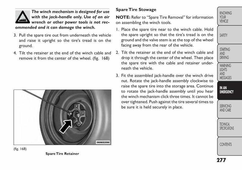
The winch mechanism is designed for usewith the jack-handle only. Use of an airwrench or other power tools is not rec-
ommended and it can damage the winch.
3. Pull the spare tire out from underneath the vehicleand raise it upright so the tire's tread is on theground.
4. Tilt the retainer at the end of the winch cable andremove it from the center of the wheel. (fig. 168)
SpareTire Stowage
NOTE: Refer to “Spare Tire Removal” for informationon assembling the winch tools.
1. Place the spare tire near to the winch cable. Holdthe spare upright so that the tire's tread is on theground and the valve stem is at the top of the wheelfacing away from the rear of the vehicle.
2. Tilt the retainer at the end of the winch cable anddrop it through the center of the wheel. Then placethe spare tire with the cable and retainer under-neath the vehicle.
3. Fit the assembled jack-handle over the winch drivenut. Rotate the jack-handle assembly clockwise toraise the spare tire into the storage area. Continueto rotate the jack-handle assembly until you hearthe winch mechanism click three times. It cannot beover tightened. Push against the tire several times tobe sure it is held securely in place.
(fig. 168)SpareTire Retainer
277
KNOWINGYOURVEHICLE
SAFETY
STARTINGANDDRIVING
WARNINGLIGHTSANDMESSAGES
IN ANEMERGENCY
SERVICINGAND CARE
TECHNICALSPECIFICATIONS
CONTENTS

JACKING INSTRUCTIONS
WARNING!Carefully follow these tire changingwarnings to help prevent personal injury
or damage to your vehicle:• Always park on a firm, level surface as far fromthe edge of the roadway as possible before rais-ing the vehicle.• Turn on the HazardWarning flashers.• Block the wheel diagonally opposite the wheelto be raised.• Set the parking brake firmly and set an auto-matic transmission in PARK; a manual transmis-sion in REVERSE.• Never start or run the engine with the vehicleon a jack.• Do not let anyone sit in the vehicle when it is ona jack.• Do not get under the vehicle when it is on ajack. If you need to get under a raised vehicle,take it to a service center where it can be raisedon a lift.• Only use the jack in the positions indicated andfor lifting this vehicle during a tire change.
(Continued)
(Continued)• If working on or near a roadway, be extremelycareful of motor traffic.• To assure that spare tires, flat or inflated, aresecurely stowed, spares must be stowed with thevalve stem facing the ground.
(fig. 169)
(fig. 169)Jack Warning Label
278
KNOWINGYOUR
VEHICLE
SAFETY
STARTINGAND
DRIVING
WARNINGLIGHTS
ANDMESSAGES
IN ANEMERGENCY
SERVICINGAND CARE
TECHNICALSPECIFICATIONS
CONTENTS

Do not attempt to raise the vehicle byjacking on locations other than thoseindicated in the Jacking Instructions for
this vehicle.(fig. 170)
1. Remove the spare tire, jack, and jack-handle fromstowage.
2. Loosen, but do not remove, the wheel nuts on thewheel with the flat tire. Turn the wheel nuts coun-terclockwise one turn while the wheel is still on theground.
3. Place the jack underneath the lift area that is closestto the flat tire. Center the jack saddle between thedrain flute formations on the sill flange. Turn the jackscrew clockwise to firmly engage the jack saddle withthe lift area of the sill flange. (fig. 171) (fig. 172)(fig. 173) (fig. 174)
4. Raise the vehicle by turning the jack screw clock-wise with the jack handle. Raise the vehicle until thetire just clears the road surface and enough clear-ance is obtained to install the spare tire. Minimumtire lift provides maximum stability.
(fig. 170)Jacking Locations
(fig. 171)Front Jacking Location
279
KNOWINGYOURVEHICLE
SAFETY
STARTINGANDDRIVING
WARNINGLIGHTSANDMESSAGES
IN ANEMERGENCY
SERVICINGAND CARE
TECHNICALSPECIFICATIONS
CONTENTS

WARNING!Raising the vehicle higher than neces-sary can make the vehicle less stable. It
could slip off the jack and hurt someone near it.Raise the vehicle only enough to remove the tire.
5. Remove the wheel nuts. For vehicles so equipped,remove the wheel cover from the wheel by hand.Do not pry the wheel cover off. Then pull the wheeloff the hub.
(fig. 172)Front Jack Engaged With Jack Handle
(fig. 173)Rear Jacking Location
(fig. 174)Rear Jack Engaged With Jack Handle
280
KNOWINGYOUR
VEHICLE
SAFETY
STARTINGAND
DRIVING
WARNINGLIGHTS
ANDMESSAGES
IN ANEMERGENCY
SERVICINGAND CARE
TECHNICALSPECIFICATIONS
CONTENTS

WARNING!To avoid possible personal injury,handlethe wheel covers with care to avoid con-
tact with any sharp edges.
6. Install the spare tire.
Be sure to mount the spare tire with thevalve stem facing outward. The vehiclecould be damaged if the spare tire is
mounted incorrectly.(fig. 175)
NOTE:
• For vehicles so equipped, do not attempt to install acenter cap or wheel cover on the compact spare.
• Refer to “Compact Spare Tire” and to “Limited-UseSpare” under “Tires — General Information” in“Technical Specifications” for additional warnings,cautions, and information about the spare tire, itsuse, and operation.
7. Install the wheel nuts with the cone-shaped end of thenut toward the wheel. Lightly tighten the wheel nuts.
WARNING!To avoid the risk of forcing the vehicle offthe jack, do not tighten the wheel nuts
fully until the vehicle has been lowered. Failure tofollow this warning may result in personal injury.
8. Lower the vehicle by turning the jack screw coun-terclockwise with the jack handle.
9. Finish tightening the lug nuts. Push down on thewrench while at the end of the handle for increasedleverage. Tighten the lug nuts in a star pattern untileach nut has been tightened twice. Refer to “TorqueSpecifications” in this section for proper lug nuttorque. If in doubt about the correct tightness, havethem checked with a torque wrench by your autho-rized dealer or service station.(fig. 175)
Mounting SpareTire
281
KNOWINGYOURVEHICLE
SAFETY
STARTINGANDDRIVING
WARNINGLIGHTSANDMESSAGES
IN ANEMERGENCY
SERVICINGAND CARE
TECHNICALSPECIFICATIONS
CONTENTS
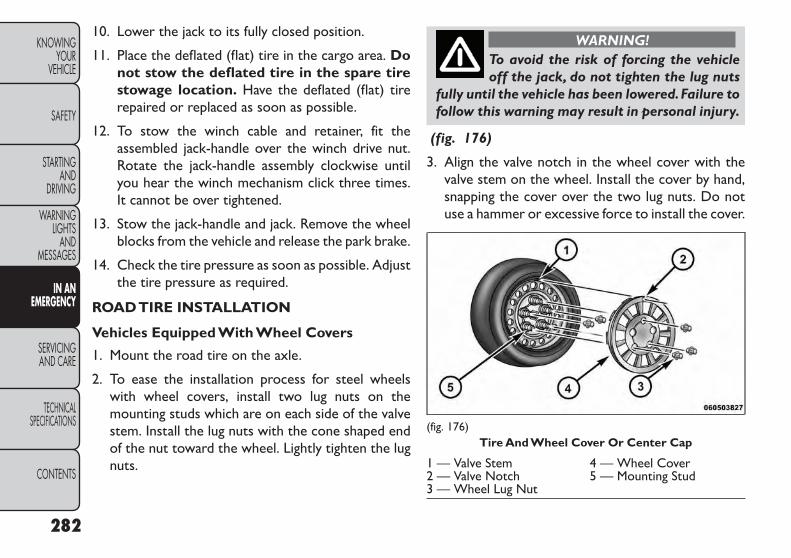
10. Lower the jack to its fully closed position.
11. Place the deflated (flat) tire in the cargo area. Donot stow the deflated tire in the spare tirestowage location. Have the deflated (flat) tirerepaired or replaced as soon as possible.
12. To stow the winch cable and retainer, fit theassembled jack-handle over the winch drive nut.Rotate the jack-handle assembly clockwise untilyou hear the winch mechanism click three times.It cannot be over tightened.
13. Stow the jack-handle and jack. Remove the wheelblocks from the vehicle and release the park brake.
14. Check the tire pressure as soon as possible. Adjustthe tire pressure as required.
ROADTIRE INSTALLATION
Vehicles Equipped With Wheel Covers
1. Mount the road tire on the axle.
2. To ease the installation process for steel wheelswith wheel covers, install two lug nuts on themounting studs which are on each side of the valvestem. Install the lug nuts with the cone shaped endof the nut toward the wheel. Lightly tighten the lugnuts.
WARNING!To avoid the risk of forcing the vehicleoff the jack, do not tighten the lug nuts
fully until the vehicle has been lowered.Failure tofollow this warning may result in personal injury.
(fig. 176)
3. Align the valve notch in the wheel cover with thevalve stem on the wheel. Install the cover by hand,snapping the cover over the two lug nuts. Do notuse a hammer or excessive force to install the cover.
(fig. 176)Tire And Wheel Cover Or Center Cap
1 — Valve Stem 4 — Wheel Cover2 — Valve Notch 5 — Mounting Stud3 — Wheel Lug Nut
282
KNOWINGYOUR
VEHICLE
SAFETY
STARTINGAND
DRIVING
WARNINGLIGHTS
ANDMESSAGES
IN ANEMERGENCY
SERVICINGAND CARE
TECHNICALSPECIFICATIONS
CONTENTS

4. Install the remaining lug nuts with the cone shapedend of the nut toward the wheel. Lightly tighten thelug nuts.
WARNING!To avoid the risk of forcing the vehicleoff the jack, do not tighten the lug nuts
fully until the vehicle has been lowered.Failure tofollow this warning may result in personal injury.
5. Lower the vehicle to the ground by turning the jackhandle counterclockwise.
6. Finish tightening the lug nuts. Push down on thewrench while at the end of the handle for increasedleverage. Tighten the lug nuts in a star pattern untileach nut has been tightened twice. For the correctlug nut torque refer to Torque Specifications in thissection. If in doubt about the correct tightness, havethem checked with a torque wrench by your autho-rized dealer or service station.
7. After 40 km check the lug nut torque with a torquewrench to ensure that all lug nuts are properlyseated against the wheel.
Vehicles Without Wheel Covers
1. Mount the road tire on the axle.
2. Install the remaining lug nuts with the cone shapedend of the nut toward the wheel. Lightly tighten thelug nuts.
WARNING!To avoid the risk of forcing the vehicleoff the jack, do not tighten the lug nuts
fully until the vehicle has been lowered.Failure tofollow this warning may result in personal injury.
3. Lower the vehicle to the ground by turning the jackhandle counterclockwise.
4. Finish tightening the lug nuts. Push down on thewrench while at the end of the handle for increasedleverage. Tighten the lug nuts in a star pattern untileach nut has been tightened twice. For proper lugnut torque refer to Torque Specifications in thissecton. If in doubt about the correct tightness, havethem checked with a torque wrench by your autho-rized dealer or service station.
5. After 40 km check the lug nut torque with a torquewrench to ensure that all lug nuts are properlyseated against the wheel.
283
KNOWINGYOURVEHICLE
SAFETY
STARTINGANDDRIVING
WARNINGLIGHTSANDMESSAGES
IN ANEMERGENCY
SERVICINGAND CARE
TECHNICALSPECIFICATIONS
CONTENTS
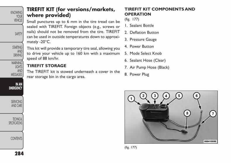
TIREFIT KIT (for versions/markets,where provided)Small punctures up to 6 mm in the tire tread can besealed with TIREFIT. Foreign objects (e.g., screws ornails) should not be removed from the tire. TIREFITcan be used in outside temperatures down to approxi-mately -20°C.
This kit will provide a temporary tire seal, allowing youto drive your vehicle up to 160 km with a maximumspeed of 88 km/hr.
TIREFIT STORAGEThe TIREFIT kit is stowed underneath a cover in therear storage bin in the cargo area.
TIREFIT KIT COMPONENTS ANDOPERATION(fig. 177)
1. Sealant Bottle
2. Deflation Button
3. Pressure Gauge
4. Power Button
5. Mode Select Knob
6. Sealant Hose (Clear)
7. Air Pump Hose (Black)
8. Power Plug
(fig. 177)
284
KNOWINGYOUR
VEHICLE
SAFETY
STARTINGAND
DRIVING
WARNINGLIGHTS
ANDMESSAGES
IN ANEMERGENCY
SERVICINGAND CARE
TECHNICALSPECIFICATIONS
CONTENTS

UsingThe Mode Select Knob And HosesYour TIREFIT kit is equipped with the following sym-bols to indicate the air or sealant mode.
• Selecting Air ModePush in the Mode Select Knob (5) and turn tothis position for air pump operation only. Usethe Black Air Pump Hose (7) when selectingthis mode.
• Selecting Sealant ModePush in the Mode Select Knob (5)and turn to this position to inject theTIREFIT Sealant and to inflate thetire. Use the Sealant Hose (clearhose) (6) when selecting this mode.
• UsingThe Power ButtonPush and release the Power Button (4) onceto turn On the TIREFIT kit. Push and releasethe Power Button (4) again to turn Off theTIREFIT kit.
• UsingThe Deflation ButtonPress the Deflation Button (2) to reduce theair pressure in the tire if it becomes over-inflated.
TIREFIT Usage Precautions
• Replace the TIREFIT Sealant Bottle (1) and SealantHose (6) prior to the expiration date (printed on thebottle label) to assure optimum operation of thesystem. Refer to “Sealing a Tire with TIREFIT” sec-tion (F) “Sealant Bottle and Hose Replacement”.
• The Sealant Bottle (1) and Sealant Hose (6) are a onetire application use. After each use, always replacethese components immediately at an authorizeddealer.
• When the TIREFIT sealant is in a liquid form, cleanwater, and a damp cloth will remove the materialfrom the vehicle or tire and wheel components.Once the sealant dries, it can easily be peeled off andproperly discarded.
• For optimum performance, make sure the valve stemon the wheel is free of debris before connecting theTIREFIT kit.
• You can use the TIREFIT air pump to inflate bicycletires. The kit also comes with two needles, located inthe Accessory Storage Compartment (on the bot-tom of the air pump) for inflating sport balls, rafts, orsimilar inflatable items. However, use only the AirPump Hose (7) and make sure the Mode Select Knob(5) is in the Air Mode when inflating such items to
285
KNOWINGYOURVEHICLE
SAFETY
STARTINGANDDRIVING
WARNINGLIGHTSANDMESSAGES
IN ANEMERGENCY
SERVICINGAND CARE
TECHNICALSPECIFICATIONS
CONTENTS

avoid injecting sealant into them. The TIREFIT Seal-ant is only intended to seal punctures less than 6 mmdiameter in the tread of your vehicle.
• Do not lift or carry the TIREFIT kit by the hoses.
WARNING!• Do not attempt to seal a tire on theside of the vehicle close to traffic. Pull
far enough off the road to avoid the danger ofbeing hit when using theTIREFIT kit.• Do not use TIREFIT or drive the vehicle underthe following circumstances:– If the puncture in the tire tread is approxi-mately 6 mm or larger.– If the tire has any sidewall damage.– If the tire has any damage from driving withextremely low tire pressure.– If the tire has any damage from driving on aflat tire.– If the wheel has any damage.– If you are unsure of the condition of the tire orthe wheel.• Keep TIREFIT away from open flame or heatsource.
(Continued)
(Continued)• A loose TIREFIT kit thrown forward in a colli-sion or hard stop could endanger the occupantsof the vehicle.Always stow theTIREFIT kit in theplace provided. Failure to follow these warningscan result in injuries that are serious or fatal toyou, your passengers, and others around you.• Take care not to allow the contents ofTIREFITto come in contact with hair, eyes, or clothing.TIREFIT is harmful if inhaled, swallowed, or ab-sorbed through the skin: It causes skin, eye, andrespiratory irritation. Flush immediately withplenty of water if there is any contact with eyesor skin. Change clothing as soon as possible, ifthere is any contact with clothing.• TIREFIT Sealant solution contains latex.In caseof allergic reaction or rash, consult a physicianimmediately. Keep TIREFIT out of reach of chil-dren. If swallowed,rinse mouth immediately withplenty of water and drink plenty of water.Do notinduce vomiting! Consult a physician immedi-ately.• Use the gloves provided in the Accessory Stor-age Compartment (located on the bottom of theair pump) when operating theTIREFIT kit.
286
KNOWINGYOUR
VEHICLE
SAFETY
STARTINGAND
DRIVING
WARNINGLIGHTS
ANDMESSAGES
IN ANEMERGENCY
SERVICINGAND CARE
TECHNICALSPECIFICATIONS
CONTENTS
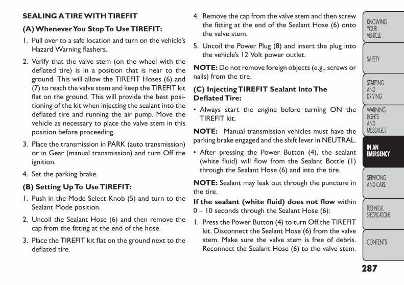
SEALING ATIRE WITHTIREFIT
(A) WheneverYou StopTo UseTIREFIT:
1. Pull over to a safe location and turn on the vehicle’sHazard Warning flashers.
2. Verify that the valve stem (on the wheel with thedeflated tire) is in a position that is near to theground. This will allow the TIREFIT Hoses (6) and(7) to reach the valve stem and keep the TIREFIT kitflat on the ground. This will provide the best posi-tioning of the kit when injecting the sealant into thedeflated tire and running the air pump. Move thevehicle as necessary to place the valve stem in thisposition before proceeding.
3. Place the transmission in PARK (auto transmission)or in Gear (manual transmission) and turn Off theignition.
4. Set the parking brake.
(B) Setting UpTo UseTIREFIT:
1. Push in the Mode Select Knob (5) and turn to theSealant Mode position.
2. Uncoil the Sealant Hose (6) and then remove thecap from the fitting at the end of the hose.
3. Place the TIREFIT kit flat on the ground next to thedeflated tire.
4. Remove the cap from the valve stem and then screwthe fitting at the end of the Sealant Hose (6) ontothe valve stem.
5. Uncoil the Power Plug (8) and insert the plug intothe vehicle’s 12 Volt power outlet.
NOTE: Do not remove foreign objects (e.g., screws ornails) from the tire.
(C) InjectingTIREFIT Sealant IntoTheDeflatedTire:
• Always start the engine before turning ON theTIREFIT kit.
NOTE: Manual transmission vehicles must have theparking brake engaged and the shift lever in NEUTRAL.
• After pressing the Power Button (4), the sealant(white fluid) will flow from the Sealant Bottle (1)through the Sealant Hose (6) and into the tire.
NOTE: Sealant may leak out through the puncture inthe tire.If the sealant (white fluid) does not flow within0 – 10 seconds through the Sealant Hose (6):
1. Press the Power Button (4) to turn Off the TIREFITkit. Disconnect the Sealant Hose (6) from the valvestem. Make sure the valve stem is free of debris.Reconnect the Sealant Hose (6) to the valve stem.
287
KNOWINGYOURVEHICLE
SAFETY
STARTINGANDDRIVING
WARNINGLIGHTSANDMESSAGES
IN ANEMERGENCY
SERVICINGAND CARE
TECHNICALSPECIFICATIONS
CONTENTS

Check that the Mode Select Knob (5) is in theSealant Mode position and not Air Mode. Press thePower Button (4) to turn On the TIREFIT kit.
2. Connect the Power Plug (8) to a different 12 Voltpower outlet in your vehicle or another vehicle, ifavailable. Make sure the engine is running beforeturning ON the TIREFIT kit.
3. The Sealant Bottle (1) may be empty due to previ-ous use. Call for assistance.
NOTE: If the Mode Select Knob (5) is on Air Modeand the pump is operating, air will dispense from theAir Pump Hose (7) only, not the Sealant Hose (6).
If the sealant (white fluid) does flow through theSealant Hose (6):
1. Continue to operate the pump until sealant is nolonger flowing through hose (typically takes 30 -70 seconds). As the sealant flows through the Seal-ant Hose (6), the Pressure Gauge (3) can read ashigh as 5 Bar. The Pressure Gauge (3) will decreasequickly from approximately 5 Bar to the actual tirepressure when the Sealant Bottle (1) is empty.
2. The pump will start to inject air into the tireimmediately after the Sealant Bottle (1) is empty.Continue to operate the pump and inflate the tire
to the pressure indicated on the tire pressure labelon the driver-side latch pillar (recommended pres-sure). Check the tire pressure by looking at thePressure Gauge (3).
If the tire does not inflate to at least 1.8 Barpressure within 15 minutes:
• The tire is too badly damaged. Do not attempt todrive the vehicle further. Call for assistance.
NOTE: If the tire becomes over-inflated, press theDeflation Button to reduce the tire pressure to therecommended inflation pressure before continuing.
If the tire inflates to the recommended pressureor is at least 1.8 Bar pressure within 15 minutes:
1. Press the Power Button (4) to turn off the TIREFITkit.
2. Remove the Speed Limit sticker from the top of theSealant Bottle (1) and place the sticker on theinstrument panel.
3. Immediately disconnect the Sealant Hose (6) fromthe valve stem, reinstall the cap on the fitting at theend of the hose, and place the TIREFIT kit in thevehicle storage location. Quickly proceed to (D)“Drive Vehicle”.
288
KNOWINGYOUR
VEHICLE
SAFETY
STARTINGAND
DRIVING
WARNINGLIGHTS
ANDMESSAGES
IN ANEMERGENCY
SERVICINGAND CARE
TECHNICALSPECIFICATIONS
CONTENTS

• The metal end fitting from Power Plug(8) may get hot after use, so it should behandled carefully.
• Failure to reinstall the cap on the fitting at theend of the Sealant Hose (6) can result in sealantcontacting your skin, clothing, and the vehicle’sinterior. It can also result in sealant contactinginternalTIREFIT kit components which may causepermanent damage to the kit.
(D) DriveVehicle:Immediately after injecting sealant and inflating the tire,drive the vehicle 8 km or 10 minutes to ensure distri-bution of the TIREFIT Sealant within the tire. Do notexceed 88 km/h.
WARNING!TIREFIT is not a permanent flat tirerepair. Have the tire inspected and re-
paired or replaced after using TIREFIT. Do notexceed 88 km/h until the tire is repaired orreplaced.Failure to follow this warning can resultin injuries that are serious or fatal to you, yourpassengers, and others around you.
(E) After Driving:Pull over to a safe location. Refer to “Whenever YouStop to Use TIREFIT” before continuing.
1. Turn the Mode Select Knob (5) to the Air Modeposition.
2. Uncoil the power plug and insert the plug into thevehicle's 12 Volt power outlet.
3. Uncoil the Air Pump Hose (7) (black in color) andscrew the fitting at the end of hose (7) onto thevalve stem.
4. Check the pressure in the tire by reading the Pres-sure Gauge (3).
If tire pressure is less than 1.3 Bar, the tire is toobadly damaged. Do not attempt to drive the vehiclefurther. Call for assistance.
If the tire pressure is 1.3 bar or higher:
1. Press the Power Button (4) to turn on TIREFIT andinflate the tire to the pressure indicated on the tireand loading information label on the driver-sidedoor opening.
NOTE: If the tire becomes over-inflated, press theDeflation Button to reduce the tire pressure to therecommended inflation pressure before continuing.
289
KNOWINGYOURVEHICLE
SAFETY
STARTINGANDDRIVING
WARNINGLIGHTSANDMESSAGES
IN ANEMERGENCY
SERVICINGAND CARE
TECHNICALSPECIFICATIONS
CONTENTS

2. Disconnect the TIREFIT kit from the valve stem,reinstall the cap on the valve stem and unplug from12 Volt outlet.
3. Place the TIREFIT kit in its proper storage area inthe vehicle.
4. Have the tire inspected and repaired or replaced atthe earliest opportunity at an authorized dealer ortire service center.
5. Replace the Sealant Bottle (1) and Sealant Hose (6)assembly at your authorized dealer as soon as pos-sible. Refer to “(F) Sealant Bottle and Hose Replace-ment.”
NOTE: When having the tire serviced, advise theauthorized dealer or service center that the tire hasbeen sealed using the TIREFIT service kit.
(F) Sealant Bottle And Hose Replacement:
1. Uncoil the Sealant Hose (6) (clear in color).
2. Locate the round Sealant Bottle release button inthe recessed area under the sealant bottle.
3. Press the Sealant Bottle release button. The SealantBottle (1) will pop up. Remove the bottle anddispose of it accordingly.
4. Clean any remaining sealant from the TIREFIT hous-ing.
5. Position the new Sealant Bottle (1) in the housing sothat the Sealant Hose (6) aligns with the hose slot inthe front of the housing. Press the bottle into thehousing. An audible click will be heard indicating thebottle is locked into place.
6. Verify that the cap is installed on the fitting at theend of the Sealant Hose (6) and return the hose toits storage area (located on the bottom of the airpump).
7. Return the TIREFIT kit to its storage location in thevehicle.
290
KNOWINGYOUR
VEHICLE
SAFETY
STARTINGAND
DRIVING
WARNINGLIGHTS
ANDMESSAGES
IN ANEMERGENCY
SERVICINGAND CARE
TECHNICALSPECIFICATIONS
CONTENTS

REPLACEMENT BULBSAll the inside bulbs are brass or glass wedge base.Aluminum base bulbs are not approved and should notbe used for replacement.
LIGHT BULBS – Interior Bulb NumberCourtesy/Reading Lamps (Incandescent) . . . . . . . 578Courtesy/Reading Lamps(Optional LED) . . . . . . . . . . . . . . . LED (Serviced at
Authorized Dealer)Glove Box Lamp . . . . . . . . . . . . . . . . . . . . . . . . 194Cargo Lamp . . . . . . . . . . . . . . . . . . . . . . . . . . . 579Optional Door MapPocket/Cupholder . . . . . . . . . . . . . LED (Serviced at
Authorized Dealer)
NOTE: For lighted switches, see your authorizeddealer for replacement instructions.
LIGHTS BULBS – Outside Bulb NumberLow Beam Headlamp . . . . . . . . . . . . . . . . . . . . H11High Beam Headlamp . . . . . . . . . . . . . . . . HB3/9005Front Turn Signal . . . . . . . . . . . . . . PY27W/3757AKFront Position Lamp . . . . . . . . . . . . . . . . . . . W5WFront Fog Lamp . . . . . . . . . . . . . . . . . . . . . PSX24WRear Fog Lamp . . . . . . . . . . . . . . . . . . . . . . . PS19WSide Repeater Lamp . . . . . . . . . . . . . . . . . . . WY5WCenter High Mounted StopLamp (CHMSL) . . . . . . . . . . . . . . . LED (Serviced at
Authorized Dealer)Rear Tail/Stop . . . . . . . . . . . . . . . . LED (Serviced at
Authorized Dealer)Rear Tail Liftgate . . . . . . . . . . . . . . LED (Serviced at
Authorized Dealer)Rear Turn Signal . . . . . . . . . . . . . . . . . . . . . WY21WBackup Lamp . . . . . . . . . . . . . . . . . . . . . . . . W21WLicense Lamp . . . . . . . . . . . . . . . . . . . . . . . . . W5W
291
KNOWINGYOURVEHICLE
SAFETY
STARTINGANDDRIVING
WARNINGLIGHTSANDMESSAGES
IN ANEMERGENCY
SERVICINGAND CARE
TECHNICALSPECIFICATIONS
CONTENTS

BULB REPLACEMENTNOTE: Lens fogging can occur under certain atmo-spheric conditions. This will usually clear as atmo-spheric conditions change to allow the condensation tochange back into a vapor. Turning the lamps on willusually accelerate the clearing process.
Where possible, it is advisable to havebulbs changed at a FIAT Dealership.Proper operation and orientation of the
external lights are essential for driving safety andcomplying with the law.
LOW BEAM/HIGH BEAM/FRONTTURNSIGNAL AND FRONT POSITION LAMP
1. Open the hood.
NOTE: It may be necessary to remove the air cleanerfilter housing and position the Totally Integrated PowerModule (TIPM) aside to replace certain lamps in the leftheadlamp housing.
2. Rotate the applicable bulb and connector assembly¼ turn counterclockwise and remove the assemblyfrom the headlamp housing. (fig. 178)
3. Disconnect the bulb from the harness connectorand then connect the replacement bulb.
Do not touch the new bulb with yourfingers. Oil contamination will severelyshorten bulb life. If the bulb comes in
contact with any oily surface, clean the bulb withrubbing alcohol.
4. Install the bulb and connector assembly into theheadlamp housing and rotate it ¼ turn clockwise tolock it in place.
(fig. 178)
1 — Front Turn Signal Lamp Bulb2 — Low Beam Headlamp Bulb3 — Front Position Bulb4 — High Beam Headlamp Bulb
292
KNOWINGYOUR
VEHICLE
SAFETY
STARTINGAND
DRIVING
WARNINGLIGHTS
ANDMESSAGES
IN ANEMERGENCY
SERVICINGAND CARE
TECHNICALSPECIFICATIONS
CONTENTS

FRONT FOG LAMP
NOTE: Turn the steering wheel to the right if replac-ing the left front fog lamp or to the left if replacing theright front fog lamp to allow for easier access to thefront of the wheel well.
1. Remove the fasteners retaining the front lower wheelwell access panel and remove the access panel.
2. Remove the electrical connector from the fog lamphousing. (fig. 179)
3. Firmly grasp the bulb by the two side latches andsqueeze them together to unlock the bulb from theback of the front fog lamp housing.
4. Pull the bulb straight out from the keyed opening inthe housing.
5. Align the index tabs of the replacement front foglamp bulb with the slots in the collar of the bulbopening on the back of the front fog lamp housing.
Do not touch the new bulb with yourfingers. Oil contamination will severelyshorten bulb life. If the bulb comes in
contact with an oily surface, clean the bulb withrubbing alcohol.
6. Insert bulb into the lamp housing until the indextabs are engaged in the slots of the collar.
7. Firmly and evenly push the bulb straight into thelamp housing until both side latches lock firmly intoplace.
(fig. 179)Front Fog Lamp Electrical Connector
293
KNOWINGYOURVEHICLE
SAFETY
STARTINGANDDRIVING
WARNINGLIGHTSANDMESSAGES
IN ANEMERGENCY
SERVICINGAND CARE
TECHNICALSPECIFICATIONS
CONTENTS

REAR FOG LAMP
1. Reach behind the bumper above the bumper rein-forcement and press the release tabs on the fog lamphousing. (fig. 180)
2. Separate the fog lamp housing from the bumperfascia.
3. Disconnect the electrical harness connector.(fig. 181)
4. Firmly grasp the bulb by the two side latches andsqueeze them together to unlock the bulb from theback of the lamp housing.
5. Pull the bulb straight out from the keyed opening inthe housing.
6. Remove the bulb from the connector socket andinstall the replacement bulb.
7. Align the index tabs of the replacement rear foglamp bulb/socket assembly with the slots in thecollar of the bulb opening on the back of the lamphousing.
8. Insert bulb into the lamp housing until the indextabs are engaged in the slots of the collar.
9. Firmly and evenly push the bulb straight into thelamp housing until both side latches lock firmly intoplace.
10. Reinstall the fog lamp housing.
(fig. 180)ReleaseTabs
(fig. 181)Electrical Connector
294
KNOWINGYOUR
VEHICLE
SAFETY
STARTINGAND
DRIVING
WARNINGLIGHTS
ANDMESSAGES
IN ANEMERGENCY
SERVICINGAND CARE
TECHNICALSPECIFICATIONS
CONTENTS

SIDE REPEATER LAMPThe side repeater lamps are located in both frontfender panels.
1. Push the side repeater lens to left side to release thespring tension and then pull it outward.
2. Disconnect the bulb from the harness connectorand then connect the replacement bulb. (fig. 182)
3. Engage the right hook of the side repeater lamp intothe sheet metal (note correct orientation of letter-ing on lens).
4. Rotate the side repeater lamp in place until the leftside engages (you will hear a light click).
REARTURN SIGNAL AND BACKUP LAMPThe taillamps are a two-piece design. The tail/stop/rearturn signal lamps are located in the rear corner bodypanels. The tail and backup lamps are located in theliftgate.
ChangingThe RearTurn Signal Lamp
1. Open the liftgate.
2. Remove the two fasteners from the inboard side ofthe taillamp housing. (fig. 183)
(fig. 182)Side Repeater Bulb Removal
(fig. 183)InboardTail Lamp Housing Fasteners
295
KNOWINGYOURVEHICLE
SAFETY
STARTINGANDDRIVING
WARNINGLIGHTSANDMESSAGES
IN ANEMERGENCY
SERVICINGAND CARE
TECHNICALSPECIFICATIONS
CONTENTS

3. Carefully insert a trim stick (plastic flat-blade tool)between the body panel and the outboard side ofthe taillamp housing with one hand and grasp theflange on the inboard side of the taillamp housingwith the other hand. Use the trim stick and handpressure together to disengage the taillamp housingfrom the vehicle.
4. Rotate the applicable bulb's electrical connector¼ turn counterclockwise and remove it from thetaillamp housing.
5. Remove the bulb from the connector socket andinstall the replacement bulb.
6. Install the bulb and connector assembly into thetaillamp housing and rotate the connector ¼ turnclockwise to lock it in place.
7. Reinstall the taillamp housing and fasteners.
ChangingThe Backup Lamp
1. Open the liftgate.
2. Remove the two fasteners retaining the taillamphousing to the liftgate from the inboard face of theliftgate. (fig. 184)
3. Carefully insert a trim stick (plastic flat-blade tool)between the taillamp housing and the liftgate. Use thetrim stick and hand pressure together to disengagethe taillamp housing from the liftgate. (fig. 185)
(fig. 184)Tail Lamp Housing Retainers
(fig. 185)Tail Gate Lamp
296
KNOWINGYOUR
VEHICLE
SAFETY
STARTINGAND
DRIVING
WARNINGLIGHTS
ANDMESSAGES
IN ANEMERGENCY
SERVICINGAND CARE
TECHNICALSPECIFICATIONS
CONTENTS

4. Rotate the applicable bulb's electrical connector¼ turn counterclockwise and remove it from thehousing.
5. Remove the bulb from the connector socket andinstall the replacement bulb.
6. Install the bulb and connector assembly into thehousing and rotate the connector ¼ turn clockwiseto lock it in place.
7. Reinstall the taillamp housing and fasteners.
LICENSE PLATE LAMP
1. Push the small locking tab sticking out of the end ofthe lens toward the side of the vehicle and hold it inthat position.
2. Insert a small flat-blade tool between the end of thelens with the locking tab and the surrounding hous-ing and then pivot the tool to separate the lens fromthe housing.
3. Hold the lens with one hand and rotate the bulb'selectrical connector ¼ turn counterclockwise withthe other hand and then separate the bulb andconnector assembly from the lens.
4. Remove the bulb from the connector socket andinstall the replacement bulb.
5. Install the bulb and connector assembly into thelens and rotate the connector ¼ turn clockwise tolock it in place.
6. Insert the end of the lens without the locking tabinto the housing on the liftgate and then push theopposite end of the lens into the housing, makingsure it locks in the housing.
297
KNOWINGYOURVEHICLE
SAFETY
STARTINGANDDRIVING
WARNINGLIGHTSANDMESSAGES
IN ANEMERGENCY
SERVICINGAND CARE
TECHNICALSPECIFICATIONS
CONTENTS

FUSES
WARNING!• When replacing a blown fuse, alwaysuse an appropriate replacement fuse
with the same amp rating as the original fuse.Never replace a fuse with another fuse of higheramp rating. Never replace a blown fuse withmetal wires or any other material. Failure to useproper fuses may result in serious personal in-jury, fire and/or property damage.• Before replacing a fuse, make sure that theignition is off and that all the other services areswitched off and/or disengaged.• If the replaced fuse blows again, contact anauthorized dealer.• If a general protection fuse for safety systems(air bag system, braking system), power unit sys-tems (engine system,gearbox system) or steeringsystem blows, contact an authorized dealer.
INTERIOR FUSESThe interior fuse panel is located on the passenger sideunder the instrument panel.
CavityCar-
tridgeFuse
Mini-Fuse
Description
F10030 Amp
Pink
110V AC Inverter –For Versions/
Markets, WhereProvided
F10110 Amp
RedInterior Lights
F10220 AmpYellow
Cigar Lighter inInstrument Panel/Left Rear Power
Outlet
F10320 AmpYellow
Power Outlet inConsole Bin/PowerOutlet in Rear of
Console
F10520 AmpYellow
Heated Seats – ForVersions/Markets,Where Provided
F10620 AmpYellow
Rear Power Outlet
298
KNOWINGYOUR
VEHICLE
SAFETY
STARTINGAND
DRIVING
WARNINGLIGHTS
ANDMESSAGES
IN ANEMERGENCY
SERVICINGAND CARE
TECHNICALSPECIFICATIONS
CONTENTS

CavityCar-
tridgeFuse
Mini-Fuse
Description
F10710 Amp
Red
Rear Camera – ForVersions/Markets,Where Provided
F10815 Amp
BlueInstrument Panel
F10910 Amp
RedClimate Control/
HVAC
F11010 Amp
RedOccupant Restraint
Controller
F11210 Amp
RedSpare
F11420 AmpYellow
Rear HVAC Blower/Motor
F11520 AmpYellow
Rear Wiper Motor
F11630 Amp
PinkRear Defroster
(EBL)
F11710 Amp
RedHeated Mirrors
F11810 Amp
RedOccupant Restraint
Controller
F11910 Amp
RedSteering ColumnControl Module
CavityCar-
tridgeFuse
Mini-Fuse
Description
F12010 Amp
Red
All Wheel Drive –For Versions/
Markets, WhereProvided
F12115 Amp
BlueWireless Ignition
Node
F12225 AmpNatural
Driver Door Module
F12325 AmpNatural
Passenger DoorModule
F12410 Amp
RedMirrors
F12510 Amp
RedSteering ColumnControl Module
F12610 Amp
RedAudio Amplifier
F12720 AmpYellow
Trailer Tow – ForVersions/Markets,Where Provided
F12815 Amp
BlueRadio
F12915 Amp
Blue
Video/DVD – ForVersions/Markets,Where Provided
299
KNOWINGYOURVEHICLE
SAFETY
STARTINGANDDRIVING
WARNINGLIGHTSANDMESSAGES
IN ANEMERGENCY
SERVICINGAND CARE
TECHNICALSPECIFICATIONS
CONTENTS

CavityCar-
tridgeFuse
Mini-Fuse
Description
F13015 Amp
BlueClimate Control/Instrument Panel
F13110 Amp
Red
PassengerAssistance/HandsFree System – ForVersions/Markets,Where Provided
F13210 Amp
RedTire Pressure
Module
F13310 Amp
RedSpare
UNDERHOOD FUSES (POWERDISTRIBUTION CENTER)The power distribution center is located in the enginecompartment. (fig. 186)
(fig. 186)Power Distribution Center (Fuses)
300
KNOWINGYOUR
VEHICLE
SAFETY
STARTINGAND
DRIVING
WARNINGLIGHTS
ANDMESSAGES
IN ANEMERGENCY
SERVICINGAND CARE
TECHNICALSPECIFICATIONS
CONTENTS

CavityCar-
tridgeFuse
Mini-Fuse
Description
F10160 AmpYellow
Interior Power Dis-tribution Center Rail
F10260 AmpYellow
Interior Power Dis-tribution Center Rail
F10360 AmpYellow
Interior Power Dis-tribution Center Rail
F10560 AmpYellow
Interior Power Dis-tribution Center Rail
Ignition Run Relay
F10660 AmpYellow
Interior Power Dis-tribution Center Rail
Run/AccessoryRelays
F13940 AmpGreen
Climate ControlSystem Blower
F14030 Amp
PinkPower Locks
F14140 AmpGreen
Anti-Lock BrakeSystem
F14240 AmpGreen
Glow Plugs – ForVersions/Markets,Where Provided
F14340 AmpGreen
Exterior Lights 1
CavityCar-
tridgeFuse
Mini-Fuse
Description
F14440 AmpGreen
Exterior Lights 2
F14530 Amp
PinkTo Body
Computer – Lamp
F14630 Amp
PinkSpare
F14730 Amp
PinkSpare
F14840 AmpGreen
Radiator Fan Motor
F14930 Amp
PinkStarter Solenoid
F15025 AmpNatural
Powertrain ControlModules
F15130 Amp
Pink
Headlamp WasherMotor – For
Versions/Markets,Where Provided
F15225 AmpNatural
Diesel Fuel Heater –For Versions/
Markets, WhereProvided
F15320 AmpYellow
Fuel Pump
301
KNOWINGYOURVEHICLE
SAFETY
STARTINGANDDRIVING
WARNINGLIGHTSANDMESSAGES
IN ANEMERGENCY
SERVICINGAND CARE
TECHNICALSPECIFICATIONS
CONTENTS

CavityCar-
tridgeFuse
Mini-Fuse
Description
F15610 Amp
Red
Brake/ElectronicStability Control
Module
F15710 Amp
Red
Transfer Case Mod-ule – For Versions/Markets, Where
Provided
F15810 Amp
Red
Active Hood Module– For Versions/Markets, Where
Provided
F15910 Amp
RedSpare
F16020 AmpYellow
Interior Lights
F16120 AmpYellow
Horn
F16250 Amp
Red
Cabin Heater #1/Vacuum Pump – ForVersions/Markets,Where Provided
F16350 Amp
Red
Cabin Heater #2 –For Versions/
Markets, WhereProvided
CavityCar-
tridgeFuse
Mini-Fuse
Description
F16425 AmpNatural
Powertrain AutoShutdown
F16520 AmpYellow
PowertrainShutdown
F16620 AmpYellow
Spare
F16730 AmpGreen
PowertrainShutdown
F16810 Amp
RedAir Conditioner
Clutch
F16940 AmpGreen
Emissions – PartialZero EmissionsVehicle Motor
F17015 Amp
Blue
Emissions – PartialZero Emissions
Vehicle Actuators
F17220 AmpYellow
Spare
F17325 AmpNatural
Anti Lock BrakeValves
F17420 AmpYellow
Siren – For Versions/Markets, Where
Provided
F17530 AmpGreen
Spare
302
KNOWINGYOUR
VEHICLE
SAFETY
STARTINGAND
DRIVING
WARNINGLIGHTS
ANDMESSAGES
IN ANEMERGENCY
SERVICINGAND CARE
TECHNICALSPECIFICATIONS
CONTENTS
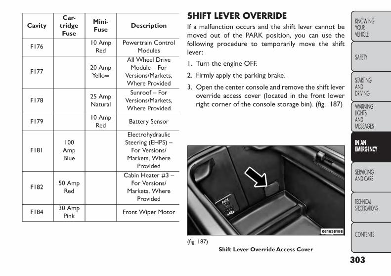
CavityCar-
tridgeFuse
Mini-Fuse
Description
F17610 Amp
RedPowertrain Control
Modules
F17720 AmpYellow
All Wheel DriveModule – For
Versions/Markets,Where Provided
F17825 AmpNatural
Sunroof – ForVersions/Markets,Where Provided
F17910 Amp
RedBattery Sensor
F181100AmpBlue
ElectrohydraulicSteering (EHPS) –
For Versions/Markets, Where
Provided
F18250 Amp
Red
Cabin Heater #3 –For Versions/
Markets, WhereProvided
F18430 Amp
PinkFront Wiper Motor
SHIFT LEVER OVERRIDEIf a malfunction occurs and the shift lever cannot bemoved out of the PARK position, you can use thefollowing procedure to temporarily move the shiftlever:
1. Turn the engine OFF.
2. Firmly apply the parking brake.
3. Open the center console and remove the shift leveroverride access cover (located in the front lowerright corner of the console storage bin). (fig. 187)
(fig. 187)Shift Lever Override Access Cover
303
KNOWINGYOURVEHICLE
SAFETY
STARTINGANDDRIVING
WARNINGLIGHTSANDMESSAGES
IN ANEMERGENCY
SERVICINGAND CARE
TECHNICALSPECIFICATIONS
CONTENTS

4. Press and maintain firm pressure on the brake pedal.
5. Insert a screwdriver or similar small tool into theaccess port, and push and hold the override releaselever forward.
6. Move the shift lever to the NEUTRAL position.
7. The vehicle may then be started in NEUTRAL.
8. Reinstall the shift lever override access cover.
FREEING A STUCK VEHICLEIf your vehicle becomes stuck in mud, sand, or snow, itcan often be moved using a rocking motion. Turn thesteering wheel right and left to clear the area aroundthe front wheels. Then shift back and forth betweenDRIVE and REVERSE (with automatic transmission) or2nd gear and REVERSE (with manual transmission),while gently pressing the accelerator. Use the leastamount of accelerator pedal pressure that will maintainthe rocking motion, without spinning the wheels orracing the engine.
NOTE: Press the "ESC Off" switch, to place theElectronic Stability Control (ESC) system in"Partial Off" mode, before rocking the ve-hicle. Refer to “Electronic Brake Control” in“Knowing Your Vehicle” for further informa-
tion. Once the vehicle has been freed, press the "ESCOff" switch again to restore "ESC On" mode.
304
KNOWINGYOUR
VEHICLE
SAFETY
STARTINGAND
DRIVING
WARNINGLIGHTS
ANDMESSAGES
IN ANEMERGENCY
SERVICINGAND CARE
TECHNICALSPECIFICATIONS
CONTENTS

• Racing the engine or spinning thewheels may lead to transmission over-heating and failure. Allow the engine to
idle with the shift lever in NEUTRAL for at leastone minute after every five rocking-motioncycles.This will minimize overheating and reducethe risk of transmission failure during prolongedefforts to free a stuck vehicle.• When “rocking” a stuck vehicle by shifting be-tween DRIVE/2nd gear and REVERSE,do not spinthe wheels faster than 24 km/h, or drivetraindamage may result.• Revving the engine or spinning the wheels toofast may lead to transmission overheating andfailure. It can also damage the tires. Do not spinthe wheels above 48 km/h while in gear (no trans-mission shifting occurring).
WARNING!Fast spinning tires can be dangerous.Forces generated by excessive wheel
speeds may cause damage,or even failure,of theaxle and tires. A tire could explode and injuresomeone.Do not spin your vehicle's wheels fasterthan 48 km/h or for longer than 30 secondscontinuously without stopping when you arestuck and do not let anyone near a spinningwheel, no matter what the speed.
305
KNOWINGYOURVEHICLE
SAFETY
STARTINGANDDRIVING
WARNINGLIGHTSANDMESSAGES
IN ANEMERGENCY
SERVICINGAND CARE
TECHNICALSPECIFICATIONS
CONTENTS

TOW EYEYour vehicle is equipped with a tow eye that can beused to tow a disabled vehicle. (fig. 188)
Tow eyes are for emergency use only, torescue a vehicle stranded off road.Do notuse tow eyes for tow truck hookup or
highway towing.You could damage your vehicle.Tow straps are recommended when towing thevehicle; chains may cause vehicle damage.
WARNING!Stand clear of vehicles when pulling withtow eyes. Tow straps and chains may
break, causing serious injury.
(fig. 188)Tow Eye
306
KNOWINGYOUR
VEHICLE
SAFETY
STARTINGAND
DRIVING
WARNINGLIGHTS
ANDMESSAGES
IN ANEMERGENCY
SERVICINGAND CARE
TECHNICALSPECIFICATIONS
CONTENTS

FRONTTOW EYE USAGEThe front tow eye receptacle is located on the lowerright side of the front fascia.
To install the tow eye, remove the rubber plug andthread the tow eye into the receptacle.
Insert the flat end of the jack handle through the eyeand tighten, refer to “Jacking and Tire Changing” forfurther information. The tow hook must be fully seatedto the attaching bracket through the lower front fasciaas shown. If the tow hook is not fully seated to theattaching bracket, the vehicle should not be towed.(fig. 189)
REARTOW EYE USAGEThe rear tow eye receptacle is located behind a door,located on the left rear bumper fascia.
To install the tow eye, open the door using the vehiclekey or a small screwdriver, and thread the tow eye intothe receptacle.
Insert the flat end of the jack handle through the eyeand tighten, refer to “Jacking and Tire Changing” forfurther information. The tow hook must be fully seatedto the attaching bracket through the lower rear fasciaas shown. If the tow hook is not fully seated to theattaching bracket, the vehicle should not be towed.(fig. 190)
(fig. 189)FrontTow Eye Installed
(fig. 190)RearTow Eye Installed
307
KNOWINGYOURVEHICLE
SAFETY
STARTINGANDDRIVING
WARNINGLIGHTSANDMESSAGES
IN ANEMERGENCY
SERVICINGAND CARE
TECHNICALSPECIFICATIONS
CONTENTS

TOWING A DISABLED VEHICLEThis section describes procedures for towing a disabled vehicle using a commercial towing service.
Towing ConditionWheels OFFthe Ground
FWD MODELSMANUAL
TRANSMISSION
FWD MODELSAUTOMATIC
TRANSMISSIONAWD MODELS
Flat Tow NONE
• Transmission inNEUTRAL
• Ignition in ACC orON/RUN position
If tranmission isoperable:
• Transmission inNEUTRAL
• Ignition in ACC orON/RUN position
• 40 km/h max speed
• 24 kilometers maxdistance
NOT ALLOWED
Wheel Lift orDolly Tow
Rear NOT ALLOWED NOT ALLOWED
Front OK OK NOT ALLOWEDFlatbed ALL BEST METHOD BEST METHOD OK
308
KNOWINGYOUR
VEHICLE
SAFETY
STARTINGAND
DRIVING
WARNINGLIGHTS
ANDMESSAGES
IN ANEMERGENCY
SERVICINGAND CARE
TECHNICALSPECIFICATIONS
CONTENTS

Proper towing or lifting equipment is required to pre-vent damage to your vehicle. Use only tow bars andother equipment designed for this purpose, followingequipment manufacturer’s instructions. Use of safetychains is mandatory. Attach a tow bar or other towingdevice to main structural members of the vehicle, notto bumpers or associated brackets. State and local lawsregarding vehicles under tow must be observed.
If you must use the accessories (wipers, defrosters,etc.) while being towed, the ignition must be in theON/RUN position, not the ACC position.
If the vehicle's battery is discharged, refer to "Shift LeverOverride" in this section for instructions on shifting theautomatic transmission out of PARK for towing.
• Do not use sling type equipment whentowing. Damage to the fascia will occur.• When securing the vehicle to a flatbed
truck, do not attach to front or rear suspensioncomponents. Damage to your vehicle may resultfrom improper towing.• Do not push or tow this vehicle with anothervehicle as damage to the bumper fascia and trans-mission may result.• If the vehicle being towed requires steering, theignition switch must be in the ACC or ON/RUNposition, not in the LOCK/OFF position.
WITHOUTTHE KEY FOBSpecial care must be taken when the vehicle is towedwith the ignition in the OFF position. Flatbed towing isthe preferred towing method. However, if a flatbedtowing vehicle is not available, wheel lift towing equip-ment may be used. Rear towing (with the front wheelson the ground) is not allowed, as transmission damagewill occur. If rear towing is the only alternative, thefront wheels must be placed on a towing dolly. Propertowing equipment is necessary to prevent damage tothe vehicle.
ALL-WHEEL DRIVE (AWD) MODELSThe manufacturer requires towing with all four wheelsOFF the ground. Acceptable methods are to tow thevehicle on a flatbed, or with one end of vehicle raisedand the opposite end on a towing dolly.
Towing this vehicle in violation of theabove requirements can cause severetransmission and/or power transfer unit
damage.Damage from improper towing is not cov-ered under the NewVehicle LimitedWarranty.
309
KNOWINGYOURVEHICLE
SAFETY
STARTINGANDDRIVING
WARNINGLIGHTSANDMESSAGES
IN ANEMERGENCY
SERVICINGAND CARE
TECHNICALSPECIFICATIONS
CONTENTS

FRONT WHEEL DRIVE (FWD) MODELS —MANUALTRANSMISSIONThe manufacturer recommends towing your vehiclewith all four wheels OFF the ground using a flatbed.
Your vehicle may also be towed in the forward direc-tion, with all four wheels on the ground, the transmis-sion in NEUTRAL, and the ignition in the ACC orON/RUN position. If the transmission is not operative,the vehicle must be towed with the front wheels OFFthe ground (using a flatbed truck, towing dolly, orwheel lift equipment with the front wheels raised).
Towing this vehicle in violation of theabove requirements can cause severeengine and/or transmission damage.
Damage from improper towing is not coveredunder the NewVehicle LimitedWarranty.
FRONT WHEEL DRIVE (FWD) MODELS —AUTOMATICTRANSMISSIONThe manufacturer recommends towing your vehiclewith all four wheels OFF the ground using a flatbed.
If flatbed equipment is not available, and the transmissionis operable, the vehicle may be flat towed (with all fourwheels on the ground) under the following conditions:
• The transmission must be in NEUTRAL.
• The towing distance must not exceed 24 km .
• The towing speed must not exceed 40 km/h.
If the transmission is not operable, or the ve-hicle must be towed faster than 40 km/h orfarther than 24 km, it must be towed with thefront wheels OFF the ground (using a flatbedtruck,towing dolly,or wheel lift equipment withthe front wheels raised).
Towing this vehicle in violation of theabove requirements can cause severetransmission damage. Damage from
improper towing is not covered under the NewVehicle LimitedWarranty.
310
KNOWINGYOUR
VEHICLE
SAFETY
STARTINGAND
DRIVING
WARNINGLIGHTS
ANDMESSAGES
IN ANEMERGENCY
SERVICINGAND CARE
TECHNICALSPECIFICATIONS
CONTENTS

SERVICING AND CAREMAINTENANCE SCHEDULEMAINTENANCE SCHEDULE –GASOLINE ENGINEThe Scheduled Maintenance services listed in thismanual must be done at the times or mileages specifiedto protect your vehicle warranty and ensure the bestvehicle performance and reliability. More frequentmaintenance may be needed for vehicles in severeoperating conditions, such as dusty areas and veryshort trip driving. Inspection and service should also bedone anytime a malfunction is suspected.
The oil change indicator system will remind you that itis time to take your vehicle in for scheduled mainte-nance.
On Electronic Vehicle Information Center (EVIC)equipped vehicles “Oil Change Required” will be dis-played in the EVIC and a single chime will sound,indicating that an oil change is necessary.
NOTE:
• The oil change indicator message will not moni-tor the time since the last oil change. Changeyour vehicles oil if it has been 12 months sinceyour last oil change even if the oil change indica-tor message is NOT illuminated.
• Under no circumstances should oil change inter-vals exceed 12,000 km or 12 months, whichevercomes first.
• Rotate the tires at the first sign of irregularwear.
Your authorized dealer will reset the oil change indica-tor message after completing the scheduled oil change.
Failure to perform the required mainte-nance items may result in damage to thevehicle.
Thousands Of Kilometers 24 48 72 96 120 144 168 192
Months 12 24 36 48 60 72 84 96
Change engine oil and replace oil filter (*).
Inspect and replace PCV valve if necessary. •
311
KNOWINGYOURVEHICLE
SAFETY
STARTINGANDDRIVING
WARNINGLIGHTSANDMESSAGES
IN ANEMERGENCY
SERVICINGAND CARE
TECHNICALSPECIFICATIONS
CONTENTS

Thousands Of Kilometers 24 48 72 96 120 144 168 192
Months 12 24 36 48 60 72 84 96
Check battery charge status and possibly recharge. • • • • • • • •
Check tire condition/wear and adjust pressure, ifnecessary. • • • • • • • •
Check operation of lighting system (headlamps, directionindicators, hazard warning lights, luggage compartment,passenger compartment, glove compartment, instrumentpanel warning lights, etc.).
• • • • • • • •
Check windshield/rear window wiper bladeposition/wear. • • • • • • • •
Check operation of windscreen washer system andadjust jets if necessary. • • • • • • • •
Check cleanliness of hood and tailgate locks andcleanliness and lubrication of linkages. • • • • • • • •
Visually inspect condition of: exterior bodywork,underbody protection, pipes and hoses (exhaust - fuelsystem - brakes), rubber elements (boots, sleeves,bushes, etc.).
• • • • • • • •
Check condition and wear of front disc brake pads. • • • • • • • •
Check condition and wear of rear disc brake pads. • • • • • • • •
Check and, if necessary, top up fluid levels(brakes/hydraulic clutch, windshield washer, battery,engine coolant, etc.).
• • • • • • • •
Visually inspect the condition of accessory drive belt/s. • •
312
KNOWINGYOUR
VEHICLE
SAFETY
STARTINGAND
DRIVING
WARNINGLIGHTS
ANDMESSAGES
IN ANEMERGENCY
SERVICINGAND CARE
TECHNICALSPECIFICATIONS
CONTENTS

Thousands Of Kilometers 24 48 72 96 120 144 168 192
Months 12 24 36 48 60 72 84 96
Check exhaust gas emissions. • • • • • • • •
Check engine management system operation (viadiagnostic socket). • • • • • • • •
Change the automatic transmission fluid and filter (**). •
Replace spark plugs (2.4L engine) (***). • • • •
Replace spark plugs (3.6L engine) (***). • •
Replace air filter cartridge. • • • •
Change brake fluid (or every 24 months). • •
Replace pollen filter. • • • • • • • •
Replace rear drive assembly (RDA) fluid (forversions/markets, where provided). • •
Replace power transfer unit (PTU) fluid (forversions/markets, where provided). • •
(*) The oil and oil filter replacement must be carried outwhen indicated by a warning light or message on theinstrument panel, or in any case every 12 months.
(**) Change the automatic transmission fluid and filter(s)at 96 thousand km or 48 months if using your vehicle forpolice, taxi, fleet, or frequent trailer towing.
(***) The spark plug change in Km based only monthlyintervals do not apply.
NOTE: Flush and replace the engine coolant240,000 km or 120 Months.
313
KNOWINGYOURVEHICLE
SAFETY
STARTINGANDDRIVING
WARNINGLIGHTSANDMESSAGES
IN ANEMERGENCY
SERVICINGAND CARE
TECHNICALSPECIFICATIONS
CONTENTS

Periodic ChecksEvery 1,000 km or before long journeys, check and, ifnecessary, restore:
• engine coolant;
• brake fluid;
• power steering fluid;
• windshield washer fluid level;
• power steering fluid;
• tire inflation pressure and condition;
• operation of lighting system (headlights, directionindicators, hazard warning lights, etc.);
• operation of windshield washer/wiper system andpositioning/wear of windshield/rear window wiperblades.
Every 3,000 km, check and top up, if required, theengine oil level and automatic transmission fluid level(four-speed automatic only).
Heavy-Duty Use OfThe CarIf the car is used mainly under one of the followingconditions:
• towing a trailer or caravan;
• dusty roads;
• short, repeated journeys (less than 7-8 km) at sub-zero outside temperatures;
• engine often idling or driving long distances at lowspeeds or long periods of idleness.
You should perform the following inspections morefrequently than shown on the Scheduled Servicing Plan:• check front disc brake pad conditions and wear;
• check cleanliness of hood and trunk locks, cleanli-ness and lubrication of linkage;
• visually inspect conditions of: engine, transmission,pipes and hoses (exhaust - fuel system - brakes) andrubber elements (boots - sleeves - bushes - etc.);
• check battery charge and battery fluid level (electro-lyte);
• visually inspect condition of the accessory drive belts;
• check and, if necessary, change engine oil and replaceoil filter;
• check and, if necessary, replace pollen filter;
• check and, if necessary, replace air cleaner.
314
KNOWINGYOUR
VEHICLE
SAFETY
STARTINGAND
DRIVING
WARNINGLIGHTS
ANDMESSAGES
IN ANEMERGENCY
SERVICINGAND CARE
TECHNICALSPECIFICATIONS
CONTENTS

MAINTENANCE SCHEDULE —DIESEL ENGINETo help you have the best driving experience possible,the manufacturer has identified the specific vehiclemaintenance service intervals that are required to keepyour vehicle operating properly and safely.
The manufacturer recommends that these maintenanceintervals be performed at your selling dealer. The tech-nicians at your dealership know your vehicle best, andhave access to factory trained information, genuine FIATparts, and specially designed electronic and mechanicaltools that can help prevent future costly repairs.
The maintenance intervals shown should be performedas indicated in this section.
The vehicle is equipped with an engine oil changeindicator system. The “Oil Change Required” messagewill flash in the EVIC display for approximately 10 sec-onds after a single chime has sounded to indicate the
next scheduled oil change interval. The engine oilchange indicator system is duty cycle based, whichmeans the engine oil change interval may fluctuatedependent upon your personal driving style.
Unless reset, this message will continue to display eachtime you turn the ignition switch to the ON/RUNposition. To turn off the message temporarily, pressand release the Menu button.
NOTE:
• Under no circumstances should oil change intervalsexceed 24 months.
• Rotate the tires at the first sign of irregularwear.
Failure to perform the required mainte-nance items may result in damage to thevehicle.
Thousands Of Kilometers 30 60 90 120 150 180
Months 24 48 72 96 120 144
Change engine oil and oil cartridge (or atleast every 24 months) (*) (**).
Check tire condition/wear and adjustpressure if required. • • • • • •
315
KNOWINGYOURVEHICLE
SAFETY
STARTINGANDDRIVING
WARNINGLIGHTSANDMESSAGES
IN ANEMERGENCY
SERVICINGAND CARE
TECHNICALSPECIFICATIONS
CONTENTS

Thousands Of Kilometers 30 60 90 120 150 180
Months 24 48 72 96 120 144
Check lighting system operation(headlights, direction indicators, hazardlights, passenger compartment lights,instrument panel warning lights, etc.).
• • • • • •
Check the position/wear of thewindshield/rear window wiper blades. • • • • • •
Check operation of windscreen washersystem and adjust jets if necessary. • • • • • •
Check condition and wear of front discbrake pads. • • • • • •
Check condition and wear of rear discbrake pads. • • • • • •
Conditions and visual check: bodyworkexterior, underbody protection, pipes andhoses (exhaust - fuel system - brakingsystem), rubber elements (boots - sleeves- etc.), CV joints, front suspension, tie rodends and boot seals, and replace ifnecessary.
• • • • • •
Check cleanliness of hood latches, as wellas cleanliness and lubrication of linkages. • • • • • •
Check all fluid levels (engine coolant,brake/hydraulic clutch fluid, windshieldwasher fluid, battery fluid, etc.), add ifnecessary.
• • • • • •
Check exhaust fumes/emissions. • • • • • •
316
KNOWINGYOUR
VEHICLE
SAFETY
STARTINGAND
DRIVING
WARNINGLIGHTS
ANDMESSAGES
IN ANEMERGENCY
SERVICINGAND CARE
TECHNICALSPECIFICATIONS
CONTENTS

Thousands Of Kilometers 30 60 90 120 150 180
Months 24 48 72 96 120 144
Check battery charge status and possiblyrecharge. • • • • • •
Check engine control system operation(via diagnostic socket). • • • • • •
Visually inspect the condition of theauxiliary drive belt. • •
Replace auxiliary drive belts. •
Check timing belt conditions. • •
Replace the timing belt (***). •
Check the handbrake lever stroke andadjust it, if necessary. • • • • • •
Replace fuel filter (or at least change every24 months). • • •
Replace air filter cartridge (or at leastchange every 24 months). • • •
Change brake fluid (or every 24 months). • • •
Change pollen filter. • • • • • •
Replace rear drive assembly (RDA) fluid(for versions/markets, where provided). • •
Replace power transfer unit (PTU) fluid(for versions/markets, where provided). • •
317
KNOWINGYOURVEHICLE
SAFETY
STARTINGANDDRIVING
WARNINGLIGHTSANDMESSAGES
IN ANEMERGENCY
SERVICINGAND CARE
TECHNICALSPECIFICATIONS
CONTENTS
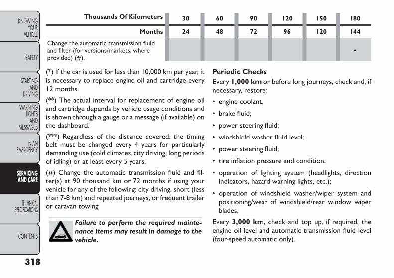
Thousands Of Kilometers 30 60 90 120 150 180
Months 24 48 72 96 120 144
Change the automatic transmission fluidand filter (for versions/markets, whereprovided) (#).
•
(*) If the car is used for less than 10,000 km per year, itis necessary to replace engine oil and cartridge every12 months.
(**) The actual interval for replacement of engine oiland cartridge depends by vehicle usage conditions andis shown through a gauge or a message (if available) onthe dashboard.
(***) Regardless of the distance covered, the timingbelt must be changed every 4 years for particularlydemanding use (cold climates, city driving, long periodsof idling) or at least every 5 years.
(#) Change the automatic transmission fluid and fil-ter(s) at 90 thousand km or 72 months if using yourvehicle for any of the following: city driving, short (lessthan 7-8 km) and repeated journeys, or frequent traileror caravan towing
Failure to perform the required mainte-nance items may result in damage to thevehicle.
Periodic ChecksEvery 1,000 km or before long journeys, check and, ifnecessary, restore:
• engine coolant;
• brake fluid;
• power steering fluid;
• windshield washer fluid level;
• power steering fluid;
• tire inflation pressure and condition;
• operation of lighting system (headlights, directionindicators, hazard warning lights, etc.);
• operation of windshield washer/wiper system andpositioning/wear of windshield/rear window wiperblades.
Every 3,000 km, check and top up, if required, theengine oil level and automatic transmission fluid level(four-speed automatic only).
318
KNOWINGYOUR
VEHICLE
SAFETY
STARTINGAND
DRIVING
WARNINGLIGHTS
ANDMESSAGES
IN ANEMERGENCY
SERVICINGAND CARE
TECHNICALSPECIFICATIONS
CONTENTS

Heavy-Duty Use OfThe CarIf the car is used mainly under one of the followingconditions:
• towing a trailer or caravan;
• dusty roads;
• short, repeated journeys (less than 7-8 km) at sub-zero outside temperatures;
• engine often idling or driving long distances at lowspeeds or long periods of idleness.
You should perform the following inspections morefrequently than shown on the Scheduled Servicing Plan:
• check front disc brake pad conditions and wear;
• check cleanliness of hood and trunk locks, cleanli-ness and lubrication of linkage;
• visually inspect conditions of: engine, transmission,pipes and hoses (exhaust - fuel system - brakes) andrubber elements (boots - sleeves - bushes - etc.);
• check battery charge and battery fluid level (electro-lyte);
• visually inspect condition of the accessory drivebelts;
• check and, if necessary, change engine oil and replaceoil filter;
• check and, if necessary, replace pollen filter;
• check and, if necessary, replace air cleaner.
319
KNOWINGYOURVEHICLE
SAFETY
STARTINGANDDRIVING
WARNINGLIGHTSANDMESSAGES
IN ANEMERGENCY
SERVICINGAND CARE
TECHNICALSPECIFICATIONS
CONTENTS

ENGINE COMPARTMENT — 2.4L(fig. 191)
(fig. 191)
1 — Engine Coolant Reservoir 7 — Power Distribution Center (Fuses)2 — Power Steering Fluid Reservoir 8 — Automatic Transmission Dipstick (4–Speed Only)3 — Engine Oil Fill 9 — Washer Fluid Reservoir4 — Brake Fluid Reservoir 10 — Coolant Pressure Cap5 — Remote Jump Start (Positive Battery Post) 11 — Engine Oil Dipstick6 — Remote Jump Start (Negative Battery Post)
320
KNOWINGYOUR
VEHICLE
SAFETY
STARTINGAND
DRIVING
WARNINGLIGHTS
ANDMESSAGES
IN ANEMERGENCY
SERVICINGAND CARE
TECHNICALSPECIFICATIONS
CONTENTS

ENGINE COMPARTMENT — 3.6L(fig. 192)
(fig. 192)
1 — Engine Coolant Reservoir 5 — Air Cleaner Filter2 — Power Steering Fluid Reservoir 6 — Washer Fluid Reservoir3 — Brake Fluid Reservoir 7 — Engine Oil Dipstick4 — Power Distribution Center (Fuses) 8 — Engine Oil Fill
321
KNOWINGYOURVEHICLE
SAFETY
STARTINGANDDRIVING
WARNINGLIGHTSANDMESSAGES
IN ANEMERGENCY
SERVICINGAND CARE
TECHNICALSPECIFICATIONS
CONTENTS

ENGINE COMPARTMENT — 2.0L DIESEL(fig. 193)
(fig. 193)
1 — Engine Coolant Reservoir 5 — Brake Fluid Reservoir2 — Power Steering Fluid Reservoir 6 — Power Distribution Center (Fuses)3 — Engine Oil Fill 7 — Air Cleaner Filter4 — Engine Oil Dipstick 8 — Washer Fluid Reservoir
322
KNOWINGYOUR
VEHICLE
SAFETY
STARTINGAND
DRIVING
WARNINGLIGHTS
ANDMESSAGES
IN ANEMERGENCY
SERVICINGAND CARE
TECHNICALSPECIFICATIONS
CONTENTS

MAINTENANCE PROCEDURESThe pages that follow contain the required mainte-nance services determined by the engineers who de-signed your vehicle.
Besides those maintenance items specified in the fixedmaintenance schedule, there are other componentswhich may require servicing or replacement in thefuture.
• Failure to properly maintain your ve-hicle or perform repairs and service whennecessary could result in more costly re-
pairs, damage to other components or negativelyimpact vehicle performance. Immediately havepotential malfunctions examined by an autho-rized dealership or qualified repair center.• Car maintenance should be done at a FIATDealership. For routine and minor maintenanceoperations you wish to carry out yourself, we dorecommend you have the proper equipment,genuine FIAT parts and the necessary fluids; donot however carry out these operations if youhave no experience.• Your vehicle has been built with improved fluidsthat protect the performance and durability ofyour vehicle and also allow extended mainte-nance intervals. Do not use chemical flushes inthese components as the chemicals can damageyour engine, transmission, power steering or airconditioning. Such damage is not covered by theNewVehicle LimitedWarranty. If a flush is neededbecause of component malfunction, use only thespecified fluid for the flushing procedure.
323
KNOWINGYOURVEHICLE
SAFETY
STARTINGANDDRIVING
WARNINGLIGHTSANDMESSAGES
IN ANEMERGENCY
SERVICINGAND CARE
TECHNICALSPECIFICATIONS
CONTENTS

ENGINE OIL
Checking Oil Level – Gasoline EngineTo assure proper engine lubrication, the engine oilmust be maintained at the correct level. Check the oillevel at regular intervals, such as every fuel stop.
The best time to check the engine oil level is about fiveminutes after a fully warmed engine is shut off. Do notcheck oil level before starting the engine after it has satovernight. Checking engine oil level when the engine iscold will give you an incorrect reading.
Checking the oil while the vehicle is on level groundand only when the engine is hot, will improve theaccuracy of the oil level readings. Maintain the oil levelbetween the range markings on the dipstick. Either therange markings consist of a crosshatch zone markedSAFE or a crosshatch zone marked with MIN at the lowend of the range and MAX at the high end of the range.Adding 1 Quart or 1 Liter of oil when the reading is atthe low end of the range marking will raise the oil levelto the high end of the range marking.
Do not overfill the engine.Overfilling theengine will cause oil aeration, which canlead to loss of oil pressure and an in-
crease in oil temperature.This could damage yourengine.Also,be sure the oil fill cap is replaced andtightened after adding oil.
Checking Oil Level – Diesel EngineTo assure proper engine lubrication, the engine oilmust be maintained at the correct level. Check the oillevel at regular intervals, such as every fuel stop.
The best time to check the engine oil level is about fiveminutes after a fully warmed engine is shut off orbefore starting the engine after it has sat overnight.
Checking the oil while the vehicle is on level ground willimprove the accuracy of the oil level readings. Maintainthe oil level between the MIN and MAX markings onthe dipstick. Adding 1 Quart or 1 Liter of oil when thereading is at the MIN mark will result in a MAX readingon these engines.
324
KNOWINGYOUR
VEHICLE
SAFETY
STARTINGAND
DRIVING
WARNINGLIGHTS
ANDMESSAGES
IN ANEMERGENCY
SERVICINGAND CARE
TECHNICALSPECIFICATIONS
CONTENTS

Car maintenance should be done at aFIAT Dealership. For routine and minormaintenance operations you wish to
carry out yourself, we do recommend you havethe proper equipment, genuine FIAT spare partsand the necessary fluids;do not however carry outthese operations if you have no experience.
Change Engine Oil – Gasoline EngineRefer to the “Maintenance Schedule” for the propermaintenance intervals.
Change Engine Oil – Diesel EngineRefer to the “Maintenance Schedule” for the propermaintenance intervals.
Engine OilViscosity – 2.4L And 3.6L GasolineEngineSAE Grade 5W-20 SELENIA K POWER fully syntheticengine oil that meets FIAT Qualification 9.55535-CR1API SN, ILSAC GF-5 or equivalent.
The engine oil filler cap also shows the recommendedengine oil viscosity for your vehicle. For information onengine oil filler cap location, refer to “Engine Compart-ment” in “Servicing And Care” for further information.
NOTE: SAE Grade 5W-30 SELENIA K POWER fullysynthetic engine oil that meets FIAT Qualification9.55535-CR1 API SN, ILSAC GF-5 may be used whenSAE 5W-20 engine oil meeting Fiat 9.55535-CR1 is notavailable.
Engine OilViscosity – 2.0L Diesel EngineSAE Grade 5W-30 SELENIA WR P.E. fully syntheticengine oil that meets FIAT Qualification 9.55535–S1,ACEA C2 or equivalent.
The engine oil filler cap also shows the recommendedengine oil viscosity for your engine. For information onengine oil filler cap location, refer to “Engine Compart-ment” in “Servicing and Care” for further information.
Change Engine Oil – Diesel EngineRefer to the “Maintenance Schedule” for the propermaintenance intervals.
Materials AddedTo Engine OilDo not add any supplemental materials, other than leakdetection dyes, to the engine oil. Engine oil is anengineered product and its performance may be im-paired by supplemental additives.
325
KNOWINGYOURVEHICLE
SAFETY
STARTINGANDDRIVING
WARNINGLIGHTSANDMESSAGES
IN ANEMERGENCY
SERVICINGAND CARE
TECHNICALSPECIFICATIONS
CONTENTS
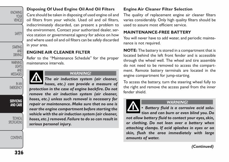
Disposing Of Used Engine Oil And Oil FiltersCare should be taken in disposing of used engine oil andoil filters from your vehicle. Used oil and oil filters,indiscriminately discarded, can present a problem tothe environment. Contact your authorized dealer, ser-vice station or governmental agency for advice on howand where used oil and oil filters can be safely discardedin your area.
ENGINE AIR CLEANER FILTERRefer to the “Maintenance Schedule” for the propermaintenance intervals.
WARNING!The air induction system (air cleaner,hoses, etc.) can provide a measure of
protection in the case of engine backfire. Do notremove the air induction system (air cleaner,hoses, etc.) unless such removal is necessary forrepair or maintenance. Make sure that no one isnear the engine compartment before starting thevehicle with the air induction system (air cleaner,hoses,etc.) removed.Failure to do so can result inserious personal injury.
Engine Air Cleaner Filter SelectionThe quality of replacement engine air cleaner filtersvaries considerably. Only high quality filters should beused to assure most efficient service.
MAINTENANCE-FREE BATTERYYou will never have to add water, and periodic mainte-nance is not required.
NOTE: The battery is stored in a compartment that islocated behind the left front fender and is accessiblethrough the wheel well. The wheel and tire assembledo not need to be removed to access the compart-ment. Remote battery terminals are located in theengine compartment for jump-starting.
To access the battery, turn the steering wheel fully tothe right and remove the access panel from the innerfender shield.
WARNING!• Battery fluid is a corrosive acid solu-tion and can burn or even blind you. Do
not allow battery fluid to contact your eyes, skin,or clothing. Do not lean over a battery whenattaching clamps. If acid splashes in eyes or onskin, flush the area immediately with largeamounts of water.
(Continued)
326
KNOWINGYOUR
VEHICLE
SAFETY
STARTINGAND
DRIVING
WARNINGLIGHTS
ANDMESSAGES
IN ANEMERGENCY
SERVICINGAND CARE
TECHNICALSPECIFICATIONS
CONTENTS

(Continued)• Battery gas is flammable and explosive. Keepflame or sparks away from the battery. Do notuse a booster battery or any other booster sourcewith an output greater than 12 Volts. Do notallow cable clamps to touch each other.• Battery posts, terminals, and related accesso-ries contain lead and lead compounds. Washhands after handling.
• It is essential when replacing the cableson the battery that the positive cable isattached to the positive post and the
negative cable is attached to the negative post.Battery posts are marked positive (+) and nega-tive (-) and identified on the battery case. Cableclamps should be tight on the terminal posts andfree of corrosion.• If a “fast charger” is used while the battery is inthe vehicle,disconnect both vehicle battery cablesbefore connecting the charger to the battery. Donot use a “fast charger” to provide starting volt-age as battery damage can result.
AIR CONDITIONER MAINTENANCEFor best possible performance, your air conditionershould be checked and serviced by an authorizeddealer at the start of each warm season. This serviceshould include cleaning of the condenser fins and aperformance test. Drive belt tension should also bechecked at this time.
Do not use chemical flushes in your airconditioning system as the chemicals candamage your air conditioning compo-
nents. Such damage is not covered by the NewVehicle LimitedWarranty.
WARNING!• Use only refrigerants and compressorlubricants approved by the manufac-
turer for your air conditioning system. Some un-approved refrigerants are flammable and canexplode, injuring you. Other unapproved refrig-erants or lubricants can cause the system to fail,requiring costly repairs.• The air conditioning system contains refrigerantunder high pressure. To avoid risk of personalinjury or damage to the system,adding refrigerantor any repair requiring lines to be disconnectedshould be done by an experienced technician.
327
KNOWINGYOURVEHICLE
SAFETY
STARTINGANDDRIVING
WARNINGLIGHTSANDMESSAGES
IN ANEMERGENCY
SERVICINGAND CARE
TECHNICALSPECIFICATIONS
CONTENTS

Refrigerant Recovery And RecyclingR-134a Air Conditioning Refrigerant is a hydrofluoro-carbon (HFC) that is endorsed by the EnvironmentalProtection Agency and is an ozone-saving product.However, the manufacturer recommends that air con-ditioning service be performed by authorized dealer orother service facilities using recovery and recyclingequipment.
NOTE: Use only manufacturer approved A/C systemPAG compressor oil and refrigerants.
A/C AIR FILTERRefer to the “Maintenance Schedule” for the propermaintenance intervals.
Car maintenance should be done at aFIAT Dealership. For routine and minormaintenance operations you wish to
carry out yourself, we do recommend you havethe proper equipment, genuine FIAT spare partsand the necessary fluids;do not however carry outthese operations if you have no experience.
WARNING!Do not remove the A/C air filter while theblower is operating or personal injury
may result.
The A/C air filter is located in the fresh air inlet behindthe glove box. Perform the following steps to replacethe filter:
1. Open the glove box and remove all contents.
2. Push the retaining tab on each side of the glove boxinward while gently pulling the glove box dooroutward until both tabs clear the door opening inthe instrument panel. (fig. 194)
(fig. 194)Glove Box Removal
328
KNOWINGYOUR
VEHICLE
SAFETY
STARTINGAND
DRIVING
WARNINGLIGHTS
ANDMESSAGES
IN ANEMERGENCY
SERVICINGAND CARE
TECHNICALSPECIFICATIONS
CONTENTS

3. Pivot the glove box downward.
4. Disengage the two retaining tabs that secure thefilter cover to the HVAC housing and remove thecover. (fig. 195)
5. Remove the A/C air filter by pulling it straight out ofthe housing.
6. Install the A/C air filter with the arrow on the filterpointing toward the floor. When installing the filtercover, make sure the retaining tabs fully engage thecover.
TheA/C air filter is identified with an arrowto indicate airflow direction through thefilter. Failure to install the filter properly
will result in the need to replace it more often.
7. Reinstall the glove box door. Make sure that thehinges are seated fully as you raise the door. Other-wise, the door latch will not align properly.
BODY LUBRICATIONLocks and all body pivot points, including such items asseat tracks, door hinge pivot points and rollers, liftgate,tailgate, sliding doors and hood hinges, should belubricated periodically with a lithium based grease toassure quiet, easy operation and to protect against rustand wear. Prior to the application of any lubricant, theparts concerned should be wiped clean to remove dustand grit; after lubricating excess oil and grease shouldbe removed. Particular attention should also be givento hood latching components to ensure proper func-tion. When performing other underhood services, thehood latch, release mechanism and safety catch shouldbe cleaned and lubricated.
The external lock cylinders should be lubricated twicea year, preferably in the Fall and Spring. Apply a smallamount of a high quality lubricant directly into the lockcylinder.
(fig. 195)A/C Air Filter Replacement
329
KNOWINGYOURVEHICLE
SAFETY
STARTINGANDDRIVING
WARNINGLIGHTSANDMESSAGES
IN ANEMERGENCY
SERVICINGAND CARE
TECHNICALSPECIFICATIONS
CONTENTS

Car maintenance should be done at aFIAT Dealership. For routine and minormaintenance operations you wish to
carry out yourself, we do recommend you havethe proper equipment, genuine FIAT spare partsand the necessary fluids;do not however carry outthese operations if you have no experience.
WIPER BLADESClean the rubber edges of the wiper blades and thewindshield and rear window periodically with a spongeor soft cloth and a mild nonabrasive cleaner. This willremove accumulations of salt, waxes, or road film, andhelp reduce streaking and smearing.
Operation of the wipers on dry glass for long periodsmay cause deterioration of the wiper blades. Alwaysuse washer fluid when using the wipers to remove saltor dirt from a dry windshield or rear window.
Avoid using the wiper blades to remove frost or icefrom the windshield or rear window. Make sure thatthey are not frozen to the glass before turning them onto avoid damaging the blade. Keep the blade rubber outof contact with petroleum products such as engine oil,gasoline, etc.
NOTE: Life expectancy of wiper blades varies depend-ing on geographical area and frequency of use. Poorperformance of blades may be present with chattering,marks, water lines or wet spots. If any of these condi-tions are present, clean the wiper blades or replace asnecessary.
Rear Wiper Removal/Installation
1. Lift the pivot cap on the rear wiper arm upward, thiswill allow the rear wiper blade to be raised off of theliftgate glass. (fig. 196)
NOTE: The rear wiper arm cannot be raised fullyupward unless the pivot cap is raised first.
(fig. 196)
1 — Wiper Arm2 — Pivot Cap
330
KNOWINGYOUR
VEHICLE
SAFETY
STARTINGAND
DRIVING
WARNINGLIGHTS
ANDMESSAGES
IN ANEMERGENCY
SERVICINGAND CARE
TECHNICALSPECIFICATIONS
CONTENTS

2. Lift the rear wiper arm upward to raise the wiperblade off of the liftgate glass.
3. Grab the bottom of the wiper blade and rotate itforward to unsnap the blade pivot pin from thewiper blade holder. (fig. 197)
4. Install the wiper blade pivot pin into the wiper bladeholder at the end of the wiper arm, and firmly pressthe wiper blade until it snaps into place.
5. Lower the wiper blade and snap the pivot cap intoplace.
ADDING WASHER FLUIDThe windshield washer and the rear window washershare the same fluid reservoir. The fluid reservoir islocated in the engine compartment. Be sure to checkthe fluid level in the reservoir at regular intervals. Fillthe reservoir with windshield washer solvent (notradiator antifreeze) and operate the system for a fewseconds to flush out the residual water.
When refilling the washer fluid reservoir, apply somewasher fluid to a cloth or towel and wipe the wiperblades clean. This will help blade performance.
To prevent freeze-up of your windshield washer systemin cold weather, select a solution or mixture that meetsor exceeds the temperature range of your climate. Thisrating information can be found on most washer fluidcontainers.
The fluid reservoir will hold nearly 4 Liters of washerfluid when the “Washer Fluid Low” message appears inthe EVIC display.
WARNING!Commercially available windshield washersolvents are flammable.They could ignite
and burn you.Care must be exercised when filling orworking around the washer solution.
(fig. 197)
1 — Wiper Blade2 — Blade Pivot Pin3 — Wiper Arm4 — Wiper Blade Holder
331
KNOWINGYOURVEHICLE
SAFETY
STARTINGANDDRIVING
WARNINGLIGHTSANDMESSAGES
IN ANEMERGENCY
SERVICINGAND CARE
TECHNICALSPECIFICATIONS
CONTENTS

Car maintenance should be done at aFIAT Dealership. For routine and minormaintenance operations you wish to
carry out yourself, we do recommend you havethe proper equipment, genuine FIAT spare partsand the necessary fluids;do not however carry outthese operations if you have no experience.
INTERVENTION REGENERATIONSTRATEGY – 2.0L DIESEL ENGINEThis vehicle is equipped with a state-of-the-art engineand exhaust system containing a diesel particulatefilter. The engine and exhaust after-treatment systemwork together to meet the Emission standards. Thesystem manages engine combustion to allow the ex-haust system’s catalyst to trap and burn ParticulateMatter (PM) pollutants with no input or interaction onyour part.
Refer to “Electronic Vehicle Information Center(EVIC)” in “Knowing Your Vehicle” for further informa-tion.
EXHAUST SYSTEMThe best protection against carbon monoxide entryinto the vehicle body is a properly maintained engineexhaust system.
Whenever a change is noticed in the sound of theexhaust system, when exhaust fumes can be detectedinside the vehicle, or when the underside or rear of thevehicle is damaged, have a competent technician in-spect the complete exhaust system and adjacent bodyareas for broken, damaged, deteriorated, or misposi-tioned parts. Open seams or loose connections couldpermit exhaust fumes to seep into the passenger com-partment. In addition, inspect the exhaust system eachtime the vehicle is raised for lubrication or oil change.Replace as required.
WARNING!Exhaust gases can injure or kill. Theycontain carbon monoxide (CO), which is
colorless and odorless.Breathing it can make youunconscious and can eventually poison you. Toavoid breathing CO,refer to“SafetyTips/ExhaustGas” in “Safety” for further information.
NOTE: Intentional tampering with emissions controlsystems can result in civil penalties being assessedagainst you.
332
KNOWINGYOUR
VEHICLE
SAFETY
STARTINGAND
DRIVING
WARNINGLIGHTS
ANDMESSAGES
IN ANEMERGENCY
SERVICINGAND CARE
TECHNICALSPECIFICATIONS
CONTENTS

WARNING!A hot exhaust system can start a fire ifyou park over materials that can burn.
Such materials might be grass or leaves cominginto contact with your exhaust system. Do notpark or operate your vehicle in areas where yourexhaust system can contact anything that canburn.
In unusual situations involving grossly malfunctioningengine operation, a scorching odor may indicate severeand abnormal catalyst overheating. If this occurs, safelybring the vehicle to a complete stop, shut the engineOFF, and allow the vehicle to cool. Thereafter, obtainservice, including a tune-up to manufacturer’s specifi-cations immediately.
To minimize the possibility of catalyst damage:
• Do not shut OFF the engine or interrupt the ignitionwhen the transmission is in gear and the vehicle is inmotion.
• Do not try to start the engine by pushing or towingthe vehicle.
• Do not idle the engine with any ignition coil connec-tors disconnected for prolonged periods.
COOLING SYSTEM
WARNING!• When working near the radiator cool-ing fan, disconnect the fan motor lead or
turn the ignition switch to the LOCK position.The fan is temperature controlled and can start atany time the ignition switch is in the ON position.• You or others can be badly burned by hotengine coolant (antifreeze) or steam from yourradiator. If you see or hear steam coming fromunder the hood, do not open the hood until theradiator has had time to cool.Never try to open acooling system pressure cap when the radiator ishot.
Car maintenance should be done at aFIAT Dealership. For routine and minormaintenance operations you wish to
carry out yourself, we do recommend you havethe proper equipment, genuine FIAT spare partsand the necessary fluids;do not however carry outthese operations if you have no experience.
333
KNOWINGYOURVEHICLE
SAFETY
STARTINGANDDRIVING
WARNINGLIGHTSANDMESSAGES
IN ANEMERGENCY
SERVICINGAND CARE
TECHNICALSPECIFICATIONS
CONTENTS
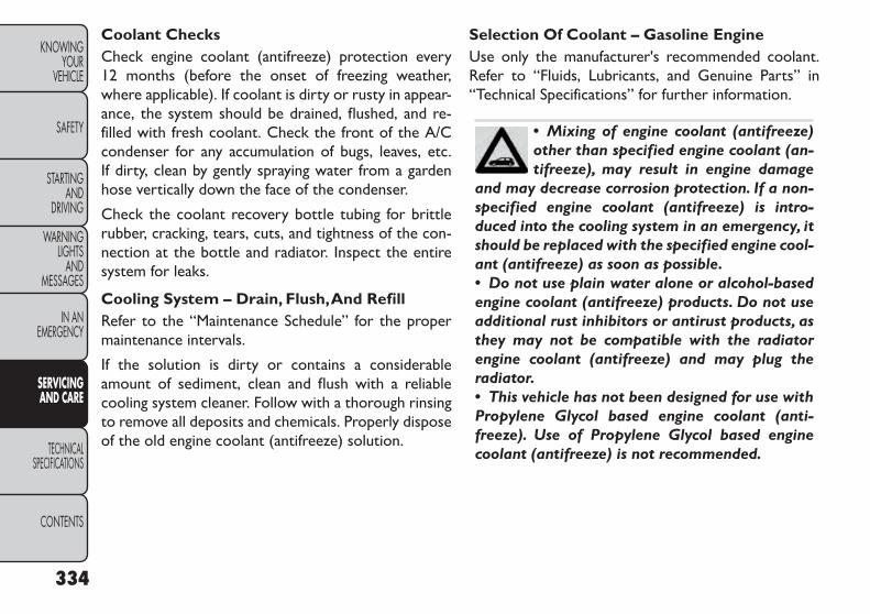
Coolant ChecksCheck engine coolant (antifreeze) protection every12 months (before the onset of freezing weather,where applicable). If coolant is dirty or rusty in appear-ance, the system should be drained, flushed, and re-filled with fresh coolant. Check the front of the A/Ccondenser for any accumulation of bugs, leaves, etc.If dirty, clean by gently spraying water from a gardenhose vertically down the face of the condenser.
Check the coolant recovery bottle tubing for brittlerubber, cracking, tears, cuts, and tightness of the con-nection at the bottle and radiator. Inspect the entiresystem for leaks.
Cooling System – Drain, Flush,And RefillRefer to the “Maintenance Schedule” for the propermaintenance intervals.
If the solution is dirty or contains a considerableamount of sediment, clean and flush with a reliablecooling system cleaner. Follow with a thorough rinsingto remove all deposits and chemicals. Properly disposeof the old engine coolant (antifreeze) solution.
Selection Of Coolant – Gasoline EngineUse only the manufacturer's recommended coolant.Refer to “Fluids, Lubricants, and Genuine Parts” in“Technical Specifications” for further information.
• Mixing of engine coolant (antifreeze)other than specified engine coolant (an-tifreeze), may result in engine damage
and may decrease corrosion protection. If a non-specified engine coolant (antifreeze) is intro-duced into the cooling system in an emergency, itshould be replaced with the specified engine cool-ant (antifreeze) as soon as possible.• Do not use plain water alone or alcohol-basedengine coolant (antifreeze) products. Do not useadditional rust inhibitors or antirust products, asthey may not be compatible with the radiatorengine coolant (antifreeze) and may plug theradiator.• This vehicle has not been designed for use withPropylene Glycol based engine coolant (anti-freeze). Use of Propylene Glycol based enginecoolant (antifreeze) is not recommended.
334
KNOWINGYOUR
VEHICLE
SAFETY
STARTINGAND
DRIVING
WARNINGLIGHTS
ANDMESSAGES
IN ANEMERGENCY
SERVICINGAND CARE
TECHNICALSPECIFICATIONS
CONTENTS
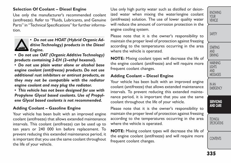
Selection Of Coolant – Diesel EngineUse only the manufacturer's recommended coolant(antifreeze). Refer to “Fluids, Lubricants, and GenuineParts” in “Technical Specifications” for further informa-tion.
• Do not use HOAT (Hybrid Organic Ad-ditiveTechnology) products in the DieselEngine.
• Do not use OAT (Organic Additive Technology)products containing 2-EH (2–ethyl hexanol).• Do not use plain water alone or alcohol baseengine coolant (antifreeze) products. Do not useadditional rust inhibitors or antirust products, asthey may not be compatible with the radiatorengine coolant and may plug the radiator.• This vehicle has not been designed for use withPropylene Glycol based coolants. Use of Propyl-ene Glycol based coolants is not recommended.
Adding Coolant – Gasoline EngineYour vehicle has been built with an improved enginecoolant (antifreeze) that allows extended maintenanceintervals. This coolant (antifreeze) can be used up toten years or 240 000 km before replacement. Toprevent reducing this extended maintenance period, itis important that you use the same coolant throughoutthe life of your vehicle.
Use only high purity water such as distilled or deion-ized water when mixing the water/engine coolant(antifreeze) solution. The use of lower quality waterwill reduce the amount of corrosion protection in theengine cooling system.
Please note that it is the owner's responsibility tomaintain the proper level of protection against freezingaccording to the temperatures occurring in the areawhere the vehicle is operated.
NOTE: Mixing coolant types will decrease the life ofthe engine coolant (antifreeze) and will require morefrequent coolant changes.
Adding Coolant – Diesel EngineYour vehicle has been built with an improved enginecoolant (antifreeze) that allows extended maintenanceintervals. To prevent reducing this extended mainte-nance period, it is important that you use the samecoolant throughout the life of your vehicle.
Please note that it is the owner's responsibility tomaintain the proper level of protection against freezingaccording to the temperatures occurring in the areawhere the vehicle is operated.
NOTE: Mixing coolant types will decrease the life ofthe engine coolant (antifreeze) and will require morefrequent coolant changes.
335
KNOWINGYOURVEHICLE
SAFETY
STARTINGANDDRIVING
WARNINGLIGHTSANDMESSAGES
IN ANEMERGENCY
SERVICINGAND CARE
TECHNICALSPECIFICATIONS
CONTENTS

Cooling System Pressure CapThe cap must be fully tightened to prevent loss ofengine coolant (antifreeze), and to ensure that enginecoolant (antifreeze) will return to the radiator from thecoolant recovery tank.
The cap should be inspected and cleaned if there is anyaccumulation of foreign material on the sealing sur-faces.
WARNING!• The warning words “DO NOT OPENHOT” on the cooling system pressure
cap are a safety precaution. Never add enginecoolant (antifreeze) when the engine is over-heated. Do not loosen or remove the cap to coolan overheated engine. Heat causes pressure tobuild up in the cooling system.To prevent scaldingor injury, do not remove the pressure cap whilethe system is hot or under pressure.• Do not use a pressure cap other than the onespecified for your vehicle. Personal injury or en-gine damage may result.
Disposal Of Used CoolantUsed ethylene glycol-based engine coolant is a regu-lated substance requiring proper disposal. Check withyour local authorities to determine the disposal rulesfor your community. To prevent ingestion by animals orchildren, do not store ethylene glycol-based enginecoolant in open containers or allow it to remain inpuddles on the ground. If ingested by a child, contact aphysician immediately. Clean up any ground spills im-mediately.
Coolant LevelThe radiator normally remains completely full, so thereis no need to remove the radiator cap unless checkingfor coolant freeze point or replacing coolant. Adviseyour service attendant of this. As long as the engineoperating temperature is satisfactory, the coolantbottle need only be checked once a month. Whenadditional coolant is needed to maintain the properlevel, it should be added to the coolant bottle. Do notoverfill.
336
KNOWINGYOUR
VEHICLE
SAFETY
STARTINGAND
DRIVING
WARNINGLIGHTS
ANDMESSAGES
IN ANEMERGENCY
SERVICINGAND CARE
TECHNICALSPECIFICATIONS
CONTENTS
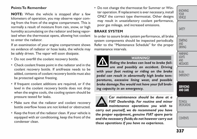
PointsTo Remember
NOTE: When the vehicle is stopped after a fewkilometers of operation, you may observe vapor com-ing from the front of the engine compartment. This isnormally a result of moisture from rain, snow, or highhumidity accumulating on the radiator and being vapor-ized when the thermostat opens, allowing hot coolantto enter the radiator.If an examination of your engine compartment showsno evidence of radiator or hose leaks, the vehicle maybe safely driven. The vapor will soon dissipate.
• Do not overfill the coolant recovery bottle.
• Check coolant freeze point in the radiator and in thecoolant recovery bottle. If antifreeze needs to beadded, contents of coolant recovery bottle must alsobe protected against freezing.
• If frequent coolant additions are required, or if thelevel in the coolant recovery bottle does not dropwhen the engine cools, the cooling system should bepressure tested for leaks.
• Make sure that the radiator and coolant recoverybottle overflow hoses are not kinked or obstructed.
• Keep the front of the radiator clean. If your vehicle isequipped with air conditioning, keep the front of thecondenser clean.
• Do not change the thermostat for Summer or Win-ter operation. If replacement is ever necessary, installONLY the correct type thermostat. Other designsmay result in unsatisfactory coolant performance,poor gas mileage, and increased emissions.
BRAKE SYSTEMIn order to assure brake system performance, all brakesystem components should be inspected periodically.Refer to the “Maintenance Schedule” for the propermaintenance intervals.
WARNING!Riding the brakes can lead to brake fail-ure and possibly an accident. Driving
with your foot resting or riding on the brakepedal can result in abnormally high brake tem-peratures, excessive lining wear, and possiblebrake damage.You would not have your full brak-ing capacity in an emergency.
Car maintenance should be done at aFIAT Dealership. For routine and minormaintenance operations you wish to
carry out yourself, we do recommend you havethe proper equipment, genuine FIAT spare partsand the necessary fluids;do not however carry outthese operations if you have no experience.
337
KNOWINGYOURVEHICLE
SAFETY
STARTINGANDDRIVING
WARNINGLIGHTSANDMESSAGES
IN ANEMERGENCY
SERVICINGAND CARE
TECHNICALSPECIFICATIONS
CONTENTS

Master Cylinder – Brake Fluid Level CheckCheck the fluid level in the master cylinder immediatelyif the “Brake Warning Light” indicates system failure.
Check the fluid level in the master cylinder whenperforming underhood services.
Clean the top of the master cylinder area beforeremoving the cap. If necessary, add fluid to bring thefluid level up to the requirements described on thebrake fluid reservoir.
Overfilling of fluid is not recommended because it maycause leaking in the system.
Fluid level can be expected to fall as the brake padswear. Brake fluid level should be checked when pads arereplaced. However, low fluid level may be caused by aleak and a checkup may be needed.
NOTE: If your vehicle is equipped with a manualtransmission, the brake fluid reservoir supplies fluidto both the brake system and the clutch release sys-tem. The two systems are separated in the reservoir,and a leak in one system will not affect the othersystem. The manual transmission clutch releasesystem should not require fluid replacement during thelife of the vehicle. If the brake fluid reservoir is low andthe brake system does not indicate any leaks or otherproblems, it may be a result of a leak in the hydraulic
clutch release system. See your local authorized dealerfor service.
Use only manufacturer's recommended brake fluid.Refer to “Fluids, Lubricants, and Genuine Parts” in“Technical Specifications” for further information.
WARNING!• Use only manufacturer's recom-mended brake fluid. Refer to “Fluids, Lu-
bricants,and Genuine Parts” in“Technical Speci-fications” for further information. Using thewrong type of brake fluid can severely damageyour brake system and/or impair its perfor-mance.The proper type of brake fluid for yourvehicle is also identified on the original factoryinstalled hydraulic master cylinder reservoir.• To avoid contamination from foreign matter ormoisture, use only new brake fluid or fluid thathas been in a tightly closed container. Keep themaster cylinder reservoir cap secured at alltimes. Brake fluid in a open container absorbsmoisture from the air resulting in a lower boilingpoint. This may cause it to boil unexpectedlyduring hard or prolonged braking, resulting insudden brake failure.This could result in a acci-dent.
(Continued)
338
KNOWINGYOUR
VEHICLE
SAFETY
STARTINGAND
DRIVING
WARNINGLIGHTS
ANDMESSAGES
IN ANEMERGENCY
SERVICINGAND CARE
TECHNICALSPECIFICATIONS
CONTENTS

(Continued)• Overfilling the brake fluid reservoir can resultin spilling brake fluid on hot engine parts,causingthe brake fluid to catch fire. Brake fluid can alsodamage painted and vinyl surfaces, care shouldbe taken to avoid its contact with these surfaces.• Do not allow petroleum based fluid to con-taminate the brake fluid. Brake seal componentscould be damaged, causing partial or completebrake failure.This could result in an accident.
AUTOMATICTRANSMISSION(for versions/markets, where provided)
Selection Of LubricantIt is important to use the proper transmission fluid toensure optimum transmission performance and life.Use only the manufacturer’s specified transmissionfluid. Refer to “Fluids, Lubricants, and Genuine Parts”in “Technical Specifications” for fluid specifications. It isimportant to maintain the transmission fluid at thecorrect level using the recommended fluid. No chemi-cal flushes should be used in any transmission; only theapproved lubricant should be used.
Using a transmission fluid other than themanufacturer’s recommended fluid maycause deterioration in transmission shift
quality and/or torque converter shudder, and willrequire more frequent fluid and filter changes.Refer to“Fluids,Lubricants,and Genuine Parts”in"Technical Specifications" for fluid specifica-tions.
Special AdditivesThe manufacturer strongly recommends against usingany special additives in the transmission. AutomaticTransmission Fluid (ATF) is an engineered product andits performance may be impaired by supplemental ad-ditives. Therefore, do not add any fluid additives to thetransmission. The only exception to this policy is theuse of special dyes for diagnosing fluid leaks. Avoidusing transmission sealers as they may adversely affectseals.
Do not use chemical flushes in yourtransmission as the chemicals can dam-age your transmission components. Such
damage is not covered by the NewVehicle LimitedWarranty.
339
KNOWINGYOURVEHICLE
SAFETY
STARTINGANDDRIVING
WARNINGLIGHTSANDMESSAGES
IN ANEMERGENCY
SERVICINGAND CARE
TECHNICALSPECIFICATIONS
CONTENTS

Fluid Level Check - Six-SpeedTransmissionThe fluid level is preset at the factory and does notrequire adjustment under normal operating conditions.Routine fluid level checks are not required, thereforethe transmission filler tube is capped and no dipstick isprovided. Your authorized dealer can check your trans-mission fluid level using a special service dipstick. If younotice fluid leakage or transmission malfunction, visityour authorized dealer immediately to have the trans-mission fluid level checked. Operating the vehicle withan improper fluid level can cause severe transmissiondamage.
If a transmission fluid leak occurs, visityour authorized dealer immediately.Severe transmission damage may occur.
Your authorized dealer has the proper tools toadjust the fluid level accurately.
Car maintenance should be done at aFIAT Dealership. For routine and minormaintenance operations you wish to
carry out yourself, we do recommend you havethe proper equipment, genuine FIAT spare partsand the necessary fluids;do not however carry outthese operations if you have no experience.
Fluid Level Check – Four-Speed AutomaticUse the following procedure to check the transmissionfluid level properly:
1. Park the vehicle on level ground.
2. Run the engine at normal idle speed for at least60 seconds, and leave the engine running for the restof this procedure.
3. Fully apply the parking brake, and press the brakepedal.
4. Place the shift lever momentarily into each gearposition (allowing time for the transmission to fullyengage in each position), ending with the transmis-sion in PARK.
5. Wipe the area around the dipstick clean to preventdirt from entering the transmission.
6. Remove the dipstick and determine if the fluid ishot or cold. Hot fluid is approximately 82° C, whichis the normal operating temperature after the ve-hicle is driven at least 24 km. Hot fluid cannot beheld comfortably between the fingertips. Cold fluidis at a temperature of approximately 27° C.
340
KNOWINGYOUR
VEHICLE
SAFETY
STARTINGAND
DRIVING
WARNINGLIGHTS
ANDMESSAGES
IN ANEMERGENCY
SERVICINGAND CARE
TECHNICALSPECIFICATIONS
CONTENTS
7. Wipe the dipstick clean and reinsert it until seated.Then, remove the dipstick and note the fluid levelon both sides. The fluid level reading is only valid ifthere is a solid coating of oil on both sides of thedipstick. Note that the holes in the dipstick will befull of fluid if the actual level is at or above the hole.
• If the fluid is hot, the fluid level should be in thecrosshatched area marked “HOT” (between the up-per two holes in the dipstick).
• If the fluid is cold, the fluid level should be betweenthe lower two holes in the area marked “COLD.”If the fluid level is low, add fluid through the dipsticktube to bring it to the proper level. Do not overfill.After adding any quantity of oil through the dipsticktube, wait at least two minutes for the oil to fullydrain into the transmission before rechecking thefluid level.
8. Check for leaks. Release the parking brake.
To prevent dirt and water from entering the transmis-sion after checking or replenishing fluid, make sure thatthe dipstick cap is properly re-seated.
• Using a transmission fluid other thanthe manufacturer’s recommended fluidmay cause deterioration in transmission
shift quality and/or torque converter shudder,andwill require more frequent fluid and filterchanges.Refer to“Fluids,Lubricants,and GenuineParts” in "Technical Specifications" for fluidspecifications.• Dirt and water in the transmission can causeserious damage.To prevent dirt and water fromentering the transmission after checking or re-plenishing fluid,make sure that the dipstick cap isre-seated properly.
Fluid And Filter ChangesRefer to the “Maintenance Schedule” for the propermaintenance intervals.
In addition, change the fluid and filter if the fluidbecomes contaminated (with water, etc.), or if thetransmission is disassembled for any reason.
341
KNOWINGYOURVEHICLE
SAFETY
STARTINGANDDRIVING
WARNINGLIGHTSANDMESSAGES
IN ANEMERGENCY
SERVICINGAND CARE
TECHNICALSPECIFICATIONS
CONTENTS

MANUALTRANSMISSION(for versions/markets, where provided)
Lubricant SelectionUse only manufacturers recommended transmissionfluid. Do not add any materials (other than leak detec-tion dyes). Refer to “Fluids, Lubricants, and GenuineParts” in “Technical Specifications” for further informa-tion.
Frequency Of Fluid ChangeChange the manual transmission fluid at the intervalsshown in the “Maintenance Schedule” in this manual.
REAR DRIVE ASSEMBLY (RDA) –AWD MODELS ONLY
Lubricant SelectionUse only the manufacturer's recommended fluid. Referto “Fluids, Lubricants, and Genuine Parts” in “TechnicalSpecifications” for further information.
Fluid Level CheckVisually inspect the unit at each oil change for leakage.If leakage is detected, check the fluid level by removingthe fill plug. The fluid level should be maintained be-tween the bottom of the fill hole to 4 mm below the fillhole.
Add fluid, if necessary, to maintain the proper level.
Frequency Of Fluid ChangeRefer to the “Maintenance Schedule” for the propermaintenance intervals.
POWERTRANSFER UNIT (PTU) –AWD MODELS ONLY
Lubricant SelectionUse only the manufacturer's recommended fluid. Referto “Fluids, Lubricants, and Genuine Parts” in “TechnicalSpecifications” for further information.
Fluid Level CheckVisually inspect the unit at each oil change for leakage.If leakage is detected, Check the fluid level by removingthe fill plug. The fluid level should be maintained be-tween the bottom of the fill hole to 4 mm below the fillhole.
Add fluid, if necessary, to maintain the proper level.
Frequency Of Fluid ChangeRefer to the “Maintenance Schedule” for the propermaintenance intervals.
342
KNOWINGYOUR
VEHICLE
SAFETY
STARTINGAND
DRIVING
WARNINGLIGHTS
ANDMESSAGES
IN ANEMERGENCY
SERVICINGAND CARE
TECHNICALSPECIFICATIONS
CONTENTS

APPEARANCE CARE AND PROTECTIONFROM CORROSION
Protection Of Body And Paint From CorrosionVehicle body care requirements vary according to geo-graphic locations and usage. Chemicals that make roadspassable in snow and ice and those that are sprayed ontrees and road surfaces during other seasons are highlycorrosive to the metal in your vehicle. Outside parking,which exposes your vehicle to airborne contaminants,road surfaces on which the vehicle is operated, ex-treme hot or cold weather and other extreme condi-tions will have an adverse effect on paint, metal trim,and underbody protection.
The following maintenance recommendations will en-able you to obtain maximum benefit from the corro-sion resistance built into your vehicle.
What Causes Corrosion?Corrosion is the result of deterioration or removal ofpaint and protective coatings from your vehicle.
The most common causes are:
• Road salt, dirt and moisture accumulation.
• Stone and gravel impact.
• Insects, tree sap and tar.
• Salt in the air near seacoast localities.
• Atmospheric fallout/industrial pollutants.
Washing
• Wash your vehicle regularly. Always wash your ve-hicle in the shade using a mild car wash soap, andrinse the panels completely with clear water.
• Use a high quality cleaner wax to protect your paintfinish. Take care never to scratch the paint.
• Avoid using abrasive compounds and power buffingthat may diminish the gloss or thin out the paintfinish.
Do not use abrasive or strong cleaningmaterials such as steel wool or scouringpowder that will scratch metal and
painted surfaces.
Special Care
• If you drive on salted or dusty roads or if you drivenear the ocean, hose off the undercarriage at leastonce a month.
• It is important that the drain holes in the lower edgesof the doors, rocker panels, and cargo area be keptclear and open.
• If you detect any stone chips or scratches in thepaint, touch them up immediately. The cost of suchrepairs is considered the responsibility of the owner.
343
KNOWINGYOURVEHICLE
SAFETY
STARTINGANDDRIVING
WARNINGLIGHTSANDMESSAGES
IN ANEMERGENCY
SERVICINGAND CARE
TECHNICALSPECIFICATIONS
CONTENTS

• If your vehicle is damaged due to an accident orsimilar cause, which destroys the paint and protec-tive coating, have your vehicle repaired as soon aspossible. The cost of such repairs is considered theresponsibility of the owner.
• If you carry special cargo such as chemicals, fertiliz-ers, de-icer salt, etc., be sure that such materials arewell packaged and sealed.
• If a lot of driving is done on gravel roads, considermud or stone shields behind each wheel.
• Use Touch Up Paint or equivalent on scratches assoon as possible. Your authorized dealer has touchup paint to match the color of your vehicle.
Wheel And WheelTrim CareAll wheels and wheel trim, especially aluminum andchrome-plated wheels should be cleaned regularly witha mild soap and water to prevent corrosion. To removeheavy soil and/or excessive brake dust, use a nonabra-sive, non-acidic cleaner. Do not use scouring pads, steelwool, a bristle brush, or metal polishes. Do not useoven cleaner. Avoid automatic car washes that useacidic solutions or harsh brushes that may damage thewheels’ protective finish.
Stain Repel Fabric Cleaning Procedure(for versions/markets, where provided)Stain Repel seats may be cleaned in the followingmanner:
• Remove as much of the stain as possible by blottingwith a clean, dry towel.
• Blot any remaining stain with a clean, damp towel.
• For tough stains, apply a mild soap solution to aclean, damp cloth and remove the stain. Use a fresh,damp towel to remove soap residue.
• For grease stains, apply a Multi-Purpose Cleaner orequivalent to a clean, damp cloth and remove thestain. Use a fresh, damp towel to remove soapresidue.
• Do not use any harsh solvents or any other form ofprotectants on Stain Repel products.
344
KNOWINGYOUR
VEHICLE
SAFETY
STARTINGAND
DRIVING
WARNINGLIGHTS
ANDMESSAGES
IN ANEMERGENCY
SERVICINGAND CARE
TECHNICALSPECIFICATIONS
CONTENTS

Interior CareInstrument Panel Cover
The instrument panel cover has a low glare surface,which minimizes reflections in the windshield. Do notuse protectants or other products, which may causeundesirable reflections. Use soap and warm water torestore the low glare surface.
Cleaning InteriorTrim
Interior trim should be cleaned starting with a dampcloth. Do not use harsh cleaners.
Cleaning Leather Upholstery
Your leather upholstery can be best preserved byregular cleaning with a damp soft cloth. Small particlesof dirt can act as an abrasive and damage the leatherupholstery and should be removed promptly with adamp cloth. Stubborn soils can be removed easily witha soft cloth. Care should be taken to avoid soaking yourleather upholstery with any liquid. Please do not usepolishes, oils, cleaning fluids, solvents, detergents, orammonia-based cleaners to clean your leather uphol-stery. Application of a leather conditioner is not re-quired to maintain the original condition.
WARNING!Do not use volatile solvents for cleaningpurposes. Many are potentially flam-
mable,and if used in closed areas they may causerespiratory harm.
Cleaning HeadlightsYour vehicle has plastic headlights that are lighter andless susceptible to stone breakage than glass headlights.
Plastic is not as scratch resistant as glass and thereforedifferent lens cleaning procedures must be followed.
To minimize the possibility of scratching the lenses andreducing light output, avoid wiping with a dry cloth. Toremove road dirt, wash with a mild soap solutionfollowed by rinsing.
Do not use abrasive cleaning components, solvents,steel wool or other aggressive material to clean thelenses.
345
KNOWINGYOURVEHICLE
SAFETY
STARTINGANDDRIVING
WARNINGLIGHTSANDMESSAGES
IN ANEMERGENCY
SERVICINGAND CARE
TECHNICALSPECIFICATIONS
CONTENTS
Glass SurfacesAll glass surfaces should be cleaned on a regular basiswith any commercial household-type glass cleaner.Never use an abrasive type cleaner. Use caution whencleaning the inside rear window equipped with anelectric defroster. Do not use scrapers or other sharpinstruments that may scratch the elements.
When cleaning the rear view mirror, spray cleaner onthe towel or rag that you are using. Do not spraycleaner directly on the mirror.
Cleaning Plastic Instrument Cluster LensesThe lenses in front of the instruments in this vehicle aremolded in clear plastic. When cleaning the lenses, caremust be taken to avoid scratching the plastic.
1. Clean with a wet soft rag. A mild soap solution maybe used, but do not use high alcohol content orabrasive cleaners. If soap is used, wipe clean with aclean damp rag.
2. Dry with a soft cloth.
Seat Belt MaintenanceDo not bleach, dye or clean the belts with chemicalsolvents or abrasive cleaners. This will weaken thefabric. Sun damage can also weaken the fabric.
If the belts need cleaning, use a mild soap solution orlukewarm water. Do not remove the belts from the carto wash them. Dry with a soft cloth.
Replace the belts if they appear frayed or worn or if thebuckles do not work properly.
CLEANINGTHE CUP HOLDERSClean with a damp cloth or towel using a mild deter-gent.
346
KNOWINGYOUR
VEHICLE
SAFETY
STARTINGAND
DRIVING
WARNINGLIGHTS
ANDMESSAGES
IN ANEMERGENCY
SERVICINGAND CARE
TECHNICALSPECIFICATIONS
CONTENTS

VEHICLE STORAGEIf you will not be using your vehicle for more than21 days you may want to take steps to preserve yourbattery. You may:
• Disconnect the battery negative cable.
• Anytime you store your vehicle, or keep it out ofservice (i.e., vacation) for two weeks or more, runthe air conditioning system at idle for about fiveminutes in the fresh air and high blower setting. Thiswill ensure adequate system lubrication to minimizethe possibility of compressor damage when the sys-tem is started again.
TIRE ROTATIONRECOMMENDATIONSTires on the front and rear axles of vehicles operate atdifferent loads and perform different steering, driving,and braking functions. For these reasons, they wear atunequal rates.
These effects can be reduced by timely rotation oftires. The benefits of rotation are especially worth-while with aggressive tread designs such as those on allseason type tires. Rotation will increase tread life, helpto maintain mud, snow and wet traction levels, andcontribute to a smooth, quiet ride.
NOTE: Rotate tires at the first sign of irregularwear.
347
KNOWINGYOURVEHICLE
SAFETY
STARTINGANDDRIVING
WARNINGLIGHTSANDMESSAGES
IN ANEMERGENCY
SERVICINGAND CARE
TECHNICALSPECIFICATIONS
CONTENTS

TECHNICAL SPECIFICATIONSVEHICLE IDENTIFICATION NUMBERThe Vehicle Identification Number (VIN) is on the leftfront corner of the instrument panel and is visible fromoutside of the vehicle through the windshield. Thisnumber also appears stamped on the right front door sillunder the sill moulding and printed on the AutomobileInformation Disclosure Label affixed to a window onyour vehicle, the vehicle registration and title. (fig. 198)(fig. 199)
NOTE: It is illegal to remove or alter the VIN.
(fig. 198)VIN Location
(fig. 199)StampedVIN Location
348
KNOWINGYOUR
VEHICLE
SAFETY
STARTINGAND
DRIVING
WARNINGLIGHTS
ANDMESSAGES
IN ANEMERGENCY
SERVICINGAND CARE
TECHNICALSPECIFICATIONS
CONTENTS

TIRES — GENERAL INFORMATIONTire PressureProper tire inflation pressure is essential to the safe andsatisfactory operation of your vehicle. Three primaryareas are affected by improper tire pressure:
Safety
WARNING!• Improperly inflated tires are danger-ous and can cause collisions.
• Under-inflation increases tire flexing and canresult in over-heating and tire failure.• Over-inflation reduces a tire's ability to cush-ion shock. Objects on the road and chuckholescan cause damage that result in tire failure.• Over-inflated or under-inflated tires can affectvehicle handling and can fail suddenly, resultingin loss of vehicle control.• Unequal tire pressures can cause steeringproblems.You could lose control of your vehicle.• Unequal tire pressures from one side of thevehicle to the other can cause the vehicle to driftto the right or left.• Always drive with each tire inflated to therecommended cold tire inflation pressure.
EconomyImproper inflation pressures can cause uneven wearpatterns to develop across the tire tread. These abnor-mal wear patterns will reduce tread life resulting in aneed for earlier tire replacement. Under-inflation alsoincreases tire rolling resistance resulting in higher fuelconsumption.
Ride Comfort AndVehicle StabilityProper tire inflation contributes to a comfortable ride.Over-inflation produces a jarring and uncomfortableride. Both under-inflation and over-inflation affect thestability of the vehicle and can produce a feeling ofsluggish response or over responsiveness in the steer-ing.
NOTE:
• Unequal tire pressures from side to side may causeerratic and unpredictable steering response.
• Unequal tire pressure from side to side may causethe vehicle to drift left or right.
Tire Inflation PressuresThe proper cold tire inflation pressure is listed on thedriver's side B-Pillar or rear edge of the driver's sidedoor.
349
KNOWINGYOURVEHICLE
SAFETY
STARTINGANDDRIVING
WARNINGLIGHTSANDMESSAGES
IN ANEMERGENCY
SERVICINGAND CARE
TECHNICALSPECIFICATIONS
CONTENTS

At least once a month:
• Check and adjust tire pressure with a good qualitypocket-type pressure gauge. Do not make a visualjudgement when determining proper inflation. Tiresmay look properly inflated even when they are under-inflated.
• Inspect tires for signs of tire wear or visible damage.
After inspecting or adjusting the tirepressure, always reinstall the valve stemcap. This will prevent moisture and dirt
from entering the valve stem,which could damagethe valve stem.
Inflation pressures specified on the placard are always“cold tire inflation pressure”. Cold tire inflation pres-sure is defined as the tire pressure after the vehicle hasnot been driven for at least three hours, or driven lessthan 1.6 km after a three hour period. The cold tireinflation pressure must not exceed the maximum infla-tion pressure molded into the tire sidewall.
Check tire pressures more often if subject to a widerange of outdoor temperatures, as tire pressures varywith temperature changes.
Tire pressures change by approximately 7 kPa per 7°Cof air temperature change. Keep this in mind whenchecking tire pressure inside a garage, especially in thewinter.
Example: If garage temperature = 20°C and the outsidetemperature = 0°C then the cold tire inflation pressureshould be increased by 21 kPa, which equals 7 kPa forevery 7°C for this outside temperature condition.
Tire pressure may increase from 13 to 40 kPa duringoperation. DO NOT reduce this normal pressure buildup or your tire pressure will be too low.
Tire Pressures For High Speed OperationThe manufacturer advocates driving at safe speeds andwithin posted speed limits. Where speed limits orconditions are such that the vehicle can be driven athigh speeds, maintaining correct tire inflation pressureis very important. Increased tire pressure and reducedvehicle loading may be required for high-speed vehicleoperation. Refer to your authorized tire dealer ororiginal equipment vehicle dealer for recommendedsafe operating speeds, loading and cold tire inflationpressures.
WARNING!High speed driving with your vehicle un-der maximum load is dangerous. The
added strain on your tires could cause them tofail. You could have a serious collision. Do notdrive a vehicle loaded to the maximum capacityat continuous speeds above 120 km/h.
350
KNOWINGYOUR
VEHICLE
SAFETY
STARTINGAND
DRIVING
WARNINGLIGHTS
ANDMESSAGES
IN ANEMERGENCY
SERVICINGAND CARE
TECHNICALSPECIFICATIONS
CONTENTS

Radial PlyTires
WARNING!Combining radial ply tires with othertypes of tires on your vehicle will cause
your vehicle to handle poorly. The instabilitycould cause a collision.Always use radial ply tiresin sets of four. Never combine them with othertypes of tires.
Tire Repair
If your tire becomes damaged, it may be repaired if itmeets the following criteria:
• The tire has not been driven on when flat.
• The damage is only on the tread section of your tire(sidewall damage is not repairable).
• The puncture is no greater than 6 mm.
Consult an authorized tire dealer for tire repairs andadditional information.
Damaged Run Flat tires, or Run Flat tires that haveexperienced a loss of pressure should be replacedimmediately with another Run Flat tire of identical sizeand service description (Load Index and Speed Code).
TireTypes
All SeasonTires (for versions/markets, whereprovided)All Season tires provide traction for all seasons (spring,summer, fall and winter). Traction levels may varybetween different all season tires. All season tires canbe identified by the M+S, M&S, M/S or MS designationon the tire sidewall. Use all season tires only in sets offour; failure to do so may adversely affect the safety andhandling of your vehicle.
Summer OrThree SeasonTires(for versions/markets, where provided)Summer tires provide traction in both wet and dryconditions, and are not intended to be driven in snowor on ice. If your vehicle is equipped with summer tires,be aware these tires are not designed for winter or colddriving conditions. For more information, contact aauthorized dealer. Summer tires do not contain the allseason designation or mountain/snowflake symbol onthe tire sidewall.
Use summer tires only in sets of four; failure to do somay adversely affect the safety and handling of yourvehicle.
351
KNOWINGYOURVEHICLE
SAFETY
STARTINGANDDRIVING
WARNINGLIGHTSANDMESSAGES
IN ANEMERGENCY
SERVICINGAND CARE
TECHNICALSPECIFICATIONS
CONTENTS
SnowTiresSome areas of the country require the use of snowtires during the winter. Snow tires can be identified bya mountain/snowflake symbol on the tire sidewall.
If you need snow tires, select tires equivalent in sizeand type to the original equipment tires. Use snow tiresonly in sets of four; failure to do so may adversely affectthe safety and handling of your vehicle.
Snow tires generally have lower speed ratings thanwhat was originally equipped with your vehicle andshould not be operated at sustained speeds over120 km/h. For speeds above 120 km/h refer to originalequipment or an authorized tire dealer for recom-mended safe operating speeds, loading and cold tireinflation pressures.
While studded tires improve performance on ice, skidand traction capability on wet or dry surfaces may bepoorer than that of non-studded tires. Some statesprohibit studded tires; therefore, local laws should bechecked before using these tire types.
Run FlatTires (for versions/markets, whereprovided)Run Flat tires allow you the capability to drive 80 km at80 km/h after a rapid loss of inflation pressure. Thisrapid loss of inflation is referred to as the Run Flatmode. A Run Flat mode occurs when the tire inflationpressure is of/or below 96 kPa. Once a Run Flat tirereaches the run flat mode it has limited driving capa-bilities and needs to be replaced immediately. A RunFlat tire is not repairable.
It is not recommended driving a vehicle loaded at fullcapacity or to tow a trailer while a tire is in the run flatmode.
See the tire pressure monitoring section for moreinformation.
SpareTires (for versions/markets, whereprovided)
NOTE: For vehicles equipped with TIREFIT instead ofa spare tire, please refer to “TIREFIT KIT” in “In anemergency” for further information.
Because of the reduced ground clear-ance,do not take your vehicle through anautomatic car wash with a compact, full
size or limited-use temporary spare installed.Damage to the vehicle may result.
352
KNOWINGYOUR
VEHICLE
SAFETY
STARTINGAND
DRIVING
WARNINGLIGHTS
ANDMESSAGES
IN ANEMERGENCY
SERVICINGAND CARE
TECHNICALSPECIFICATIONS
CONTENTS

SpareTire Matching Original EquippedTire AndWheel (for versions/markets, where provided)Your vehicle may be equipped with a spare tire andwheel equivalent in look and function to the originalequipment tire and wheel found on the front or rearaxle of your vehicle. This spare tire may be used in thetire rotation for your vehicle. If your vehicle has thisoption, refer to an authorized tire dealer for therecommended tire rotation pattern.
Compact SpareTire (for versions/markets,where provided)The compact spare is for temporary emergency useonly. You can identify if your vehicle is equipped with acompact spare by looking at the spare tire descriptionon the Tire and Loading Information Placard located onthe driver’s side door opening or on the sidewall of thetire. Compact spare tire descriptions begin with theletter “T” or “S” preceding the size designation. Ex-ample: T145/80D18 103M.
T, S = Temporary Spare Tire
Since this tire has limited tread life, the original equip-ment tire should be repaired (or replaced) and rein-stalled on your vehicle at the first opportunity.
Do not install a wheel cover or attempt to mount aconventional tire on the compact spare wheel, sincethe wheel is designed specifically for the compact spare
tire. Do not install more than one compact spare tireand wheel on the vehicle at any given time.
WARNING!Compact spares are for temporaryemergency use only.With these spares,
do not drive more than 80 km/h.Temporary usespares have limited tread life.When the tread isworn to the tread wear indicators, the temporaryuse spare tire needs to be replaced. Be sure tofollow the warnings, which apply to your spare.Failure to do so could result in spare tire failureand loss of vehicle control.
Full Size Spare (for versions/markets, whereprovided)The full size spare is for temporary emergency use only.This tire may look like the originally equipped tire onthe front or rear axle of your vehicle, but it is not. Thisspare tire may have limited tread life. When the tread isworn to the tread wear indicators, the temporary usefull size spare tire needs to be replaced. Since it is notthe same as your original equipment tire, replace (orrepair) the original equipment tire and reinstall on thevehicle at the first opportunity.
353
KNOWINGYOURVEHICLE
SAFETY
STARTINGANDDRIVING
WARNINGLIGHTSANDMESSAGES
IN ANEMERGENCY
SERVICINGAND CARE
TECHNICALSPECIFICATIONS
CONTENTS

Limited-Use Spare (for versions/markets,where provided)The limited-use spare tire is for temporary emergencyuse only. This tire is identified by a label located on thelimited-use spare wheel. This label contains the drivinglimitations for this spare. This tire may look like theoriginal equipped tire on the front or rear axle of yourvehicle, but it is not. Installation of this limited-usespare tire affects vehicle handling. Since it is not thesame as your original equipment tire, replace (or re-pair) the original equipment tire and reinstall on thevehicle at the first opportunity.
WARNING!Limited-use spares are for emergencyuse only. Installation of this limited-use
spare tire affects vehicle handling.With this tire,do not drive more than the speed listed on thelimit-use spare wheel. Keep inflated to the coldtire inflation pressures listed on your Tire andLoading Information Placard located on the driv-er’s side B-Pillar or the rear edge of the driver’sside door. Replace (or repair) the original equip-ment tire at the first opportunity and reinstall iton your vehicle. Failure to do so could result inloss of vehicle control.
Tire SpinningWhen stuck in mud, sand, snow, or ice conditions, donot spin your vehicle's wheels above 48 km/h or forlonger than 30 seconds continuously without stopping.
Refer to “Freeing A Stuck Vehicle” in “In an emer-gency” for further information.
WARNING!Fast spinning tires can be dangerous.Forces generated by excessive wheel
speeds may cause tire damage or failure. A tirecould explode and injure someone. Do not spinyour vehicle's wheels faster than 48 km/h formore than 30 seconds continuously when you arestuck, and do not let anyone near a spinningwheel, no matter what the speed.
354
KNOWINGYOUR
VEHICLE
SAFETY
STARTINGAND
DRIVING
WARNINGLIGHTS
ANDMESSAGES
IN ANEMERGENCY
SERVICINGAND CARE
TECHNICALSPECIFICATIONS
CONTENTS

Tread Wear IndicatorsTread wear indicators are in the original equipmenttires to help you in determining when your tires shouldbe replaced. (fig. 200)
These indicators are molded into the bottom of thetread grooves. They will appear as bands when thetread depth becomes 2 mm. When the tread is worn tothe tread wear indicators, the tire should be replaced.Refer to “Replacement Tires” in this section for furtherinformation.
Life OfTireThe service life of a tire is dependent upon varyingfactors including, but not limited to:
• Driving style
• Tire pressure
• Distance driven
• Performance tires, tires with a speed rating of V orhigher, and summer tires typically have a reducedtread life. Rotation of these tires per the vehiclemaintenance schedule is highly recommended.
WARNING!Tires and the spare tire should be re-placed after six years, regardless of the
remaining tread. Failure to follow this warningcan result in sudden tire failure.You could losecontrol and have a collision resulting in seriousinjury or death.
Keep dismounted tires in a cool, dry place with as littleexposure to light as possible. Protect tires from con-tact with oil, grease, and gasoline.
(fig. 200)
1 — Worn Tire2 — New Tire
355
KNOWINGYOURVEHICLE
SAFETY
STARTINGANDDRIVING
WARNINGLIGHTSANDMESSAGES
IN ANEMERGENCY
SERVICINGAND CARE
TECHNICALSPECIFICATIONS
CONTENTS

ReplacementTiresThe tires on your new vehicle provide a balance ofmany characteristics. They should be inspected regu-larly for wear and correct cold tire inflation pressure.The manufacturer strongly recommends that you usetires equivalent to the originals in size, quality andperformance when replacement is needed. Refer to theparagraph on “Tread Wear Indicators”. Refer to theTire and Loading Information placard or the VehicleCertification Label for the size designation of your tire.The Load Index and Speed Symbol for your tire will befound on the original equipment tire sidewall. See theTire Sizing Chart example found in the Tire SafetyInformation section of this manual for more informa-tion relating to the Load Index and Speed Symbol of atire.
It is recommended to replace the two front tires ortwo rear tires as a pair. Replacing just one tire canseriously affect your vehicle’s handling. If you everreplace a wheel, make sure that the wheel’s specifica-tions match those of the original wheels.
It is recommended you contact your authorized tiredealer or original equipment dealer with any questionsyou may have on tire specifications or capability. Failureto use equivalent replacement tires may adversely af-fect the safety, handling, and ride of your vehicle.
WARNING!• Do not use a tire, wheel size or ratingother than that specified for your ve-
hicle. Some combinations of unapproved tiresand wheels may change suspension dimensionsand performance characteristics, resulting inchanges to steering,handling,and braking of yourvehicle. This can cause unpredictable handlingand stress to steering and suspension compo-nents.You could lose control and have a collisionresulting in serious injury or death. Use only thetire and wheel sizes with load ratings approvedfor your vehicle.• Never use a tire with a smaller load index orcapacity, other than what was originally equippedon your vehicle. Using a tire with a smaller loadindex could result in tire overloading and failure.You could lose control and have a collision.• Failure to equip your vehicle with tires havingadequate speed capability can result in suddentire failure and loss of vehicle control.
Replacing original tires with tires of adifferent size may result in false speed-ometer and odometer readings.
356
KNOWINGYOUR
VEHICLE
SAFETY
STARTINGAND
DRIVING
WARNINGLIGHTS
ANDMESSAGES
IN ANEMERGENCY
SERVICINGAND CARE
TECHNICALSPECIFICATIONS
CONTENTS

TIRE CHAINS (TRACTION DEVICES)Use of traction devices require sufficient tire-to-bodyclearance. Follow these recommendations to guardagainst damage.
• Traction device must be of proper size for the tire, asrecommended by the traction device manufacturer.
• Install on Front Tires Only.
• Due to limited clearance, on a 225/65R17 102h tire,use reduced size snow chains or traction deviceswith a maximum projection of 6 mm beyond the tireprofile.
WARNING!Using tires of different size and type(M+S, Snow) between front and rear
axles can cause unpredictable handling.You couldlose control and have a collision.
To avoid damage to your vehicle or tires,observe the following precautions:• Because of restricted traction device
clearance between tires and other suspensioncomponents, it is important that only tractiondevices in good condition are used.Broken devicescan cause serious damage.Stop the vehicle imme-diately if noise occurs that could indicate devicebreakage. Remove the damaged parts of the de-vice before further use.• Install device as tightly as possible and thenretighten after driving about 0.8 km.• Do not exceed 48 km/h.• Drive cautiously and avoid severe turns andlarge bumps, especially with a loaded vehicle.• Do not drive for prolonged period on dry pave-ment.• Observe the traction device manufacturer’s in-structions on the method of installation, operat-ing speed, and conditions for use.Always use thesuggested operating speed of the device manufac-turer’s if it is less than 48 km/h.• Do not use traction devices on a compact sparetire.
357
KNOWINGYOURVEHICLE
SAFETY
STARTINGANDDRIVING
WARNINGLIGHTSANDMESSAGES
IN ANEMERGENCY
SERVICINGAND CARE
TECHNICALSPECIFICATIONS
CONTENTS

FUEL REQUIREMENTS — GASOLINEENGINEAll engines are designed to meet all emissions regula-tions and provide excellent fuel economy and perfor-mance when using high quality unleaded gasoline with aminimum Research Octane Number (RON) of 91.
Light spark knock at low engine speeds is not harmfulto your engine. However, continued heavy spark knockat high speeds can cause damage and immediate serviceis required. Poor quality gasoline can cause problemssuch as hard starting, stalling, and hesitations. If youexperience these symptoms, try another brand ofgasoline before considering service for the vehicle.
Over 40 auto manufacturer's world wide have issuedand endorsed consistent gasoline specifications (theWorldwide Fuel Charter, WWFC) which define fuelproperties necessary to deliver enhanced emissions,performance, and durability for your vehicle. Themanufacturer recommends the use of gasoline thatmeets the WWFC specifications if they are available.
Methanol(Methyl) is used in a variety of concentrations whenblended with unleaded gasoline. You may find fuelscontaining 3% or more methanol along with otheralcohols called cosolvents. Problems that result fromusing methanol/gasoline are not the responsibility ofthe manufacturer. While MTBE is an oxygenate madefrom Methanol, it does not have the negative effects ofMethanol.
Do not use gasolines containing Metha-nol. Use of these blends may result instarting and drivability problems and
may damage critical fuel system components.
EthanolThe manufacturer recommends that your vehicle beoperated on fuel containing no more than 10% ethanol.Purchasing your fuel from a reputable supplier mayreduce the risk of exceeding this 10% limit and/or ofreceiving fuel with abnormal properties. It should alsobe noted that an increase in fuel consumption shouldbe expected when using ethanol-blended fuels, due to
358
KNOWINGYOUR
VEHICLE
SAFETY
STARTINGAND
DRIVING
WARNINGLIGHTS
ANDMESSAGES
IN ANEMERGENCY
SERVICINGAND CARE
TECHNICALSPECIFICATIONS
CONTENTS

the lower energy content of ethanol. Problems thatresult from using methanol/gasoline or E-85 ethanolblends are not the responsibility of the manufacturer.While MTBE is an oxygenate made from Methanol, itdoes not have the negative effects of Methanol.
Use of fuel with Ethanol content higherthan 10% may result in engine malfunc-tion, starting and operating difficulties,
and materials degradation.These adverse effectscould result in permanent damage to your vehicle.
Clean Air GasolineMany gasolines are now being blended to contribute tocleaner air, especially in those areas where air pollutionlevels are high. These new blends provide a cleanerburning fuel and some are referred to as “reformulatedgasoline.”
The manufacturer supports these efforts towardcleaner air. You can help by using these blends as theybecome available.
MMT In GasolineMMT is a manganese containing metallic additive that isblended into some gasoline to increase octane. Gaso-line blended with MMT provides no performance ad-vantage beyond gasoline of the same octane numberwithout MMT. Gasoline blended with MMT reducesspark plug life and reduces emission system perfor-mance in some vehicles. The manufacturer recom-mends that gasoline without MMT be used in yourvehicle. The MMT content of gasoline may not beindicated on the gasoline pump; therefore, you shouldask your gasoline retailer whether or not his/her gaso-line contains MMT.
Materials AddedTo FuelBesides using unleaded gasoline with the proper octanerating, gasolines that contain detergents, corrosion andstability additives are recommended. Using gasolinesthat have these additives will help improve fueleconomy, reduce emissions, and maintain vehicle per-formance.
359
KNOWINGYOURVEHICLE
SAFETY
STARTINGANDDRIVING
WARNINGLIGHTSANDMESSAGES
IN ANEMERGENCY
SERVICINGAND CARE
TECHNICALSPECIFICATIONS
CONTENTS
Indiscriminate use of fuel system cleaning agents shouldbe avoided. Many of these materials intended for gumand varnish removal may contain active solvents orsimilar ingredients. These can harm fuel system gasketand diaphragm materials.
WARNING!Carbon monoxide (CO) in exhaust gasesis deadly. Follow the precautions below
to prevent carbon monoxide poisoning:• Do not inhale exhaust gases.They contain car-bon monoxide,a colorless and odorless gas whichcan kill. Never run the engine in a closed area,such as a garage,and never sit in a parked vehiclewith the engine running for an extended period.If the vehicle is stopped in an open area with theengine running for more than a short period,adjust the ventilation system to force fresh, out-side air into the vehicle.• Guard against carbon monoxide with propermaintenance.Have the exhaust system inspectedevery time the vehicle is raised. Have any abnor-mal conditions repaired promptly. Until re-paired, drive with all side windows fully open.• Keep the liftgate closed when driving your ve-hicle to prevent carbon monoxide and other poi-sonous exhaust gases from entering the vehicle.
FUEL REQUIREMENTS — DIESELENGINEUse Premium Quality Diesel fuels with a Cetane ratingof 50 or higher, and meeting the EN590 standard arehighly recommended. See your authorized dealer forfurther information regarding fuels available in yourarea.
360
KNOWINGYOUR
VEHICLE
SAFETY
STARTINGAND
DRIVING
WARNINGLIGHTS
ANDMESSAGES
IN ANEMERGENCY
SERVICINGAND CARE
TECHNICALSPECIFICATIONS
CONTENTS

FLUID CAPACITIES
MetricFuel (Approximate)Front Wheel Drive Models 77.6 LitersAll Wheel Drive Models 79.8 LitersEngine Oil with Filter2.4L Engine 4.3 Liters3.6L Engine 5.6 Liters2.0L Diesel Engine 5.2 LitersCooling System *2.4L Engine and Single- or Dual-Zone Climate Control System 10.1 Liters2.4L Engine and Three-Zone Climate Control System 11.0 Liters3.6L Engine and Single- or Dual-Zone Climate Control System 12.4 Liters3.6L Engine and Three-Zone Climate Control System 13.7 Liters2.0L Diesel Engine and Single- or Dual-Zone Climate Control System 9.1 Liters2.0L Diesel Engine and Three-Zone Climate Control System 9.9 Liters* Includes heater and coolant recovery bottle filled to MAX level.
361
KNOWINGYOURVEHICLE
SAFETY
STARTINGANDDRIVING
WARNINGLIGHTSANDMESSAGES
IN ANEMERGENCY
SERVICINGAND CARE
TECHNICALSPECIFICATIONS
CONTENTS

FLUIDS, LUBRICANTS AND GENUINE PARTSENGINE
Component Fluids and Lubricants Specs (Genuine Parts)
Engine Coolant*
Red protective agent with antifreeze action, based on inhibited monoethylglycol with organic formula. Exceeds CUNA NC 956-16, ASTM D 3306 speci-fications, FIAT Classification 9.55523 (PARAFLU UP Contractual TechnicalReference N° F101.M01. Cooling circuit usage percentage: 50% water 50%PARAFLU UP **)
Engine Oil – 2.4L Engine***
SAE Grade 5W-20 fully synthetic engine oil that meets FIAT Classification9.55535-CR1, API SN, ILSAC GF-5 (SELENIA K POWER, ContractualTechnical Reference N°F102.F11).SAE 5W-30 engine oil approved to Fiat 9.55535-CR1 (SELENIA K POWER,Contractual Technical Reference N°F042.F11) may be used when SAE 5W-20engine oil is not available.
Engine Oil – 3.6L Engine***
SAE Grade 5W-20 fully synthetic engine oil that meets FIAT Classification9.55535-CR1, API SN, ILSAC GF-5 (SELENIA K POWER, ContractualTechnical Reference N°F102.F11).SAE 5W-30 engine oil approved to Fiat 9.55535-CR1 (SELENIA K POWER,Contractual Technical Reference N°F042.F11) may be used when SAE 5W-20engine oil is not available.
Engine Oil – 2.0L Diesel Engine***SAE Grade 5W-30 fully synthetic engine oil that meets FIAT Classification9.55535–S1, ACEA C2 (SELENIA WR P.E. Contractual Technical ReferenceN°F510.D07)
362
KNOWINGYOUR
VEHICLE
SAFETY
STARTINGAND
DRIVING
WARNINGLIGHTS
ANDMESSAGES
IN ANEMERGENCY
SERVICINGAND CARE
TECHNICALSPECIFICATIONS
CONTENTS

Component Fluids and Lubricants Specs (Genuine Parts)Spark Plugs – 2.4L Engine We recommend you use OEM Original Equipment Spark Plugs (Gap 1.1 mm)Spark Plugs – 3.6L Engine We recommend you use OEM Original Equipment Spark Plugs (Gap 1.1 mm)Fuel Selection – 2.4L And 3.6L Engine Research Octane Number (RON) of 91 or higherFuel Selection – 2.0L Diesel Engine 50 Cetane or higher (Less than 15 ppm Sulfur)
Diesel Fuel Additive – 2.0L DieselEngine
Additive for diesel with antifreeze and protective action for diesel engines.(TUTELA DIESEL ART, Contractual Technical Reference N° F601.L06. To bemixed with the diesel fuel: 25 cc per 10 litres).
* IMPORTANT: Do not top up or mix with fluids withdifferent specifications.
** For particularly harsh climate conditions, a mixtureof 60% PARAFLU UPand 40% demineralized water isrecommended.
*** Lubricants with ACEA C2 performance as a mini-mum may be used for Diesel engines in an emergency,where no original products are available. In such event,the engine may not provide optimal performance. Werecommend having the lubricant replaced as soon aspossible. Using products with specifications lower thanILSAC GF-5 for gasoline engines or lower than ACEAC2 for Diesel engines may cause engine damage notcovered by warranty.
363
KNOWINGYOURVEHICLE
SAFETY
STARTINGANDDRIVING
WARNINGLIGHTSANDMESSAGES
IN ANEMERGENCY
SERVICINGAND CARE
TECHNICALSPECIFICATIONS
CONTENTS

CHASSIS
Component Fluids and Lubricants Specs (Genuine Parts)
Automatic Transmission(for versions/markets, where provided)
Totally synthetic lubricant that meets FIAT Classification 9.55550-AV4(TUTELA TRANSMISSION FORCE4, Contractual Technical ReferenceNo F108.F11).
Manual Transmission (for versions/markets, where provided)
Grade SAE 75W synthetic lubricant that meets FIAT Classification9.55550-MZ6 (TUTELA TRANSMISSION GEARFORCE Contractual TechnicalReference N° F002.F10)
Brake/Clutch Master CylinderSynthetic fluid that meets FIAT Classification 9.55597, FMVSS n° 116, DOT 4,ISO 4925, SAE J-1704 (TUTELA TOP 4, Contractual Technical ReferenceN° F001.A93)
Power Steering ReservoirTotally synthetic lubricant that meets FIAT Classification 9.55550-AV4(TUTELA TRANSMISSION FORCE4, Contractual Technical ReferenceN° F108.F11)
Windshield/Rear Window WasherFluid
Mixture of alcohol, water and surfactants that meets FIAT Classification9.55522, CUNA NC 956-11 (TUTELA PROFESSIONAL SC35, ContractualTechnical Reference N° F201.D02)
364
KNOWINGYOUR
VEHICLE
SAFETY
STARTINGAND
DRIVING
WARNINGLIGHTS
ANDMESSAGES
IN ANEMERGENCY
SERVICINGAND CARE
TECHNICALSPECIFICATIONS
CONTENTS

ARRANGEMENTS FOR DEALING WITHTHEVEHICLE ATTHE END OF ITS LIFEFIAT has been committed for many years to safeguarding the environment through the constant improvement of itsproduction processes and manufacturing products that are increasingly “eco-compatible”.
To give customers the best possible service in terms of respecting environmental laws and in response to EuropeanDirective 2000/53/EC governing vehicles at the end of their life, FIAT is offering its customers the opportunity of handingover their vehicle* at the end of its life without incurring any additional costs.
The European Directive sets out that when the vehicle is handed over the last keeper or owner should not incur anyexpenses as a result of it having a zero or negative market value.
In all European Union countries, until 1st January 2007, only vehicles registered after 1st July 2002 were collected free ofcharge, while since 2007 collection has been free of charge irrespective of the year of registration as long as the vehiclecontains its basic components (in particular, the engine and bodywork) and has no additional waste.
To hand your vehicle over at the end of its life without extra cost, go to one of our Dealerships or FIAT-authorizedcollection and scrapping centres.
These centres have been carefully chosen to offer high quality service for the collection, treatment and recycling of unusedvehicles with respect to the environment.
You can find further information on these collection and scrapping centres either from a FIAT or FIAT Commercial VehicleDealership or by calling the freephone number 00800 3428 0000 or by going on the FIAT website.
(*) Vehicle for transporting passengers with a maximum of nine seats and a total permitted weight of 3.5 t
365
366

367

CONTENTSAbout Your Brakes . . . . . . . . . . . . . . . . . . . . .133, 234ABS (Anti-Lock Brake System) . . . . . . . . . .134, 135, 269Adding Engine Coolant (Antifreeze). . . . . . . . . . . . . .335Adding Fuel . . . . . . . . . . . . . . . . . . . . . . . . . . . . . .185Adding Washer Fluid. . . . . . . . . . . . . . . . . . . . . . . .331Additives, Fuel . . . . . . . . . . . . . . . . . . . . . . . . . . . .359Airbag . . . . . . . . . . . . . . . . . . . . . . . . . . . . . .216, 222Airbag Deployment . . . . . . . . . . . . . . . . . . . . . . . .223Airbag Light. . . . . . . . . . . . . . . . . . . .221, 224, 227, 264Airbag, Side . . . . . . . . . . . . . . . . . . . . . . .218, 220, 222Airbag, Window (Side Curtain) . . . . . . . . . .219, 220, 222Air Cleaner, Engine (Engine Air Cleaner Filter) . . . . . .326Air Conditioner Maintenance . . . . . . . . . . . . . . . . . .327Air Conditioning Filter . . . . . . . . . . . . . . . . . . . .85, 328Air Conditioning, Operating Tips . . . . . . . . . . . . . . . .85Air Conditioning, Rear Zone. . . . . . . . . . . . . . . . .71, 81Air Conditioning Refrigerant . . . . . . . . . . . . . . .327, 328Air Conditioning System . . . . . . . . . . . . . . . . . . . . .327Air Pressure, Tires . . . . . . . . . . . . . . . . . . . . . .266, 349Alarm (Security Alarm) . . . . . . . . . . . . . . . . . . .15, 269Alarm System (Security Alarm) . . . . . . . . . . . . . . .15, 17All Wheel Drive (AWD) . . . . . . . . . . . . . . . . . . . . .247Alterations/Modifications, Vehicle . . . . . . . . . . . . . . . . .5Antifreeze (Engine Coolant) . . . . . . . . . . . .334, 335, 361
Disposal . . . . . . . . . . . . . . . . . . . . . . . . . . . . .336Anti-Lock Brake System (ABS) . . . . . . . . . . . . . .134, 135Anti-Lock Warning Light . . . . . . . . . . . . . .135, 136, 269Arming System (Security Alarm) . . . . . . . . . . . . . . . . .15Auto Down Power Windows . . . . . . . . . . . . . . . . . .123Automatic Dimming Mirror . . . . . . . . . . . . . . . . . . . .63Automatic Door Locks . . . . . . . . . . . . . . . . . . . . . .115
Automatic Headlights . . . . . . . . . . . . . . . . . . . . . . . .86Automatic Oil Change Indicator . . . . . . . . . . . . . . . . .27Automatic Transmission . . . . . . . . . . . . . . . . . .238, 339
Adding Fluid . . . . . . . . . . . . . . . . . . . . . . . . . . .340Autostick . . . . . . . . . . . . . . . . . . . . . . . . . . . . .245Fluid and Filter Changes . . . . . . . . . . . . . . . . . . .341Fluid Level Check . . . . . . . . . . . . . . . . . . . . . . .340Gear Ranges . . . . . . . . . . . . . . . . . . . . . . . . . . .241
Autostick . . . . . . . . . . . . . . . . . . . . . . . . . . . . . . .245Auto Unlock, Doors . . . . . . . . . . . . . . . . . . . . . . . .115Auxiliary Electrical Outlet (Power Outlet) . . . . . . . . .106Auxiliary Power Outlet . . . . . . . . . . . . . . . . . . . . . .106
Back-Up Lights. . . . . . . . . . . . . . . . . . . . . . . . . . . .295Battery. . . . . . . . . . . . . . . . . . . . . . . . . . . . . . . . .326
Gas Caution . . . . . . . . . . . . . . . . . . . . . . . . . . .327Keyless Transmitter Replacement (RKE) . . . . . . . . .13Location . . . . . . . . . . . . . . . . . . . . . . . . . . . . .326
Belts, Seat . . . . . . . . . . . . . . . . . . . . . . . . . . .188, 226Body Mechanism Lubrication . . . . . . . . . . . . . . . . . .329Brake Assist System . . . . . . . . . . . . . . . . . . . . . . . .137Brake Control System, Electronic . . . . . . . . . . . . . . .135Brake, Parking . . . . . . . . . . . . . . . . . . . . . . . . . . . .234Brakes . . . . . . . . . . . . . . . . . . . . . . . . . . . . . .133, 337Brake System . . . . . . . . . . . . . . . . . . . . . . . . .133, 337
Anti-Lock (ABS) . . . . . . . . . . . . . . . . . . . . .134, 135Fluid Check . . . . . . . . . . . . . . . . . . . . . . . . . . .338Master Cylinder . . . . . . . . . . . . . . . . . . . . . . . .338Parking . . . . . . . . . . . . . . . . . . . . . . . . . . . . . .234Warning Light . . . . . . . . . . . . . . . . . . . . . . . . . .268
Brake/Transmission Interlock . . . . . . . . . . . . . . . . . .240
368
KNOWINGYOUR
VEHICLE
SAFETY
STARTINGAND
DRIVING
WARNINGLIGHTS
ANDMESSAGES
IN ANEMERGENCY
SERVICINGAND CARE
TECHNICALSPECIFICATIONS
CONTENTS

Break-In Recommendations, New Vehicle . . . . . . . . . .229Brightness, Interior Lights . . . . . . . . . . . . . . . . . . . . .89Bulb Replacement . . . . . . . . . . . . . . . . . . . . . .291, 292Bulbs, Light. . . . . . . . . . . . . . . . . . . . . . . . . . .228, 291
Camera, Rear . . . . . . . . . . . . . . . . . . . . . . . . . . . .159Capacities, Fluid . . . . . . . . . . . . . . . . . . . . . . . . . . .361Caps, Filler
Fuel . . . . . . . . . . . . . . . . . . . . . . . . . . . . . . . .185Oil (Engine) . . . . . . . . . . . . . . . . . . . .320, 322, 325Power Steering . . . . . . . . . . . . . . . . . . . . . . . . .144Radiator (Coolant Pressure) . . . . . . . . . . . . . . . .336
Carbon Monoxide Warning . . . . . . . . . . . . . . . . . . .226Cargo Area Cover . . . . . . . . . . . . . . . . . . . . . . . . .129Cargo Area Features. . . . . . . . . . . . . . . . . . . . . . . .126Cargo Compartment . . . . . . . . . . . . . . . . . . . . . . .126
Light . . . . . . . . . . . . . . . . . . . . . . . . . . . . . . . .126Luggage Carrier . . . . . . . . . . . . . . . . . . . . . . . .132
Cargo Load Floor. . . . . . . . . . . . . . . . . . . . . . . . . .127Cargo Management System . . . . . . . . . . . . . . . . . . .127
Rollaway Tonneau Cover . . . . . . . . . . . . . . . . . .129Tri-Fold Load Floor . . . . . . . . . . . . . . . . . . . . . .127
Cargo Tie-Downs. . . . . . . . . . . . . . . . . . . . . . . . . .128Cargo (Vehicle Loading). . . . . . . . . . . . . . . . . . . . . .127Cellular Phone. . . . . . . . . . . . . . . . . . . . . . . . . . . .184Chains, Tire . . . . . . . . . . . . . . . . . . . . . . . . . . . . .357Checking Your Vehicle For Safety . . . . . . . . . . . . . . .225Checks, Safety . . . . . . . . . . . . . . . . . . . . . . . . . . . .225Child Restraint . . . . . . . . . . . . . . . . . . . . . . . . . . .199Child Safety Locks . . . . . . . . . . . . . . . . . . . . . . . . .116Clean Air Gasoline . . . . . . . . . . . . . . . . . . . . . . . . .359Cleaning
Wheels . . . . . . . . . . . . . . . . . . . . . . . . . . . . . .344
Windshield Wiper Blades . . . . . . . . . . . . . . . . . .330Coin Holder . . . . . . . . . . . . . . . . . . . . . . . . . . . . .102Cold Weather Operation . . . . . . . . . . . . . . . . . . . .231Compact Disc (CD) Maintenance . . . . . . . . . . . . . . .184Compact Spare Tire . . . . . . . . . . . . . . . . . . . . . . . .353Computer, Trip/Travel. . . . . . . . . . . . . . . . . . . . . . . .28Connector
UCI . . . . . . . . . . . . . . . . . . . . . . . . . . . . . . . .183Universal Consumer Interface (UCI) . . . . . . . . . . .183
Conserving Fuel. . . . . . . . . . . . . . . . . . . . . . . . . . . .27Console, Floor . . . . . . . . . . . . . . . . . . . . . . . . . . .102Console, Overhead . . . . . . . . . . . . . . . . . . . . . . . . .98Coolant Pressure Cap (Radiator Cap) . . . . . . . . . . . .336Cooling System . . . . . . . . . . . . . . . . . . . . . . . . . . .333
Adding Coolant (Antifreeze) . . . . . . . . . . . . . . . .335Coolant Capacity . . . . . . . . . . . . . . . . . . . . . . .361Coolant Level . . . . . . . . . . . . . . . . . . . . . .334, 336Diesel Engine . . . . . . . . . . . . . . . . . . . . . . . . . .333Disposal of Used Coolant . . . . . . . . . . . . . . . . . .336Drain, Flush, and Refill . . . . . . . . . . . . . . . . . . . .334Inspection . . . . . . . . . . . . . . . . . . . . . . . . . . . .336Points to Remember . . . . . . . . . . . . . . . . . . . . .337Pressure Cap . . . . . . . . . . . . . . . . . . . . . . . . . .336Radiator Cap . . . . . . . . . . . . . . . . . . . . . . . . . .336Selection of Coolant (Antifreeze) . . .334, 335, 361, 362Temperature Gauge . . . . . . . . . . . . . . . . . . . . . . .8
Corrosion Protection . . . . . . . . . . . . . . . . . . . . . . .343Cupholders . . . . . . . . . . . . . . . . . . . . . . . . . . . . . .109
Data Recorder, Event . . . . . . . . . . . . . . . . . . . . . . .224Daytime Brightness, Interior Lights . . . . . . . . . . . . . . .90Defroster, Rear Window . . . . . . . . . . . . . . . . . . . . . .96Defroster, Windshield . . . . . . . . . . . . . . . . . . . .78, 227
369
KNOWINGYOURVEHICLE
SAFETY
STARTINGANDDRIVING
WARNINGLIGHTSANDMESSAGES
IN ANEMERGENCY
SERVICINGAND CARE
TECHNICALSPECIFICATIONS
CONTENTS

Delay (Intermittent) Wipers . . . . . . . . . . . . . . . . . . .92Diagnostic System, Onboard . . . . . . . . . . . . . . . . . .143Diesel Fuel . . . . . . . . . . . . . . . . . . . . . . . . . . .360, 362Diesel Fuel Requirements . . . . . . . . . . . . . . . . . . . .360Dimmer Switch, Headlight . . . . . . . . . . . . . . . . . . . . .88Dipsticks
Automatic Transmission . . . . . . . . . . . . . . . . . . .340Oil (Engine) . . . . . . . . . . . . . . . . . . . . . . . . . . .324Power Steering . . . . . . . . . . . . . . . . . . . . . . . . .144
Disabled Vehicle Towing . . . . . . . . . . . . . . . . . . . . .308Disposal
Antifreeze (Engine Coolant) . . . . . . . . . . . . . . . .336Door Locks. . . . . . . . . . . . . . . . . . . . . . . . . . . . . .113Door Locks, Automatic. . . . . . . . . . . . . . . . . . . . . .115Downshifting . . . . . . . . . . . . . . . . . . . . . . . . . . . . .238Driving
Through Flowing, Rising, or Shallow StandingWater . . . . . . . . . . . . . . . . . . . . . . . . . . . . . . .248
Driving to Achieve Maximum Fuel Economy . . . . . . . . .27
Electrical Outlet, Auxiliary (Power Outlet) . . . . . . . . .106Electrical Power Outlets . . . . . . . . . . . . . . . . . . . . .106Electric Remote Mirrors . . . . . . . . . . . . . . . . . . . . . .64Electronic Brake Control System . . . . . . . . . . . . . . .135
Anti-Lock Brake System . . . . . . . . . . . . . . . . . . .134Brake Assist System . . . . . . . . . . . . . . . . . . . . . .137Electronic Roll Mitigation . . . . . . . . . . . . . . . . . .137Traction Control System . . . . . . . . . . . . . . . . . .137
Electronic Roll Mitigation (ERM) . . . . . . . . . . . . . . . .137Electronic Speed Control (Cruise Control) . . . . . . . . .96Electronic Stability Control (ESC) . . . . . . . . . . . . . . .138Electronic Vehicle Information Center (EVIC). . . . .19, 159
Emergency, In Case ofFreeing Vehicle When Stuck . . . . . . . . . . . . . . . .304Hazard Warning Flasher . . . . . . . . . . . . . . . . . . .101Jump Starting . . . . . . . . . . . . . . . . . . . . . . . . . .270Towing . . . . . . . . . . . . . . . . . . . . . . . . . . . . . .308
Engine. . . . . . . . . . . . . . . . . . . . . . . . . . .229, 320, 322Air Cleaner . . . . . . . . . . . . . . . . . . . . . . . . . . .326Break-In Recommendations . . . . . . . . . . . . . . . . .229Checking Oil Level . . . . . . . . . . . . . . . . . . . . . .324Compartment . . . . . . . . . . . . . . . . . . . . . .320, 321Compartment Identification . . . . . . . . . . . . . . . .321Coolant (Antifreeze) . . . . . . . . . . . . . . . . . .334, 362Cooling . . . . . . . . . . . . . . . . . . . . . . . . . . . . . .333Exhaust Gas Caution . . . . . . . . . . . . . . . . . .125, 226Fails to Start . . . . . . . . . . . . . . . . . . . . . . . . . . .231Flooded, Starting . . . . . . . . . . . . . . . . . . . . . . . .231Fuel Requirements . . . . . . . . . . . . . . . . . . . . . . .358Jump Starting . . . . . . . . . . . . . . . . . . . . . . . . . .270Oil . . . . . . . . . . . . . . . . . . . . . . . . . .324, 361, 362Oil Change Interval . . . . . . . . . . . . . . . . . . .27, 325Oil Filler Cap . . . . . . . . . . . . . . . . . . .320, 322, 325Oil Selection . . . . . . . . . . . . . . . . . . . . . . . . . .361Operation . . . . . . . . . . . . . . . . . . . . . . . . . . . .229Starting . . . . . . . . . . . . . . . . . . . . . . . . . . . . . .229Temperature Gauge . . . . . . . . . . . . . . . . . . . . . . .8
Engine Oil Viscosity . . . . . . . . . . . . . . . . . . . . . . . .325Engine Oil Viscosity Chart . . . . . . . . . . . . . . . . . . . .325Enhanced Accident Response Feature . . . . . . . . . . . .223Entry System, Illuminated . . . . . . . . . . . . . . . . . . . . .91Ethanol. . . . . . . . . . . . . . . . . . . . . . . . . . . . . . . . .358Event Data Recorder . . . . . . . . . . . . . . . . . . . . . . .224Exhaust Gas Caution . . . . . . . . . . . . . . . . .125, 226, 332Exhaust System . . . . . . . . . . . . . . . . . . . . . . . . . . .226
370
KNOWINGYOUR
VEHICLE
SAFETY
STARTINGAND
DRIVING
WARNINGLIGHTS
ANDMESSAGES
IN ANEMERGENCY
SERVICINGAND CARE
TECHNICALSPECIFICATIONS
CONTENTS

Exterior Folding Mirrors . . . . . . . . . . . . . . . . . . . . . .65Exterior Lighting . . . . . . . . . . . . . . . . . . . . . . . . . . .86Exterior Lights. . . . . . . . . . . . . . . . . . . . . . . . . . . .228
Fabric Care . . . . . . . . . . . . . . . . . . . . . . . . . . . . . .345Filler Location Fuel . . . . . . . . . . . . . . . . . . . . . . . . .185Filters
Air Cleaner . . . . . . . . . . . . . . . . . . . . . . . . . . .326Air Conditioning . . . . . . . . . . . . . . . . . . . . .85, 328Engine Oil . . . . . . . . . . . . . . . . . . . . . . . . . . . .362Engine Oil Disposal . . . . . . . . . . . . . . . . . . . . . .326
FlashersHazard Warning . . . . . . . . . . . . . . . . . . . . . . . .101Turn Signal . . . . . . . . . . . . . . . . . . . . . .88, 228, 265
Flash-To-Pass . . . . . . . . . . . . . . . . . . . . . . . . . . . . .89Flooded Engine Starting. . . . . . . . . . . . . . . . . . . . . .231Floor Console . . . . . . . . . . . . . . . . . . . . . . . . . . . .102Fluid Capacities . . . . . . . . . . . . . . . . . . . . . . . . . . .361Fluid Leaks . . . . . . . . . . . . . . . . . . . . . . . . . . . . . .228Fluid Level Checks
Automatic Transmission . . . . . . . . . . . . . . . . . . .340Brake . . . . . . . . . . . . . . . . . . . . . . . . . . . . . . .338Cooling System . . . . . . . . . . . . . . . . . . . . . . . . .334Engine Oil . . . . . . . . . . . . . . . . . . . . . . . . . . . .324Power Steering . . . . . . . . . . . . . . . . . . . . . . . . .144
Fluids, Lubricants and Genuine Parts . . . . . . . . . . . . .362Fog Lights . . . . . . . . . . . . . . . . . . . . . .87, 265, 293, 294Fog Light Service . . . . . . . . . . . . . . . . . . . . . . .293, 294Fog Lights, Rear. . . . . . . . . . . . . . . . . . . . . . . .269, 294Folding Rear Seat . . . . . . . . . . . . . . . . . . . . . . . .54, 58Freeing A Stuck Vehicle . . . . . . . . . . . . . . . . . . . . . .304Fuel. . . . . . . . . . . . . . . . . . . . . . . . . . . . . . . .358, 360
Adding . . . . . . . . . . . . . . . . . . . . . . . . . . . . . .185
Additives . . . . . . . . . . . . . . . . . . . . . . . . . . . . .359Conserving . . . . . . . . . . . . . . . . . . . . . . . . . . . .27Diesel . . . . . . . . . . . . . . . . . . . . . . . . . . . .360, 362Ethanol . . . . . . . . . . . . . . . . . . . . . . . . . . . . . .358Filler Cap (Gas Cap) . . . . . . . . . . . . . . . . . . . . .185Gasoline . . . . . . . . . . . . . . . . . . . . . . . . . . . . .358Gauge . . . . . . . . . . . . . . . . . . . . . . . . . . . . . . . . .7Light . . . . . . . . . . . . . . . . . . . . . . . . . . . . . . . . .23Octane Rating . . . . . . . . . . . . . . . . . . . . . .358, 362Requirements . . . . . . . . . . . . . . . . . . . . . . . . . .358Saver Mode . . . . . . . . . . . . . . . . . . . . . . . . . . . .27Specifications . . . . . . . . . . . . . . . . . . . . . . . . . .362Tank Capacity . . . . . . . . . . . . . . . . . . . . . . . . . .361
Fueling . . . . . . . . . . . . . . . . . . . . . . . . . . . . . . . . .185Fuel Optimizer . . . . . . . . . . . . . . . . . . . . . . . . . . . .27Fuel Saver . . . . . . . . . . . . . . . . . . . . . . . . . . . . . . . .27Fuel System Caution . . . . . . . . . . . . . . . . . . . . . . . .185Fuses . . . . . . . . . . . . . . . . . . . . . . . . . . . . . . . . . .298
Gas Cap (Fuel Filler Cap) . . . . . . . . . . . . . . . . .143, 185Gas Gauge (Fuel Gauge) . . . . . . . . . . . . . . . . . . . . . . .7Gasoline, Clean Air . . . . . . . . . . . . . . . . . . . . . . . .359Gasoline (Fuel) . . . . . . . . . . . . . . . . . . . . . . . . . . .358
Conserving . . . . . . . . . . . . . . . . . . . . . . . . . . . .27Gauges
Coolant Temperature . . . . . . . . . . . . . . . . . . . . . .8Fuel . . . . . . . . . . . . . . . . . . . . . . . . . . . . . . . . . .7Speedometer . . . . . . . . . . . . . . . . . . . . . . . . . . . .7Tachometer . . . . . . . . . . . . . . . . . . . . . . . . . . . . .7
Gear Ranges . . . . . . . . . . . . . . . . . . . . . . . . . . . . .241Gear Select Lever Override . . . . . . . . . . . . . . . . . . .303General Information . . . . . . . . . . . . . . . . . . .12, 15, 152General Maintenance . . . . . . . . . . . . . . . . . . . . . . .323
371
KNOWINGYOURVEHICLE
SAFETY
STARTINGANDDRIVING
WARNINGLIGHTSANDMESSAGES
IN ANEMERGENCY
SERVICINGAND CARE
TECHNICALSPECIFICATIONS
CONTENTS

Glass Cleaning . . . . . . . . . . . . . . . . . . . . . . . . . . . .346Gross Axle Weight Rating . . . . . . . . . . . . . . . . . . . .250Gross Vehicle Weight Rating . . . . . . . . . . . . . . . . . .250
HazardDriving Through Flowing, Rising, or ShallowStanding Water . . . . . . . . . . . . . . . . . . . . . . . . .248
Hazard Warning Flasher . . . . . . . . . . . . . . . . . . . . .101Headlights
Automatic . . . . . . . . . . . . . . . . . . . . . . . . . . . . .86Bulb Replacement . . . . . . . . . . . . . . . . . . . . . . .292Cleaning . . . . . . . . . . . . . . . . . . . . . . . . . . . . .345Delay . . . . . . . . . . . . . . . . . . . . . . . . . . . . . . . .87High Beam . . . . . . . . . . . . . . . . . . . . . . . . . . . .292High Beam/Low Beam Select Switch . . . . . . . . . . . .88Leveling . . . . . . . . . . . . . . . . . . . . . . . . . . . . . . .90Lights On Reminder . . . . . . . . . . . . . . . . . . . . . .87On With Wipers . . . . . . . . . . . . . . . . . . . . . . . .86Passing . . . . . . . . . . . . . . . . . . . . . . . . . . . . . . .89Switch . . . . . . . . . . . . . . . . . . . . . . . . . . . . . . . .86Time Delay . . . . . . . . . . . . . . . . . . . . . . . . . . . .87Washers . . . . . . . . . . . . . . . . . . . . . . . . . . . . . .94
Headlight Washers . . . . . . . . . . . . . . . . . . . . . . . . . .94Head Restraints . . . . . . . . . . . . . . . . . . . . . . . . . . . .50Heated Mirrors . . . . . . . . . . . . . . . . . . . . . . . . . . . .65Heated Seats. . . . . . . . . . . . . . . . . . . . . . . . . . . . . .46High Beam Indicator . . . . . . . . . . . . . . . . . . . . . . . .265High Beam/Low Beam Select (Dimmer) Switch . . . . . . .88Hill Start Assist . . . . . . . . . . . . . . . . . . . . . . . . . . .140Holder, Coin . . . . . . . . . . . . . . . . . . . . . . . . . . . . .102Holder, Cup . . . . . . . . . . . . . . . . . . . . . . . . . . . . .109Hood Release . . . . . . . . . . . . . . . . . . . . . . . . . . . .131
IgnitionKey . . . . . . . . . . . . . . . . . . . . . . . . . . . . . . . . . .8
Illuminated Entry . . . . . . . . . . . . . . . . . . . . . . . . . . .91Immobilizer (Sentry Key). . . . . . . . . . . . . . . . . . . . . .11Infant Restraint . . . . . . . . . . . . . . . . . . . . . . . . . . .199Inflation Pressure Tires . . . . . . . . . . . . . . . . . . . . . .266Information Center, Vehicle . . . . . . . . . . . . . . . . . . . .19Inside Rearview Mirror . . . . . . . . . . . . . . . . . . . . . . .63Instrument Cluster . . . . . . . . . . . . . . . . . . . . . . . . .264Instrument Panel and Controls . . . . . . . . . . . . . . . . . .6Instrument Panel Cover . . . . . . . . . . . . . . . . . . . . .345Instrument Panel Lens Cleaning . . . . . . . . . . . . . . . .346Interior Appearance Care . . . . . . . . . . . . . . . . . . . .345Interior Fuses . . . . . . . . . . . . . . . . . . . . . . . . . . . .298Interior Lights . . . . . . . . . . . . . . . . . . . . . . . . . . . . .89Intermittent Wipers (Delay Wipers) . . . . . . . . . . . . . .92Intervention Regeneration Strategy . . . . . . . . . . . . . .332Introduction . . . . . . . . . . . . . . . . . . . . . . . . . . . . . . .1
Jacking Instructions. . . . . . . . . . . . . . . . . . . . . . . . .278Jack Location . . . . . . . . . . . . . . . . . . . . . . . . .274, 275Jack Operation . . . . . . . . . . . . . . . . . . . . . . . . . . .278Jump Starting. . . . . . . . . . . . . . . . . . . . . . . . . . . . .270
Key-In Reminder . . . . . . . . . . . . . . . . . . . . . . . . . . . .9Keyless Enter-N-Go . . . . . . . . . . . . . . . . . . . . .118, 230Keyless Entry System . . . . . . . . . . . . . . . . . . . . . . . .12Keyless Go . . . . . . . . . . . . . . . . . . . . . . . . . . . . . . . .8Key, Programming . . . . . . . . . . . . . . . . . . . . . . . . . .12Key, Replacement. . . . . . . . . . . . . . . . . . . . . . . . . . .11Keys . . . . . . . . . . . . . . . . . . . . . . . . . . . . . . . . . . . .8Key, Sentry (Immobilizer) . . . . . . . . . . . . . . . . . . . . .11
372
KNOWINGYOUR
VEHICLE
SAFETY
STARTINGAND
DRIVING
WARNINGLIGHTS
ANDMESSAGES
IN ANEMERGENCY
SERVICINGAND CARE
TECHNICALSPECIFICATIONS
CONTENTS

Knee Bolster . . . . . . . . . . . . . . . . . . . . . . . . . . . . .216
Lane Change and Turn Signals . . . . . . . . . . . . . . . . . .88Lane Change Assist . . . . . . . . . . . . . . . . . . . . . . . . .88Lap/Shoulder Belts . . . . . . . . . . . . . . . . . . . . . . . . .188Latches. . . . . . . . . . . . . . . . . . . . . . . . . . . . . . . . .228
Hood . . . . . . . . . . . . . . . . . . . . . . . . . . . . . . .131Latch Plate . . . . . . . . . . . . . . . . . . . . . . . . . . . . . .189Lead Free Gasoline . . . . . . . . . . . . . . . . . . . . . . . . .358Leaks, Fluid . . . . . . . . . . . . . . . . . . . . . . . . . . . . . .228Leveling, Headlight . . . . . . . . . . . . . . . . . . . . . . . . . .90Life of Tires. . . . . . . . . . . . . . . . . . . . . . . . . . . . . .355Liftgate. . . . . . . . . . . . . . . . . . . . . . . . . . . . . . . . .125Liftgate Window Wiper/Washer. . . . . . . . . . . . . . . . .94Light Bulbs . . . . . . . . . . . . . . . . . . . . . . . . . . .228, 291Lights . . . . . . . . . . . . . . . . . . . . . . . . . . . . . . .86, 228
Airbag . . . . . . . . . . . . . . . . . . . . .221, 224, 227, 264Anti-Lock . . . . . . . . . . . . . . . . . . . . . . . . . . . .136Anti-Lock Warning . . . . . . . . . . . . . . . . . . . . . .269Automatic Headlights . . . . . . . . . . . . . . . . . . . . .86Back-Up . . . . . . . . . . . . . . . . . . . . . . . . . . . . .295Brake Assist Warning . . . . . . . . . . . . . . . . . . . . .140Brake Warning . . . . . . . . . . . . . . . . . . . . . . . . .268Bulb Replacement . . . . . . . . . . . . . . . . . . . . . . .292Courtesy/Reading . . . . . . . . . . . . . . . . . . . . . . . .90Dimmer Switch, Headlight . . . . . . . . . . . . . . . . . .88Electronic Stability Program (ESP) Indicator . . . . . .140Exterior . . . . . . . . . . . . . . . . . . . . . . . . . . . . . .228Fog . . . . . . . . . . . . . . . . . . . . . . . . . . .87, 265, 293Hazard Warning Flasher . . . . . . . . . . . . . . . . . . .101Headlight Leveling . . . . . . . . . . . . . . . . . . . . . . . .90Headlights . . . . . . . . . . . . . . . . . . . . . . . . . .86, 292Headlights On Reminder . . . . . . . . . . . . . . . . . . .87
Headlights On With Wipers . . . . . . . . . . . . . . . . .86Headlight Switch . . . . . . . . . . . . . . . . . . . . . . . . .86High Beam . . . . . . . . . . . . . . . . . . . . . .88, 265, 292High Beam Indicator . . . . . . . . . . . . . . . . . . . . .265High Beam/Low Beam Select . . . . . . . . . . . . . . . . .88Illuminated Entry . . . . . . . . . . . . . . . . . . . . . . . .91Instrument Cluster . . . . . . . . . . . . . . . . . . . .86, 264Intensity Control . . . . . . . . . . . . . . . . . . . . . . . .89Interior . . . . . . . . . . . . . . . . . . . . . . . . . . . . . . .89License . . . . . . . . . . . . . . . . . . . . . . . . . . . . . .297Lights On Reminder . . . . . . . . . . . . . . . . . . . . . .87Low Fuel . . . . . . . . . . . . . . . . . . . . . . . . . . . .7, 23Low Tire . . . . . . . . . . . . . . . . . . . . . . . . . . . . .266Malfunction Indicator (Check Engine) . . . . . . . . . .264Map Reading . . . . . . . . . . . . . . . . . . . . . . . . . . .90Parade Mode (Daytime Brightness) . . . . . . . . . . . .90Park . . . . . . . . . . . . . . . . . . . . . . . . . . . . . . . .292Passing . . . . . . . . . . . . . . . . . . . . . . . . . . . . . . .89Reading . . . . . . . . . . . . . . . . . . . . . . . . . . . . . . .90Rear Fog . . . . . . . . . . . . . . . . . . . . . . . . . .269, 294Rear Servicing . . . . . . . . . . . . . . . . . . . . . . . . . .295Rear Tail . . . . . . . . . . . . . . . . . . . . . . . . . . . . .295Seat Belt Reminder . . . . . . . . . . . . . . . . . . . . . .267Service . . . . . . . . . . . . . . . . . . . . . . . . . . .291, 292Service Engine Soon (Malfunction Indicator) . . . . . .264Side Marker . . . . . . . . . . . . . . . . . . . . . . . . . . .292Side Repeater . . . . . . . . . . . . . . . . . . . . . . . . . .295Tire Pressure Monitoring (TPMS) . . . . . . . . .145, 266Traction Control . . . . . . . . . . . . . . . . . . . . . . . .140Turn Signal . . . . . . . . . . . . . . .88, 228, 265, 292, 295Vanity Mirror . . . . . . . . . . . . . . . . . . . . . . . . . . .65Warning (Instrument Cluster Description) . . . . . . .264
Load Floor, Cargo . . . . . . . . . . . . . . . . . . . . . . . . .127
373
KNOWINGYOURVEHICLE
SAFETY
STARTINGANDDRIVING
WARNINGLIGHTSANDMESSAGES
IN ANEMERGENCY
SERVICINGAND CARE
TECHNICALSPECIFICATIONS
CONTENTS

Locks . . . . . . . . . . . . . . . . . . . . . . . . . . . . . . . . . .113Automatic Door . . . . . . . . . . . . . . . . . . . . . . . .115Auto Unlock . . . . . . . . . . . . . . . . . . . . . . . . . .115Child Protection . . . . . . . . . . . . . . . . . . . . . . . .116Door . . . . . . . . . . . . . . . . . . . . . . . . . . . . . . .113Power Door . . . . . . . . . . . . . . . . . . . . . . . . . . .114Steering Wheel . . . . . . . . . . . . . . . . . . . . . . . . . .19
Low Tire Pressure System . . . . . . . . . . . . . . . . . . . .145Lubrication, Body . . . . . . . . . . . . . . . . . . . . . . . . . .329Luggage Rack (Roof Rack) . . . . . . . . . . . . . . . . . . . .132Lug Nuts . . . . . . . . . . . . . . . . . . . . . . . . . . . . . . .273
Maintenance Free Battery . . . . . . . . . . . . . . . . . . . .326Maintenance, General . . . . . . . . . . . . . . . . . . . . . . .323Maintenance Procedures . . . . . . . . . . . . . . . . . . . . .323Maintenance Schedule . . . . . . . . . . . . . . . . . . . . . . .311Maintenance, Sunroof . . . . . . . . . . . . . . . . . . . . . . .113Malfunction Indicator Light (Check Engine) . . . . . . . . .264Manual Transaxle . . . . . . . . . . . . . . . . . . . . . . . . . .342
Fluid Level Check . . . . . . . . . . . . . . . . . . . . . . .342Lubricant Selection . . . . . . . . . . . . . . . . . . . . . .342
Manual Transmission . . . . . . . . . . . . . . . . . . . . . . . .237Frequency of Fluid Change . . . . . . . . . . . . . . . . .342Lubricant Selection . . . . . . . . . . . . . . . . . . . . . .342
Map/Reading Lights. . . . . . . . . . . . . . . . . . . . . . . . . .90Marker Lights, Side . . . . . . . . . . . . . . . . . . . . . . . . .292Master Cylinder (Brakes) . . . . . . . . . . . . . . . . . . . . .338Methanol . . . . . . . . . . . . . . . . . . . . . . . . . . . . . . .358Methanol Fuel . . . . . . . . . . . . . . . . . . . . . . . . . . . .358Mini-Trip Computer . . . . . . . . . . . . . . . . . . . . . . . . .28Mirrors . . . . . . . . . . . . . . . . . . . . . . . . . . . . . .63, 100
Automatic Dimming . . . . . . . . . . . . . . . . . . . . . .63Electric Powered . . . . . . . . . . . . . . . . . . . . . . . . .64
Electric Remote . . . . . . . . . . . . . . . . . . . . . . . . .64Exterior Folding . . . . . . . . . . . . . . . . . . . . . . . . .65Heated . . . . . . . . . . . . . . . . . . . . . . . . . . . . . . .65Outside . . . . . . . . . . . . . . . . . . . . . . . . . . . . . . .64Rearview . . . . . . . . . . . . . . . . . . . . . . . . . . . . . .63Vanity . . . . . . . . . . . . . . . . . . . . . . . . . . . . . . . .65
ModeFuel Saver . . . . . . . . . . . . . . . . . . . . . . . . . . . . .27
Modifications/Alterations, Vehicle . . . . . . . . . . . . . . . . .5Monitor, Tire Pressure System . . . . . . . . . . . . . . . . .145Multi-Function Control Lever. . . . . . . . . . . . . . . . . . .88
Navigation System (Uconnect® gps) . . . . . . . . . .159, 160New Vehicle Break-In Period . . . . . . . . . . . . . . . . . .229
Occupant Restraints . . . . . . . . . . . . . . . . .187, 220, 223Occupant Restraints (Sedan) . . . . . . . .218, 219, 220, 222Octane Rating, Gasoline (Fuel). . . . . . . . . . . . . .358, 362Odometer . . . . . . . . . . . . . . . . . . . . . . . . . . . . . .266Oil Change Indicator . . . . . . . . . . . . . . . . . . . . .27, 266Oil Change Indicator, Reset. . . . . . . . . . . . . . . . .27, 266Oil, Engine . . . . . . . . . . . . . . . . . . . . . . . . . . .324, 362
Capacity . . . . . . . . . . . . . . . . . . . . . . . . . . . . .361Change Interval . . . . . . . . . . . . . . . . . . . . . .27, 325Checking . . . . . . . . . . . . . . . . . . . . . . . . . . . . .324Dipstick . . . . . . . . . . . . . . . . . . . . . . . . . . . . . .324Disposal . . . . . . . . . . . . . . . . . . . . . . . . . . . . .326Filter . . . . . . . . . . . . . . . . . . . . . . . . . . . . . . . .362Filter Disposal . . . . . . . . . . . . . . . . . . . . . . . . .326Recommendation . . . . . . . . . . . . . . . . . . . . . . .361Viscosity . . . . . . . . . . . . . . . . . . . . . . . . . .325, 361
Onboard Diagnostic System . . . . . . . . . . . . . . . . . . .143Operating Precautions . . . . . . . . . . . . . . . . . . . . . .143
374
KNOWINGYOUR
VEHICLE
SAFETY
STARTINGAND
DRIVING
WARNINGLIGHTS
ANDMESSAGES
IN ANEMERGENCY
SERVICINGAND CARE
TECHNICALSPECIFICATIONS
CONTENTS

Operator Manual (Owner's Manual) . . . . . . . . . . . . . . .4Outside Rearview Mirrors . . . . . . . . . . . . . . . . . . . . .64Overhead Console . . . . . . . . . . . . . . . . . . . . . . . . . .98Owner's Manual (Operator Manual) . . . . . . . . . . . . . . .4
Paint Care. . . . . . . . . . . . . . . . . . . . . . . . . . . . . . .343Parking Brake . . . . . . . . . . . . . . . . . . . . . . . . . . . .234Passenger Seat Back Tilt (Easy Entry System) . . . . . . . .57Passing Light . . . . . . . . . . . . . . . . . . . . . . . . . . . . . .89Pets . . . . . . . . . . . . . . . . . . . . . . . . . . . . . . . . . . .225Power
Brakes . . . . . . . . . . . . . . . . . . . . . . . . . . . . . . .133Distribution Center (Fuses) . . . . . . . . . . . . . . . .300Door Locks . . . . . . . . . . . . . . . . . . . . . . . . . . .114Mirrors . . . . . . . . . . . . . . . . . . . . . . . . . . . . . . .64Outlet (Auxiliary Electrical Outlet) . . . . . . . . . . .106Seats . . . . . . . . . . . . . . . . . . . . . . . . . . . . . . . .45Steering . . . . . . . . . . . . . . . . . . . . . . . . . . . . . .144Sunroof . . . . . . . . . . . . . . . . . . . . . . . . . . . . . .111Transfer Unit . . . . . . . . . . . . . . . . . . . . . . . . . .342Windows . . . . . . . . . . . . . . . . . . . . . . . . . . . . .122
Power Transfer Unit . . . . . . . . . . . . . . . . . . . . . . . .342Pregnant Women and Seat Belts . . . . . . . . . . . . . . . .198Preparation for Jacking . . . . . . . . . . . . . . . . . . . . . .275Pretensioners
Seat Belts . . . . . . . . . . . . . . . . . . . . . . . . . . . . .192Programming Transmitters (Remote Keyless Entry) . . . .12
Radial Ply Tires . . . . . . . . . . . . . . . . . . . . . . . . . . .351Radiator Cap (Coolant Pressure Cap) . . . . . . . . . . . .336Radio Operation . . . . . . . . . . . . . . . . . . . . . . . . . .184Radio Remote Controls. . . . . . . . . . . . . . . . . . . . . .161Radio (Sound Systems) . . . . . . . . . . . . . . . . . . . . . .161
Rear Air Conditioning . . . . . . . . . . . . . . . . . . . . .71, 81Rear Axle (Differential) . . . . . . . . . . . . . . . . . . . . . .342Rear Camera . . . . . . . . . . . . . . . . . . . . . . . . . . . . .159Rear Cupholder . . . . . . . . . . . . . . . . . . . . . . . . . . .109Rear Drive Assembly . . . . . . . . . . . . . . . . . . . . . . .342Rear Fog Lights . . . . . . . . . . . . . . . . . . . . . . . . . . .269Rear Liftgate . . . . . . . . . . . . . . . . . . . . . . . . . . . . .125Rear Park Assist System . . . . . . . . . . . . . . . . . . . . .153Rear Seat, Folding . . . . . . . . . . . . . . . . . . . . . . . .54, 58Rearview Mirrors . . . . . . . . . . . . . . . . . . . . . . . . . . .63Rear Window Defroster . . . . . . . . . . . . . . . . . . . . . .96Rear Window Features . . . . . . . . . . . . . . . . . . . . . . .94Rear Wiper/Washer . . . . . . . . . . . . . . . . . . . . . . . . .94Reclining Front Seats . . . . . . . . . . . . . . . . . . . . . . . .49Reclining Rear Seats. . . . . . . . . . . . . . . . . . . . . . .56, 58Recorder, Event Data . . . . . . . . . . . . . . . . . . . . . . .224Recreational Towing . . . . . . . . . . . . . . . . . . . . . . . .261Refrigerant . . . . . . . . . . . . . . . . . . . . . . . . . . . . . .328Release, Hood . . . . . . . . . . . . . . . . . . . . . . . . . . . .131Reminder, Lights On. . . . . . . . . . . . . . . . . . . . . . . . .87Reminder, Seat Belt . . . . . . . . . . . . . . . . . . . . . . . .198Remote Keyless Entry (RKE) . . . . . . . . . . . . . . . . . . .12Remote Sound System (Radio) Controls. . . . . . . . . . .161Repeater Lights, Side. . . . . . . . . . . . . . . . . . . . . . . .295Replacement Bulbs . . . . . . . . . . . . . . . . . . . . . . . . .291Replacement Keys . . . . . . . . . . . . . . . . . . . . . . . . . .11Replacement Tires . . . . . . . . . . . . . . . . . . . . . . . . .356Resetting Oil Change Indicator . . . . . . . . . . . . . .27, 266Restraint, Head . . . . . . . . . . . . . . . . . . . . . . . . . . . .50Restraints, Child . . . . . . . . . . . . . . . . . . . . . . . . . .199Restraints, Occupant . . . . . . . . . . . . . . . . . . . . . . .187Retractable Cargo Area Cover . . . . . . . . . . . . . . . . .129Reverse Lights . . . . . . . . . . . . . . . . . . . . . . . . . . . .295
375
KNOWINGYOURVEHICLE
SAFETY
STARTINGANDDRIVING
WARNINGLIGHTSANDMESSAGES
IN ANEMERGENCY
SERVICINGAND CARE
TECHNICALSPECIFICATIONS
CONTENTS

Rocking Vehicle When Stuck . . . . . . . . . . . . . . . . . .304Roof Rack (Luggage Rack) . . . . . . . . . . . . . . . . . . . .132Rotation, Tires. . . . . . . . . . . . . . . . . . . . . . . . . . . .347
Safety Checks Inside Vehicle . . . . . . . . . . . . . . . . . . .226Safety Checks Outside Vehicle . . . . . . . . . . . . . . . . .228Safety, Exhaust Gas . . . . . . . . . . . . . . . . . . . . .125, 226Safety Tips . . . . . . . . . . . . . . . . . . . . . . . . . . . . . .225Schedule, Maintenance . . . . . . . . . . . . . . . . . . . . . .311Seat Belt Maintenance . . . . . . . . . . . . . . . . . . . . . . .346Seat Belt Reminder. . . . . . . . . . . . . . . . . . . . . . . . .198Seat Belts . . . . . . . . . . . . . . . . . . . . . . . .187, 188, 226
Adjustable Upper Shoulder Anchorage . . . . . . . . .191And Pregnant Women . . . . . . . . . . . . . . . . . . . .198Child Restraint . . . . . . . . . . . . . . . . . . . . . . . . .199Front Seat . . . . . . . . . . . . . . . . . . . . . . . . .188, 189Inspection . . . . . . . . . . . . . . . . . . . . . . . . . . . .226Operating Instructions . . . . . . . . . . . . . . . . . . . .189Pretensioners . . . . . . . . . . . . . . . . . . . . . . . . . .192Rear Seat . . . . . . . . . . . . . . . . . . . . . . . . . . . . .188Reminder . . . . . . . . . . . . . . . . . . . . . . . . . . . . .267Untwisting Procedure . . . . . . . . . . . . . . . . . . . .192
Seats . . . . . . . . . . . . . . . . . . . . . . . . . . . . . . . . . . .45Adjustment . . . . . . . . . . . . . . . . . . . . . . . . . . . .45Easy Entry . . . . . . . . . . . . . . . . . . . . . . . . . . . . .57Heated . . . . . . . . . . . . . . . . . . . . . . . . . . . . . . .46Height Adjustment . . . . . . . . . . . . . . . . . . . . .45, 50Power . . . . . . . . . . . . . . . . . . . . . . . . . . . . . . . .45Rear Folding . . . . . . . . . . . . . . . . . . . . . . . . .54, 58Reclining . . . . . . . . . . . . . . . . . . . . . . . . . . . . . .49Reclining Rear . . . . . . . . . . . . . . . . . . . . . . . .56, 58Seatback Release . . . . . . . . . . . . . . . . . . . .50, 54, 58Tilting . . . . . . . . . . . . . . . . . . . . . . . . . . . . . . . .45
Security Alarm . . . . . . . . . . . . . . . . . . . . . . . . .15, 269Selection of Coolant (Antifreeze) . . . . . . . .334, 335, 362Sentry Key (Immobilizer). . . . . . . . . . . . . . . . . . . . . .11Sentry Key Programming . . . . . . . . . . . . . . . . . . . . . .12Sentry Key Replacement . . . . . . . . . . . . . . . . . . . . . .11Service Engine Soon Light (Malfunction Indicator) . . . .264Shift Lever Override . . . . . . . . . . . . . . . . . . . . . . . .303Shoulder Belts . . . . . . . . . . . . . . . . . . . . . . . . . . . .188Shoulder Belt Upper Anchorage . . . . . . . . . . . . . . . .191Side Airbag . . . . . . . . . . . . . . . . . . . . . . . . . . . . . .222Side Repeater Lights . . . . . . . . . . . . . . . . . . . . . . . .295Side View Mirror Adjustment. . . . . . . . . . . . . . . . . . .64Signals, Turn . . . . . . . . . . . . . . . . . . . .88, 228, 265, 295Snow Chains (Tire Chains). . . . . . . . . . . . . . . . . . . .357Snow Tires . . . . . . . . . . . . . . . . . . . . . . . . . . . . . .352Sound Systems. . . . . . . . . . . . . . . . . . . . . . . . . . . .161Sound Systems (Radio) . . . . . . . . . . . . . . . . . . . . . .161Spare Tire . . . . . . . . . . . . . . . . . . . . . . . .275, 353, 354Spark Plugs . . . . . . . . . . . . . . . . . . . . . . . . . . . . . .362Specifications
Fuel (Gasoline) . . . . . . . . . . . . . . . . . . . . . . . . .362Oil . . . . . . . . . . . . . . . . . . . . . . . . . . . . . . . . .362
Speed Control (Cruise Control) . . . . . . . . . . . . . . . . .96Speedometer . . . . . . . . . . . . . . . . . . . . . . . . . . . . . .7Starting . . . . . . . . . . . . . . . . . . . . . . . . . . . . . . . .229
Cold Weather . . . . . . . . . . . . . . . . . . . . . . . . .231Engine Fails to Start . . . . . . . . . . . . . . . . . . . . . .231
Starting and Operating . . . . . . . . . . . . . . . . . . . . . .229Starting Procedures . . . . . . . . . . . . . . . . . . . . . . . .229Steering
Column Controls . . . . . . . . . . . . . . . . . . . . . . . .88Column Lock . . . . . . . . . . . . . . . . . . . . . . . . . . .60Power . . . . . . . . . . . . . . . . . . . . . . . . . . . . . . .144
376
KNOWINGYOUR
VEHICLE
SAFETY
STARTINGAND
DRIVING
WARNINGLIGHTS
ANDMESSAGES
IN ANEMERGENCY
SERVICINGAND CARE
TECHNICALSPECIFICATIONS
CONTENTS

Tilt Column . . . . . . . . . . . . . . . . . . . . . . . . . . . .60Wheel, Heated . . . . . . . . . . . . . . . . . . . . . . . . . .61Wheel Lock . . . . . . . . . . . . . . . . . . . . . . . . . . . .19Wheel, Tilt . . . . . . . . . . . . . . . . . . . . . . . . . . . .60
Steering Wheel Audio Controls . . . . . . . . . . . . . . . .161Steering Wheel Mounted Sound System Controls . . . .161Storage. . . . . . . . . . . . . . . . . . . . . . . . . . . . . . . . .347Storage, Vehicle . . . . . . . . . . . . . . . . . . . . . . . . . . . .84Stuck, Freeing . . . . . . . . . . . . . . . . . . . . . . . . . . . .304Sunglasses Storage . . . . . . . . . . . . . . . . . . . . . . . . . .99Sun Roof. . . . . . . . . . . . . . . . . . . . . . . . . . . . . . . .111Sunroof Maintenance . . . . . . . . . . . . . . . . . . . . . . .113Sun Visor Extension . . . . . . . . . . . . . . . . . . . . . . . . .65Supplemental Restraint System - Airbag . . . . . . . . . . .216Sway Control, Trailer . . . . . . . . . . . . . . . . . . . . . . .142System, Navigation (Uconnect® gps) . . . . . . . . . . . . .160
Tachometer . . . . . . . . . . . . . . . . . . . . . . . . . . . . . . .7Taillights . . . . . . . . . . . . . . . . . . . . . . . . . . . . . . . .295Telescoping Steering Column . . . . . . . . . . . . . . . . . . .60Temperature Gauge, Engine Coolant. . . . . . . . . . . . . . .8Tie Down Hooks, Cargo . . . . . . . . . . . . . . . . . . . . .128Tilt Steering Column . . . . . . . . . . . . . . . . . . . . . . . .60Time Delay, Headlight . . . . . . . . . . . . . . . . . . . . . . . .87TIREFIT . . . . . . . . . . . . . . . . . . . . . . . . . . . . . . . .284Tires . . . . . . . . . . . . . . . . . . . . . . . . . . . . . . .228, 349
Aging (Life of Tires) . . . . . . . . . . . . . . . . . . . . . .355Air Pressure . . . . . . . . . . . . . . . . . . . . . . . . . . .349Chains . . . . . . . . . . . . . . . . . . . . . . . . . . . . . . .357Compact Spare . . . . . . . . . . . . . . . . . . . . . . . . .353General Information . . . . . . . . . . . . . . . . . . . . .349High Speed . . . . . . . . . . . . . . . . . . . . . . . . . . . .350Inflation Pressures . . . . . . . . . . . . . . . . . . . . . . .349
Life of Tires . . . . . . . . . . . . . . . . . . . . . . . . . . .355Pressure Monitor System (TPMS) . . . . . . . . . . . . .145Radial . . . . . . . . . . . . . . . . . . . . . . . . . . . . . . .351Replacement . . . . . . . . . . . . . . . . . . . . . . . . . .356Rotation . . . . . . . . . . . . . . . . . . . . . . . . . . . . .347Safety . . . . . . . . . . . . . . . . . . . . . . . . . . . . . . .349Snow Tires . . . . . . . . . . . . . . . . . . . . . . . . . . . .352Spare Tire . . . . . . . . . . . . . . . . . . . . . . . . . . . .275Spinning . . . . . . . . . . . . . . . . . . . . . . . . . . . . . .354Trailer Towing . . . . . . . . . . . . . . . . . . . . . . . . .255Tread Wear Indicators . . . . . . . . . . . . . . . . . . . .355
Tongue Weight/Trailer Weight . . . . . . . . . . . . . . . . .253To Open Hood . . . . . . . . . . . . . . . . . . . . . . . . . . .131Towing . . . . . . . . . . . . . . . . . . . . . . . . . . . . . . . . .250
Disabled Vehicle . . . . . . . . . . . . . . . . . . . . . . . .308Guide . . . . . . . . . . . . . . . . . . . . . . . . . . . . . . .253Recreational . . . . . . . . . . . . . . . . . . . . . . . . . . .261Weight . . . . . . . . . . . . . . . . . . . . . . . . . . . . . .253
Towing Eyes . . . . . . . . . . . . . . . . . . . . . . . . . . . . .306Traction . . . . . . . . . . . . . . . . . . . . . . . . . . . . .247, 248Traction Control . . . . . . . . . . . . . . . . . . . . . . . . . .137Trailer Sway Control (TSC) . . . . . . . . . . . . . . . . . . .142Trailer Towing . . . . . . . . . . . . . . . . . . . . . . . . . . . .250
Cooling System Tips . . . . . . . . . . . . . . . . . . . . .260Hitches . . . . . . . . . . . . . . . . . . . . . . . . . . . . . .260Minimum Requirements . . . . . . . . . . . . . . . . . . .254Tips . . . . . . . . . . . . . . . . . . . . . . . . . . . . . . . .259Trailer and Tongue Weight . . . . . . . . . . . . . . . . .253Wiring . . . . . . . . . . . . . . . . . . . . . . . . . . . . . .256
Trailer Towing Guide . . . . . . . . . . . . . . . . . . . . . . .253Trailer Weight . . . . . . . . . . . . . . . . . . . . . . . . . . . .253Transaxle
Manual . . . . . . . . . . . . . . . . . . . . . . . . . . . . . .342
377
KNOWINGYOURVEHICLE
SAFETY
STARTINGANDDRIVING
WARNINGLIGHTSANDMESSAGES
IN ANEMERGENCY
SERVICINGAND CARE
TECHNICALSPECIFICATIONS
CONTENTS

TransmissionAutomatic . . . . . . . . . . . . . . . . . . . . . . . . .238, 339Filter . . . . . . . . . . . . . . . . . . . . . . . . . . . . . . . .341Fluid . . . . . . . . . . . . . . . . . . . . . . . . . . . . .341, 342Manual . . . . . . . . . . . . . . . . . . . . . . . . . . . . . .237
Transmitter Battery Service (Remote Keyless Entry) . . .13Transmitter Programming (Remote Keyless Entry) . . . . .12Transmitter, Remote Keyless Entry (RKE) . . . . . . . . . .12Transporting Pets . . . . . . . . . . . . . . . . . . . . . . . . . .225Tread Wear Indicators. . . . . . . . . . . . . . . . . . . . . . .355Trip Odometer . . . . . . . . . . . . . . . . . . . . . . . . . . .266Turn Signals . . . . . . . . . . . . . . . . . . . . . . . .88, 265, 295
UCI Connector . . . . . . . . . . . . . . . . . . . . . . . . . . .183Underhood Fuses. . . . . . . . . . . . . . . . . . . . . . . . . .300Universal Consumer Interface (UCI) Connector . . . . .183Unleaded Gasoline . . . . . . . . . . . . . . . . . . . . . . . . .358Untwisting Procedure, Seat Belt . . . . . . . . . . . . . . . .192Upholstery Care . . . . . . . . . . . . . . . . . . . . . . . . . .345
Vanity Mirrors . . . . . . . . . . . . . . . . . . . . . . . . . . . . .65Vehicle Identification Number (VIN) . . . . . . . . . . . . .348Vehicle Modifications/Alterations . . . . . . . . . . . . . . . . .5Vehicle Security Alarm (Security Alarm) . . . . . . . . . . . .15Vehicle Storage . . . . . . . . . . . . . . . . . . . . . . . . .84, 347Viscosity, Engine Oil . . . . . . . . . . . . . . . . . . . . . . . .325
Warning Flasher, Hazard . . . . . . . . . . . . . . . . . . . . .101Warning Lights (Instrument Cluster Description). . . . .264Washer
Adding Fluid . . . . . . . . . . . . . . . . . . . . . . . . . . .331Washers, Headlight . . . . . . . . . . . . . . . . . . . . . . . . .94Washers, Windshield . . . . . . . . . . . . . . . . . .91, 93, 331Water
Driving Through . . . . . . . . . . . . . . . . . . . . . . . .248Wheel and Wheel Trim. . . . . . . . . . . . . . . . . . . . . .344Wheel and Wheel Trim Care . . . . . . . . . . . . . . . . . .344Wind Buffeting . . . . . . . . . . . . . . . . . . . . . . . .112, 124Window Fogging . . . . . . . . . . . . . . . . . . . . . . . . . . .84Windows . . . . . . . . . . . . . . . . . . . . . . . . . . . . . . .122
Power . . . . . . . . . . . . . . . . . . . . . . . . . . . . . . .122Windshield Defroster . . . . . . . . . . . . . . . . . . . . . . .227Windshield Washers . . . . . . . . . . . . . . . . . . . . . .91, 93
Fluid . . . . . . . . . . . . . . . . . . . . . . . . . . . . . . . .331Windshield Wiper Blades . . . . . . . . . . . . . . . . . . . .330Windshield Wipers . . . . . . . . . . . . . . . . . . . . . . . . .91Wiper Blade Replacement . . . . . . . . . . . . . . . . . . . .330Wiper, Delay. . . . . . . . . . . . . . . . . . . . . . . . . . . . . .92Wiper, Rear . . . . . . . . . . . . . . . . . . . . . . . . . . . . . .94Wipers, Intermittent . . . . . . . . . . . . . . . . . . . . . . . .92Wrecker Towing . . . . . . . . . . . . . . . . . . . . . . . . . .308
378
KNOWINGYOUR
VEHICLE
SAFETY
STARTINGAND
DRIVING
WARNINGLIGHTS
ANDMESSAGES
IN ANEMERGENCY
SERVICINGAND CARE
TECHNICALSPECIFICATIONS
CONTENTS

Notes
Notes
Fiat Group Automobiles S.p.A. - Parts & Services - Technical Services - Service EngineeringLargo Senatore G. Agnelli, 3 - 10040 Volvera - Torino (Italia)
Print n. 530.02.287 - 09/2013 - Edition 1

We really know your car because we invented, designedand built it: we know every single detail. At
Fiat Service authorised workshops you can findtechnicians who are trained by us, offering quality and
professionalism for all your service requirements.
Fiat workshops are always close to you for yourservicing operations, repairs and seasonal checks andour experts will offer practical recommendations for
keeping your car in the best possible condition.When you use Genuine Parts you keep the reliability,
comfort and performance features of your new carover time.
Always ask for Genuine Parts and insist on thembeing fitted to your car. We recommend them because
we know they are derived from our continuedcommitment to research and development and our use
of highly innovative technologies.
For these reasons, you can rely on Genuine Partsbecause they are the only ones designed specifically
for your car.
WHY CHOOSE GENUINE PARTS
1500080_14_FIAT_Freemont_OM_cover.indd 2 8/27/13 3:02 PM

O W N E R H A N D B O O K
F I A T F R E E M O N TENGLISH
The data contained in this publication is intended merely as a guide. FIAT reserves the right to modify the models and versions described in this booklet at any time for technical and commercial reasons.
If you have any further questions please consult your FIAT dealer. Printed in recycled paper without chlorine.
1500080_14_FIAT_Freemont_OM_cover.indd 1 8/27/13 3:02 PM


![Martin Gutowski – Product Sales · PDF fileCharting and Mapping of Coastal Areas and Inland Waterways Martin ... Freemont Canal Seattle ... Hydro 2010 presentation.ppt [Kompatibilitätsmodus]](https://img.dokumen.tips/doc/110x75/5aa6bcbd7f8b9ab4788ed0d1/martin-gutowski-product-sales-and-mapping-of-coastal-areas-and-inland-waterways.jpg)