Embed Size (px)
Citation preview

2007:261 CIV
M A S T E R ' S T H E S I S
Pulp Formation at High Concistency
Tobias Lööf
Luleå University of Technology
MSc Programmes in Engineering Mechanical Engineering
Department of Applied Physics and Mechanical EngineeringDivision of Computer Aided Design
2007:261 CIV - ISSN: 1402-1617 - ISRN: LTU-EX--07/261--SE

PULP FORMATION AT HIGH CONCISTENCYTobias Lööf
Master thesis work
Department of Applied Physics and Mechanical EngineeringLuleå University of Technology
2007


AbstractThis report is a result of a master thesis work carried out at Metso Paper inSundsvall. Metso Paper is a full scope supplier of pulping, papermaking andpower generation technologies for the pulp and paper industry. Metso PaperSundsvall is a part of the fiber business line.
The aim of this project was to develop, and evaluate a concept for a new pulpfeeding system to one of Metso's machines. This new system shall enablefeeding with a higher pulp consistency, and require a lower pressure drop,compared to existing pulp feed systems.
A pre-study was conducted to get acquainted with, and understand theproblem. This study resulted in a number of goals and demands. After thepre-study concepts were generated, and evaluated, one was selected tocontinue working with. The selected concept was further evaluated throughlab trials. The result from these trials showed that the concept has potentialto fulfil most of the stated goals and demands.


PrefaceThis report a result of a master thesis work carried out at Metso Paper inSundsvall. The master thesis work is a part of the Master of Science program,in mechanical engineering, at Luleå University of Technology.
I would especially like to thank my supervisor at Metso, Magnus Danielsson,my examiner/supervisor at LTU, Magnus Karlberg and Patrik Pettersson forthe help with the lab trials. I would also like to thank everyone else that hasbeen involved in this project.


Table of contens
1. INTRODUCTION............................................................................................................. 5
2. PULP.................................................................................................................................. 7
3. TODAY'S SYSTEMS........................................................................................................ 8
3.1. TRPA .......................................................................................................................... 83.2. TRPB ........................................................................................................................ 103.3. TPRW/TRPZ............................................................................................................. 103.4. PARAFORMER ............................................................................................................. 113.5. DELTAFORMER ........................................................................................................... 14
4. WASH PRESS HISTORY............................................................................................... 16
5. BENCHMARKING......................................................................................................... 18
5.1. GL&V ....................................................................................................................... 185.2. ANDRITZ/AHLSTRÖM.................................................................................................. 19
6. RELATED TECHNOLOGY .......................................................................................... 20
6.1. ASPHALT PAVER ......................................................................................................... 206.2. PAPER MACHINE ......................................................................................................... 216.3. PANELBOARD ............................................................................................................. 22
7. MISSION STATEMENT AND GOALS......................................................................... 23
8. CONCEPTS..................................................................................................................... 25
8.1. CONCEPT GENERATION ............................................................................................... 258.2. CONCEPT EVALUATION ............................................................................................... 29
9. PROTOTYPE.................................................................................................................. 32
9.1. DESIGN AND MANUFACTURING ................................................................................... 329.2. FUNCTION .................................................................................................................. 349.3. DETAIL DESCRIPTIONS AND KEY DIMENSIONS .............................................................. 37
9.3.1. Screw................................................................................................................. 379.3.2. Vat..................................................................................................................... 389.3.3. Tub .................................................................................................................... 389.3.4. Fictive press inlet ............................................................................................... 399.3.5. Summary of important dimensions...................................................................... 40
10. PROTOTYPE TESTING.................................................................................................. 42
10.1. TESTS CONDUCTED WEEK 37.......................................................................................... 4210.1.1. Setup 1................................................................................................................... 4610.1.2. Setup 2................................................................................................................... 4810.1.3. Setup 3................................................................................................................... 4910.1.4. Setup 4................................................................................................................... 5010.1.5. Setup 5................................................................................................................... 5210.1.6. Discussion ............................................................................................................. 53
10.2. TESTS CONDUCTED WEEK 39.......................................................................................... 5510.2.1. Setup 6................................................................................................................... 5610.2.2. Setup 7................................................................................................................... 5810.2.3. Setup 2................................................................................................................... 6010.2.4. Setup 4................................................................................................................... 6110.2.5. Discussion ............................................................................................................. 62
10.3. TESTS CONDUCTED WEEK 41.......................................................................................... 6410.3.1. Setup 2................................................................................................................... 6410.3.2. Setup 7................................................................................................................... 6610.3.3. Discussion ............................................................................................................. 67


11. VIBRATION TESTS......................................................................................................... 68
12. DISCUSSION AND CONCLUSIONS .............................................................................. 69
13. FUTURE WORK .............................................................................................................. 71
APPENDIX 1 BRAINSTORMING COMPENDIUM
APPENDIX 2 VIBRATION TESTS


5
1. IntroductionMetso Paper is a full scope supplier of pulping, papermaking and powergeneration technologies for the pulp and paper industry. Metso PaperSundsvall is a part of the fiber business line. One unit in the fiber businessline is Chemical Pulping (CPU). Chemical Pulping delivers complete fiber lines,upgrades existing fiber lines and supplies service to the chemical pulpindustry.
A chemical pulp fiber line consists of many steps. The raw material entering afiber line is wood chips and the final product is pulp ready to be used forexample paper production. Below follows a brief description of the function ofa typical, press based, fiber line. In Figure 1-1 important features are markedwith a number.
1. Wood chips is cooked together with chemicals to separate the fibers fromthe other components of the wood.
2. The pulp then passes a screening department where knots and otherrelatively large undesirable components are removed from the pulp.
3. Then the pulp passes through a number of press stages, which washesand dewaters the pulp. This procedure is called brown stock washing.
4. The pulp still contains undesirable components. In order to make the pulpclean and white it has to be bleached. The first step in the bleachingprocedure is the oxygen stage where the pulp is fed to an oxygen reactor.The pulp is washed in a press after the oxygen stage.
5. Further on, the pulp goes repeatedly through a number of differentbleaching stages. The pulp is washed in a press after each bleachingstage. Examples of chemicals that can be used in the bleach stages arechlorine dioxide, ozone and peroxide.
Figure 1-1. Example of a fiber line.

6
One product that CPU at Metso Paper Sundsvall supplies, manufactures anddevelops are TwinRoll presses (TRP), se Figure 1-2. The main purpose withthese is to wash and dewater pulp. All TRP presses basically consist of tworotating rolls, covered with perforated plates, that squeeze the fluid out of thepulp, see Figure 1-3.
Figure 1-3. Rolls with perforated plates
Metso Paper Sundsvall produces two different types of twin roll presses.Dewatering presses (TRPW/TRPZ) and displacement presses (TRPA/TRPB).The main difference between these two types is that the displacement presseswashes the pulp in two steps, and the dewatering presses in one step. In adisplacement press the undesirable components in the pulp suspension arefirst displaced by clean washing liquor, the pulp is then dewaterd in the nipbetween the rolls. In the dewatering presses no washing liquor is added insidethe press (no displacement). Displacement presses are more efficient thandewatering presses, but they are also more expensive.
The displacement presses is fed with pulp through two slots (one at eachside). These slots have approximately the same length as the rolls (1600-7200mm) and a height of about 40mm. It is important for the washingefficiency that the pulp entering the press is evenly distributed.
The main goal for this project is to come up with, and evaluate, a concept fora new pulp distribution system for Metso's displacement wash presses. Thenew system shall use less energy, and be able to form pulp with higherconsistency, than today's systems.
Figure 1-2. TRP

7
2. Pulp
Pulp is a non-Newtonian fluid. Fiber suspensions possess yield stress ( y ).
This is because when pulp are at rest it forms a fiber network. For the pulp tostart flow this network has to be broken. If the pulp is exposed to stress lessthan y it will behave like an elastic material. If the stress is higher than y
the pulp will start to flow. There are two main factors that affect the yieldstress of a pulp suspension. One is the fiber length, and the other is the pulpconsistency. Longer fibers lead to a stronger network and a higher yieldstress. Higher consistency also leads to a higher yield stress. An example of amaterial with similar behaviour as pulp is ketchup.
Plugging is a word that will be mentioned later on in this report. This is aphenomenon that occurs due to the material properties of pulp. If the pulp issupposed to flow through some geometry and the stress in the flow becomesless than y , in a critical region, the pulp might clog the equipment.

8
3. Today's systemsThe length and diameter of the rolls are mainly what determines the capacityof a wash press. When designing a fiber line the size of the presses (lengthand diameter of the rolls) is chosen to match the capacity of the fiber line.The available combinations of roll diameters/lengths are as follows.
The technical designation of a press is a combination of type and size. Ex.TPRB-1572 means that it is a twin roll press type B with roll diameter1500mm (15) and roll length 7200mm (72).
The efficiency of a displacement wash press partly depends on the formationquality i.e. how even the pulp is distributed along the length of the rolls. Sincepulp is fed to a press via a pipe, and the slot where the pulp enters the pressis rectangular, the pulp flow has to be transformed from a circular crosssection flow into a rectangular cross section flow. This transformation ismainly what a pulp distribution system has to do.
3.1. TRPAThis was the first developed displacement wash press. It was designed to befed with low consistency pulp (3-5%). Hence, it is suited to be used in aposition in the fiber line, where the pulp consistency has to be low. The outletconsistency of the pulp is approximately 30%.
Function:Pulp is pumped to the press, via a pipe, from the previous step in the fiberline. When the pulp reaches the press the flow is branched off, via adistribution box, into a number of outlet pipes. To get the same flow in eachoutlet pipe they are equipped with flow controlled valves. Each outlet pipe isconnected to a Paraformer (or Deltaformer). The Paraformers distributes thepulp flow evenly across the length of the rollers. This is roughly how the pulpdistribution system works on Metso's displacement wash presses today. Thefunction of the Paraformer and Deltaformer is further described in section 3.4and 3.5.
Inside the press washing liquor is pumped into the pulp via nozzles. Thewashing liquor then displaces the dirty fluid in the pulp. The reason thisdisplacement occurs is because the vat pressure is higher than the pressureinside the rolls, see Figure 3-1. This is the reason why the press is called adisplacement press. Finally the pulp is dewaterd as it passes through a nipbetween the rolls. A screw called pre-breaker then transports the pulp awayfrom the press. Figure 3-2 shows a schematic picture of the washingprocedure.
TRPA, TRPB, TRPWRoll Diameter (mm) Roll lengths (mm)900 1600, 2400, 3200, 40001500 3200, 4000, 4800, 5600, 6400, 72002000 6400, 7200
TRPZRoll Diameter (mm) Roll lengths (mm)1500 800, 1200, 1600, 2000, 2400, 3200, 4200, 4800, 5600

9
Figure 3-1. Most important features of TRPA.
Figure 3-2. Schematic picture of the washing procedure.

10
3.2. TRPBThis is the most common displacement wash press in modern fiber lines. Thefunction of this press is basically the same as TRPA, but it was designed to befed with medium consistency pulp (6-9%). The outlet consistency of the pulpis approximately 30%. TRPB is equipped with two wash liquor addition points,see Figure 3-3. This in combination with the higher feed consistency result ina higher capacity and washing efficiency compared to similar TRPA.
Figure 3-3. TRPB
3.3. TPRW/TRPZThis is the original dewatering press type with a vat enclosing the rolls, seeFigure 3-4. It is relatively cheap, but the washing efficiency is lower than in acorresponding displacement wash presses. However, in some positions in afiber line the washing quality is not critical. Since this press is cheaper andsimpler than TRPA/TRPB it is well suited to be used in these positions.TRPW/TRPZ is fed with consistencies from 3-9%. Outlet cons. for TRPW isapproximately 30%. The main difference between TRPW and TRPZ is thatTRPZ is designed to handle outlet consistencies up to 40%.
Figure 3-4. TRPW/TRPZ

11
Function:A distribution box positioned along the bottom of the vat feeds pulp to thepress. This is done via a number of outlet pipes. The pulp then circulates inthe vat according to Figure 3-5. The higher pressure inside the vat leads todewatering and forms a pulp web on the roll surface. Finally the pulp ispressed to desired dryness in the nip between the two rolls. The pre-breakerthen transports the pulp away from the press.
Figure 3-5. Function of TRPW/TRPZ
3.4. ParaformerParaformer is the name of the inlet box used on most of the displacementTRP-presses today. The paraformers distributes the pulp flow across thelength of the roll (form a pulp mat). In order to achieve good and efficientwashing of the pulp it is important that the pulp mat has an even distributionwhen exiting the paraformer. In Figure 3-6 the paraformers on TRP-pressesare shown in red colour.

12
Figure 3-6. Paraformer placement on TRP-presses.
The Paraformer is based on the geometry of a parabola. By feeding pulp intothe focal point, the pulp is distributed radially towards a parabolic reflector,which reflects the radial flow into a parallel outlet flow (see Figure 3-7).
Figure 3-7. The theory behind the paraformer (top view).
The Paraformer is divided into two layers, see Figure 3-8. At slot 1 the pulpflow is distributed radially. When the pulp reaches the reflector it turns andgoes through slot 2 and into the press.

13
Figure 3-8. Principle of the paraformer.
The parabolic shape alone is not enough to form an even pulp mat. Slots withdifferent widths, as shown in Figure 3-9, create pressure drops inside theParaformer. These pressure drops helps the pulp spread. Depending on thepress type (TRPA or TRPB), and size, the sloth widths differ. This due to thedifferent pulp flows.
Figure 3-9. Slot widths within a paraformer.
The different combinations of roll lengths and diameters lead to a number ofdifferent paraformer widths. In Table 3-1 the number of paraformers, andparaformer widths are listed for the different presses.

14
Table 3-1. Paraformers used for the different presses.
3.5. DeltaformerDeltaformer is the name of the latest developed inlet box, which has partiallyreplaced the paraformer. The deltaformer also uses shape and pressure dropto form a pulp mat. The pressure drop inside a deltaformer is created bydifferent slot widths. The slot width inside the forming section is narrowerthan the slot widths in the inlet and outlet section. This causes the pulp tospread evenly within the deltaformer, see Figure 3-10. The main differencebetween the two inlet boxes is that the deltaformer is designed in “one layer”.
Figure 3-10. Deltaformer
Today the deltaformer is mounted on all new displacement wash presses inthe 900-series (roll diameter 900mm), see Table 3-2. The main advantageswith the deltaformer compared to the paraformer is:
Lower manufacturing costsLess sensitive to pluggingEasier to cleanLower pressure dropPossible to run with higher pulp consistency (tested with 8.5% ÖstrandSW with satisfying results)

15
Table 3-2. Deltaformers used for different presses.

16
4. Wash press historyThe main functions of the wash presses have not changed much since the firstMetso wash press was introduced in 1955. They have always consisted of twoperforated rolls rotating the opposite way relative to each other. Since thisproject will focus on pulp formation, the history part of the report will mostlyhandle the different formation techniques that have been used.
MPC/VPCIn 1955 the MPC/VPC was introduced. These were dewatering presses andtheir function was quite similar to today’s dewatering presses (TRPW/TRPZ).
FPB/DPAIn 1978 the FPB/DPA was introduced, see Figure 4-2. This was Metsos firstdisplacement wash press.
Figure 4-2. FPB/DPA
Figure 4-3 shows a simplified picture of the formation equipment used onFPB/DPA. A distribution box (1) with a number of outlet pipes (3), equippedwith restriction orifices (2), distributed pulp to a number of funnels (4) thatwere connected to the pulp inlet on the press. The pressure drop over therestriction orifices caused the pulp to spread inside the funnels.
Figure 4-3. Principle of formation on FPB and DPA

17
DPBIn 1993 the DPB was introduced, see Figure 4-4. The DPB did have the sametype of distribution system as FPB and DPA, but instead of funnelsparaformers was used on the DPB “B”-presses (medium consistency fed).
Figure 4-4. DPB
TRPIn 2001 the TRP-presses was introduced, see Figure 4-5. Both TRPA and TRPBpresses was equipped with paraformers. The main difference between theformation system on TRP and DPB is that the outlet pipes, from thedistribution box, is equipped with flow controlled valves on the TRP. Thisensures the same pulp flow to each paraformer, and it increased the E10value (washing efficiency) from approx. four to seven. In 2003/2004 the TRP900 series, and the deltaformer, was developed.
Fgiure 4-5. TRP
TRP G5Now the fifth generation (G5) TRP-presses is being developed. The maindifference is that these presses will use a larger angle of the rolls fordewatering. This is done by placing the pulp inlet further up, see Figure 4-6.Deltaformers will most probably be used for pulp formation on the G5presses.
Figure 4-6. Pulp inlet placement.

18
5. BenchmarkingToday, GL&V and Andritz/Ahlström are Metso's main competitors when itcomes to chemical pulp washing.
5.1. GL&VSince GL&V bought Kvaerner’s wash press production they have become thelargest competitor. The function of a GL&V press is quite similar to Metso’sdisplacement presses. The main differences are that GL&V use a screw todistribute the pulp into the press, and that the pulp inlet to the press is placedso that a larger angle of the rolls is used.
The function of the GL&V screw has been evaluated at Metso (using CFDsimulations). Figure 5-1 shows the principle of the screw. Pulp is fed to thescrew via the inlet. The screw rotation distributes the pulp evenly along theoutlet slot. In the CFD simulations the screw alone was not capable ofdistributing the pulp evenly. To get good formation a pressure drop over theoutlet was necessary, see Figure 5-2.
Figure 5-1. Model of the GL&V screw.
Figure 5-2. Result from CFD simulation.

19
5.2. Andritz/AhlströmAndritz/Ahlstöm has a product called the DD-washer (DD= Drum Displacer),which is a multi stage displacement washer that uses a counter-currentwashing principle.
The DD-washer consists of a rotating drum covered in perforated plates. Thedrum is equipped with shovels. The compartments (space between theshovels) is, via the pulp inlet, filled with pulp, see Figure 5-3. The pulp is thentransported around as the drum rotates, and wash liquor is added at up tofour points. To make the washer more efficient the same washing liquor isused at the different washing stages, this means that relatively clean filtratefrom the late washing stages is reused as wash liquor at the earlier stages.This is what is called counter-current washing.
Figure 5-3. Principle of the DD-washer

20
6. Related technologyFormation of pulp like material is necessary not only in wash presses. Usefulinformation can be found by investigating similar processes.
6.1. Asphalt paverAsphalt does not have exactly the same material properties as pulp. Butinformation on how the process of forming the asphalt from a pile to an evenmat works can contain useful information to this project.
Figure 6-1 shows the function of an asphalt paver. Important parts arenumbered and will be explained in the function description below.
In the front of the paving machine there are a hopper (1) which is used tostore asphalt. A conveyor (2) transports the asphalt to a rotating auger (3).The auger distributes the asphalt evenly in the area in front of the screed (4).The screed then flattens and compacts the asphalt to a level surface.
Figure 6-1. Side and top view explaining the function of a asphalt paver(grey areas represents asphalt).

21
6.2. Paper machineIn a paper machine it is necessary to form an even pulp mat. The largestdifference, between formation in a paper machine and formation in a washpress, is that the consistency of the pulp that enters the paper machine issignificantly lower. In a paper machine there are high demands on the pulpformation equipment, this is because deviations in the mat thickness can leadto a product with bad quality. Figure 6-2 shows pulp formation equipment fora paper machine.
Figure 6-2. Pulp formation equipment.
The pulp is fed to the paper machine via a pipe. This pipe is connected to adistribution box. The distribution box is designed to give the same pulp flow ineach outlet pipe. The outlet pipes is in the other end connected to the headbox. In the head box the pulp passes a number of steps, that forms the pulpto an even mat, before it exits onto a wire. The different steps inside the headbox can be seen in Figure 6-3.
Figure 6-3. The different steps inside a head box.
Head boxHead box
Distribution boxes

22
6.3. PanelboardWhen producing MDF panel boards the raw material entering the machine(fiber) has to be formed to an even mat. The machine Metso Panelboard usesfor this is called the Uniformer.
A dosing bin deliver fiber to the forming head, see Figure 6-4 and 6-5. Insidethe forming head there are three different types of rolls. First the fiberspasses by a spreading roll that spreads the fiber to a relatively even mat.Then the fiber passes leveling rolls equipped with coarse tools. After theleveling rolls there are a number of evener rolls, which have finer tools. Thesereduce the risk of fiber lumps on the top of the mat. To make sure the fibersis evenly distributed through the whole thickness of the mat the rolls areplaced at different heights.
Figure 6-4. Forming head
Figure 6-5. Function of forming head.

23
7. Mission statement and goalsEnergy efficient products is important in today’s industries. To staycompetitive Metso has to continuously develop and make their products moreefficient.
The pulp formation equipment used on Metsos TRP-presses is consuming alarge amount of energy. If this energy consumption could be reduced, withretained formation quality, it would lead to a more efficient and competitiveproduct.
Often wash presses are positioned directly after towers. However, thepressure created from the pulp column inside the tower is in most cases notsufficient to feed the press. Therefore a pump is installed to further raise thepressure. If the pressure drop over the formation equipment could be reducedenergy would be saved, and it would less often be necessary to use a pump.
Today’s pulp formation systems can not handle pulp consistency overapproximately 9%. This means that water has to be transported to no use. Ifthe formation equipment could handle higher pulp consistency less waterwould have to be transported i.e. a less energy consuming process.
The aim with this project is to come up with, and evaluate, a concept for anew pulp formation equipment that can handle higher consistencies, and usesless energy when forming the pulp mat, than today’s formation equipments.To not jeopardize the washing quality the pulp formation has to be at least asgood as with the paraformer/deltaformer. If the project becomes successfulthe new pulp formation equipment might, in the future, replace thedeltaformer on the TRP G5 presses.
Before generating and evaluating concepts it is important to know therequirements for the new product. Information search and discussions led tothe following list of demands/goals for a new formation equipment.
12% pulp consistencyThe new product has to be able to handle higher consistencies than theformation equipments used today.
Max 50kPa pressure dropTo make it possible to feed the press directly from a tower the pressuredrop when forming the pulp can not exceed 50kPa.
With today’s formation equipment the total pressure drop over thedistribution box plus paraformer/deltaformer is approximately 150kPa.
Less than 20% deviation in mat basis weightNo reliable measures for formation quality exist today. This means thatthere is no measurable value to use when evaluating formation quality.When formation tests have been made on the paraformer or deltaformer,the evaluations have been based on experience. The goal, less than 20%mat basis weight deviation, is a result of studies made on old formationtest results. Hence, this number can only be used if similar tests areperformed.
With today’s formation equipment it is more important to have a satisfyingmacroscopic formation i.e. the same flow through each

24
paraformer/deltaformer) than microscopic formation (deviation withinparaformer/deltaformer). This is because the pressure inside the presshelps improving the formation on a microscopic level but not on amacroscopic level. The value 20% refers to the microscopic formation.Today the flow controlled valves ensures a satisfying macroscopicformation. This means that if the new formation concept uses the samekind of distribution system as today the macroscopic formation will not bea problem. In other cases the macroscopic formation will have to be testedand evaluated.
Operate for a minimum of 12 months without maintenanceIf the new formation equipment contains parts that have to be regularlyreplaced or tuned these have to be able to run for at least 12 monthswithout service.
With the paraformer and deltaformer there have been some trouble withpulp plugging. It is therefore desirable that the new formation equipmentis designed to be less sensitive to pulp plugging and easy to clean if itpluggs.
Designed to fit 1572 TRP G51572 is the size of the first designed G5 press, which today this is thelargest press and hence the most challenging to design. If the formationequipment can operate on this press it will be easy to redesign to fit asmaller press.
Today the longest wash press produced by Metso is 7.2m. But in thefuture wash presses with roll lengths up to 10m will probably be produced.It is therefore desirable that the new formation equipment manages todistribute pulp evenly across lengths up to 10m.
Capable of handling production speeds from 370-580 adt/d/m(1572 press)The formation equipment must be able to handle different productionspeeds with maintained formation quality. The unit "adt/d/m" stands forair dried ton, per day, per meter press.
Cost less than 2 million sek.The manufacture and installation cost for a deltaformer pulp distributionsystem, with all accessories (valves, instruments, distribution box etc.),on a 1572 press is approximately 2 million SEK. The goal is to come upwith a distribution system that is cheaper. However, a more expensiveformation system could maybe be allowed if it when operating uses lessenergy than today’s systems.
Build and test prototypeThe best way to investigate the function of a new formation equipment isby performing physical tests. To which extent tests can be made dependson the nature of the selected concept/concepts.

25
8. ConceptsIn this phase of the project concepts were generated and evaluated. In theconcept generation and evaluation sessions participants from a number ofdifferent areas of expertise attended. The reason for this was to get a varietyof different perspectives on the problem.
8.1. Concept generationTo come up with new ideas and concepts a number of brainstorming sessionswere held. To make all participants understand the problem a compendiumcontaining information about formation today at Metso, competitors, relatedtechnology and results from previous brainstorming sessions was reviewed.This compendium can be seen in appendix 1. The brainstorming sessionsresulted in the following concepts:
1. A pipe with a slot is fed with pulp from both ends, see Figure 8-1. Thedimension of the pipe and slot would have to be chosen so that the pulpexiting through the slot has an even distribution. When the pulp flowsfrom both directions there will be a "stagnant" point in the middle of thepipe. To avoid plugging in this area the pulp flow in the two inlet pipescould be varied (but with the same total flow). This would cause theposition of the stagnant point to vary which would decrease the risk forplugging.
Figure 8-1. Idea 1
2. This concept use the same "evening" procedure that occurs when pulpenters the press i.e. the pressure inside the press helps improving theformation on a microscopic scale. Figure 8-2 shows a sketch of theconcept. The idea is to recreate the procedure described above in thesharp bend. However, it is necessary that the pulp flow is relatively evenbefore the sharp bend.
Figure 8-2. Idea 2

26
3. The inlet box is here shaped like a spiral, see Figure 8-3. The pulp travelsalong the periphery of the inlet box. A rotating device of some sort addsenergy to the pulp in order to improve the formation and preventplugging. The pulp travelling in the periphery of the inlet box is thenscraped of against an edge before it enters the press. Superfluous pulp isrecirculated in the inlet box.
Figure 8-3. Idea 3
4. The idea is to use a pipe that changes cross section from circular torectangular, see Figure 8-4. Simple idea that is easy to test in the lab.
Figure 8-4. Idea 4
4.1 This is a concept based on idea 4. A distribution box feeds pulp to a number of "funnels" that is placed along the length of a roller, see Figure 8-5. Screws ensures that the same amount of pulp flows through each funnel.
Figure 8-5. Idea 5

27
This is a concept that was generated at a previous brainstorming session(2005-12-05) at Metso. The idea is to feed pulp into two tubs placed abovethe rollers on each side of the press, see Figure 8-6. The pressure in thebottom of the tub, created from the pulp column, makes the pulp go into thepress with help from the rolls. A relatively large opening in the bottom of thetubs, towards the rolls, should make it easier to feed the press with lowpressure. This is because the rolls will help "dragging" the pulp into the press.If the pressure in the bottom of the tub is the same along the length of therollers the pulp mat should become even. The reason why this concept wasnot further developed is because it was a totally new formation principle thatneeded to be thoroughly tested.
Figure 8-6. Idea 5
All concepts described below are based on 5.
5.1 A rotating screw placed in the bottom of the tub keeps the pulp floatingwhich decreases the risk for plugging, see Figure 8-7. Similar techniquesare used on gravel- and manure spreaders
Figure 8-7. Idea 5.1
5.2 Some kind of agitator is placed inside the pulp tub. The added energyhelps distributing the pulp evenly in the tub. This concept also uses a largeopening in the bottom of the tubs, see Figure 8-8.

28
Figure 8-8. Idea 5.2
5.3 This is a combination of 5.1 and 5.2. An agitator helps the pulp distributeevenly inside the tub. A screw in the bottom of the tub further ensures aneven distribution of the pulp entering the press, see Figure 8-9.
Figure 8-9. Idea 5.3
5.4 Instead of using a rotating device to add energy to the pulp some kind ofvibrating device could be used, see Figure 8-10.
Figure 8-10. Idea 5.4
29
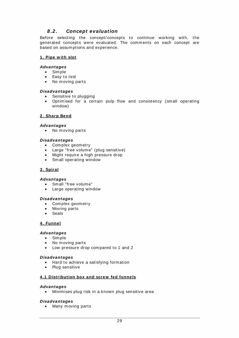
8.2. Concept evaluationBefore selecting the concept/concepts to continue working with, thegenerated concepts were evaluated. The comments on each concept arebased on assumptions and experience.
1. Pipe with slot
AdvantagesSimpleEasy to testNo moving parts
DisadvantagesSensitive to pluggingOptimised for a certain pulp flow and consistency (small operatingwindow)
2. Sharp Bend
AdvantagesNo moving parts
DisadvantagesComplex geometryLarge "free volume" (plug sensitive)Might require a high pressure dropSmall operating window
3. Spiral
AdvantagesSmall "free volume"Large operating window
DisadvantagesComplex geometryMoving partsSeals
4. Funnel
AdvantagesSimpleNo moving partsLow pressure drop compared to 1 and 2
DisadvantagesHard to achieve a satisfying formationPlug sensitive
4.1 Distribution box and screw fed funnels
AdvantagesMinimises plug risk in a known plug sensitive area
DisadvantagesMany moving parts

30
Many motors and sealsFlow control to each funnel
5. Tub
AdvantagesSimpleLow feed pressureNo moving partsLarge opening towards rolls
DisadvantagesPlug sensitive in "non" active volumesLarge volumeBulky
5.1. Tub with screw
AdvantagesLess plug sensitive than 5
DisadvantagesMoving partsSealsSmall opening towards rolls
5.2. Tub with agitator
AdvantagesLess plug sensitive than 5.1 due to more "active" volumeLarge opening towards rolls
DisadvantagesMoving parts
5.3. Tub with agitator and screw
AdvantagesNo obvious advantages compared to 5.2
DisadvantagesMoving partsSeals
5.4. Tub with vibrating device
AdvantagesInnovative idea
DisadvantagesMoving partsLimited effect on "global" formationRisk for material fatigue
Besides listing advantages and disadvantages for the concepts an evaluationmatrix was made (Table 8-1). This matrix is based on the goals/requirements

31
stated in section7. The reference used in the evaluation matrix is thedeltaformer.
Table 8-1. Evaluation matrix.Requirements Weight (1-5) ref. 1 2 3 4 4.1 5 5.1 5.2 5.3 5.4Satisfying formation at +8%pulp consistency.
5 0 -1 0 0 -1 0 1 1 1 1 1
Low feed pressure 5 0 0 0 1 0 1 1 1 1 1 1Reliable/fail safe 2 0 0 0 0 0 -1 1 0 0 0 0Plug sensitivity 4 0 1 0 1 0 1 0 1 1 1 1Handle different productionspeeds
3 0 0 0 1 0 1 1 1 1 1 1
Cost 4 0 1 -1 0 1 0 1 0 0 0 0sum 0 1 -1 3 0 2 5 3 3 3 3"weighted" sum 0 3 -4 12 -1 10 19 17 17 17 17
Based on the results from the concept evaluation it was decided that concept5, 5.1 and 5.2 should be further evaluated and investigated
Concept 5.1 did not involve using a "large" opening in the bottom. Since itwas assumed that the "large" opening is a critical feature for being able toform pulp with high consistency, this concept was modified to a conceptsimilar to 5.2, but with a screw instead of an agitator. It was also assumedinteresting to test how pulp with different consistencies responds tovibrations.

32
9. PrototypeIt was decided to further evaluate the selected concepts by running tests on aprototype. The prototype design phase started with discussions about how asimple, yet representative, prototype should be designed, built and tested.The main goal with the prototype design was to facilitate testing of all theselected concepts.
When tests have been conducted on the paraformer and deltaformer a wiretable, at Metso's Technology Center (TC), have been used to evaluate theformation. The wire table basically consists of a 2.4m wide wire that runsupon perforated plywood boards. The purpose for the perforation is to make itpossible for the pulp to dewater. The wire is powered by a 3.5kW electricmotor equipped with a gearbox (Figure 9-1). The motor is connected to afrequency converter, which makes it possible to alter the speed of the wire.The tests with the Para- and deltaformer has been carried out in the followingway:
Pulp is fed to the formation equipment, from a tank, via a pipe. The outlet ofthe formation equipment is placed so that the pulp "mat" exiting theformation equipment goes onto the wire. The pulp mat then travels to theother edge of the wire table where it falls off into the same tank that feedsthe formation equipment i.e. the pulp circulates. The main reasons for lettingthe pulp mat travel on the wire table is to get a good view of the formation, tomake it possible to take basis weight samples and to see how changes effectsthe formation quality.
It was considered appropriate to use the same wire table when testing thenew prototype. This means that maximum formation width is limited to2400mm (wire width).
Figure 9-1. Wire table
9.1. Design and manufacturingTo save time in this phase of the project the prototype design andmanufacturing was made parallel. The design of the prototype was made inPro/ENGINEER. The prototype was manufactured at TC. The parallel workmeant that decisions regarding the prototype design could be made based theavailable material at TC.
Since concepts 5.1 and 5.2 involved a rotating agitator/screw it was decidedthat an old conveyor screw should be used as starting point for the prototype,see Figure 9-2. This conveyor screw was chosen because it had appropriate

33
dimensions. The length of the screw was approximately 2.4m, which is thesame as the width of the wire on the wire table.
Figure 9-2. Conveyor screw
To easier be able to discuss the design of the formation prototype, asimplified 3D-model of the conveyor screw was made, see Figure 9-3.
Figure 9-3. 3D-model of the conveyor screw.
The model above was used as starting point when the prototype wasdesigned. The finished 3D-model and the actual prototype can be seen inFigure 9-4 and 9-5.

34
Figure 9-4. Finished CAD-model of the prototype.
Figure 9-5. The actual prototype positioned on the wire table.
9.2. FunctionThe prototype design and manufacturing resulted in a prototype that could beused to test and evaluate the selected concepts. During the design andmanufacturing phase a number of new ideas regarding tests that could beperformed with the prototype, were born. To test the ideas a number ofdifferent setups are required e.g. when testing concept 5 the screw has to beremoved. The different setups, and the prototype function for respectively, isdescribed below. Common for all setups is that the wire of the wire table canbe seen as a fictive roll surface in a displacement, TRP press.
In the prototype there are some parts, and features, that are crucial for thefunction. These are marked with a number in Figure 9-6, and the names canbe seen in Table 9-1.

35
Figure 9-6. Important parts for the prototype's function. The prototype is inthis Figure positioned on a section of the wire table.
Table 9-1. Names of important parts.1. Pulp inlet2. Tub3. Lid4. Vertical plate5. Vat6. Feed point7. Screw8. Wire table9. Slot10. Fictive press inlet11. Electric motor12. Gear box
Setup 1: DefaultThis setup is the one shown in the CAD-model above. Pulp is fed to theformation equipment via the pulp inlet (1). The pulp then goes into the tub(2). The pulp level inside the tub creates the feed pressure. The lid (3) andvertical plate (4) forces the pulp to enter the vat (5) through the feed point(6). The reason for feeding the vat through a relatively small opening, at oneend, is to investigate how the formation equipment would function without thetub volume. This setup is equivalent to having a closed vat that is fed withpulp directly from a pipe.
The vertical plate minimises the inlet flow's influence on the flow into the vat.When the pulp enters the vat the screw's (7) rotation transports anddistributes the pulp across the length of the vat (the screw does not havethreads in the Figure). The vat is open in the bottom, the wire of the wire

36
table (8) runs directly under this opening. The pulp exits from the vat througha slot (9) between the wire and the fictive press inlet (10). This slotrepresents the slot between the roll and vat in a displacement TRP press.
The descriptions of the different setups below are all based on setup 1. Thethings that not are mentioned are the same as in setup 1.
Setup 2: No vertical plate (4)Removing the vertical plate should improve the pulp flow into the vat. Onerisk with this setup is that the inlet flow to the tub can effect the flow throughthe feed point.
Setup 3: No vertical plate (4) and fictive press inlet (10)The difference in this setup compared to setup 2 is that the fictive press inletis removed. By doing this the prototype has to form a pulp mat without helpfrom the pressure created by the fictive press inlet. The trials made with thissetup can be compared to the trials with the para- and deltaformer.
Setup 4: No vertical plate (4) and lid (3)In this setup the area between the vat and tub is open. This makes it easierto fill the vat volume with pulp. This Setup is equivalent to concept 5.1, butwith a "large" open area towards the rolls.
Setup 5: Cover plateThis setup is similar to setup 2 but with a plate that covers the wire directlyunder the vat, see Figure 9-7. By mounting this plate it is easier to investigatethe screws ability to form and transport pulp, this because the plate removesthe wire's effect on the formation in the region beneath the screw.
Figure 9-7. Cover plate placement.
Setup 6: No vertical plate (4) and screw (7)With this setup the pulp will have to be transported along the length of thevat without help from the screw.
Setup 7: No vertical plate (4), lid (3) and screw (7)This setup is equivalent to concept 5.
Common for al setups involving the screw is that the rotational direction ofthe screw is according to Figure 9-7. This makes the pulp travel along the

37
back wall of the vat before it lands on the wire, and should decrease the riskfor stagnant pulp beneath the screw.
9.3. Detail descriptions and key dimensionsIn this part of the report detail solutions and key measurements for the maincomponents in the prototype are described. The measurements are takenfrom the actual prototype. Important dimensions that were assumed to havean effect on the formation quality are summarised in the end of this section.
9.3.1. ScrewThe screw's function is to transport and distribute pulp inside the vat. Thescrew's rotational speed can be varied. By having an adjustable rotationalspeed the prototype should become more flexible towards differentproductions and consistencies.
The screw came from the old conveyor screw. No changes were made on thegeometry. The screw's thread dimensions can be seen in Figure 9-8. Thethreads cover the total length of the screw (2400mm).
Figure 9-8. Thread dimensions
The screw is placed in the centre of the circular part of the vat. The clearancebetween the screw and the vat is 5mm. When the prototype is mounted onthe wire table the free distance between the screw and wire is 70mm.
The drive system for the screw consists of a frequency converter, electricmotor, belt drive and gearbox. The motor power is 7.5kW and its rotationspeed is 1430rpm (50Hz). The gearbox has a ratio of 4.17:1. During the trialstwo different combinations of belt pulleys were used:
1. 125mm belt pulley both on the motor and gearbox (gear ratio 1:1)2. 125mm belt pulley on motor, 224 mm on gearbox (gear ratio 1.8:1)

38
The two different combinations of belt pulleys together with the frequencyconverter allowed a variation of screws rotation speed between approximately40-530 rpm.
9.3.2. VatThe vat is also a part from the old conveyor screw. The modification done onthe vat, besides some reparations and removing unnecessary parts, was thatan opening was cut out in the bottom (Figure 9-9).
Figure 9-9. CAD-model of the vat with gables.
The main dimensions of the vat and its opening are as follows:
Vat length: 2400mmVat diameter: 265mmVat height: 300mm
Opening length: 2000mmOpening width: 200mm
The opening is displaced 20mm towards the front of the prototype. Thisdisplacement of the opening was assumed to have a positive effect on theprototype's function. The vat gables are equipped with bearing houses andbearings for the screw.
9.3.3. TubThe pulp level inside the tub is what creates the feed pressure to theequipment. The tub is open in the top, so the feed pressure can never exceeda certain value. The tub is reinforced with flat bars in order to withstand theforces when filled with pulp.
The length of the tub is 2000mm and the height is 1420mm. The bottomopening is 265mm wide and the top opening is 185mm wide. The reason forhaving different opening widths was to get a slope on the tub walls, seeFigure 9-10. The sloping walls should minimize the risk for pulp plugginginside the tub, and makes it easier to feed the vat. The pulp inlet to the tubconsists of a 150mm pipe. The inlet is placed on the same side as the electricmotor, at a height of 475mm (bottom of the tub to the center of the pipe).

39
Figure 9-10. CAD-model of the tub
9.3.4. Fictive press inletThe function of this part, together with the wire, is to simulate the slot insidea displacement wash press.
The mounting holes in this part are designed so that the height of the slot canbe varied between 25-55mm. The length of the fictive press inlet is 1000mm,and the width is 2000mm. In Figure 9-11 it is shown that the top side of thefictive press inlet are reinforced with flat bars. However, the bottom side (theside that faces the wire) has a level surface.
Figure 9-11. CAD-model of the fictive press inlet

40
9.3.5. Summary of important dimensionsThe dimensions that were assumed to have the most influence on theprototype's function are presented below.
Figure 9-12. Important features and dimensions.
The letters below are connected to the corresponding letter in Figure 9-12.
AThe screw body (yellow part) has a length of 2400mm and a diameter of165mm. The threads (red part) on the screw have a height of 45mm and apitch of 120mm. The distance between the screw threads and the wire tableare 70mm.
BWhen the screw is mounted the clearance between the vat and threads are5mm.

41
CThe clearance between the prototype and wire table is 15mm. To prevent pulpfrom leaking out the "wrong" way sealings are mounted in pos. (1) and (2).
DThe vat has a width of 265mm, a height of 300mm and a length of 2400mm.The screw is mounted at the centre of the circular part of the vat. Theopening in the bottom of the vat has a length of 2000mm and a width of200mm. This opening is displaced 20mm towards the front.
EThe slot height between the wire and the fictive press inlet is adjustablebetween 25-55mm. The width of the slot is the same as the opening in thebottom of the vat (2000mm), and the length of the slot is 1000mm
FWhen using setups involving the lid, the feed point opening is 265*265mm.
GThe height of the tub is 1420mm, and the opening in the bottom of the tub is265*2000mm. This means that the opening has the same width as the vatand the same length as the opening in the bottom of the vat. The tub's topopening is 185*2000mm.
42
10. Prototype testing
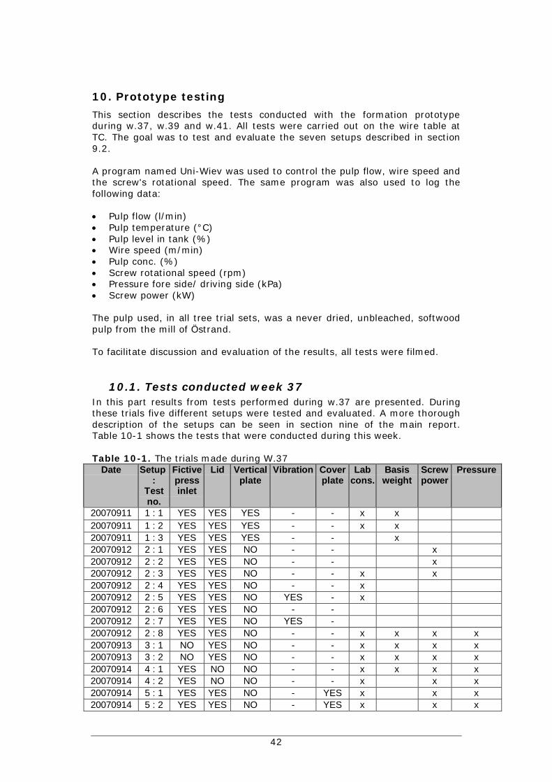
This section describes the tests conducted with the formation prototypeduring w.37, w.39 and w.41. All tests were carried out on the wire table atTC. The goal was to test and evaluate the seven setups described in section9.2.
A program named Uni-Wiev was used to control the pulp flow, wire speed andthe screw's rotational speed. The same program was also used to log thefollowing data:
Pulp flow (l/min)Pulp temperature (°C)Pulp level in tank (%)Wire speed (m/min)Pulp conc. (%)Screw rotational speed (rpm)Pressure fore side/ driving side (kPa)Screw power (kW)
The pulp used, in all tree trial sets, was a never dried, unbleached, softwoodpulp from the mill of Östrand.
To facilitate discussion and evaluation of the results, all tests were filmed.
10.1. Tests conducted week 37In this part results from tests performed during w.37 are presented. Duringthese trials five different setups were tested and evaluated. A more thoroughdescription of the setups can be seen in section nine of the main report.Table 10-1 shows the tests that were conducted during this week.
Table 10-1. The trials made during W.37Date Setup
:Testno.
Fictivepressinlet
Lid Verticalplate
Vibration Coverplate
Labcons.
Basisweight
Screwpower
Pressure
20070911 1 : 1 YES YES YES - - x x20070911 1 : 2 YES YES YES - - x x20070911 1 : 3 YES YES YES - - x20070912 2 : 1 YES YES NO - - x20070912 2 : 2 YES YES NO - - x20070912 2 : 3 YES YES NO - - x x20070912 2 : 4 YES YES NO - - x20070912 2 : 5 YES YES NO YES - x20070912 2 : 6 YES YES NO - -20070912 2 : 7 YES YES NO YES -20070912 2 : 8 YES YES NO - - x x x x20070913 3 : 1 NO YES NO - - x x x x20070913 3 : 2 NO YES NO - - x x x x20070914 4 : 1 YES NO NO - - x x x x20070914 4 : 2 YES NO NO - - x x x20070914 5 : 1 YES YES NO - YES x x x20070914 5 : 2 YES YES NO - YES x x x

43
DateTells which date the test was made
Setup/test no.Setup refers to the setups described in the main report. However thefollowing three columns (Fictive press inlet, Lid, Vertical plate) also tellshow the prototype is equipped during the different trials.
VibrationSince it was predicted that problems feeding the prototype through thefeed point could occur, a vibrating device was built. The idea was thatthat by descending this vibrating device into the feed point opening thepulps ability to flow would be increased.
The vibrating device can be seen in Figure 10-1, and consists of apneumatic external vibrator bolted to a 10*100mm flat bar.
Figure 10-1. Vibrating device
Cover plateTells if the cover plate was mounted.
ConsTells if pulp samples has been taken, and sent to the lab for consistencyanalysis.
Basis weightTells if pulp samples for basis weight analysis has been taken. To eachbasis weight analysis five pulp samples are taken across the width of thepulp mat. These samples are taken at 10, 55, 100, 145 and 190cm, seenfrom the free side of the prototype. The results from these samples canthen be used to plot a curve that represents the basis weight profile of thepulp mat.
Screw powerTells if the power of the electric motor has been measured at the actualtest.
PressureThe pressure is measured with pressure sensors mounted on the back ofthe prototype, see Figure 10-2.

44
Pressure measurementpoints
Pressure measurement points
Figure 10-2. Pressure measurement points
The pressure measurement points are positioned 100mm above the wire,at a distance of 130mm from the vat gables (displaced towards thecentre).
Common for all tests conducted week 37 was that the slot height between thewire and fictive press inlet was set to 40mm. However, the plywood boardthat the wire runs upon was uneven. This caused the slot width to varyaccording to Table 10-2.
Table 10-2. Deviations in slot height. 1= the slot profile where the pulp exitsfrom the fictive press inlet slot. 2 = the slot profile where the pulp enters thefictive press inlet slot.
FS DS0 20 40 60 80 100 120 140 160 180 200 average
1 40 43 44 44 44 44 42 42 43 44 43 432 43 47 49 50 51 52 51 51 50 49 46 49
Table 10-3 summarises the results from w.37. An explanation of the columnscan be found below the table.

45
Table 10-3. Test results from w.37.Setup/
Testno.
Screw(rpm)
Screwpower(kW)
Wirespeed.(m/min)
Q inlet(l/min)
Ratioinlet/outlet
Production(adt/d/m)
PForeside(kPa)
PDriving
side,(kPa)
Sensorconc.
(Cm, %)
Lab conc.(Cm, %)
1 : 1 222 16 2780 2.2 217 5.8 5.31 : 2 294 26 2522 1.2 156 6.2 6.31 : 3 522 32 3087 1.2 229 8.02 : 1 270 1.29 24 3000 1.6 5.02 : 2 435 3.1 26 2800 1.3 8.62 : 3 520 2.81 34 2700 1.0 9.4 7.42 : 4 500 31 2700 1.1 9.4 7.42 : 5 525 28 2200 1.0 >10 7.92 : 6 525 28 2200 1.0 >102 : 7 525 28 2200 1.0 >102 : 8 527 2.54 26 1961 0.9 147 0 0 >10 8.23 : 1 307 2.05 29.5 2380 1.0 168 0 0 8.5 7.73 : 2 334 2.27 22.5 1620 0.9 122 0.4 0 >10 8.44 : 1 200 1.47 30 4050 1.7 358 12 10 8.3 7.44 : 2 160 2.2 20 1800 1.1 0 4.8 >10 8.65 : 1 188 1.08 29 2500 1.1 25 1 6.2 6.15 : 2 357 2.68 24 2550 1.3 7.5 7.8 7.7 7.1
Screw (rpm)The rotational speed of the screw at the time the test was taken.
Wire speed (m/min)The speed of the wire.
Q inlet (l/min)The inlet flow to the prototype
Ratio inlet/outletThis column tells the ratio between the inlet flow and a fictive outlet flow.The fictive outlet flow is calculated the following way:
Qoutlet (m3/min) = slot width (m) * slot height (m) * wire speed (m/min)
(Slot = the slot between the fictive press inlet and the wire)
This gives:
Q outlet = 2 * 0.045 * wire speed
A calculated slot height of 45mm was chosen instead of 40mm. This tocompensate for the deviations caused by the uneven plywood board.
The calculated fictive outlet flow is then converted to the same unit as theinlet flow (l/min). The ratio is finally obtained by dividing the inlet flowwith the fictive outlet flow.
Normally, in a press, this ratio should be above 1 (approximately 1.1-1.2).
Production (adt/d/mformer)The production is calculated based on the basis weight measurements,and wire speed. Inlet flow and pulp concentration can also be used to

46
calculate the production. However, using the basis weight measurementsto calculate the production should, in our case, give more accurate results.
All production values presented from the testing have the unit"adt/d/mformer". To convert these values to "adt/d/m" they have to bemultiplied by 2.
Sensor cons. (Cm, %)The pulp consistency by mass (Cm) is continuously measured with asensor. This sensor is mounted on the pipe that feeds the prototype.
There were quite large differences in the "sensor conc." and "lab conc."values. What this depends on is not clear. It was assumed that the "lab conc."values were more accurate i.e. they were used, as much as possible, whenevaluating the results.
10.1.1. Setup 1This was the first test conducted with the new formation prototype. The goalwas to achieve a "good" formation at as high pulp consistency as possible.During this test we managed to reach a consistency of 8.0% (sensor conc.).The reason we did not reach higher was because the vertical plate made itdifficult to feed the vat.
Figure 10-3 shows the basis weight plots for this setup. Figure 10-4, 10-5 and10-6 are pictures taken just before the corresponding basis weight sampleswas taken i.e. the pictures shows the formation at the actual test.
The lower basis weight deviation in test 3, compared to test 2, is probably aresult of the screw rpm. The higher screw rpm in test 3 resulted in that morepulp was transported towards the driving side.

47
Figure 10-3. Basis weights. Deviation test 1 = 18 %, test 2 = 30%, test 3 =14%.
Figure 10-4. 1 : 1
Figure 10-5. 1 : 2
0
500
1000
1500
2000
2500
3000
3500
4000
4500
0 20 40 60 80 100 120 140 160 180 200
Width, cm
Bas
isw
eigh
t, g/
m²
1 : 1
1 : 2
1 : 3

48
Figure 10-6. 1 : 3
10.1.2. Setup 2To facilitate the feeding of the vat, the vertical plate was removed. Thischange made it possible to reach a consistency of 8.2% (lab cons.) The basisweight profile at this consistency can be seen in Figure 10-7. Figure 10-8shows a picture of the formation at the test occasion.
In test no. 5 and 7 the vibrating device was used. However, the vibrations didnot improve the feeding of the vat noticeable.
0
500
1000
1500
2000
2500
3000
3500
4000
4500
0 20 40 60 80 100 120 140 160 180 200
Width, cm
Bas
isw
eigh
t, g/
m²
2 : 8
Figure 10-7. Basis weight for setup 2, Approximately 30% deviation.

49
Figure 10-8. 2 : 8
10.1.3. Setup 3The goal with this test was to see how the prototype behaved without thefictive press inlet. The prototype had problems forming an even mat at pulpconsistencies below 5%. However, at higher consistencies the pulp mat basisweight profile became more even. One observation during these trials wasthat the structure of the pulp mat was coarser compared to the testconducted with the fictive press inlet mounted. This can be seen in Figure 10-10 and 10-11. Figure 10-9 shows the results from the basis weight samples.
0
500
1000
1500
2000
2500
3000
3500
4000
4500
5000
0 20 40 60 80 100 120 140 160 180 200
Width, cm
Bas
isw
eigh
t, g/
m²
3 : 1
3 : 2
Figure 10-9. Basis weights for setup 3, deviation test 1 = 27%, test 2 =50%

50
Figure 10-10. 3 : 1
Figure 10-11. 3 : 2
10.1.4. Setup 4With this setup the formation became more sensitive to the rotational speedof the screw. The screw "pushes" the pulp against the driving side gable ofthe tub. This makes it difficult to keep an even pulp level in the tank i.e.makes it hard to achieve an even formation. Removing the screw'stransportation abilities could solve this problem.
Capacity limiting in this set up was the wire speed and inlet flow. At test 2 thewire speed is 20m/min (lowest possible) and the inlet flow 1800l/min (highestpossible). This was not enough to keep the whole width of the vat filled withpulp. Figure 10-14 shows a picture of the formation at test no. 2. In thepicture it can be seen that the basis weight is significantly lower towards thefree side.
Figure 10-12 and 10-13 shows the basis weight, and formation, for test no.1.Here it can also be seen that the basis weight is somewhat higher towards thedriving side.

51
Figure 10-13. 4 : 1
Figure 10-14. 4 : 2
0
1000
2000
3000
4000
5000
6000
0 20 40 60 80 100 120 140 160 180 200Width, cm
Bas
isw
eigh
t, g/
m²
4 : 1
Figure 10-12. Basis weight profile for test no 1. Deviation = 37%

52
10.1.5. Setup 5No basis weight samples was taken when testing this setup. However, withthis setup the screw had a more significant influence on the formation,compared to the tests with setup 1, 2 and 3. It was difficult to find anappropriate combination of inlet flow, screw rpm and wire speed. In Figure10-15 and 10-16 pictures of the formation at test no 1 and 2 can be seen. Atapproximately 7% the screw stopped (probably due to overload).
Figure 10-15. 5 : 1
Figure 10-16. 5 : 2

53
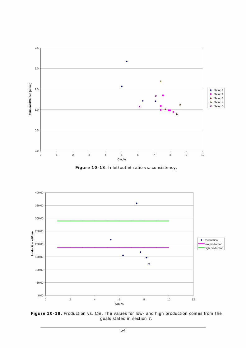
10.1.6. DiscussionThe overall the test results from week 37 was satisfying. The new prototypehad potential to achieve the goals. During the tests the maximum feedpressure was approximately 15kPa, which is less than the goal stated in themain report (50kPa). The goal, to be able to feed the equipment with 12%pulp consistency, is not yet reached. This partly depends on limitations in thesurrounding systems (pump capacity and wire speed). At high conc. the pumpdid not mange to deliver the decried flow rate, which resulted in a lowproduction, see Figure 10-19. The lowest possible wire speed was 20m/min.This in combination with the feeding problems made it difficult to keep asatisfying inlet/outlet ratio when feeding the prototype with high consistencypulp. In Figure 10-18 the inlet/outlet ratio is plotted against pulp consistency.
The uneven plywood board beneath the prototype should be replaced beforerunning more tests.
To make facilitate feeding the vat the guide bars for the vertical plate shouldbe removed. These guide bars can be seen in Figure 10-17.
G uide bars
Figure 10-17. Guide bars
54
0.00
50.00
100.00
150.00
200.00
250.00
300.00
350.00
400.00
0 2 4 6 8 10 12Cm, %
Prod
uctio
n ad
t/d/m
Productionlow productionhigh production
0.0
0.5
1.0
1.5
2.0
2.5
0 1 2 3 4 5 6 7 8 9 10Cm, %
Rat
io in
let/O
utle
t, [m
³/m³]
Setup 1Setup 2Setup 3Setup 4Setup 5
Figure 10-19. Production vs. Cm. The values for low- and high production comes from thegoals stated in section 7.
Figure 10-18. Inlet/outlet ratio vs. consistency.

55
10.2. Tests conducted week 39This part of the report presents the tests conducted week 39. Changes on theequipment compared to w.37 were:
A new plywood board was mounted.The guide bars for the vertical plate was removed.
One of the goals for this week was to test how the prototype behaves withoutthe screw. We also wanted to verify the tests conducted with the screw duringw.37.
The tests were conducted in the same way as the tests w.37, and are listed inTable 10-4. An explanation to the different columns can be found in section10.1.
Table 10-4. Tests w.39
Date Setup:Test no.
Fictivepressinlet
Lid Screw Cons Basisweight
Screwpower Pressure
2007-09-25 6:1 YES YES NO X2007-09-25 6:2 YES YES NO X X X2007-09-25 6:3 YES YES NO X X X2007-09-25 6:4 YES YES NO X X2007-09-25 7:1 YES NO NO X X X2007-09-25 7:2 YES NO NO X X X2007-09-27 2:1 YES YES YES X X X2007-09-27 4:1 YES NO YES X X X2007-09-27 4:2 YES NO YES X X2007-09-27 4:3 YES NO YES X X2007-09-27 4:4 YES NO YES X X
As seen in the table above no screw power measurements was recorded week39. The slot height between the fictive press inlet and wire was set to 40 mm.
The results from week 39's testing can be seen in Table 10-5. One differencebetween week 39 compared to week37, is that consistency samples weretaken from both the inlet pipe and the tub. This should make it easier toevaluate which consistency measurement that is the most accurate.

56
Table 10-5. Results from w.39
Setup:Test no.
Wirespeed.(m/min)
Screw(rpm)
Ratioinlet/outlet
Productionadt/d/m
P foreside,kPa
P Driveside,kPa
Pulpkonc.signal
(%)
Labconc.Pipe(%)
Labconc.Tub(%)
6:1 32 - 1.4 - 4.2 0.4 4.1 - -6:2 32 - 1.3 144 12.3 0.8 4.6 4 -6:3 35.5 - 0.9 169 14.4 0 7.2 6.6 7.66:4 36.7 - 0.8 - 9.8 0 8.1 7.2 7.67:1 35.4 - 1.2 258 31.4 9.8 8 7.4 7.57:2 30.8 - 1.1 222 11.6 5.1 9.3 8.3 8.42:1 36 376 1.0 191 0 5.6 8.1 7.4 8.44:1 27 166 1.1 180 0 9.3 9.1 8.2 8.74:2 23 140 0.9 - 0 6.5 >10 8.9 10.24:3 20 99 0.9 - 0 4.2 >10 9.7 10.94:4 20 67 0.9 - 0 0.35 >10 11.1
10.2.1. Setup 6When testing this setup the pulp has to be transported across the width of thevat without help from the screw. At consistencies around 4% there were noproblems forming a relatively even pulp mat. As the consistency increased itbecame more difficult to transport the pulp across the width of the vat. Thiscan also be seen in the basis weight plot, and the pictures of the formation(Figure 10-20, 10-21 and 10-22). Figure 10-23 shows a picture of theformation at test no. 4, where the problem to distribute the pulp across thewidth can be seen.
Figure 10-20. Basis weights for setup 6. Deviation test 2 = 16%, test 3 = 70%
0
500
1000
1500
2000
2500
3000
3500
4000
0 20 40 60 80 100 120 140 160 180 200Width, [cm]
Bas
isw
eigh
t, g/
m²
6 : 2
6 : 3

57
Figure 10-21. 6 : 2
Figure 10-22. 6 : 3
Figure 10-23. 6 : 4

58
When disassembling the prototype it could be noticed that stagnant pulp hadbeen gathered directly below the lid, see Figure 10-24. This indicates thatonly the pulp closest to the wire is active (flows) with this set up.
Figure 10-24. Stagnant zone of pulp beneath the lid
10.2.2. Setup 7The basis weight profile, when testing this setup, had a relatively lowdeviation (Figure 10-25, 10-26 and 10-27). The placement of the pulp inletcauses variation of the pulp level in the tub i.e. the pulp level becomes higherat the side where the inlet is placed. The difference between the pulp level atthe driving and fore side was approximately 0.5m. This means that thepressure should be approximately 5kPa higher at the driving side. However,no significant effect of this pressure/height difference can be seen in the basisweight plot. This indicates that it is not critical for the formation to have theexact same pressure inside the whole vat.
Setup 7 was not completely tested due to a breakdown of a component in thepulp tank.

59
Figure 10-26. 7 : 1
Figure 10-27. 7 : 2
Figure 10-25. Basis weights for setup 7. Deviation test 1 = 18%, test no. 2 =10%
0
1000
2000
3000
4000
5000
6000
0 20 40 60 80 100 120 140 160 180 200Width, [cm]
Bas
isw
eigh
t, g/
m²
07:01
07:02

60
10.2.3. Setup 2In this trial the goal was to verify the results for setup 2 from w.37. Adifferent behaviour of the prototype, compared to the same test w.37, wasnoticed. The rotational speed of the screw had to be set lower in order to geta satisfying pulp distribution, and the screw stopped a number of times due tooverload. These two things were probably connected. The lower screw rpm ledto a higher load on the electric motor, which caused it to stop.
One basis weight sample was taken with this setup (Figure 10-28 and 10-29).As seen in the Figure, and picture, the basis weight is higher towards thedriving side. This is probably a result of that the screw rpm was to high.However, it was not an option to lower the rpm, cause then the screw wouldstop.
Figure 10-29. 2 : 1
02:01
0
500
1000
1500
2000
2500
3000
3500
4000
4500
0 20 40 60 80 100 120 140 160 180 200Width, [cm]
Bas
isw
eigh
t, g/
m²
02:01
Figure 10-28. Basis weight for setup 2. Deviation = 60%

61
10.2.4. Setup 4With setup 4 the so far highest pulp consistency was reached (11.1%). Thereason no higher consistency was reached was because the screw stopped.There were still problems with the wire speed and inlet flow, which made itdifficult to get an even formation at the higher consistencies, see Figure 10-32.
In Figure 10-30 and 10-31 the basis weight profile for test no 2 can be seen.The basis weight is somewhat higher towards the driving side, which was alsoobserved during the corresponding test w.37.
Figure 10-31. 4 : 2
04:02
0
1000
2000
3000
4000
5000
6000
0 20 40 60 80 100 120 140 160 180 200Width, [cm]
Bas
isw
eigh
t, g/
m²
04:02
Figure 10-30. Basis weight setup 4. Deviation = 43%

62
Figure 10-32. 4 : 4
10.2.5. DiscussionOne interesting thing observed during these tests was that the basis weightdeviations from the tests conducted with setup 7 was low. Unfortunately itwas not possible to test the limit for how high consistency this setup couldhandle (breakdown of agitator in pulp tank).
For some reason the verifying results differed somewhat between w.37 andw.39. When testing setup 2 the rotational speed of the screw had to be lower,compared to w 37, to get an even distribution of the pulp. The new plywoodboard had fewer holes directly beneath the screw. This decreases thedewatering possibilities for the pulp, which could lead to that the wire doesnot get the same "grip" on the pulp. Less grip means that a higher pressure isneeded for the pulp to exit the vat i.e. the screw rpm has to be kept lower toget an even pressure inside the vat. One other thing that can have influencedthe screw rpm is that the fictive press inlet slot became somewhat narrower(40mm) when the plywood board was changed. The narrower slot results inthat less pulp has to be transported across the length of the vat i.e. the screwrpm has to be lower.
The hole pattern in the plywood board should be modified to match the holepattern in the old board. This way the effect of the dewatering possibility canbe investigated.
The measured pulp consistency from the tub seems to agree more with thepulp cons. signal obtained from the sensor. However, it is hard to say whichmeasurement that is the most accurate.
There were still the same problems with the surrounding equipment i.e.problems to keep a satisfying inlet/outlet ratio, and production, at the higherconsistencies, see Figure 10-33 and 10-34.

63
0
50
100
150
200
250
300
350
0 2 4 6 8 10 12Cm, %
Prod
uctio
n ad
t/d/m
Productionhigh productionlow production
0.0
0.2
0.4
0.6
0.8
1.0
1.2
1.4
0 2 4 6 8 10 12
Cm (%)
Rat
io in
let/O
utle
t, [m
³/m³]
i
Setup 6Setup 7Setup 2Setup 4
Figure 10-34. Production vs. consistency
Figure 10-33. Inlet/outlet ratio vs. Cm

64
10.3. Tests conducted week 41For week 41, the hole pattern in the plywood board was modified (more holesbeneath the vat). This modification should show how important thedewatering possibility is for the function of the prototype.
The goals for these trials were to se how setup 2 responds to the improvedhole pattern, and to fully evaluate setup 7. In Table 10-6, the measurementsconducted week 41 are listed.
Table 10-6. Tests conducted w.41.
Date
Set up:Testno.
Pulpthickness
(mm)
Fictivepress hod Lid Screw Cons Basis
weightScrewpower
Pressure
2007-10-08 2:1 40 YES YES YES x x x x2007-10-08 2:2 40 YES YES YES x - x x2007-10-08 2:3 40 YES YES YES x - x x2007-10-08 2:4 40 YES YES YES - - - x2007-10-08 2:5 40 YES YES YES x x x x2007-10-10 7:1 40 YES NO NO x x - x2007-10-10 7:2 40 YES NO NO x x - x2007-10-10 7:3 25 YES NO NO x - - x2007-10-10 7:4 25 YES NO NO x - - x
Table 10-7 summarises the results from w.41. Due to technical problems nosignal from the pulp cons. sensor was logged.
Table 10-7. Results from w.41.
Setup:
Testno.
Wirespeed.(m/min
)
Q(l/min
)
Screw
(rpm)
Pulpkonc.signal (%)
Pulpthickness (mm)
Screwpower(kW)
Ratioinlet/outlet
m³/m³
Productio
nadt/d/
m
Pfreeside,kPa
PDriveside,kPa
Labconc.Pipe
Labconc
.Container
2:1 33 2350 ? 40 7 0.9 172 0 2 7.7 72:2 32 1850 454 ? 40 6 0.7 0 0 8.1 8.32:3 34 1700 650 ? 40 6.1 0.6 8.7 8.12:4 24 1380 429 ? 40 0.72:5 20 1050 392 ? 40 6.5 0.7 88 0 3 9 8.47:1 34 3150 ? 40 1.2 239 0 0 8.8 8.97:2 20 1120 ? 40 0.7 140 0 3.5 10.2 10.87:3 34 1680 ? 30 1.6 0 2 10.6 11.77:4 30 1680 ? 30 1.9 1 8 10.1 10.9
10.3.1. Setup 2The modified hole pattern made it easier to control the formation. The screwrpm could be held at a higher level compared to the tests w.39. The higherrotation speed made the screw less sensitive to overload, and increased therunnability for the setup. A pulp consistency of approximately 8.5–9% wasreached, which is comparable with the results from w.37. The basis weightprofile for test no. 1 and 5 can be seen in Figure 10-35, 10-36 and 10-37.With this setup there are problems to feed the vat at consistencies above 8%.This causes problems to keep a satisfying inlet/outlet ratio.

65
Figure 10-36. 2 : 1
Figure 10-37. 2 : 5
0.0
500.0
1000.0
1500.0
2000.0
2500.0
3000.0
3500.0
4000.0
0 20 40 60 80 100 120 140 160 180 200Width, [cm]
Bas
is w
eigh
t,[g/
m²]
02:0102:05
Figure 10-35. Basis weights. Deviation test 1 = 28%, test 2 = 68%

66
10.3.2. Setup 7The goal for this run was to test how high consistency this setup could handle.To be able to keep higher inlet/outlet ratio the slot height was decreased to30mm at test no. 4. With this slot height the prototype managed to formpulp with a consistency of 10.6-11.7%. The formation at test no.4 can beseen in Figure 10-38. It was difficult to start the formation after a stop. Thisbecause the pulp inside the vat tended to "hang" above the wire i.e. the wiredid not get grip on the pulp. However, when the formation started this wasnot a problem. This indicates that it is important that the pulp continuouslymoves inside the vat/tub.
Figure 10-39, 10-40 and 10-41 shows the formation for test no. 1 and 2. Thebasis weight deviations for this setup is generally low.
Figure 10-38. 7 : 4
0.0
500.0
1000.0
1500.0
2000.0
2500.0
3000.0
3500.0
4000.0
4500.0
5000.0
0 20 40 60 80 100 120 140 160 180 200Width, [cm]
Bas
is w
eigh
t,[g/
m²]
07:0107:02
Figure 10-39. Basis weights. Deviation test 1 = 17%, test 2 = 18%

67
Figure 10-40. 7 : 1
Figure 10-41. 7 : 2
10.3.3. DiscussionBy doing new tests on setup 2 it could be established that the dewateringpossibilities has an effect on the formation. To make the testing as realistic aspossible the dewatering possibilities for the wire table should be the same asin a press (19% open area).
When testing setup 2 there were problems to feed the vat at consistenciesabove approximately 8%. One thing that can solve this problem is to removethe tub and feed pulp directly into the vat (pressurise the vat).
Setup 7 gives the lowest basis weight deviations of all setups. The problem tostart the formation after a stop is assumed to depend on the shape of the vat.The widest part of the vat is 265mm, and the opening in the bottom of thevat is 200mm. This narrowing causes the pulp to "hang". If the prototypewould have a constantly increasing cross section area towards the wire, thiswould probably not be a problem.
The pulp used in these trials was quite worn. However, it is difficult to sayhow much that effects the results.
The accuracy of the values obtained from the different sensors is not known.We can see that there are some differences in the consistency measurements.Which consistency measurement (pipe, tub or sensor) that is the mostaccurate is difficult to say. However, the manual measurements (pipe, tub)should give the most accurate result.

68
11. Vibration testsLab tests were conducted to get an idea of how pulp suspensions withdifferent consistencies responds to vibrations. The full report from these testscan be found in appendix 2. The vibration source used was an electric pokervibrator. Four different consistencies were tested (3, 5, 7 and 9%).
The conclusions made from this trial were:
Vibrations increases the pulp suspension's ability to flow i.e. vibrations canto some extent break the fiber network.
The effect of the vibrations decreases quite rapidly as the distance to thevibration source increases.
Based on these tests it is difficult to say if, and how, a vibrating device canbe used in a formation equipment.

69
12. Discussion and conclusionsOverall, the results from the testing were satisfying. We managed to form a2m wide pulp mat at a consistency of approximately 11-12%, and with amaximum feed pressure of 15kPa. However, more testing, evaluation anddiscussion is needed before a final concept can be selected.
Discussing the results, limitations and prototype design led to the conclusionthat the following three concepts/setups has the highest potential:
Setup 2Because of limitations in wire speed, inlet flow, problems with overloading thescrew etc. this setup was difficult to test as planed. Therefore the resultsobtained with this setup was not always satisfying. However, Feeding the vatwith pulp at one end, and then transporting it towards the other end with helpfrom pressure and a rotating device is an interesting solution from a designpoint of view. If this concept were to be further developed it has potential toresult in relatively small formation equipment.
Setup 4The design of the prototype was not optimal for testing this setup. The screwtransports the pulp towards the same side where the pulp inlet is placed. Thiscauses problems to distribute the pulp across the whole width. If the screwstransporting abilities were to be removed (replacing the screw with anagitator) the results from the tests with this setup would probably besignificantly improved.
Setup 7With this setup we reached the highest consistency, and also the lowestdeviations in pulp mat basis weight. One advantage with this setup is that itdoes not involve any moving parts (except for the wire). However, the factthat there is no moving part to help the pulp stay floating means that there isa higher risk for pulp plugging. This was not a problem during the relativelyshort test sessions performed at the lab. But it could become a problemduring full-scale operation, where the formation equipment will have tofunction for a long period of time without maintenance.
The guidelines for this project have been the goals stated in section 7. In thelist below each goal is commented based on the knowledge gained during thework with this project.
12% pulp consistencyThe testing has shown that it is possible to form pulp with consistencies upto 12%.
Max 50kPa pressure dropDuring the prototype testing we had a maximum feed pressure of 15kPa.For some of the setups this was sufficient, and for some a higher pressurewould be preferred. However, 50kPa still seems like a realistic goal for afull-scale prototype.
Less than 20% deviation in mat basis weightUnder the right circumstances this goal should not be a problem. Whentesting the prototype the basis weight deviation was low as long as the vatvolume was evenly filled with pulp.

70
Operate for a minimum of 12 months without maintenanceThis is something that is difficult to evaluate at the lab. The geometry of afull-scale prototype will have to be designed so that the risk for plugging isminimised.
Designed to fit 1572 TRP G5Simpler studies on how the G5 can be equipped with a new formationequipment has been made. These studies show that it probably will bepossible, but it might be necessary to redesign some of the parts in thepress.
Capable of handling production speeds from 370-580 adt/d/m(1572 press)The lab trails showed that the formation was satisfying as long as the vatvolume was evenly filled with pulp. Different production speeds should noteffect the formation as long as this criterion is fulfilled.
Cost less than 2 million sek.This is something that is difficult to evaluate based on what is knowntoday. However, nothing indicates that a new formation equipment shouldbecome more expensive than today's systems.

71
13. Future workThe surrounding equipment (feed screw in tank, pump, wire and agitator intank) was not designed to handle the consistencies/flows needed to test theprototype. This lead to that the prototype, in some cases, could not be testedas planed. To further evaluate the selected concepts the performance of thesurrounding equipment has to be improved. Therefore, the feed screw, thatfeeds the pump, will be upgraded. This modification will hopefully make itpossible to feed the prototype with the desired flow rate at the higherconsistencies (>10%). The plywood board below the prototype is beingreplaced with the same type of perforated steel plates that are used on theroll surfaces in a press. This will hopefully result in more realistic dewateringpossibilities.
The prototype is being modified so that it will be possible to pressurise thevat. Feeding the vat at a higher pressure will hopefully give a better view ofhow the concepts would function during full-scale operation.
If a new formation equipment is to be developed, more useful informationcould be gathered by first running tests on the 1508 TRPB press in the lab.Since the press is only 800mm wide it will probably not be possible toevaluate the formation. But it can still give useful information on how theperformance of a press is effected if it is fed with pulp consistencies above10%.


Appendix 1
Brainstorming compendium

Paraformer/Deltaformer

Brainstorming 05-09-29


1. Strippa dagens lösning på instrument (Liknande DPB)2. Ta bort enbart flödesmätningen och behålla ventilerna3. Ta bort ventilerna och behålla flödesmätningen
4. Byxrörsfördelning
5. Volymetrisk pump (Kugg) till varje inlopp moterad på samma axel6. Volymetrisk pump (Kugg) över hela längden ersätter Delta/Paraform
7a. Inloppslåda direkt på Deltaformerns undersida7b. 7a utrustad med horisontell separat "pirra" vid varje inlopp7c. 7a utrustad med horisontell gemensam "pirra" genom hela lådan7d. 7a utrustad med vertikal separat "pirra" vid varje inlopp7e. 7a utrustad med vertikal separat "liten skruv" vid varje inlopp
Syftet med pirror och skruvar är primärt att förhindra pluggning.Fördelningen måste I alla fallen utom I skruvfallet ske genom tryckfall.I skruvfallet kan man tänka sig att dessa fungerar som pumpar även om mötet såg problemen meddetta. En ide fanns också att en skruv bara snurrar med av flödet.
Centralt inlopp är att föredra jmf med att mata I en ende på inloppsrör av flera orsaker symmetri är enoch därmed är Hö/Vä variant ej aktuellt som vi tidigare brottats med på Tex DPB. Ur plant designsynvinkel är detta egalt men har stor påverkan på Designvarianter.
Ide nr. 7 kan införas idag då den innebär små maskinmässiga förändringar.Pluggningsdiskussionen bör utredas vidare med Laborationer. Rickard tar tag I detta.
Ide nr 5, Peter D undersöker vad som finns på marknaden vad gäller volymetriska pumpar som passarför applikationen/ kostnad. Kugghjulspumpar lider av slitageproblem och höga UH kostnader vilket ärden stora nackdelen och förmodligen helt avgörande.
Marknadsmässigt kommer en ren 7a lösning att bli svår att argumentera för med tanke på historien medpluggade inloppslådor och strypningar. Kvaerner kommer också att som vanligt göra sitt jobb när detgäller att "sabla" ner denna lösning, tala om för kunderna hur "dumma" vi är och argumentera för sinskruv som troligen håller strypningen öppen och hjälper till att fördela.
Något mer måste till som medger okänslighet för olika driftfall som kan uppstå. Därav de andra 7b-eideerna. Det är också viktigt att tänka på att det inte får bli "smäck" och pillrigt då det ärFabriksapplikation vi talar om. Driftsäkerhet och så långt som möjligt reducera behovet av UH ärmycket viktiga aspekter på detta.
Ide 7d-e har fördelar såtillvida att det medger omrörning genom genomföringen/strypbrickan.
Med lösning 7 (fördelning med statisk strypning) är vi definitivt tillbaka med kravet på braflödesstyrning och ett snävare flödesintervall för att kunna garantera en bra funktion.

Brainstorming 05-12-05

1) Massafördelning med direktpåläggning av massa nära valsen. Helt ny formeringsprincip för Metsosom kräver omfattande tester på lab m.m.
2) Fördelning som bygger på samma princip som BGA-mixern. Fördelningsrör som konar frånfyrkantigt till runt tvärsnitt.
3) Uppblåsbar slang inuti ledningen som stryper och släpper igenom flöde beroende påuppblåsningsgrad. Materialproblem med gummi i kontakt med massasuspensionen.
4) Roterande slussmatare som portionerar ut massa till ett antal inlopp. Problem med tryckspikar?Hinner man fylla och tömma facken? Helt ny fördelningsprincip som kräver omfattande utredningaroch tester.
5) Integrera flödesmätare och ventiler på pressen. Ger en kostnadsbesparing om vi kan finna billigareflödesmätare och ventiler än de som används i projekten.
Mötet ansåg att idé nr 5 var en framkomlig väg. Finns det billigare alternativ på flödesmätare ochventiler? Kommer kunderna att acceptera den utrustning vi skickar med pressen med tanke på att det ivissa fall kommer att innebära avsteg från fabriksstandard? ACTION: Johan B utreder dessa frågormed Automation, Plant Design, Marknad och Projekt.

Konkurrenter
GL&V (Kvaerner)
Andritz

Formering på andra ställen
Asfaltsläggare:
1= asfaltsbehållare2= transportband3= skruv4= utjämnare

Pappersmaskin:
Head boxHead box
Distribution boxes

Panelboard (MDF)

Panelboard (masonit)


Appendix 2
Vibration tests

IntroductionOne idea in the concept generation phase involved a vibrating device. Since theknowledge about how pulp of different consistencies responds to vibrations it limited,it was decided that a simple "vibration test" should be performed.
Method and resultsThe vibration source used in these trials was an electric powered poker vibrator(figure 1).
Figure 1. Vibration source.
The effect of the poker vibrator was 600W, and it had a maximum rotation speed of3300rpm (3300Hz). The amplitude of the vibration is unknown.
To be able to evaluate the effect of the vibration, two 10-liter buckets with holes inthe bottom were prepared, see figure 2. The diameter of the holes was 40 and 80mm.The reason for having different diameter holes in the buckets was to make it possibleto test pulp with different consistencies (high consistency pulp might have problemsflowing through the hole with smaller diameter). The time it took for the pulp to sinkto a certain level, with and without vibration, was measured. By comparing theseresults, the effect of the vibration on the pulp suspension could be evaluated.

Figure 2. The two buckets used in the trials.
The pulp suspension used in the trials was a never dried, unbleached, Scandinaviansoftwood kraft pulp from the mill of Östrand. The pulp consistencies used in the trialswere approximately 3, 5, 7 and 9%.
The results obtained from the trials can be seen in table 1. The "Outlet Cm" columnindirectly tells if water has separated from the pulp suspension during the trial e.g. intest no. 4 there is a Cm difference of approximately 2%. In the "Vibration" column"center" means that the vibration stick was positioned in the center of the outlet hole,"corner" means that the vibration stick was positioned as far away as possible fromthe outlet hole.
Table 1. Test results
Test no. Cm % Hole dia.mm
Vibration Flow rateapprox. l/s
Outlet Cmapprox. %
1 3 80 No 7 32 3 40 No 2 33 5 40 No 0 04 5 40 Yes (corner) 0.1 35 7 80 No 0 06 7 80 Yes (corner) 0.3 67 7 80 Yes (center) 0.35 68 9 80 No 0 09 9 80 Yes (center) 0.2 8
Discussion/ConclusionsBy studying the results it can clearly be established that vibrations has an effect on thepulp suspensions ability to flow. E.g. in test no. 5 the flow rate became 0l/s, the samesetup but with vibrations added to the pulp suspension (test no. 6) resulted in a flowrate of 0.3l/s.
The position of the vibration stick in the bucket had an influence on the flow rate.This indicates that the effect of the vibrations decreases quite rapidly as the distanceto the vibration source increases.
Based on these tests, it is difficult to state if, and how, a vibrating device shall be usedin a formation equipment.