Embed Size (px)
Citation preview


©2003 Dynojet Research, Inc. All Rights Reserved.
Installation Guide For Model 200i and 250i Motorcycle Dynamometers.
This manual is copyrighted by Dynojet Research, Inc., hereafter referred to as Dynojet, and all rights are reserved. This manual is furnished under license and may only be used or copied in accordance with the terms of such license. This manual is furnished for informational use only, is subject to change without notice, and should not be construed as a commitment by Dynojet. Dynojet assumes no responsibility or liability for any error or inaccuracies that may appear in this manual. Except as permitted by such license, no part of this manual may be reproduced, stored in a retrieval system, or transmitted, in any form or by any means, electronic, mechanical, recording, or otherwise, without the prior written permission of Dynojet.
The Dynojet logo is a trademark of Dynojet Research, Inc.
Any trademarks, trade names, service marks, or service names owned or registered by any other company and used in this guide are the property of their respective companies.
Dynojet Research, Inc., 2191 Mendenhall Drive, North Las Vegas, Nevada 89031, USA.
Printed in USA.
Part Number: 98220104 Version 2 (05/03)

Model 200i and 250i Motorcycle Dynamometer Installation Guidei
TABLE OF CONTENTS
Warnings . . . . . . . . . . . . . . . . . . . . . . . . . . . . . . . . . . . . . . . . . . . . . . . . v
Chapter 1 Specifications and Operating RequirementsIntroduction . . . . . . . . . . . . . . . . . . . . . . . . . . . . . . . . . . . . . . . . . . . . . . . . . .1-2
Conventions Used In This Manual . . . . . . . . . . . . . . . . . . . . . . . . . . . . . . . 1-3Technical Support . . . . . . . . . . . . . . . . . . . . . . . . . . . . . . . . . . . . . . . . . . . 1-3Your Dyno Room . . . . . . . . . . . . . . . . . . . . . . . . . . . . . . . . . . . . . . . . . . . .1-3
Dynamometer Specifications . . . . . . . . . . . . . . . . . . . . . . . . . . . . . . . . . . . . 1-5Chassis Specifications . . . . . . . . . . . . . . . . . . . . . . . . . . . . . . . . . . . . . . . . .1-5Electrical Requirements . . . . . . . . . . . . . . . . . . . . . . . . . . . . . . . . . . . . . . . 1-7Environmental Requirements . . . . . . . . . . . . . . . . . . . . . . . . . . . . . . . . . . . 1-7Shop Air Requirements . . . . . . . . . . . . . . . . . . . . . . . . . . . . . . . . . . . . . . . 1-7
Power Requirements and Installation . . . . . . . . . . . . . . . . . . . . . . . . . . . . . 1-8Installing the Wall Receptacle . . . . . . . . . . . . . . . . . . . . . . . . . . . . . . . . . . . 1-8Testing for Correct Voltages . . . . . . . . . . . . . . . . . . . . . . . . . . . . . . . . . . . . 1-9Connecting the Dyno . . . . . . . . . . . . . . . . . . . . . . . . . . . . . . . . . . . . . . . . 1-9
Other Requirements . . . . . . . . . . . . . . . . . . . . . . . . . . . . . . . . . . . . . . . . . .1-1012 Volt Battery . . . . . . . . . . . . . . . . . . . . . . . . . . . . . . . . . . . . . . . . . . . . .1-10Computer Specifications . . . . . . . . . . . . . . . . . . . . . . . . . . . . . . . . . . . . .1-10Motorcycle Tie-Down Straps . . . . . . . . . . . . . . . . . . . . . . . . . . . . . . . . . .1-10Phone and Internet Access . . . . . . . . . . . . . . . . . . . . . . . . . . . . . . . . . . . .1-10
Model 200i Motorcycle Dynamometer . . . . . . . . . . . . . . . . . . . . . . . . . . .1-11Model 250i Motorcycle Dynamometer . . . . . . . . . . . . . . . . . . . . . . . . . . .1-12

Model 200i and 250i Motorcycle Dynamometer Installation Guide
T A B L E O F C O N T E N T S
ii
Chapter 2 InstallationUnpacking and Inspecting the Dyno . . . . . . . . . . . . . . . . . . . . . . . . . . . . . .2-2
Routing the Computer, Pendant, and Starter Cables . . . . . . . . . . . . . . . . . 2-6Installing the Theta Controller . . . . . . . . . . . . . . . . . . . . . . . . . . . . . . . . . . 2-7Installing the Tire Carriage . . . . . . . . . . . . . . . . . . . . . . . . . . . . . . . . . . . . . 2-8Removing the Dyno from the Crate . . . . . . . . . . . . . . . . . . . . . . . . . . . . .2-12
Pickup Card . . . . . . . . . . . . . . . . . . . . . . . . . . . . . . . . . . . . . . . . . . . . . . . . .2-14Battery . . . . . . . . . . . . . . . . . . . . . . . . . . . . . . . . . . . . . . . . . . . . . . . . . . . . .2-15Replace the Drum Side and Top Covers . . . . . . . . . . . . . . . . . . . . . . . . . .2-16Ramp Bracket . . . . . . . . . . . . . . . . . . . . . . . . . . . . . . . . . . . . . . . . . . . . . . . .2-18Ground Hooks . . . . . . . . . . . . . . . . . . . . . . . . . . . . . . . . . . . . . . . . . . . . . . .2-21
Chapter 3 Dyno ElectronicsDyno Electronics . . . . . . . . . . . . . . . . . . . . . . . . . . . . . . . . . . . . . . . . . . . . . . 3-2
Atmospheric Sensing Module . . . . . . . . . . . . . . . . . . . . . . . . . . . . . . . . . . 3-2RPM Module . . . . . . . . . . . . . . . . . . . . . . . . . . . . . . . . . . . . . . . . . . . . . . . 3-3Dynamometer Input/Output Module . . . . . . . . . . . . . . . . . . . . . . . . . . . . . 3-4CPU Module . . . . . . . . . . . . . . . . . . . . . . . . . . . . . . . . . . . . . . . . . . . . . . . 3-5
Accessing the Dyno Electronics . . . . . . . . . . . . . . . . . . . . . . . . . . . . . . . . . . 3-6
Chapter 4 AccessoriesRemoving and Replacing the Top and Side Drum Covers . . . . . . . . . . . .4-2Air Brake . . . . . . . . . . . . . . . . . . . . . . . . . . . . . . . . . . . . . . . . . . . . . . . . . . . . .4-4
Parts List . . . . . . . . . . . . . . . . . . . . . . . . . . . . . . . . . . . . . . . . . . . . . . . . . . 4-4Final Adjustments and Tests . . . . . . . . . . . . . . . . . . . . . . . . . . . . . . . . . . . . 4-5Changing the Brake Pads . . . . . . . . . . . . . . . . . . . . . . . . . . . . . . . . . . . . . . 4-5Adjusting the Brake Pad Clearance . . . . . . . . . . . . . . . . . . . . . . . . . . . . . .4-10
Air Pump and Filter Assembly . . . . . . . . . . . . . . . . . . . . . . . . . . . . . . . . . .4-11Parts List . . . . . . . . . . . . . . . . . . . . . . . . . . . . . . . . . . . . . . . . . . . . . . . . .4-12Installing the Filter and Pump Assemblies . . . . . . . . . . . . . . . . . . . . . . . . .4-12Cleaning the Filter Assembly . . . . . . . . . . . . . . . . . . . . . . . . . . . . . . . . . .4-15Pump Head Maintenance . . . . . . . . . . . . . . . . . . . . . . . . . . . . . . . . . . . .4-16
Eddy Current Brake . . . . . . . . . . . . . . . . . . . . . . . . . . . . . . . . . . . . . . . . . . .4-18Parts List . . . . . . . . . . . . . . . . . . . . . . . . . . . . . . . . . . . . . . . . . . . . . . . . .4-18Unpacking the Eddy Current Brake . . . . . . . . . . . . . . . . . . . . . . . . . . . . .4-19Installing the Eddy Current Brake . . . . . . . . . . . . . . . . . . . . . . . . . . . . . . .4-22Routing Cables . . . . . . . . . . . . . . . . . . . . . . . . . . . . . . . . . . . . . . . . . . . .4-25Wiring the Breakout Board . . . . . . . . . . . . . . . . . . . . . . . . . . . . . . . . . . . .4-26Replacing the Covers . . . . . . . . . . . . . . . . . . . . . . . . . . . . . . . . . . . . . . . .4-27Replacing the Theta Controller Fuses . . . . . . . . . . . . . . . . . . . . . . . . . . . .4-29
Extended Carriage . . . . . . . . . . . . . . . . . . . . . . . . . . . . . . . . . . . . . . . . . . . .4-30Parts List . . . . . . . . . . . . . . . . . . . . . . . . . . . . . . . . . . . . . . . . . . . . . . . . .4-30Removing the Standard Tire Carriage . . . . . . . . . . . . . . . . . . . . . . . . . . .4-31Installing the Extended Carriage Support Bracket . . . . . . . . . . . . . . . . . . .4-32Installing the Extended Carriage . . . . . . . . . . . . . . . . . . . . . . . . . . . . . . .4-34

T A B L E O F C O N T E N T S
Version 2 Model 200i and 250i Motorcycle Dynamometer Installation Guide
iii
High Pressure Blower . . . . . . . . . . . . . . . . . . . . . . . . . . . . . . . . . . . . . . . . .4-38Parts List . . . . . . . . . . . . . . . . . . . . . . . . . . . . . . . . . . . . . . . . . . . . . . . . .4-38Installing the Blower Arm Assemblies . . . . . . . . . . . . . . . . . . . . . . . . . . . .4-39Installing the High Pressure Blower Assemblies . . . . . . . . . . . . . . . . . . . . .4-40Power Hookup . . . . . . . . . . . . . . . . . . . . . . . . . . . . . . . . . . . . . . . . . . . . .4-41
Monitor Tray . . . . . . . . . . . . . . . . . . . . . . . . . . . . . . . . . . . . . . . . . . . . . . . .4-42Parts List . . . . . . . . . . . . . . . . . . . . . . . . . . . . . . . . . . . . . . . . . . . . . . . . .4-42Installing the Support Arm and Tray . . . . . . . . . . . . . . . . . . . . . . . . . . . .4-43
Power Carriage . . . . . . . . . . . . . . . . . . . . . . . . . . . . . . . . . . . . . . . . . . . . . .4-44Parts List . . . . . . . . . . . . . . . . . . . . . . . . . . . . . . . . . . . . . . . . . . . . . . . . .4-44Removing the Hand Crank . . . . . . . . . . . . . . . . . . . . . . . . . . . . . . . . . . . .4-44Installing the Power Carriage . . . . . . . . . . . . . . . . . . . . . . . . . . . . . . . . . .4-45
Safety Switch Installation . . . . . . . . . . . . . . . . . . . . . . . . . . . . . . . . . . . . . .4-48
Chapter 5 Basic Dyno OperationLoading the Bike . . . . . . . . . . . . . . . . . . . . . . . . . . . . . . . . . . . . . . . . . . . . . . 5-2Using the Starter . . . . . . . . . . . . . . . . . . . . . . . . . . . . . . . . . . . . . . . . . . . . . . 5-4Using the Dyno . . . . . . . . . . . . . . . . . . . . . . . . . . . . . . . . . . . . . . . . . . . . . . .5-4Preventative Maintenance . . . . . . . . . . . . . . . . . . . . . . . . . . . . . . . . . . . . . .5-4
Appendix A Red Head Anchor InstallationWarnings . . . . . . . . . . . . . . . . . . . . . . . . . . . . . . . . . . . . . . . . . . . . . . . . . . . .A-1Contact Information for ITW Ramset/Red Head . . . . . . . . . . . . . . . . . . . . .A-1Installation . . . . . . . . . . . . . . . . . . . . . . . . . . . . . . . . . . . . . . . . . . . . . . . . . . .A-2
Appendix B Power Requirements—Excluding North AmericaPower Requirements and Installation . . . . . . . . . . . . . . . . . . . . . . . . . . . . . B-2
Installing the Wall Receptacle . . . . . . . . . . . . . . . . . . . . . . . . . . . . . . . . . . . B-2Testing for Correct Voltages . . . . . . . . . . . . . . . . . . . . . . . . . . . . . . . . . . . . B-3Connecting the Dyno . . . . . . . . . . . . . . . . . . . . . . . . . . . . . . . . . . . . . . . . B-3
Index . . . . . . . . . . . . . . . . . . . . . . . . . . . . . . . . . . . . . . . . . . . . . . . . . . . Index-i


Model 200i and 250i Motorcycle Dynamometer Installation Guidev
WARNINGS
Disclaimers
Dynojet Research, Inc. (Dynojet) makes no representation or warranties with respect to the contents hereof and specifically disclaims any implied warranties of merchantability for any particular purpose.Dynojet reserves the right to revise this publication and to make changes from time to time in the content hereof without obligation of Dynojet to notify any person of such revision or changes.Dynojet is not responsible for false operation due to unexpected dynamometer operation such as may be caused by static, software bugs, hardware failure, etc.Dynojet is not responsible for damage resulting from improper installation of the dynamometer or from improper service rendered to the dynamometer. Dynojet is not responsible for damage incurred due to alteration of the dynamometer or components, use of unapproved parts, or abuse to the dynamometer.Do not connect or disconnect cables or components on the dynamometer with the power on.Always wear protective clothing, ear protection, and eye protection (goggles, safety glasses) when using and servicing the dynamometer.
Equipment Requires Proper Grounding
Various dynamometer components are equipped with a three-pronged plug (grounded) to guard against shock hazards. The plug should be plugged directly into a properly grounded three-prong receptacle. In locations where a two-prong wall receptacle is installed, it must be replaced with a properly grounded three-prong dedicated outlet in accordance with the U.S. National Electric Code, or equivalent, and local codes and ordinances. The work should be performed by a qualified electrician.
Potentially Lethal Voltages
Components attached to and within the dynamometer operate with potentially lethal voltages. To provide the greatest assurance of safety, the AC power cord(s) must be disconnected from the power source before servicing electrical components or wiring. Disconnect all power cords before servicing electrical components for the greatest assurance of safety.

Model 200i and 250i Motorcycle Dynamometer Installation Guide
W A R N I N G S
vi
Electrostatic Discharge Precautions
Electrostatic DischargeElectrostatic Discharge (ESD), or static shock, can damage electronic components within the dynamometer. The damage may occur at the time of an ESD occurrence, or the shock may degrade the component, resulting in a premature component failure later. To avoid ESD damage, always practice good ESD control precautions when servicing the dynamometer. Dynojet designs its dynamometers to be very tolerant of static shocks by the users, but the electronics are vulnerable when the electronics are exposed. ESD occurs as a result of a difference of potential between two objects when the two objects touch. Damage occurs as a result of the energy released when the discharge (touch) occurs. The difference of potential can accumulate by as simple an action as a user moving across carpet or a seat. If that person’s energy is discharged directly to the electronics, the electronics can be damaged.
PrecautionsTo protect against ESD damage, you must eliminate the difference of potential before the electronics are handled. Touch the chassis of the dynamometer before touching any of the electronics. By touching the chassis, you discharge any static shocks to the chassis instead of to the electronics.If you are holding a circuit board or dynamometer component in your hand when you approach the machine, touch the chassis of the dynamometer with your hand before installing the circuit board or component.When handling a circuit board or component to someone, touch that person with your hand first, then hand them the component.Always carry circuit boards in anti-static bags when the boards are exposed (removed from the dynamometer).
Battery Fire and Explosion Hazards
There is a danger of explosion if the battery is incorrectly replaced. Replace only with the same or equivalent type recommended by the manufacturer. Discard used batteries according to the manufacturer’s instructions.
Automotive BatteriesIn operation, batteries generate and release flammable hydrogen gas. They must always be assumed to contain this gas which, if ignited by burning cigarette, naked flame or spark, may cause battery explosion with dispersion of casing fragments and corrosive liquid electrolyte. Carefully follow manufacturer's instructions for installation and service. Keep away all sources of gas ignition and do not allow metallic articles to simultaneously contact the negative and positive terminals of a battery.
ChargingBatteries being charged will generate and release flammable hydrogen gas. Charging space should be ventilated. Keep battery vent caps in position. Prohibit smoking and avoid creation of flames and sparks nearby.Wear protective clothing, eye and face protection, when charging or handling batteries.

W A R N I N G S
Version 2 Model 200i and 250i Motorcycle Dynamometer Installation Guide
vii
Other Potential Hazards
The AC power outlet shall be installed near the equipment and it shall be easily accessible to allow for disconnect before service.The dynamometer should be located in a well ventilated area. There is a carbon monoxide hazard with all internal combustion engines. Engine exhaust contains poisonous carbon monoxide gas. Breathing it could cause death.Always wear proper ear and eye protection when operating the dynamometer.Never operate the dynamometer with the covers removed.Never stand behind the dynamometer when in operation.Never operate the dynamometer when there is excessive vibration or noise. Resolve these problems before proceeding.Verify brake operation before beginning any dynamometer testing.Verify the vehicle is properly secured to the dyno.Never operate the blowers without the guards installed.Exercise care with any dynamometer testing; portions of the dynamometer and vehicle may become hot.As with any equipment using electricity and having moving parts, there are potential hazards. To use this dynamometer safely, the operator should become familiar with the instructions for operation of the dynamometer and always exercise care when using it.Do not repair or replace any part of the dynamometer or attempt any servicing unless specifically recommended in published user-repair instructions that you understand and have the skills to carry out.


Model 200i and 250i Motorcycle Dynamometer Installation Guide1-1
C H A P T E R
1SPECIFICATIONS AND OPERATING
REQUIREMENTS
Thank you for purchasing Dynojet’s Model 200i/250i Motorcycle Dynamometer. Dynojet’s software and dynamometers will give you the power to get the maximum performance out of vehicles you evaluate. Whether you are new to the benefits of a chassis dynamometer or an experienced performance leader, the repeatability and diagnostic tools of WinPEP 7 software and a Dynojet dynamometer will give you the professional results you are looking for.
This document provides instructions for installing the Dynojet Motorcycle Dynamometer (dyno). This document will walk you through operating requirements, hardware installation, electronics set up, dyno accessories, and basic dyno operation. To ensure safety and accuracy in the procedures, perform the procedures as they are described.
Document Part Number: 98220104
Version 2
Last Updated: 05-23-03
This chapter is divided into the following categories:
• Introduction, page 1-2
• Dyno Specifications, page 1-5
• Power Requirements and Installation, page 1-8
• Other Requirements, page 1-10
• Model 200i Dynamometer, page 1-11
• Model 250i Dynamometer, page 1-12

Model 200i and 250i Motorcycle Dynamometer Installation Guide
C H A P T E R 1Introduction
1-2
. . . . . . . . . . . . . . . . . . . . . . . . . . . . . . . . . . .INTRODUCTION
Thank you for purchasing the Dynojet motorcycle dyno. Before installing your dyno, please take a moment to read this guide for installation instructions, dyno features, and other important information.
This guide is designed to be a reference tool in your everyday work and includes the following chapters and information:
SPECIFICATIONS AND OPERATING REQUIREMENTS
This chapter describes the requirements and specifications for the dyno.
INSTALLATION
This chapter describes the procedures for installing the dyno.
ELECTRONICS
This chapter describes the specifications for the dyno electronics.
ACCESSORIES
This chapter lists each dyno accessory alphabetically and describes the procedures for installing and using the accessory.
BASIC DYNO OPERATION
This chapter describes basic dyno operating procedures.
RED HEAD INSTALLATION
This appendix describes the procedures for installing the Red Head anchors.
POWER REQUIREMENTS—EXCLUDING NORTH AMERICA
This appendix describes the power requirements and installation instructions for all locations excluding North America.

S P E C I F I C A T I O N S A N D O P E R A T I N G R E Q U I R E M E N T SIntroduction
Version 2 Model 200i and 250i Motorcycle Dynamometer Installation Guide
1-3
CONVENTIONS USED IN THIS MANUAL
The conventions used in this manual are designed to protect both the user and the equipment.
TECHNICAL SUPPORT
For assistance, please contact Dynojet Technical Support at 1-800-992-3525, or write to Dynojet at 2191 Mendenhall Drive, North Las Vegas, NV 89031.
Visit us on the World Wide Web at www.dynojet.com where Dynojet provides state of the art technical support, on-line shopping, 3D visualizations, and press releases about our latest product lines.
YOUR DYNO ROOM
This section is not meant to imply that a dyno room is essential to repeatable results on a Dynojet dynamometer. However, a dyno room with an engine cooling intake fan, exhaust extraction, and noise reduction capabilities can add a new dimension to your shop.
A proper dyno room design will help to ensure repeatable, accurate runs. A good dyno room should do the following:
• minimize noise
• provide a controlled environment for testing
• provide a view window (safety glass) for customers
• be designed with safety in mind
Cooling Fan—After building your dyno room, you will need to supply a cooling fan. The cooling fan supplies air to cool the bike’s engine while supplying fresh oxygen for you and your bike to breathe. It is a common misconception that you cannot tune a bike without a large fan simulating exact road conditions; however, a good cooling fan is the only requirement for consistent diagnostics and tuning.
Equalizer Box—If the air flow rate coming into the dyno room is greater than the air flow rate leaving the dyno room, the room will become pressurized. A pressurized dyno room will make measured power misleading. To compensate, you need an equalizer box. The equalizer box is a baffled (to reduce noise) vent to the outside of your dyno room. The size of the equalizer box is dependent on the size of your dyno room and the size of your fans.
example of convention descriptionThe Caution icon indicates a potential hazard to the dynamometer equipment. Follow all procedures exactly as they are described and use care when performing all procedures.The Warning icon indicates potential harm to the person performing a procedure and/or the dynamometer equipment.

Model 200i and 250i Motorcycle Dynamometer Installation Guide
C H A P T E R 1Introduction
1-4
Exhaust Extraction—An exhaust fan is needed to remove exhaust gasses, especially carbon monoxide, from the dyno room. Carbon monoxide is potentially lethal to people if not removed from the room and will affect engine power when mixed with fresh air.
Engine exhaust contains poisonous carbon monoxide gas. Breathing it could cause death. Operate machine in well ventilated area.
FIre Suppression—Always have adequate fire suppression or fire extinguishers in your dyno room.
Industrial Noise Control, Inc.—Industrial Noise Control, Inc. offers a zinc-coated steel room custom built to your specifications. This room meets all dyno room requirements. For more information on building a dyno room, read the DynoSource newsletter Volume 1, No. 7 (published by Dynojet) included in your information pack. The dyno room must be clean and dry with a comfortable room air temperature above 32 degrees Fahrenheit (0 degrees Celsius), and have some system of exhaust extraction.
Figure 1-1: Custom Dyno Room

S P E C I F I C A T I O N S A N D O P E R A T I N G R E Q U I R E M E N T SDynamometer Specifications
Version 2 Model 200i and 250i Motorcycle Dynamometer Installation Guide
1-5
. . . . . . . . . . . . . . . . . . . . . . . . . . . . . . . . . . .DYNAMOMETER SPECIFICATIONS
The Model 200i and 250i dynamometers require a dedicated electrical circuit for reliable and precise operation. No other loads should be plugged into this circuit and this circuit should be independent of the lighting in the dyno room.
For more information on power requirements refer to page 1-8.
CHASSIS SPECIFICATIONS
description specificationsLength
with standard carriage allow 271.78 cm (107 inches)with extended carriage allow 322.58 cm (127 inches)
Heightto top of dyno cover 45.97 cm (18.10 inches)
Widthmodel 200i 106.68 cm (42.00 inches)model 250i 179.60 cm (70.71 inches)
Weightmodel 200i dyno/crated dyno 725 kg (1600 pounds)/771 kg (1700 pounds)model 250i dyno/crated dyno 1,077.28 kg (2,375 pounds)/1.133.98 kg (2500 pounds)
Drumdiameter 45.72 cm (18 inches)
width 50.80 cm (20 inches)Frame structural steel channel and angleMaximum Horsepower 500 HP (373 KW)Maximum Speed 200 MPH (322 KPH)Maximum Motorcycle Length (front of front wheel to center of rear wheel)
standard carriage 213 cm (84 inches)extended carriage 256.54 cm (101 inches)
Remote Switches remote software control

Model 200i and 250i Motorcycle Dynamometer Installation Guide
C H A P T E R 1Dynamometer Specifications
1-6
Figure 1-2: Model 200i and 250i Dimensions
model 200i
model 250i
202.77 cm (79.83 in.)106.68 cm
(42.00 in.)152.40 cm (60.00 in.)
127.74 cm (50.29 in.)
carriage: allow 68.33 cm (26.9 in.) extended carriage:
allow 119.38 cm (47.0 in.)
202.77 cm (79.83 in.)
179.60 cm (70.71 in.)
72.92 cm (28.71 in.)
carriage: allow 68.33 cm (26.9 in.) extended carriage: allow
119.38 cm (47.0 in.)
45.97 cm (18.10 in.)

S P E C I F I C A T I O N S A N D O P E R A T I N G R E Q U I R E M E N T SDynamometer Specifications
Version 2 Model 200i and 250i Motorcycle Dynamometer Installation Guide
1-7
ELECTRICAL REQUIREMENTS
ENVIRONMENTAL REQUIREMENTS
SHOP AIR REQUIREMENTS
The following requirements are needed when the optional air brake is included.
• regulator set to 65 psi max (450 kilopascal)
• air dryer
• shut off valve
• gauge on the regulator
• 1/4-inch NPT pipe thread connector (to attach air to the dyno)
description specificationsPower Requirements 240v 30 amp single phase circuitFrequency 50 or 60 HzVoltage
normal 240 VACmin./max 215 VAC/245 VAC except Japan 195 VAC/245 VAC
Current 30 ampsPower Consumption 7200 wattsPower Cord P/N 76950401
length 3.048 m (10 ft.)end twist-lock plug or three-pin IEC plug
wall receptacle (included with dyno) twist-lock four wire grounded 30A NEMA L14-30 or three-pin IEC grounded 30A
Full Load Amperage (FLA) 30A
description specificationsTemperature
operating min./max 10°C/50°C (50°F/122°F)storage min./max 0°C/60°C (32°F/140°F)
Humidity 0 to 95% non condensing

Model 200i and 250i Motorcycle Dynamometer Installation Guide
C H A P T E R 1Power Requirements and Installation
1-8
. . . . . . . . . . . . . . . . . . . . . . . . . . . . . . . . . . .POWER REQUIREMENTS AND INSTALLATION
The following power requirements and instructions are for North America, Japan, and locations using 60 Hz power. All other locations should refer to the instructions found in Appendix B.
The model 200i and 250i dynamometers require a dedicated wall receptacle which must be wired for operation and is included with the dyno. The dyno is equipped with a ten foot power cord with a twist lock plug pre-wired on the end. The power cord is located at the front of the dyno. Refer to page 1-11 for the location of the power cord.
The dedicated wall receptacle is a twist lock four wire grounded 30A NEMA L14-30 type and must be wired in accordance with local building codes and requirements. Installation may require a licensed electrician and must conform to UL and NEC safety standards.
Local and national electrical codes require a grounded receptacle box.
• This circuit should have a dedicated 30A double pole circuit breaker.• The dyno should be the only device connected to this circuit.• It may be necessary to install a delayed trip breaker due to the inrush current
drawn by the high pressure blowers.
INSTALLING THE WALL RECEPTACLE
The wall receptacle is included with your dyno and is shipped in a box the center of your dyno. Refer to page 2-3 for more information on removing the hardware shipped with the dyno.
The wall receptacle is a single 240 volt 30A dedicated circuit with a neutral connection and a ground. The neutral connection is required to split the 240 volt into two 120 volt connections internal to the dyno.
The cable carrying the power to this receptacle should be ten gauge or larger. Check with local building codes for the correct size.
1 Connect one of the 240V legs to the X terminal (gold colored screw).2 Connect the other 240V leg to the Y terminal (gold colored screw).3 Connect the neutral conductor to the W or WH terminal (silver screw).4 Connect the ground conductor to the green grounding screw.

S P E C I F I C A T I O N S A N D O P E R A T I N G R E Q U I R E M E N T SPower Requirements and Installation
Version 2 Model 200i and 250i Motorcycle Dynamometer Installation Guide
1-9
TESTING FOR CORRECT VOLTAGES
You must test the receptacle for proper voltages before the dyno is connected to the outlet.
Using a voltmeter that is capable of measuring AC voltage, measure between the points listed below and verify that the correct voltages are present.
Figure 1-3: Dedicated Power Receptacle
CONNECTING THE DYNO
1 Turn off the main circuit breaker for the dyno. This is the large breaker in the center of the power distribution assembly behind the door on the left hand side of the dyno. Refer to page 1-11 for breaker location. Off is the down position.
2 Once you verify the voltages on the receptacle, connect the dyno to the receptacle.
3 Connect the high pressure blowers to the dyno. For more information on installing and connecting the blowers, refer to page 4-38.
4 Turn on the main dyno breaker. Refer to page 1-11 for breaker location.5 Test the blowers for operation.6 Turn on the dyno electronics and verify operation.
probe 1 probe 2 desired voltage measurement2 4 225V to 250V1 4 108V to 130V1 2 108V to 130V1 3 <5V3 box <5V
4
1
2
3
Model 200i and 250i Motorcycle Dynamometer Installation Guide
C H A P T E R 1Other Requirements
1-10
. . . . . . . . . . . . . . . . . . . . . . . . . . . . . . . . . . .OTHER REQUIREMENTS
12 VOLT BATTERY
A motorcycle starting system is included with your dyno. You will need to purchase an automotive battery locally to use this feature. The dyno is designed to carry a group 24 deep cycle series battery with a minimum of 600 cold cranking amps.
For more information on installing the battery, refer to page 2-15.
COMPUTER SPECIFICATIONS
You will need to provide a computer system to run the WinPEP software. WinPEP 7 includes complete documentation in online Help. From the WinPEP 7 menu bar, choose Help ?WinPEP 7 Help or visit www.winpep.com.
MOTORCYCLE TIE-DOWN STRAPS
Dynojet recommends using motorcycle tie-down straps for securing the bike on the dyno. You will need to provide the tie-down straps.
PHONE AND INTERNET ACCESS
Dynojet recommends you have a phone close to the dyno to call for assistance in an emergency. You may also wish to contact Dynojet to troubleshoot your dyno.
Internet access on your computer is desirable for contacting Dynojet and downloading new information and updates.
minimum system requirements recommended systems requirements
• Microsoft® Windows 98/ME/NT 4.0 or later/2000/XP • Microsoft® Windows 2000/XP
• 400 MHz Processor • 700 MHz Processor or greater
• 32 MB of available RAM for Windows 98/ME • 128 MB of available RAM for Windows 2000/XP or greater
• 64 MB of available RAM for Windows NT 4.0 • one COM port, two COM ports for Tuning Link, USB port
• 128 MB of available RAM for Windows 2000/XP • mouse and keyboard
• one COM port • 1280x1024 SVGA monitor or better
• mouse and keyboard • 24 bit video color or better
• 800x600 VGA monitor or better • 100 MB of available hard-disk space
• 16 bit video color or better • printer, if hard copies are needed
• 30 MB of available hard-disk space
• printer, if hard copies are needed

S P E C I F I C A T I O N S A N D O P E R A T I N G R E Q U I R E M E N T SModel 200i Motorcycle Dynamometer
Version 2 Model 200i and 250i Motorcycle Dynamometer Installation Guide
1-11
. . . . . . . . . . . . . . . . . . . . . . . . . . . . . . . . . . .MODEL 200I MOTORCYCLE DYNAMOMETER
Figure 1-4: Model 200i Basic Dyno
Air Connector
Tire Carriage
Tie-down Loopused to secure the
motorcycle to dyno
Drumprecision balanced
and knurled
Breakout Board
Dyno Electronics Enclosurehouses the dyno electronics and
power supply
Breaker
Power Cord
Power Distribution Enclosurehouses the Breakout board, main
power breaker, and battery disconnect

Model 200i and 250i Motorcycle Dynamometer Installation Guide
C H A P T E R 1Model 250i Motorcycle Dynamometer
1-12
. . . . . . . . . . . . . . . . . . . . . . . . . . . . . . . . . . .MODEL 250I MOTORCYCLE DYNAMOMETER
Figure 1-5: Model 250i With Optional Accessories
High Pressure Blowercools the bike’s engine
Eddy Current Brake Module
Air Brake
Air Pump Assembly
Power Carriagenot shown
Theta Controllercontrols the eddy
current brake
Monitor Traysupports the monitor, keyboard, and mouse
Tire Carriage
Tie-down Loopused to secure the
motorcycle to dyno
Drumprecision balanced
and knurled

Model 200i and 250i Motorcycle Dynamometer Installation Guide2-1
C H A P T E R
2INSTALLATION
This chapter will walk you through unpacking and installing the dynamometer. To ensure safety and accuracy in the procedures, perform the procedures as they are described.
This chapter is divided into the following categories:
• Unpacking and Inspecting the Dyno, page 2-2
• Route the Computer, Pendant, and Starter Cables, page 2-6
• Install the Theta Controller, page 2-7
• Tire Carriage, page 2-8
• Remove the Dyno from the Crate, page 2-12
• Pickup Card, page 2-14
• Battery, page 2-15
• Drum Side and Top Covers, page 2-16
• Ramp Bracket, page 2-18
• Ground Hooks, page 2-21

Model 200i and 250i Motorcycle Dynamometer Installation Guide
C H A P T E R 2Unpacking and Inspecting the Dyno
2-2
. . . . . . . . . . . . . . . . . . . . . . . . . . . . . . . . . . .UNPACKING AND INSPECTING THE DYNO
When you receive your dyno, examine the exterior of the shipping container for any visible damage. If damage is detected at this stage, contact the shipper or Dynojet before proceeding with unpacking.
Use the following steps to unload your dyno. You will need to provide equipment capable of lifting a minimum of 1700 lb. (771 kg.) to move the crated dyno into position in your dyno room. Refer to “Dynamometer Specifications” on page 1-5 for more information.
1 Move the crated dyno to a clear area near your dyno room.2 Using a pry bar, or a large flat screwdriver, and a hammer, remove the top and
sides of the crate.3 Remove the crate braces and sides.
Note: At this point, you will want to inspect the exterior of the dyno for any indications of damage. Report any damage immediately.
4 Remove the tire carriage. The tire carriage is fastened to the bottom of the crate.5 Remove the support arm. You will only have the support arm if you ordered a
monitor tray. The support arm is fastened to the bottom of the crate.
For more information on the support arm and monitor tray refer to page 4-42.
Figure 2-1: Remove the Tire Carriage and Support Arm from the Crate
tire carriage
support arm
I N S T A L L A T I O NUnpacking and Inspecting the Dyno
Version 2 Model 200i and 250i Motorcycle Dynamometer Installation Guide
2-3
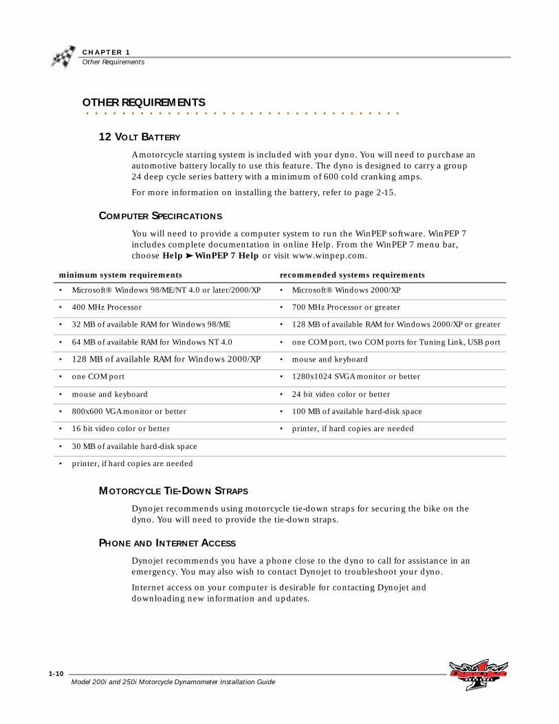
6 Remove the six 1/4-inch screws securing the top cover on the dyno and remove the cover.Note: Dynojet recommends using a hardened 5/32-inch hex driver (such as Snap-On FA5E) to remove the 1/4-inch screws. A standard allen key may round off in the shallow screw head.
7 Remove the tire stop, tire lock, and hardware from the middle of the dyno.
Figure 2-2: Remove the Top Cover
top cover
tire stop and tire lock in middle

Model 200i and 250i Motorcycle Dynamometer Installation Guide
C H A P T E R 2Unpacking and Inspecting the Dyno
2-4
8 Remove the eight screws securing the top drum cover to the dyno and set aside. Remove the drum cover and set aside.
9 Remove the two top screws securing each side drum cover to the dyno and set aside.
Figure 2-3: Remove the Top Drum Cover
top drum cover
side drum cover
side drum cover

I N S T A L L A T I O NUnpacking and Inspecting the Dyno
Version 2 Model 200i and 250i Motorcycle Dynamometer Installation Guide
2-5
10 Remove the remaining six side screws securing each side drum cover to the dyno and set aside. Remove the side drum covers and set aside.Note: For future reference, note the three access holes in the drum bulkhead. These access holes will be used to route cables when installing accessories once the top cover is back on.
Figure 2-4: Remove the Side Drum Covers
side drum cover
side drum cover
access holes in drum bulkhead (only two
visible from this view)

Model 200i and 250i Motorcycle Dynamometer Installation Guide
C H A P T E R 2Unpacking and Inspecting the Dyno
2-6
ROUTING THE COMPUTER, PENDANT, AND STARTER CABLES
1 With the top cover off, route the computer cable through the front access hole on the dyno.Note: You will need to remove the access panel in order to route the cables through it.
1a Remove the two screws securing the access panel to the dyno.1b If needed, cut a slit in the grommet in order to fit the grommet around the
cables.1c Replace the access panel using the screws removed earlier.
2 Route the pendant and starter button cables through one of the top access panels on the dyno.Note: You will need to pull the dyno electronics enclosure out in order to get the cables through the access panel on the left.
2a Remove the four screws securing the electronics enclosure.2b Slide the enclosure out of the dyno.2c Route the pendant and starter button cables through the access panel.2d Replace the electronics enclosure.
Figure 2-5: Route Computer, Pendant, and Starter Cables
route starter button cable through top
access panel
route computer cable through front access
panel
slide electronics enclosure out
route pendant cable through top access
panel

I N S T A L L A T I O NUnpacking and Inspecting the Dyno
Version 2 Model 200i and 250i Motorcycle Dynamometer Installation Guide
2-7
INSTALLING THE THETA CONTROLLER
With the top cover off, now is a good time to install the Theta Controller. You will only have a Theta Controller if you ordered an Eddy Current Brake. The Theta Controller is shipped in the eddy current brake crate. For more information on unpacking the eddy current brake, refer to page 4-19.
1 Secure the Theta Controller to the drum module bulkhead using four 8-32 x 3/8-inch screws.
2 Attach the input power cable to the Theta Controller (on top).3 Route the control cable from the Theta Controller to the Breakout Board through
the hole in the power distribution enclosure shown in Figure 2-6.
The control cable will be connected to the Breakout board on page 4-26.
4 Replace the top cover using the screws you removed earlier. Refer to Figure 2-2.
Figure 2-6: Install the Theta Controller
route control cable through opening in
electronics box
theta controller
attach input power cable on top

Model 200i and 250i Motorcycle Dynamometer Installation Guide
C H A P T E R 2Unpacking and Inspecting the Dyno
2-8
INSTALLING THE TIRE CARRIAGE
You will need to install the tire carriage on the dyno before removing the dyno from the crate (helps balance the dyno during lifting). Be sure the location you have chosen for your dyno has enough room in front of the dyno for the maximum extension of the carriage. Refer to “Dynamometer Specifications” on page 1-5 for more information.
The tire carriage is fastened to the bottom of the crate next to the dyno. Refer tostep 4 on page 2-2 for instructions on removing the tire carriage from the crate.
1 Install the three carriage clamps and shims using two 5/16-inch bolts and washers each.
2 Install the nut block and shim using two 5/16-inch bolts and washers.
Figure 2-7: Install the Carriage Clamps and Nut Block
carriage clampshim
nut block
shim

I N S T A L L A T I O NUnpacking and Inspecting the Dyno
Version 2 Model 200i and 250i Motorcycle Dynamometer Installation Guide
2-9
3 Using a 5/32-inch allen wrench, remove the two 1/4 x 1/2-inch button-head screws securing the screw support bracket. Remove the bracket and set the screws and bracket aside.
Figure 2-8: Remove the Screw Support Bracket
4 Slide the carriage under the carriage clamps and the nut block until the carriage screw is touching the nut block.
5 Slide the hand crank onto the end of the carriage screw.6 Secure the hand crank to the screw shaft by tightening the set screw using a
5/32-inch allen wrench.
Figure 2-9: Install the Tire Carriage and Secure the Hand Crank
carriage screw
screw support bracket
hand crank
carriage

Model 200i and 250i Motorcycle Dynamometer Installation Guide
C H A P T E R 2Unpacking and Inspecting the Dyno
2-10
7 Using the hand crank, screw the carriage through the nut block.8 Install the screw support bracket.
8a Place the belleville washers over the end of the carriage screw. It is important the belleville washers are installed in the configuration shown in Figure 2-10.
8b Place the screw support bracket in front of the carriage screw. The two threaded holes in the bracket should face the two matching holes in the carriage. Loosely install the two 1/4 x 1/2-inch button-head screws.
8c Before tightening the screws, apply some pressure to the bracket to compress the belleville washers. The handle should still turn freely, but the turning force should now be around five to six pounds.
To adjust the force needed to turn the crank handle, adjust the compression of the belleville washers.
8d Using a 5/32-inch allen wrench, tighten the two button-head screws.9 Tighten the clamp and nut block bolts with a 1/2-inch wrench.
Figure 2-10: Install the Screw Support Bracket
screws
support bracket
belleville washers
carriage screw

I N S T A L L A T I O NUnpacking and Inspecting the Dyno
Version 2 Model 200i and 250i Motorcycle Dynamometer Installation Guide
2-11
10 Secure the tire stop to the carriage with four 3/8 x 1/2-inch bolts.11 Secure the tire lock to the tire carriage using four 3/8 x 1/2-inch bolts.
Figure 2-11: Install the Tire Stop and Tire Lock
tire stop
tire lock

Model 200i and 250i Motorcycle Dynamometer Installation Guide
C H A P T E R 2Unpacking and Inspecting the Dyno
2-12
REMOVING THE DYNO FROM THE CRATE
You will need to provide equipment capable of lifting a minimum of 1600 lb. (725 kg.) to lift the dyno off the crate and into position in your dyno room. You will also need a pair of straps capable of supporting 1600 lb. (725 kg.) to attach to the dyno. Dynojet recommends using single loop style straps.
1 Remove the four lag bolts and washers securing the dyno to the crate base using a 9/16-inch socket, open or box end wrench.
2 The pickup card may be taped to the lifting eye. Remove the pickup card and set it aside.
3 Wrap the single loop straps through the lifting eyes in front of the drum.4 Lift the dyno off the crate and move into position in your dyno room.
Figure 2-12: Remove the Dyno from the Crate Base
bolt and washer not visible from this view
lifting eye
bolt and washer
bolt and washer
lifting eye
bolt and washer

I N S T A L L A T I O NUnpacking and Inspecting the Dyno
Version 2 Model 200i and 250i Motorcycle Dynamometer Installation Guide
2-13
5 Secure the dyno to the floor in your dyno room. Skip this step if you will be installing the eddy current brake.Note: Dynojet recommends you secure your dyno to the floor in your dyno room using concrete anchors. You will want to mark and drill the holes in your concrete before adding any accessories or replacing the covers on your dyno.
5a Mark and drill holes.5b Refer to Appendix A for Red Head Anchor installation instructions.
Figure 2-13: Anchor Hole Placement
mark and drill holes
hole not visible from this view
mark and drill hole

Model 200i and 250i Motorcycle Dynamometer Installation Guide
C H A P T E R 2Pickup Card
2-14
. . . . . . . . . . . . . . . . . . . . . . . . . . . . . . . . . . .PICKUP CARD
The pickup card is an electronic circuit board that accurately senses each drum revolution.
1 Locate the pickup card bracket on the right side of the dyno just ahead of the drum.
2 Install the pickup card to the bracket using two No. 8 screws. Do not tighten, the card must be aligned first.Note: If your dyno is equipped with an air brake, you will need to attach compressed air and power to your dyno before you can turn the drum. Refer to the page 4-4 for more information on attaching compressed air to your dyno.
3 Align the optical pickup card with the tab on the dyno drum axle. Be sure the tab passes freely through the optical pickup. You may need to loosen the bracket to help with alignment.
4 Once aligned, tighten the screws to secure the pickup card in place.
The optical pickup is very delicate. Be careful not to damage the optical pickup during alignment.
Figure 2-14: Install the Pickup Card
pickup card bracket
pickup card
tab on dyno
top view of pickup card, optical pickup, and tab on dyno
tab on dyno
optical pickup
pickup card

I N S T A L L A T I O NBattery
Version 2 Model 200i and 250i Motorcycle Dynamometer Installation Guide
2-15
. . . . . . . . . . . . . . . . . . . . . . . . . . . . . . . . . . .BATTERY
A bike starting system is included with your Dynojet dyno. You will need to provide an automotive battery to use this system. The dyno is designed to carry a group 24 series battery with a minimum of 600 cold cranking amps.
1 Locate the red battery cable on the inside of the dyno. 2 Place the battery in the battery carrier on the inside of the dyno so the red cable
can reach the positive (+) post on the battery and the black battery cable can reach the negative (-) post.
3 Secure the red battery cable to the positive (+) battery post.4 Secure the black battery cable to the negative (-) battery post.5 Secure the battery to the tray with the battery hold-down.
Figure 2-15: Install the Battery
battery

Model 200i and 250i Motorcycle Dynamometer Installation Guide
C H A P T E R 2Replace the Drum Side and Top Covers
2-16
. . . . . . . . . . . . . . . . . . . . . . . . . . . . . . . . . . .REPLACE THE DRUM SIDE AND TOP COVERS
Before replacing the covers, be sure to install the battery, pickup card, eddy current brake, and any accessories you may have purchased with your dyno. Refer to chapter four for accessory installation instructions.
1 Secure each side drum cover to the dyno using the six screws you removed earler.
Figure 2-16: Replace the Side Drum Covers
side drum cover
side drum cover

I N S T A L L A T I O NReplace the Drum Side and Top Covers
Version 2 Model 200i and 250i Motorcycle Dynamometer Installation Guide
2-17
2 Secure the top of the side drum covers with the screws you removed earlier.3 Secure the top drum cover to the dyno using the eight screws removed earlier.
Note: Drum guards must be adjusted to less than 5 mm from the surface of the drum.
Figure 2-17: Replace the Top Drum Cover
top drum cover

Model 200i and 250i Motorcycle Dynamometer Installation Guide
C H A P T E R 2Ramp Bracket
2-18
. . . . . . . . . . . . . . . . . . . . . . . . . . . . . . . . . . .RAMP BRACKET
The ramp bracket allows you to attach your own ramp to the dyno. You will need to modify your ramp to secure it to the ramp bracket.
1 With the ramp upside down, center the ramp bracket under the lip at the top of the ramp.
2 Using the larger holes on the bracket, mark and drill two 3/8-inch holes in the ramp.
Figure 2-18: Ramp Assembly
ramp lip
ramp bracket
24 inches

I N S T A L L A T I O NRamp Bracket
Version 2 Model 200i and 250i Motorcycle Dynamometer Installation Guide
2-19
3 Insert the 3/8-inch bolts from the top of the ramp and secure using 3/8-inch washers and nuts.
Figure 2-19: Secure Bolts to Ramp
4 Remove the four 1/4-inch bolts from the rear of the drum cover.5 Secure the ramp bracket to the rear drum cover using the bolts you just removed.
Figure 2-20: Secure Bracket to Drum Cover

Model 200i and 250i Motorcycle Dynamometer Installation Guide
C H A P T E R 2Ramp Bracket
2-20
6 Place the ramp on the ramp bracket slipping the bolts on the ramp through the large holes on the ramp bracket.
Figure 2-21: Place Ramp on Dyno

I N S T A L L A T I O NGround Hooks
Version 2 Model 200i and 250i Motorcycle Dynamometer Installation Guide
2-21
. . . . . . . . . . . . . . . . . . . . . . . . . . . . . . . . . . .GROUND HOOKS
You may wish to install additional ground hooks (included with your dyno) for securing the motorcycle. Use the following instructions as a guide in placing your ground hooks.
1 Locate each ground hook approximately 96.5 cm (38 inches) from the front of the dyno and approximately 20 cm (8 inches) from the side of the dyno (approximately 147 cm, 58 inches, apart).
2 Using the ground hooks as a pattern, install the Red Head Anchors using the hardware included with the ground hook kit. Refer to Appendix A for Red Head Anchor installation instructions.
Figure 2-22: Ground Hooks
approx. 147 cm (58 in.)
approx. 20 cm (8 in.)
approx. 96.5 cm
(38 in.)


Model 200i and 250i Motorcycle Dynamometer Installation Guide3-1
C H A P T E R
3DYNO ELECTRONICS
This chapter provides instructions for installing the dyno electronics. To ensure safety and accuracy in the procedures, perform the procedures as they are described.
This chapter is divided into the following categories:
• Dyno Electronics, page 3-2
• Atmospheric Sensing Module, page 3-2
• RPM Module, page 3-3
• Dynamometer Input/Output Module, page 3-4
• CPU Module, page 3-5
• Accessing the Dyno Electronics, page 3-6

Model 200i and 250i Motorcycle Dynamometer Installation Guide
C H A P T E R 3Dyno Electronics
3-2
. . . . . . . . . . . . . . . . . . . . . . . . . . . . . . . . . . .DYNO ELECTRONICS
The standard DynoWare EX+ dynamometer electronics package is comprised of four interconnected modules: Atmospheric Sensing Module, RPM Module, Dynamometer Input/Output Module, and the CPU Module.
Figure 3-1: Dyno Electronics
ATMOSPHERIC SENSING MODULE
The atmospheric sensing module measures absolute pressure, air temperature, and relative humidity. These measurements are used by WinPEP to correct power and torque measurements to standard atmospheric conditions according to a DIN, SAE, or other formula.
LED indicator descriptionThe green LED glows when the atmospheric sensing module is receiving power.
The flashing amber LED indicates the module processor is operating properly.
system expansion connector
atmospheric sensing module
RPM module
dynamometer input/output module
CPU module
inductive pickup socket
25-pin socket
9-pin, RS-232 socket
9-pin, hand held pendant
3-pin power plug

D Y N O E L E C T R O N I C SDyno Electronics
Version 2 Model 200i and 250i Motorcycle Dynamometer Installation Guide
3-3
RPM MODULE
The RPM module receives and processes signals from up to two inductive pickups for measurement of engine RPM. Each input has an automatic gain circuit to compensate for a wide variance of ignition systems.
Figure 3-2: RPM Module
LED indicator descriptionThe green LED glows when the RPM module is receiving power.
The amber LED flashes when an RPM signal is detected. A steady flash rate, proportional to engine RPM, indicates a good RPM signal.
These connectors are the inputs for both primary and secondary inductive pickup clips. Either input may be used with a primary inductive pickup or a secondary inductive pickup on a single ended coil. Both inputs can be used for a wasted spark ignition.

Model 200i and 250i Motorcycle Dynamometer Installation Guide
C H A P T E R 3Dyno Electronics
3-4
DYNAMOMETER INPUT/OUTPUT MODULE
The dynamometer input/output module sends and receives data from the dynamometer and the hand-held pendant. The module also contains a buzzer and light which are activated when either the vehicle or the dynamometer speed limit is approached.
Figure 3-3: Dynamometer Input/Output Module
LED indicator descriptionThe green LED glows when the dynamometer input/output module is receiving power.
The amber LED flashes proportionally to dynamometer drum RPM.
This 25-pin connector attaches to the shielded cable from the dynamometer.
This 9-pin connector attaches to the hand held pendant which houses the button used to start/stop acquiring data. The pendant may also contain a brake switch.

D Y N O E L E C T R O N I C SDyno Electronics
Version 2 Model 200i and 250i Motorcycle Dynamometer Installation Guide
3-5
CPU MODULE
The CPU module contains a 32-bit processor which acquires data from the expansion modules and communicates to the main computer running the WinPEP software. The processor queries the expansion modules to determine their identity and capabilities.
Figure 3-4: CPU Module
LED indicator descriptionThe green LED glows when the CPU module is receiving power.
The blue LED is lighted when data from the modules is being acquired and saved.
One of these connectors is used to communicate to the main computer. The 9-pin connector (left) attaches to the PC’s RS-232 serial communications port.
This connector provides a synchronization signal to a third party data acquisition system.
This connector provides 12 volt DC power to a third party data acquisition system.
This connector accepts 12 volt DC power from a power supply or battery. The adjacent LED glows bright green when power is properly connected.
When this switch is on, power is supplied to all connected modules.

Model 200i and 250i Motorcycle Dynamometer Installation Guide
C H A P T E R 3Accessing the Dyno Electronics
3-6
. . . . . . . . . . . . . . . . . . . . . . . . . . . . . . . . . . .ACCESSING THE DYNO ELECTRONICS
You may need to access your dyno electronics in order to add modules or perform any troubleshooting. Use the following steps to access the dyno electronics.
To prevent possible injury, place the breaker inside the power distribution enclosure to the off position and unplug the dyno. Refer to Figure 1-4 for breaker location.
1 Remove the four screws securing the dyno electronics enclosure and set aside.2 Slide the enclosure toward you and out of the dyno. Be sure not to pinch or pull
any cables.
Figure 3-5: Remove the Dyno Electronics Enclosure

D Y N O E L E C T R O N I C SAccessing the Dyno Electronics
Version 2 Model 200i and 250i Motorcycle Dynamometer Installation Guide
3-7
3 Remove the 12 screws securing the cover and lift the cover off.
Figure 3-6: Remove Electronics Enclosure Cover
Figure 3-7: Inside the Electronics Enclosure
dyno electronics
power supply
power switch
RPM connectors


Model 200i and 250i Motorcycle Dynamometer Installation Guide4-1
C H A P T E R
4ACCESSORIES
This chapter discusses the various optional accessories that are available for the Dynojet Motorcycle Dynamometer (dyno) to meet your individual needs. All of these options can be added at the factory at the time of original dyno purchase, or purchased separately and added at any time thereafter. For more information about these accessories, please contact Dynojet’s Product Specialist’s at 1-800-992-3525 for pricing and availability.
Installation instructions for some of these options can be found in this chapter. Complete installation instruction manuals may also be found by browsing the Manuals folder on your WinPEP installation CD
This chapter is divided into the following categories:
• Removing and Replacing Drum Covers, page 4-2
• Air Brake, page 4-4
• Air Pump and Filter Assembly, page 4-11
• Eddy Current Brake, page 4-18
• Extended Carriage, page 4-30
• High Pressure Blower, page 4-38
• Monitor Tray, page 4-42
• Power Carriage, page 4-44
• Safety Switch, page 4-48

Model 200i and 250i Motorcycle Dynamometer Installation Guide
C H A P T E R 4Removing and Replacing the Top and Side Drum Covers
4-2
. . . . . . . . . . . . . . . . . . . . . . . . . . . . . . . . . . .REMOVING AND REPLACING THE TOP AND SIDE DRUM COVERS
You will need to remove and replace the drum top and side covers to access many of the accessory areas. Refer to the following instructions.
1 Remove the eight screws securing the top drum cover to the dyno and set aside. Remove the drum cover.
2 Remove the two screws securing the top of each side drum cover to the dyno and set aside.
Figure 4-1: Remove the Top Drum Cover
side drum cover
top drum cover
side drum cover

A C C E S S O R I E SRemoving and Replacing the Top and Side Drum Covers
Version 2 Model 200i and 250i Motorcycle Dynamometer Installation Guide
4-3
3 Remove the remaining six screws securing each side drum cover to the dyno and set aside. Remove the side drum covers.
Figure 4-2: Remove the Side Drum Covers
side drum cover
side drum cover
Model 200i and 250i Motorcycle Dynamometer Installation Guide
C H A P T E R 4Air Brake
4-4
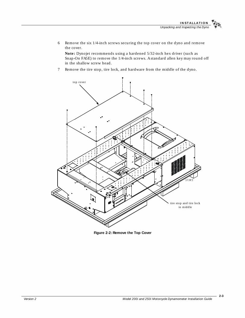
. . . . . . . . . . . . . . . . . . . . . . . . . . . . . . . . . . .AIR BRAKE
The air brake comes installed and ready to use. You will need to provide an air hose nipple (1/4-inch NPT) to connect your clean, dry shop air supply (60 psi, 415 kilopascal, max constant line pressure) to the dynamometer. Once air pressure is connected, the air brake is ready to use.
Figure 4-3: Connect Your Shop Air Supply
PARTS LIST
The following table lists all of the parts included in the Air Brake (P/N 63920005) Installation kit. Check your kit against the parts listed to make sure you have received all of the parts. If any part is missing, contact Dynojet Technical Support.
part number description quantity21222201 Brake Caliper Stop 121222601 Brake Adjusting Shim 121622201 Brake Bracket 132904080 Hairpin Cotter, 7/16-3/4” shaft size 332920128 Clevis Pin, 5/8 x 4” 236488100 Nut, 3/8-16, Nylock 136581270 Bolt, 3/8-16 x 3/4”, with Taper lock 236585670 Bolt, 3/8-16 x 3-1/2”, Hex 136820840 Bolt, 5/8-11 x 1, Hex 236952100 Washer, 5/8”, splitlock, stl 237620844 Woodruff Key, 1/2 x 2-3/4”, #1622-1 163920004 Air Brake Assembly 163990002 Rotor/Taper Lock Assembly with Hub and Key 1BR102-055 Purple Brake Spring 1DM150-002-007 Washer, 5/16”, Flat 3
connect shop air supply

A C C E S S O R I E SAir Brake
Version 2 Model 200i and 250i Motorcycle Dynamometer Installation Guide
4-5
FINAL ADJUSTMENTS AND TESTS
1 Verify the dyno is set up properly, the dyno electronics is powered up and operational, and the air supply is connected properly.
2 Use the red brake button on the pendant to activate and deactivate the brake. Listen for air leaks and double check all connections.
3 Verify the brake pads release far enough so they do not touch the rotor. There should be equal pad clearance on both sides of the rotor. If the pads touch the rotor during a run, the information provided by the dyno will be inaccurate.
Refer to page 4-10 for instructions on adjusting the brake pad clearance.
CHANGING THE BRAKE PADS
To prevent possible injury, place the breaker inside the power distribution enclosure to the off position and unplug the dyno. Refer to Figure 1-4 for breaker location.
1 Remove the top and right side covers from the dyno. Refer to page 4-2.2 For safety, apply the brake and disconnect the air supply at the front of the dyno.
Refer to Figure 4-3 on page 4-4.3 Remove the hairpin cotter and loosen the castle nut until the pads clear the rotor.
Figure 4-4: Loosen the Castle Nut
remove hairpin cotteradjust castle nut
outboard brake pad

Model 200i and 250i Motorcycle Dynamometer Installation Guide
C H A P T E R 4Air Brake
4-6
4 Using a 9/16-inch ratchet and wrench, remove the bolt, washer, and nut securing the spring to the brake assembly. The spring is located on the drum side of the brake assembly.Note: For clarity, the drum is not shown.
Figure 4-5: Remove the Purple Spring
bolt
boltnut, washer, and spring
nut, washer, and spring

A C C E S S O R I E SAir Brake
Version 2 Model 200i and 250i Motorcycle Dynamometer Installation Guide
4-7
5 Remove the two bolts and two washers securing the brake caliper stop to the brake bracket and remove the brake caliper stop.Note: For clarity, the drum and parts of the dyno frame are not shown.
Figure 4-6: Remove the Brake Caliper Stop
6 Remove the hairpin cotter from the bottom clevis pin located on the front of the air brake assembly.
Figure 4-7: Remove Bottom Hairpin Cotter
brake caliper stop brake bracket
bottom clevis pinhairpin cotter

Model 200i and 250i Motorcycle Dynamometer Installation Guide
C H A P T E R 4Air Brake
4-8
7 Push the bottom clevis pin towards the back of the assembly (drum side). You do not need to remove the pin completely.
8 Remove the hairpin cotter from the top clevis pin located on the drum side of the air brake assembly.
Figure 4-8: Remove Bottom Pin and Top Hairpin Cotter
9 Remove the top clevis pin.
Figure 4-9: Remove the Top Clevis Pin
bottom clevis pin
top hairpin cottertop clevis pin
top clevis pin

A C C E S S O R I E SAir Brake
Version 2 Model 200i and 250i Motorcycle Dynamometer Installation Guide
4-9
10 Lift the air brake assembly up and away from the dyno.
Figure 4-10: Remove the Brake Assembly
11 Remove the brake pad retaining springs and slide the pads out.Note: You will need to use pliers to remove the spring securing the outside pad (closest to the castle nut).
12 Install the new brake pads and secure the pads with new springs.13 Place the air brake assembly back on the brake bracket. Refer to Figure 4-10.14 Replace the top and bottom clevis pins and secure with the hairpin cotters
removed earlier. Refer to Figure 4-7, Figure 4-8, and Figure 4-9.15 Using two bolts and two washers, secure the brake caliper stop to the brake
bracket. Refer to Figure 4-6.16 Secure the spring using the bolt, washer, and nut you removed earlier. Refer to
Figure 4-5.17 Tighten the castle nut and replace the hair pin cotter. Refer to Figure 4-4.18 Adjust the brake pad clearance. Refer to page 4-10 for complete instructions.19 Replace the top and right side covers. Refer to page 4-2.20 Connect your shop air.

Model 200i and 250i Motorcycle Dynamometer Installation Guide
C H A P T E R 4Air Brake
4-10
ADJUSTING THE BRAKE PAD CLEARANCE
There should be equal pad clearance on both sides of the rotor. If the pads touch the rotor during a run, the information provided by the dyno will be inaccurate. Use the following steps to adjust the clearance.
1 Loosen the brake caliper stop bolts.2 Insert the brake adjusting shim between the inboard brake pad and the brake
rotor. Refer to Figure 4-11.3 Remove the hairpin cotter and hand tighten the castle nut on the caliper assembly
to clamp the brake pads against the rotor and shim. Refer to Figure 4-4 for hairpin and castle nut location.
4 Tighten the brake caliper stop bolts.5 Loosen the castle nut and remove the shim.6 Adjust the clearance between the outboard brake pad and rotor. Loosen the castle
nut to increase the clearance.
There should be equal space on both sides of the rotor.
7 Replace the hair pin cotter in the castle nut.Note: Cycle the brake to verify the brake pads release far enough so they do not touch the rotor. If the pads touch the rotor during a run, the information provided by the dyno will be inaccurate.
Figure 4-11: Adjust Brake Pad Clearance
brake adjusting shim
inboard brake pad
rotor
brake caliper stop bolts

A C C E S S O R I E SAir Pump and Filter Assembly
Version 2 Model 200i and 250i Motorcycle Dynamometer Installation Guide
4-11
. . . . . . . . . . . . . . . . . . . . . . . . . . . . . . . . . . .AIR PUMP AND FILTER ASSEMBLY
This section describes how to install the on dyno air pump and filter assembly.
• Dynojet recommends running the pump between dyno runs to help reduce the chance of moisture contamination on the sensor.
• Remember to empty the exhaust collection bottles regularly.
• Leaks in the system will result in erroneous readings. Verify there are no cracks or holes in the hoses and filter bowl. Verify the sensor is seated properly in the sensor block.
• Do not allow the filter bowl to fill with water during operation. Refer to the Air Fuel Ratio Module User Guide for filter bowl information.
• Before turning the pump on, verify there is no water in the filter bowl. Always empty the bowl before turning the pump on.
• Always allow the air pump to run after the dyno runs are complete to clear all water from the filter bowl and allow the air pump to cool.
Refer to the Air Fuel Ratio Module Installation and User Guide for proper operating and maintenance procedures. Failure to follow proper procedures may result in inaccurate data or damage to the equipment. This manual can be found on your WinPEP CD or at www.dynojet.com/manuals.shtml.
Note: The Air Pump Assembly has a twelve month warranty.
Leaded racing fuels and two-stroke applications will contaminate the sensor and dramatically shorten its service life.
The sensor is not covered by a warranty. Be sure to read and understand the Air Fuel Ratio Module manuals.
Running the pump with the filter clogged, hose kinked, or filter removed will damage the pump and void the warranty.

Model 200i and 250i Motorcycle Dynamometer Installation Guide
C H A P T E R 4Air Pump and Filter Assembly
4-12
PARTS LIST
The following table lists all of the parts included in the Air Pump and Filter Assembly (P/N 64193009 Domestic or P/N 64193010 European) Installation kit. Check your kit against the parts listed to make sure you have received all of the parts. If any part is missing, contact Dynojet Technical Support.
INSTALLING THE FILTER AND PUMP ASSEMBLIES
1 Remove the side drum cover from the right side of the dyno. Refer to “Removing and Replacing the Top and Side Drum Covers” on page 4-2.
2 Remove the four 1/4-inch screws securing the AFR blanking plate to the dyno and remove the plate. Set the screws aside, they will be used later.
3 Remove the lower two 3/8-inch bolts, washers, and nuts from the lower right corner of the rear of the dyno and set aside to be used later.
Figure 4-12: Remove the Blanking Plate
part number description quantity21125500 Filter and Sensor Housing 121626204 Pump Bracket 121696204 Pump Bottle Bracket 131991331 1/2” Diameter Rubber Hose 234420001 Filter Assembly 134491000 Filter Kit Replacement 539460210 Drip Bottle, Clear, Plastic 243310600 Grommet, 7/16” ID x 3/4” OD 246115050or46115051
Pump, Thomas 2107, 120VorPump, Thomas 2107, 240V
1
lower bolts, washers, and nuts
blanking plate

A C C E S S O R I E SAir Pump and Filter Assembly
Version 2 Model 200i and 250i Motorcycle Dynamometer Installation Guide
4-13
4 Install the filter assembly with the four 1/4-inch screws removed in step two.
Figure 4-13: Install the Filter Assembly
5 Install the pump assembly and exhaust bottle bracket using the two 3/8-inch bolts removed in step 3.
Figure 4-14: Install the Pump Assembly
filter assembly
pump assembly
exhaust bottle bracket

Model 200i and 250i Motorcycle Dynamometer Installation Guide
C H A P T E R 4Air Pump and Filter Assembly
4-14
6 Connect the 1/4-inch inlet hose and the 1/8 inlet hose.
Figure 4-15: Connect the Inlet Hoses
7 Install two grommets and the outlet hoses as shown in Figure 4-16.8 Install the exhaust bottles and insert the outlet hoses into the bottles.
Figure 4-16: Install the Exhaust Bottles, Hoses, and Grommets
1/4-inch inlet hose
1/8-inch inlet hose
grommets
outlet hoses
exhaust bottles

A C C E S S O R I E SAir Pump and Filter Assembly
Version 2 Model 200i and 250i Motorcycle Dynamometer Installation Guide
4-15
9 Attach the sensor to the sensor block.10 Attach the sensor cable to the corresponding cable from the inside back panel of
the dyno.
Figure 4-17: Install the Sensor
11 Locate the wiring harness coming from the switch at the bottom of the filter assembly. This wiring harness has two connectors. One connector attaches to the pump while the other attaches to the dyno. 11a Attach the female three-pin connector to the pump cable.11b Attach the male three-prong connector to the black power cord from the
dyno. This power cord is located on the inside back panel of the dyno.12 Replace the right side drum cover. Refer to “Removing and Replacing the Top and
Side Drum Covers” on page 4-2.
CLEANING THE FILTER ASSEMBLY
Refer to the Air Fuel Ratio Module Installation and User Guide for detailed filter assembly cleaning procedures. Failure to follow proper procedures may result in inaccurate data or damage to the equipment. This manual can be found on your WinPEP CD or at www.dynojet.com/manuals.shtml.
If cleaning the filter does not result in free air flow, replace the filter. Be sure to check for other restrictions in the system.
Note: A clogged filter may cause erroneous readings or slow response. Clean the filter daily or more often depending on usage.
sensor
back view of filter assembly
sensor cable

Model 200i and 250i Motorcycle Dynamometer Installation Guide
C H A P T E R 4Air Pump and Filter Assembly
4-16
PUMP HEAD MAINTENANCE
Depending on usage, the pump will need periodic maintenance. Use the following instructions to remove the pump from the dyno. Once removed, refer to the Air Fuel Ratio Module Installation and User Guide for detailed pump head maintenance procedures.
To prevent possible injury, place the breaker inside the power distribution enclosure to the off position and unplug the dyno. Refer to Figure 1-4 for breaker location.
1 Remove the exhaust collection bottles from the bracket.2 Disconnect the outlet hoses from the pump.
Figure 4-18: Remove the Exhaust Bottles, Hoses, and Grommets
3 Disconnect the 1/4-inch inlet hose and the 1/8 inlet hose.
Figure 4-19: Disconnect the Inlet Hoses
outlet hoses
exhaust collection bottles
1/4-inch inlet hose
1/8-inch inlet hose

A C C E S S O R I E SAir Pump and Filter Assembly
Version 2 Model 200i and 250i Motorcycle Dynamometer Installation Guide
4-17
4 Remove the two 3/8-inch bolts securing the bracket to the pump assembly and set the bolts and bracket aside.
5 Remove the pump assesmbly.
Figure 4-20: Remove the Pump Assembly
6 Remove the four screws securing the pump to the bracket and set aside.7 Remove the pump from the bracket.
Figure 4-21: Remove the Pump from Bracket
8 Refer to the Air Fuel Ratio Module Installation and User Guide for detailed pump head maintenance procedures. Failure to follow proper procedures may result in inaccurate data or damage to the equipment. This manual can be found on your WinPEP CD or at www.dynojet.com/manuals.shtml.
pump assembly
bottle bracket
pumpbracket

Model 200i and 250i Motorcycle Dynamometer Installation Guide
C H A P T E R 4Eddy Current Brake
4-18
. . . . . . . . . . . . . . . . . . . . . . . . . . . . . . . . . . .EDDY CURRENT BRAKE
This section will walk you through removing the eddy current brake from the crate, attaching the brake to your dyno, routing and wiring the temperature sensor cable to the Breakout board, and wiring the Theta Controller to the Breakout Board.
You will need to provide equipment capable of lifting the eddy current brake off the crate and into position in your dyno room. You will also need a pair of straps. Dynojet recommends using continuous nylon loop style straps.
To prevent possible injury, place the breaker inside the power distribution enclosure to the off position and unplug the dyno. Refer to Figure 1-4 for breaker location.
PARTS LIST
The following table lists all of the parts included in the Eddy Current Brake (P/N 63223700) Installation kit. Check your kit against the parts listed to make sure you have received all of the parts. If any part is missing, contact Dynojet Technical Support.
part number description quantity21227107 Retarder Connector Plate (already installed) 221629403 Bar, Load Cell 136582034 Screw, 3/8”-16 x 1 1/4”, BH-FLNG 837620622 Woodruff Key, 3/8” x 1 3/8” 149950030 Temperature Sensor 161228400 Hood, Top, Retarder Module 163223700 Retarder Module 166411003 Theta-2 Controller 240V 1

A C C E S S O R I E SEddy Current Brake
Version 2 Model 200i and 250i Motorcycle Dynamometer Installation Guide
4-19
UNPACKING THE EDDY CURRENT BRAKE
1 Remove the top and sides of the crate.2 Remove the four screws securing the top cover and set aside. Remove the cover
and set aside.3 Remove the hardware box and Theta Controller from the crate and verify the
hardware box contents using the parts list.
For more information on installing the Theta Controller refer to page 2-7.
Figure 4-22: Remove the Covers
top cover

Model 200i and 250i Motorcycle Dynamometer Installation Guide
C H A P T E R 4Eddy Current Brake
4-20
4 Remove the four bolts securing the brake to the crate.5 Determine if the brake is to be mounted on the left or right side of your dyno.
Make the following adjustments to the eddy current brake only if you want to mount the brake on the opposite side of the dyno that it is currently set up for.
5a Move the coupler and key to the other side of the brake.• To remove the key, use a punch and a hammer to apply pressure in the
direction of the arrows shown in Figure 4-24.5b Move the retarder connector plates to the other side of the brake.5c Move the temperature sensor to the other side of the brake.
Figure 4-23: Identifying Left or Right Side Brake Set Up
Figure 4-24: Removing the Key
retarder connector plates
eddy current brake set up for left side installation eddy current brake set up for right side installation
coupler
temperature sensor
front of dyno
retarder connector plates
apply force using hammer and punch
apply force using hammer and punch
shaft
key

A C C E S S O R I E SEddy Current Brake
Version 2 Model 200i and 250i Motorcycle Dynamometer Installation Guide
4-21
6 Remove the side drum cover, if not already removed, from the dyno. Refer to page 4-2.
7 Place the nylon loop strap through the lifting eyes on either side of the brake.8 Using a forklift, lift the eddy current brake from the crate and place the brake near
the dyno making sure the panels on the brake and dyno are parallel.9 Remove the eight bolts, washers, and nuts from the dyno frame where the
connector plates will attach.
Figure 4-25: Move the Brake Next to the Dyno
lifting eye
lifting eye
line up panels
remove bolts, washers, and nuts from dyno frame

Model 200i and 250i Motorcycle Dynamometer Installation Guide
C H A P T E R 4Eddy Current Brake
4-22
INSTALLING THE EDDY CURRENT BRAKE
The eddy current brake comes with the coupler already installed on the brake shaft.
The eddy current brake can be installed on either side of your dyno. It is not necessary to remove the air brake if you are installing the eddy current brake on the right side.
Note: Safety requirements of your local country may require that both brakes are installed. Be sure to follow the safety requirements specific to your country.
1 Insert the key into the keyway.2 Use a c-clamp to press the key in.
Figure 4-26: Install the Key
key way on dyno shaft
key
retarder connector plate

A C C E S S O R I E SEddy Current Brake
Version 2 Model 200i and 250i Motorcycle Dynamometer Installation Guide
4-23
3 Keeping the panels parallel, slide the eddy current brake towards the dyno. Slide the coupler over the key on the dyno shaft. You will need to support the coupler as you slide it onto the dyno shaft.
4 Continue sliding the eddy current brake towards the dyno until the covers on the brake and dyno are flush.
5 Secure the retarder connector plate to the dyno frame using the four bolts, washers, and nuts removed earlier. There is a retarder connector plate on either side of the brake. Refer to Figure 4-26.Note: Do not tighten the bolts.
6 Verify the covers on the brake and the dyno line up. These covers must be flush and parallel. If these covers are not flush, place shims between the floor and the eddy current brake or the dyno until they are flush.
7 Once aligned, tighten all retarder connector plate bolts and nuts.
Figure 4-27: Secure the Retarder Connector Plate
three bolts not visible from this view
retarder connector plate

Model 200i and 250i Motorcycle Dynamometer Installation Guide
C H A P T E R 4Eddy Current Brake
4-24
8 Secure the side panels on the eddy current brake to the panels on the dyno using a 1/4-20 bolt, washer, and nut. Do this on each side.
Figure 4-28: Secure the Side Panels to the Dyno
9 Replace the existing set screws on the coupler with the thread-lock set screws provided.
10 Tighten the coupler set screws.
Figure 4-29: Tighten the Set Screws
not visible from this view
brake shaft dyno shaft
set screw

A C C E S S O R I E SEddy Current Brake
Version 2 Model 200i and 250i Motorcycle Dynamometer Installation Guide
4-25
ROUTING CABLES
1 Route the temperature sensor cable from the eddy current brake through the air hole in the drum bulkhead, through the opening on the side of the power distribution enclosure, and over to the Breakout board.
For more information on wiring the Breakout board refer to page 4-26.
2 Attach the brake power cable from the eddy current brake through the air hole in the drum bulkhead to the Theta Controller (underneath).Note: The control cable was routed from the Theta Controller on page 2-7.
Figure 4-30: Route Cables
breakout board brake power cable
temperature sensor cable
theta controllerair hole in drum
bulkhead
control cable

Model 200i and 250i Motorcycle Dynamometer Installation Guide
C H A P T E R 4Eddy Current Brake
4-26
WIRING THE BREAKOUT BOARD
1 Attach the temperature sensor cable to the Breakout board. The temperature sensor cable has five wires which connect to the wiring block labeled TEMP. This cable was routed to the Breakout board on page 4-25.
2 Attach the control cable to the Breakout board. The control cable has five wires which connect to the wiring block labeled LOAD CONTROL. This cable was routed to the Breakout board on page 2-7.
3 Verify jumpers J1 and J2 are set either for the eddy current brake and air brake or for the air brake only as shown in Figure 4-31.
If you have an eddy current brake and air brake, the air brake will only be activated when the dyno electronics power is turned off or the optional door interlock is installed and activated.
4 Close the power distribution enclosure door.
Figure 4-31: Wire the Breakout Board
• Green wire connects to G1 • White wire connects to W1
• Black wire connects to B1 • Red wire connects to R1
• Ground (shield) wire connects to S1
• Black wire connects to V- • Red wire connects to V+
• White wire connects to O+ • Green wire connects to O-
• Ground (shield) wire connects to SH
jumpers J1 and J2
load control
eddy current brake and air brake jumper settings
air brake only jumper settings
temp

A C C E S S O R I E SEddy Current Brake
Version 2 Model 200i and 250i Motorcycle Dynamometer Installation Guide
4-27
REPLACING THE COVERS
Note: Dynojet recommends you anchor the eddy current brake, along with the dyno, to the floor in your dyno room.
1 Before you replace the covers, secure the eddy current brake and the dyno to the ground using Red Head Anchors. Refer to Appendix A for Red Head Anchor installation instructions.
Secure the eddy current brake to the ground using the same holes used to secure the brake to the crate.
2 Using the six of the eight screws removed earlier, secure the side cover to the brake.
Figure 4-32: Install the Side Cover
side cover

Model 200i and 250i Motorcycle Dynamometer Installation Guide
C H A P T E R 4Eddy Current Brake
4-28
3 Using two of the eight screws removed earlier, secure the top part of the side cover to the brake.
4 Using the four screws removed earlier and two 1/4 x 1/2-inch screws, secure the top cover to the brake and dyno.Note: If you are unable to secure the covers, then the brake may not be properly aligned with the dyno. You should not need to force the covers on.
Figure 4-33: Install the Top Cover
top cover
top of side cover
side cover screws

A C C E S S O R I E SEddy Current Brake
Version 2 Model 200i and 250i Motorcycle Dynamometer Installation Guide
4-29
REPLACING THE THETA CONTROLLER FUSES
The Theta controller has two fuses. For more information on installing the Theta Controller refer to page 2-7.
Hazardous voltage. To avoid risk of electrical shock, place the breaker inside the power distribution enclosure to the off position and unplug the dyno. Refer to Figure 1-4 for breaker location.1 Open the power distribution enclosure cover.2 Remove the four screws securing the blanking plate and remove the plate.3 Reach through this opening to access the fuses on the Theta Controller.4 Gently push the fuse holder slightly inward and rotate counterclockwise. Remove
the fuse holder.5 Replace the fuse with a fuse type listed below.
For continued protection against risk of fire, replace only with a fuse of the same type and having the same electrical rating.
• Buss P/N BAF-15, 15A Fuse• Little Fuse, KLK 15• Fast Blow, Dynojet P/N 54211201
Figure 4-34: Replace Theta Controller Fuses
reach through opening to theta controller fuses
remove blanking plate

Model 200i and 250i Motorcycle Dynamometer Installation Guide
C H A P T E R 4Extended Carriage
4-30
. . . . . . . . . . . . . . . . . . . . . . . . . . . . . . . . . . .EXTENDED CARRIAGE
The extended carriage option increases the maximum wheel base (measured from the front of the front wheel to the center of the rear wheel) from 84 inches to 102 inches for testing raked cruisers and drag bikes.
To prevent possible injury, place the breaker inside the power distribution enclosure to the off position and unplug the dyno. Refer to Figure 1-4 for breaker location.
PARTS LIST
The following table lists all of the parts included in the Extended Carriage Installation kit. Check your kit against the parts listed to make sure you have received all of the parts. If any part is missing, contact Dynojet Technical Support.
part number description quantity36488100 Nut, 3/8"-16, Nylock 636560834 Screw, 1/4-20 x 1/2", Button-head 2DM150-002-008 Nut, 5/16" 4DM150-011-002 Washer, 3/8", Flat 12DM150-015-001 Nut Block 1DM150-016-007 Carriage Screw Support Bracket 1DM150-019-012 Bolt, 3/8 x 1", Hex 6EXT100-206 Extended Carriage Support Bracket 1EXT100-206DM150-019
Carriage and Tire Stop 1
DM150-014-002 Small Leveling Shim 1DM150-015-002 Large Leveling Shim 1DM150-002-003 Bolt, 5/16 x 1 1/2" 4DM150-002-004 Washer, 5/16", Lock 4

A C C E S S O R I E SExtended Carriage
Version 2 Model 200i and 250i Motorcycle Dynamometer Installation Guide
4-31
REMOVING THE STANDARD TIRE CARRIAGE
1 Using a 5/32-inch allen wrench, remove the two button-head screws securing the carriage screw support bracket and remove the bracket. Refer to Figure 2-10 on page 2-10 for information on the carriage screw support bracket.
2 Using the hand crank, unscrew the carriage screw until it is free from the nut block. Slide the carriage off the dyno.
3 Using a 1/2-inch wrench, remove the bolts (discard bolts) and washers securing the nut block and front clamp to the dyno cover and set aside.Note: Leave the two rear carriage clamps in place.
Figure 4-35: Remove the Tire Carriage, Nut Block, and Clamps
washer
bolt
nut block and shim
carriage clamp and shim

Model 200i and 250i Motorcycle Dynamometer Installation Guide
C H A P T E R 4Extended Carriage
4-32
INSTALLING THE EXTENDED CARRIAGE SUPPORT BRACKET
1 Loosely attach the extended carriage support bracket to the front of the dyno using six 3/8-inch bolts.
2 Using a straight edge, line the top of the support bracket with the top of the dyno chassis.
3 Tighten all six screws.
Figure 4-36: Install the Extended Carriage Support Bracket
extended carriage support bracket

A C C E S S O R I E SExtended Carriage
Version 2 Model 200i and 250i Motorcycle Dynamometer Installation Guide
4-33
4 Using the original shim and the large shim included with the kit, attach the nut block to the front of the extended carriage support bracket using two5/16 x 1 1/2-inch bolts, the flat washers you removed earlier, two 5/16-inch lock washers, and two 5/16-inch nuts.
5 Using the original shim and the small shim included with the kit, attach the carriage clamp to the front of the extended carriage support bracket using two 5/16 x 1 1/2-inch bolts, the flat washers you removed earlier, two 5/16-inch lock washers, and two 5/16-inch nuts.
Figure 4-37: Install the Nut Block and Front Clamp
nut block
carriage clamp
extended carriage support bracket

Model 200i and 250i Motorcycle Dynamometer Installation Guide
C H A P T E R 4Extended Carriage
4-34
INSTALLING THE EXTENDED CARRIAGE
1 Slide the extended carriage through the nut block and clamps until the carriage screw contacts the nut block. Be sure the slide plate is under the rear carriage clamps.
2 Install the hand wheel.3 Using the hand wheel, screw the carriage screw through the nut block.
Figure 4-38: Install the Extended Carriage
hand wheel
extended carriage

A C C E S S O R I E SExtended Carriage
Version 2 Model 200i and 250i Motorcycle Dynamometer Installation Guide
4-35
4 Install the screw support bracket.4a Place the belleville washers over the end of the carriage screw. It is
important the belleville washers are installed in the configuration shown in Figure 4-39.
4b Place the screw support bracket in front of the carriage screw. The two threaded holes in the bracket should face the two matching holes in the carriage. Loosely install the two 1/4 x 1/2-inch button-head screws.
4c Before tightening the screws, apply some pressure to the bracket to compress the belleville washers. The handle should still turn freely, but the turning force should now be around five to six pounds.
To adjust the force needed to turn the crank handle, adjust the compression of the belleville washers.
4d Using a 5/32-inch allen wrench, tighten the two button-head screws.
Figure 4-39: Install the Screw Support Bracket
screws
support bracket
belleville washers
carriage screw

Model 200i and 250i Motorcycle Dynamometer Installation Guide
C H A P T E R 4Extended Carriage
4-36
5 Secure the tire stop to the carriage with four 5/16 x 1-1/2-inch bolts, four 5/16-inch lock washers, and four 5/16-inch flat washers.
Figure 4-40: Install the Tire Stop
tire stop
flat washer
lock washer
bolt
carriage
nut

A C C E S S O R I E SExtended Carriage
Version 2 Model 200i and 250i Motorcycle Dynamometer Installation Guide
4-37
6 Secure the tire lock to the tire carriage using four 5/16 x 1-1/2-inch bolts, four 5/16-inch lock washers, and four 5/16-inch flat washers.Note: The washer and nut are up under the extended carriage lip. Only two are visible from this view.
Figure 4-41: Install the Tire Lock
bolt
lock washer
tire lock
the washer and nut are up under the carriage (only two are visible
from this view)

Model 200i and 250i Motorcycle Dynamometer Installation Guide
C H A P T E R 4High Pressure Blower
4-38
. . . . . . . . . . . . . . . . . . . . . . . . . . . . . . . . . . .HIGH PRESSURE BLOWER
The high pressure blower supplies air to cool the bike’s engine. This section will walk you through the blower installation procedures.
To prevent possible injury, place the breaker inside the power distribution enclosure to the off position and unplug the dyno. Refer to Figure 1-4 for breaker location.
PARTS LIST
The following table lists all of the parts included in the High Pressure Blower Installation kit. Check your kit against the parts listed to make sure you have received all of the parts. If any part is missing, contact Dynojet Technical Support.
part number description quantity75722003 High Pressure Blower 163413004 Lower Blower Arm Assembly 263413001 Upper Blower Arm Assembly 226215521 Washer, 1.87 x 1.25 ID x .25 THK (Poly Washer) 235712992 Clamp Lever 2
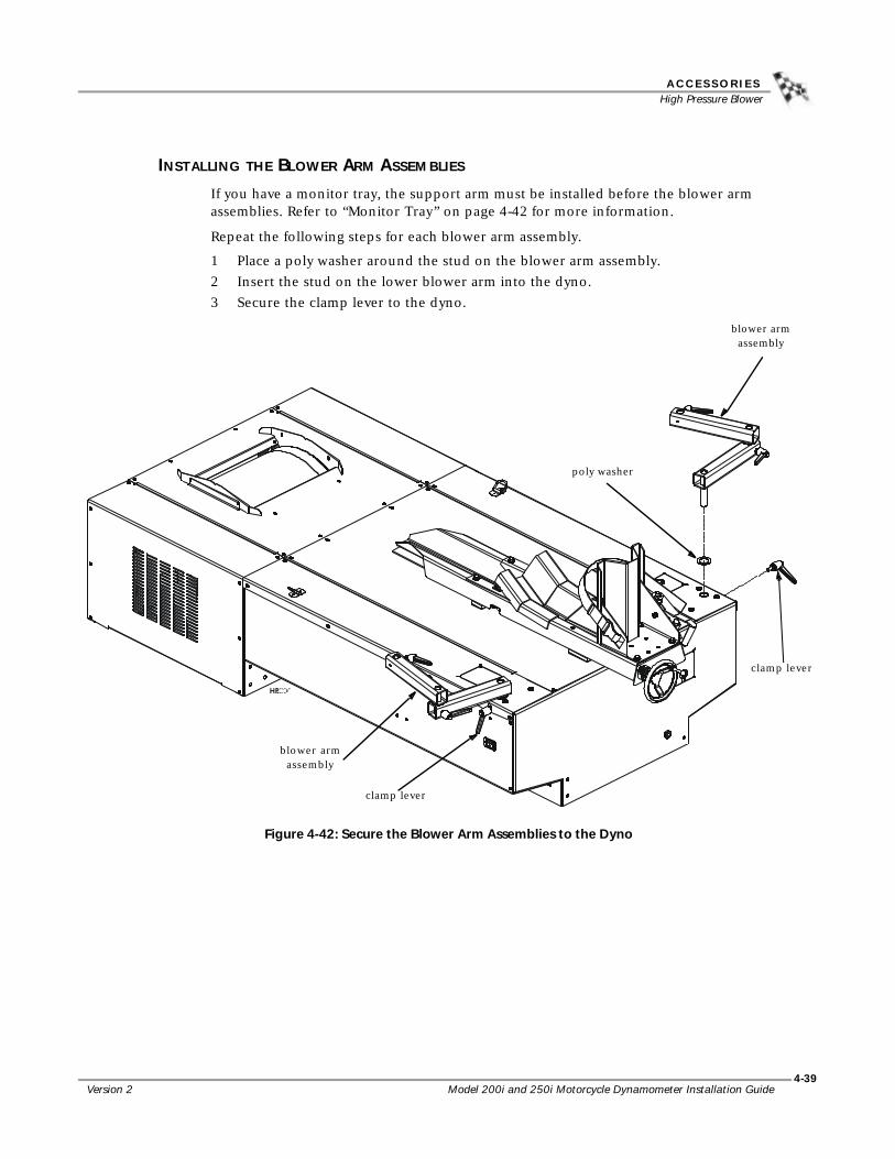
A C C E S S O R I E SHigh Pressure Blower
Version 2 Model 200i and 250i Motorcycle Dynamometer Installation Guide
4-39
INSTALLING THE BLOWER ARM ASSEMBLIES
If you have a monitor tray, the support arm must be installed before the blower arm assemblies. Refer to “Monitor Tray” on page 4-42 for more information.
Repeat the following steps for each blower arm assembly.
1 Place a poly washer around the stud on the blower arm assembly.2 Insert the stud on the lower blower arm into the dyno.3 Secure the clamp lever to the dyno.
Figure 4-42: Secure the Blower Arm Assemblies to the Dyno
clamp lever
poly washer
blower arm assembly
blower arm assembly
clamp lever

Model 200i and 250i Motorcycle Dynamometer Installation Guide
C H A P T E R 4High Pressure Blower
4-40
INSTALLING THE HIGH PRESSURE BLOWER ASSEMBLIES
Repeat the following steps for each blower assembly.
1 Place a poly washer around the stud on the blower assembly.2 Insert the stud on the blower assembly into the blower arm.
Figure 4-43: Install the Blower Assembly
blower assembly
poly washer
blower arm

A C C E S S O R I E SHigh Pressure Blower
Version 2 Model 200i and 250i Motorcycle Dynamometer Installation Guide
4-41
POWER HOOKUP
Each blower has it’s own power cord and will plug directly into the dyno chassis.
1 Plug the power cord from the blower into the power source located on the dyno chassis.
2 Activate the blowers using the switches on the on the blower motor. The blowers are independent of one another; each blower can be turned on and off individually.
Risk of injury. Eye protection required. Be aware of debris from blowers. Be sure the blowers are free and clear of any obstruction. The blowers can run at any time once the cord is plugged into a power source.
Figure 4-44: Power Hookup
power cord from blower
plug into dyno chassis
power cord from blower

Model 200i and 250i Motorcycle Dynamometer Installation Guide
C H A P T E R 4Monitor Tray
4-42
. . . . . . . . . . . . . . . . . . . . . . . . . . . . . . . . . . .MONITOR TRAY
This articulated arm and platform supports the monitor, keyboard, and mouse in a convenient position for operation while seated on the motorcycle. The support arm can be mounted on either side of the dynamometer.
PARTS LIST
The following table lists all of the parts included in the Monitor Stand Installation kit. Check your kit against the parts listed to make sure you have received all of the parts. If any part is missing, contact Dynojet Technical Support.
part number description quantity21229300 Monitor Arm Tray 132391064 Bushing, 1" x 2", 10 Gauge, Stl 335521420 Plastic Cap, 1-3/4" x 1/2", Black 436701100 Nut, 1/2-13, Hex 236801253 Screw, 1/2-13 x 1-1/2", Sh-Cap 236932100 Washer, 3/8", Splitlock, Stl 136942100 Washer, 1/2", Splitlock, Stl 236943100 Washer, 1/2", Flat, Stl 461329100 Monitor Arm 2

A C C E S S O R I E SMonitor Tray
Version 2 Model 200i and 250i Motorcycle Dynamometer Installation Guide
4-43
INSTALLING THE SUPPORT ARM AND TRAY
The support arm and monitor tray may be installed on either side of your dyno.
1 Remove the four 3/8-16 x 1/2-inch button-head flange screws from the dyno where you plan to install the support arm.
2 Using an allen wrench, secure the support arm to the dyno frame with four 3/8-16 x 1/2-inch button-head flange screws you removed earlier.
3 Place a poly washer around the pin of the first arm and insert the arm into the support arm.
4 Place a poly washer around the pin of the second arm and insert the arm into the first arm.
5 Place a poly washer around the pin of the tray and insert the tray into the second arm.
6 Insert a plastic cap in both ends of each arm.7 Check for clearance between the monitor arm and motorcycle, walls, ceiling, etc.
Note: Dynojet does not recommend placing the computer CPU on the monitor/keyboard tray since vibration can cause damage to the computer.
Figure 4-45: Install the Support Arm and Monitor Tray
second arm
poly washer
first arm
monitor tray
support arm
poly washer
poly washer

Model 200i and 250i Motorcycle Dynamometer Installation Guide
C H A P T E R 4Power Carriage
4-44
. . . . . . . . . . . . . . . . . . . . . . . . . . . . . . . . . . .POWER CARRIAGE
The power carriage replaces the standard hand crank with an electrically powered tire carriage allowing you to easily adjust for various wheel base distances with the press of a button. This option is ideal for dynos that are recessed where the hand crank is difficult to access. The power carriage will also reduce the time spent making adjustments for various length motorcycles.
The power carriage motor is preset to be installed with the carriage screwed in all the way. Do not run the motor prior to installing it on your dyno.
To prevent possible injury, place the breaker inside the power distribution enclosure to the off position and unplug the dyno. Refer to Figure 1-4 for breaker location.
PARTS LIST
The following table lists all of the parts included in the Power Carriage Installation kit. Check your kit against the parts listed to make sure you have received all of the parts. If any part is missing, contact Dynojet Technical Support.
REMOVING THE HAND CRANK
1 Remove the hand crank from the tire carriage.1a Screw the carriage all the way in.
1b Loosen the set screw on the hand crank and remove the hand crank.
Figure 4-46: Remove the Hand Crank
part number description quantity36561284 Screw, 1/4-20 x 3/4” Button-Head 236561670 Bolt, 1/4-20 x 1”, Hex 236912100 Washer, 1/4”, Splitlock, STL 2
hand crank
set screw

A C C E S S O R I E SPower Carriage
Version 2 Model 200i and 250i Motorcycle Dynamometer Installation Guide
4-45
2 Using a 5/32-inch allen wrench, loosen the two set screws in the lock collar and remove it from the screw shaft.
3 Using a 7/16-inch wrench, remove the two bolts securing the flange bearing.4 Pry the flange bearing from the carriage screw shaft with a flat screwdriver and set
aside.Note: Clean the shaft with a fine grit emery cloth to remove any remaining thread lock residue. This will make it easier to slide the motor assembly and flange bearing on the shaft.
Figure 4-47: Remove the Flange Bearing
INSTALLING THE POWER CARRIAGE
1 Remove the two button-head screws securing the aluminum cover to the motor mount assembly and set aside.
Figure 4-48: Remove the Aluminum Cover
set screw on lock collar(only one visible)
bolts
shaft
flange bearing
button-head screws
aluminum cover
motor mount assembly

Model 200i and 250i Motorcycle Dynamometer Installation Guide
C H A P T E R 4Power Carriage
4-46
2 Slide the motor mount assembly and flange bearing, removed earlier, over the screw shaft. Make sure the flex coupling is on the shaft.Note: The flange bearing must be facing as shown in Figure 4-49 so the grease zerk is accessible.
3 Secure the motor mount assembly and flange bearing to the carriage using two 1/4 x 1-inch bolts and lock washers.Note: Dynojet recommends using a 1/4-inch ratchet drive with universal joint and a 7/16-inch shallow socket to secure the flange bearing bolts.
4 Using a 1/8-inch allen wrench, tighten the flex coupling set screw.
Figure 4-49: Install the Motor Mount Assembly
motor mount assembly
screw shaft
flex coupling set screw
flange bearing bolts
grease zerk
flex coupling
flange bearing

A C C E S S O R I E SPower Carriage
Version 2 Model 200i and 250i Motorcycle Dynamometer Installation Guide
4-47
5 Secure the aluminum cover with the two screws you removed earlier.6 Plug the power cord into a 120 volt power source.
Note: For European and 240 volt applications, a step down transformer must be used to provide 120 volts.
7 Using the pendant, move the power carriage through the entire range of motion making sure there is no binding or jamming.Note: When operating the power carriage with a bike on the dyno, make sure the bike is in neutral.
Figure 4-50: Power Carriage Secured to Dyno
pendant
aluminum cover

Model 200i and 250i Motorcycle Dynamometer Installation Guide
C H A P T E R 4Safety Switch Installation
4-48
. . . . . . . . . . . . . . . . . . . . . . . . . . . . . . . . . . .SAFETY SWITCH INSTALLATION
The safety switch requires the air brake to work. This switch is located on the dyno room door; when the door is open, the air brake is locked. This prevents the dyno from being used when the door is open.
1 Remove the cover on the wire junction box.2 Loosen the set screws that hold the jumper wire, and then remove the jumper
wire.3 Route the yellow and black wires from the safety switch through the dyno to the
wire junction box.3a Route the wires through one of the three access panels (one at the front of
the dyno and two on the top cover, refer to Figure 2-5 for panel locations).3b Continue routing the wires through the dyno and through any of the three
access holes in the drum bulkhead (refer to Figure 2-4 for access hole locations).
4 Feed the yellow and black wires through the side of the wire junction box.5 The wires from the switch are to be installed across where the jumper lead was
removed. Wire so the yellow lead from the switch lines up with the yellow lead on the bottom of the terminal strip. Wire the black lead from the switch so that it lines up the black wire on the bottom of the terminal strip.
6 The safety switch needs to be mounted at the entry of the dyno cell. The switch is “open” when the plunger is out, and “closed” when the plunger is depressed. Mount the switch on the dyno cell door / access gate so that the switch is closed when the door is closed. When the door is opened, the switch will “open” and the the dynamometer will stop running.
Figure 4-51: Wiring the Safety Switch
remove jumper
black leadyellow lead

Model 200i and 250i Motorcycle Dynamometer Installation Guide5-1
C H A P T E R
5BASIC DYNO OPERATION
This chapter includes instructions for basic dyno operation. For more detailed instructions, refer to the WinPEP 7 User Guide. This manual can be found on your WinPEP CD or at www.dynojet.com/manuals.shtml.
This chapter is divided into the following categories:
• Loading the Bike, page 5-2
• Using the Starter, page 5-4
• Using the Dyno, page 5-4
• Preventative Maintenance, page 5-4

Model 200i and 250i Motorcycle Dynamometer Installation Guide
C H A P T E R 5Loading the Bike
5-2
. . . . . . . . . . . . . . . . . . . . . . . . . . . . . . . . . . .LOADING THE BIKE
Use the following steps to load a motorcycle on the dyno.
Keep the motorcycle balanced while driving on and off the dyno.
Risk of injury. Always wear proper eye and ear protection when operating the dyno.
1 Load the bike on the dyno.2 Place the bike on the dyno so the front tire is in the tire stop.3 Strap the front wheel to the tire stop and tighten.
Never perform a dyno run if the tire strap is not in place or is damaged.
4 Turn the carriage screw handle until the rear axle is aligned with the center of the drum.
5 With the motorcycle in neutral, align the wheel in the center of the knurl by pressing the dyno starter switch.
Figure 5-1: Align the Wheel and Axle
tire stop
tire strap
adjust carriage to align rear axle with drum
center drive axle on dyno drum

B A S I C D Y N O O P E R A T I O NLoading the Bike
Version 2 Model 200i and 250i Motorcycle Dynamometer Installation Guide
5-3
6 Attach the tie-down straps from a solid place on the bike to the tie-downs on the dyno or the ground hook locations (refer to page 2-21). Position the straps to allow proper clearance for the brake pedal, the shift lever and the exhaust pipes. For best results, hook the straps at the rear of the bike so they pull down and forward.
7 Sit on the bike with your feet on the pegs. Remove the slack from the straps. Gently shift your weight from side to side while tightening the straps, being careful to not overtighten the straps. The straps are used to stabilize the bike. They should not add any additional weight to the bike.
Never perform a dyno run if the tie-down straps are not in place or they are damaged.
Figure 5-2: Attach the Tie-down Straps
tie-down tie-down strap

Model 200i and 250i Motorcycle Dynamometer Installation Guide
C H A P T E R 5Using the Starter
5-4
. . . . . . . . . . . . . . . . . . . . . . . . . . . . . . . . . . .USING THE STARTER
The starter allows you to use the momentum of the drum to start motorcycles that are not equipped with an on-board starting system.
1 Make sure the motorcycle is in neutral or the clutch is in.2 Press and hold the starter button to spin the drum. Hold the starter button until
the drum reaches maximum speed then release the starter button.3 Use the momentum of the drum to start the bike.
. . . . . . . . . . . . . . . . . . . . . . . . . . . . . . . . . . .USING THE DYNO
With the bike properly loaded and secured, you are now ready to begin making runs and using your dyno. From here you will need to refer to your WinPEP 7 User Guide for detailed instructions on making and graphing runs.
The WinPEP 7 User Guide can be found on your WinPEP CD or at www.dynojet.com/manuals.shtml.
. . . . . . . . . . . . . . . . . . . . . . . . . . . . . . . . . . .PREVENTATIVE MAINTENANCE
To maintain proper dynamometer operation, Dynojet recommends you make routine checks of the dyno.
• Drum—keep the drum clean and keep all objects clear of the drum.
• Brake Pads—check the brake pad clearance regularly. Change the brake pads when they are worn to less than 0.060 inch thick.
• Air Pump Filter—clean the filter daily or more often depending on usage. Change the filter when necessary.
• Carriage Slide—keep the carriage slide and screw clean and lightly lubricated.

Model 200i and 250i Motorcycle Dynamometer Installation GuideA-1
A P P E N D I X
ARED HEAD ANCHOR INSTALLATION
This appendix contains instructions for installing the Red Head Multi-Set™II Anchors. The anchors will be used to secure the dyno to concrete. To ensure safety and accuracy in the procedures, perform the procedures as they are described. Be sure to read and understand the warnings included in this appendix.
WARNINGS
Always wear safety glasses and other necessary protective devices or apparel when installing or working with anchors.
ITW Ramset/Red Head Multi-Set II Anchors are designed to operate properly only when installed with ITW Ramset/Red Head brand Setting Tools.
The use of a 24 to 40 ounce hammer is recommended for expanding Multi-Set II anchors.
The use of carbide drill bits manufactured with ANSI B94. 12-77 drill bit diameter requirements is recommended for installation of this anchor.
Not recommended for use in lightweight masonry material such as block or brick.
Use of core drills is not recommended to drill holes for use with this anchor.
Not recommended for use in new concrete which has not had sufficient time to cure.
Anchor spacing and edge distance requirements (anchor installation locations) are the responsibility of the engineer of record.
CONTACT INFORMATION FOR ITW RAMSET/RED HEADContact ITW Ramset/Red Head at 1-630-350-0370, or 1300 North Michael Drive, Wood Dale, IL 60191.

Model 200i and 250i Motorcycle Dynamometer Installation Guide
A P P E N D I X AInstallation
A-2
. . . . . . . . . . . . . . . . . . . . . . . . . . . . . . . . . . .INSTALLATION
Use the table below to determine the catalog number, drill bit size, minimum hole depth, and setting tool catalog number.
Use the following instructions to install the Red Head anchors.
1 Drill the hole in the concrete the same outside diameter as the anchor being used to any depth exceeding minimum embedment.
Figure A-1: Red Head Anchor—Drill the Hole
2 Insert the anchor.
Figure A-2: Red Head Anchor—Insert the Anchor
catalog number drill bit size minimum hole depthsetting tool catalog number
Carbon SteelRM-38/RL-38 (9.5 mm)
1/2-inch 1 5/8-inch (41.2 mm) RT-138
anchor

R E D H E A D A N C H O R I N S T A L L A T I O NInstallation
Version 2 Model 200i and 250i Motorcycle Dynamometer Installation Guide
A-3
3 Using a hammer, drive the anchor flush with the surface of the concrete, or below the surface if the hole depth exceeds minimum embedment.
Figure A-3: Red Head Anchor—Drive the Anchor Flush
4 Using a hammer, expand the anchor with the setting tool. The anchor is properly expanded when the shoulder of the setting tool is flush with the top of the anchor.Note: Use only Ramset/Red Head setting tools to insure proper installtion.
Figure A-4: Red Head Anchor—Expand the Anchor
setting tool


Model 200i and 250i Motorcycle Dynamometer Installation GuideB-1
A P P E N D I X
BPOWER REQUIREMENTS—EXCLUDING
NORTH AMERICA
This appendix contains the power requirements and instructions for all locations excluding North America dyno installations. Refer to page 1-8 for power requirements and instructions for North America and Japan. To ensure safety and accuracy in the procedures, perform the procedures as they are described.

Model 200i and 250i Motorcycle Dynamometer Installation Guide
A P P E N D I X BPower Requirements and Installation
B-2
. . . . . . . . . . . . . . . . . . . . . . . . . . . . . . . . . . .POWER REQUIREMENTS AND INSTALLATION
The model 200i and 250i dynamometers (excluding North America and Japan) require a dedicated wall receptacle which must be wired for operation and is included with the dyno. The dyno is equipped with a ten foot power cord with a three-pin IEC plug pre-wired on the end. The power cord is located at the front of the dyno. Refer to Figure 1-4 for the location of the power cord.
The dedicated wall receptacle is a three-pin IEC grounded 30A type and must be wired in accordance with local building codes and requirements. Installation may require a licensed electrician to conform to applicable safety standards.
Local and national electrical codes will require that the box containing the receptacle is grounded.
• This circuit should have a dedicated 30A double pole circuit breaker.• The dyno should be the only device connected to this circuit.• It may be necessary to install a delayed trip breaker due to the inrush current
drawn by the high pressure blowers.
INSTALLING THE WALL RECEPTACLE
The wall receptacle is a single 240 volt 30A dedicated circuit with a ground.
The cable carrying the power to this receptacle should be 4.0 mm2 (ten gauge) or larger. Check with local building codes for the correct size.
1 Connect one of the 240V legs to the N terminal (white).2 Connect the other 240V leg to the L terminal (no color).3 Connect the ground conductor to the green terminal.
Figure B-1: Wiring the Wall Receptacle
N terminal (white)
L terminal
ground terminal (green)

P O W E R R E Q U I R E M E N T S — E X C L U D I N G N O R T H A M E R I C APower Requirements and Installation
Version 2 Model 200i and 250i Motorcycle Dynamometer Installation Guide
B-3
TESTING FOR CORRECT VOLTAGES
You must test the receptacle for proper voltages before the dyno is connected to the outlet.
Using a voltmeter that is capable of measuring AC voltage, measure between the points listed below and verify that the correct voltages are present.
Figure B-2: Testing the Wall Receptacle
CONNECTING THE DYNO
1 Turn off the main circuit breaker for the dyno. This is the large breaker in the center of the power distribution assembly behind the door on the left hand side of the dyno. Refer to Figure 1-4 for breaker location. Off is the down position.
2 Once you verify the voltages on the receptacle, connect the dyno to the receptacle.
3 Connect the high pressure blowers to the dyno. For more information on installing and connecting the blowers, refer to page 4-38.
4 Turn on the main dyno breaker. Refer to Figure 1-4 for breaker location.5 Test the blowers for operation.6 Turn on the dyno electronics and verify operation.
probe 1 probe 2 desired voltage measurement1 3 220V to 250V2 box <5V
1
2
3


Model 200i and 250i Motorcycle Dynamometer Installation GuideIndex-i
INDEX
Aaccessing dyno electronics 3-6accessories
air brake 4-4–4-9air pump and filter assembly 4-11–4-17eddy current brake 4-18–4-29extended carriage 4-30–4-37high pressure blower 4-38–4-41monitor tray 4-42–4-43power carriage 4-44–4-47safety switch 4-48
air brake 4-4–4-9adjustments and tests 4-5brake pads 4-5–4-9parts list 4-4
air pump and filter assembly 4-11–4-17cleaning the filter 4-15installation 4-12–4-15parts list 4-12pump head maintenance 4-16sensor 4-15
anchor placementdyno 2-13eddy current brake 4-27
atmospheric sensing module 3-2
Bbattery 1-10, 2-15battery hazards vibelleville washers 2-10, 4-35brake pads 4-5–4-9breakout board, wiring 4-26
control cable 4-26jumpers 4-26temperature sensor 4-26
Ccomputer cable, routing 2-6computer specifications 1-10control cable
routing 2-7wiring 4-26
conventions 1-3coupler 4-23CPU module 3-5crate
remove dyno 2-12unpacking dyno 2-2–2-13unpacking eddy current brake 4-19
Ddimensions 1-6disclaimers vdocument part number 1-1drum covers
removing 4-2replacing 2-16, 4-2
dynamometer input/output module 3-4dyno electronics
accessing 3-6atmospheric sensing module 3-2CPU module 3-5dynamometer input/output module 3-4RPM module 3-3
Eeddy current brake 4-18–4-29
coupler 4-23installation 4-22–4-28parts list 4-18right side installation 4-20routing cables 4-25theta controller fuses 4-29unpacking 4-19wiring breakout board 4-26
electrostatic discharge vi

Model 200i and 250i Motorcycle Dynamometer Installation Guide
I N D E X
Index-ii
ESD precautions viexhaust extraction bottles 4-14extended carriage 4-30–4-37
belleville washers 4-35installation 4-34nut block 4-31, 4-33parts list 4-30remove tire carriage 4-31screw support bracket 4-35shims 4-33support bracket 4-32tire lock 4-37tire stop 4-36
Ffilter assembly 4-13
cleaning 4-15
Ggrease zerk 4-46ground hooks 2-21grounding, equipment v
Hhand crank 2-9hazards viiheight 1-5high pressure blower 4-38–4-41
installing arms 4-39installing blowers 4-40parts list 4-38power hookup 4-41
IIndustrial Noise Control, Inc. 1-4installation requirements
power 1-8, B-2
Kknurl 5-2
Llength 1-5lifting eyes
dyno 2-12eddy current brake 4-21
load bike 5-2–5-3
Mmanuals, finding on WinPEP cd 4-1model 200i 1-11model 250i 1-12monitor tray 4-42–4-43
parts list 4-42support arm 2-2, 4-43
motor mount assembly 4-46
Nnut block 2-8, 4-31, 4-33
Ppendant cable, routing 2-6pickup card 2-14power 1-8, B-2
connecting the dyno 1-9, B-3installation 1-8, B-2requirements 1-8, B-2testing voltages 1-9, B-3
power carriage 4-44–4-47flange bearing 4-45grease zerk 4-46hand crank 4-44motor mount assembly 4-46parts list 4-44power requirements 4-47
power requirements 1-8, B-2power carriage 4-47
preventative maintenance 5-4pump assembly 4-13pump head maintenance 4-16
Rramp bracket 2-18–2-20red head anchor
contact information A-1installation A-2setting tool A-3warnings A-1
requirements 1-8–1-10, B-2–B-3battery 1-10computer specifications 1-10phone and internet access 1-10tie down straps 1-10
routing cablesbrake power 4-25computer 2-6control 2-7, 4-25pendant 2-6starter 2-6temperature sensor 4-25
RPM module 3-3
Ssafety switch 4-48screw support bracket 2-10
extended carriage 4-35sensor, air pump 4-15setting tool A-3specifications 1-5starter 5-4starter cable, routing 2-6support arm 4-43
remove from crate 2-2

Version 2 Model 200i and 250i Motorcycle Dynamometer Installation Guide
Index- iii
Ttechnical support 1-3testing voltages 1-9, B-3theta controller
installation 2-7replace fuses 4-29route control cable 2-7
tire carriage 5-2belleville washers 2-10hand crank 2-9installation 2-8–2-11nut block 2-8remove from crate 2-2screw support bracket 2-10tire lock 2-11tire stop 2-11
tire lock 2-11, 4-37tire stop 2-11, 4-36
Wwarnings vweight 1-5width 1-5WinPEP
finding manuals on 4-1using the dyno 5-4
wiring breakout boardcontrol cable 4-26jumpers 4-26temperature sensor cable 4-26
Yyour dyno room 1-3
cooling fan 1-3equalizer box 1-3exhaust extraction 1-4noise control 1-4