Embed Size (px)
Citation preview

2-POST-LIFTS
Operating and installation instruction
Consul 2.30 - H264 Consul 2.30 EL - H300 Consul 2.35 - H265 Consul 2.35 EL - H301 Consul 2.40 EL - H327 Consul 2.60 - H342 Consul 2.60 EL - H331 Consul 2.25 RMC - H339 Prolift 3003 GA - H325 Prolift 2.30 EL - H354 Prolift 2.40 EL - H355
Vers
ion
1.0
St
and:
Jul
i 200
4
Te
Consul Werkstattausrüstung GmbH – Daimlerstraße 1 - 58553 Halver l.: (02353) 7009-0 - Telefax: (02353) 12515 - E-mail: [email protected]

OPERATING & INSTALLATION INSTRUCTION 2-POST-LIFT
Contents EC Declaration of Conformity .......................................................................................................................... 3 Service memorandum standard fundaments .................................................................................................. 5 Foreword.......................................................................................................................................................... 6 Safety devices ................................................................................................................................................. 6 Practical use with the post lifts ........................................................................................................................ 8 Testing of Lifts ................................................................................................................................................. 9 Technical details H300 / H301 / H327 / H339 / H331 / H354 / H355 ............................................................ 10 Technical details H264 / H265 / H342 / H325 ............................................................................................... 18 Production description H300/H301/H339/H331/H327/H354/H355 ............................................................... 24 Production description H264/H265/H342/H325 ............................................................................................ 25 Foundation..................................................................................................................................................... 26 Floor fixing for lifts til 4 to ............................................................................................................................... 47 Foundation for lifts til 4 to .............................................................................................................................. 28 Floor fixing for lifts over 4 to EL-Version ....................................................................................................... 29 Floor fixing for chain liftsH264/H265 ............................................................................................................. 31 Foundation chain lifts H264/H265 ................................................................................................................. 32 Floor fixing H342^.......................................................................................................................................... 33 Installation and Commissioning of chainlift H300/H301/H339/H327/H321................................................... 34 Installation and Commissioning of chainlift H264/H265/H325 ...................................................................... 36 Chain break switch H264/H265/H325 ........................................................................................................... 38 Installation and Commissioning of chainlift H342.......................................................................................... 39 Switch again chain break H342..................................................................................................................... 41 Load nut failure .............................................................................................................................................. 43 Load bearing nut testing ................................................................................................................................ 44 Description of the main board SGMX2.......................................................................................................... 45 Faults and Causes......................................................................................................................................... 50 Emergency lowering II ................................................................................................................................... 51 Emergency lowering I .................................................................................................................................... 52 Maintenance and Service .............................................................................................................................. 53 Automatic lubrication system......................................................................................................................... 54 Manual arm lock override .............................................................................................................................. 56 Manual arm lock for 6to lifts........................................................................................................................... 57 Lifting plate with pin bushin ........................................................................................................................... 58 Lifting plate lift 6 to......................................................................................................................................... 59 Control unit with rotary reversing switch (36953.8) ....................................................................................... 60 Control unit with rotary reversing button (36953.8) ....................................................................................... 61 Control with push-buttons 38032.9................................................................................................................ 62 Control with push-buttons 380329................................................................................................................. 63 Control unit H325 Prolift 3003 GA ................................................................................................................. 64 Parts list control unit H325 Prolift 3003 GA................................................................................................... 65 Electric diagram for chain lifts H264/H265 .................................................................................................... 66 Electric diagram H342 ................................................................................................................................... 67 Electric diagram H325 ................................................................................................................................... 68 Electrical diagram with rotary reversing switch ............................................................................................. 69 Electrical diagram with push-buttons............................................................................................................. 70 Certificates..................................................................................................................................................... 71
Page 2
OPERATING & INSTALLATION INSTRUCTION 2-POST-LIFT
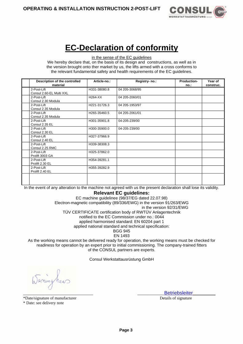
EC-Declaration of conformity in the sense of the EC guidelines
We hereby declare that, on the basis of its design and constructions, as well as in the version brought onto ther market by us, the lifts armed with a cross conforms to
the relevant fundamental safety and health requirements of the EC guidelines.
Description of the controlled material
Article-no.: Registry- no.: Production- no.:
Year of construc.
2-Post-Lift Consul 2.60-EL Multi XXL
H331-38080.8 04 205-3068/95
2-Post-Lift Consul 2.30 Modula
H264-XX 04 205-2060/01
2-Post-Lift Consul 2.35 Modula
H221-31726.3 04 205-1953/97
2-Post-Lift Consul 2.35 Modula
H265-35460.5
04 205-2061/01
2-Post-Lift Consul 2.35 EL
H301-35901.8 04-205-239/00
2-Post-Lift Consul 2.30 EL
H300-35900.0 04-205-239/00
2-Post-Lift Consul 2.40 EL
H327-37966.9
2-Post-Lift Consul 2.25 RMC
H339-38308.3
2-Post-Lift Prolift 3003 GA
H325-37862.0
2-Post-Lift Prolift 2.30 EL
H354-39281.1
2-Post-Lift Prolift 2.40 EL
H355-39282.9
In the event of any alteration to the machine not agreed with us the present declaration shall lose its validity. Relevant EC guidelines:
EC machine guidelinee (98/37/EG dated 22.07.98) Electron-magnetic compatibility (89/336/EWG) in the version 91/263/EWG in the version 92/31/EWG
TÜV CERTIFICATE certification body of RWTÜV Anlagentechnik notified to the EC Commission under no.: 0044 applied harmonised standard: EN 60204 part 1
applied national standard and technical specification: BGG 945 EN 1493
As the working means cannot be delivered ready for operation, the working means must be checked for readiness for operation by an expert prior to initial commissioning. The company-trained fitters
of the CONSUL partners are experts.
Consul Werkstattausrüstung GmbH
__________________________________ _____________Betriebsleiter___________ *Date/signature of manufacturer Details of signature * Date: see delivery note
Page 3

OPERATING & INSTALLATION INSTRUCTION 2-POST-LIFT
Service memorandum scope of performance vehicle lifts 1. Delivery by freight forwarder invoicing with normal lump-sum freight charge: A forklift truck must be made available at short notice. Weight of the lifts approx. 650 – 2700 kg, depending on lift type. 2. Delivery by truck with loading tailboard invoicing with increase lump-sum freight charge: Unloading assistance must be provided at short noticeWeight of the lifts aprrox. 650 – 2700 kg, depending on lift type. 3. Preparations for setting up Prior to setting up the lifts the following work must be arranged by the operator: ♦ Preparation of the fundament (see standard fundaments). ♦ Laying of electrical connection lead to the place of setting up. ♦ Laying of compressed air connection to the place of setting up (if necessary). ♦ Transport of the lift to the place of setting up. 4. Minimum requirements on fundaments The surface of the fundaments must be level and horizontal for all lifts. The underground must conform to the general guidelines for building ground (DIN 1054).For lifts set up in the open air, the underground must be frost-proof. When setting up on ceilings, an individual case check must be made with the statical calculations engineer. Lifts can be anchored with dowels, shear connectors or with M12 through bolts or threaded rods, minimum strength 8.8 and washers – see also BGG 945 -. 5. Performances of our customer service section The Consul service section or Consul authorised partner takes on the setting up of the lift with the following performances: - Dowelling to the floor. - Assembly of the lift. For setting-up of the lift, auxiliary personnel, as well as technical auxiliary means must be provided at short notice. - Electrical functional check and trial run without final mains connection that must be carried out by a local specialist. - Without final connection cablin with bei EL 2 Post-lifts, if no cable bridge is envisaged. - Safety acceptance with entry in the test book. - short instruction. 6. Average time requirement (prerequisite is the fulfillment of the above mentioned conditions) : Single Post Lift - approx. 3 hours working time 2-Post-Lifts - approx. 4 hours working time (with base frame approx. 3 hours) With the 2-Post-Lifts of the EL models series, the electrical connection cables are only assembled with simultaneous assembly of a cable boom (accessory). Otherwise these cables are laid by the operator. 4-Post-Lifts: - without after-lift approx 7 hours working time - with after-lift approx. 9 hours working time Short lifts approx. 2 hours working time Pantograph lifts approx. 9 hours working time
Page 4

OPERATING & INSTALLATION INSTRUCTION 2-POST-LIFT
If the lift is set up by the operator himself, the attached assembly and operating instructions must be observed. Subsequently the lift must be subjected to safety acceptance by a Consul customer service section. This includes the following performances:
Electrical functional check and trial run. according to BGG 945 examination of the individual structural components. Entry in the check list. Short instruction.
-If these points are not observed, the guarantee expires.- 7. Annual expert check (UVV) In addition to the check prior to the initial commissioning of the lift by our customer service section, the official regulations demand at least one safety acceptance per year experts. Our customer service section will be pleased to submit you a quotation for a maintenance contract. 8. Assembly cost rates and invoicing The performances of the customer service section stated are invoiced in accordance with the respectively applicable terms and conditions of assembly, hourly rates and lump-sum travelling amounts. Securing material is not included in the scope of delivery of the lifts. 9. Guarantee On the basis of the fact that lifts must satisfy hight safety requirements for the protection of the persons working on them, we draw your attention to the fact that we must tie the guarantee entitlement of the operator to the correctly performed safety acceptance and entry of this in the check list. Always uses original spare parts. The use of any other parts invalidates the design permit and all claims under warranty.
Service memorandum standard fundaments Individual fundaments: Concrete floor
(hall floor)
Type: Fundament dimensions Fundament characteristics
Length in direction of travel
Width in direction of travel
Min, thickness without floor covering
Quality of concrete
Anchoring depth dowels *
Consul 2.25 RMC 150 cm 350 cm 15 cm B25 11 cm Consul 2.30 Modula 120 cm 100 cm 21 cm B 25 13 cm Consul 2.30 Modula EL 120 cm 100 cm 21 cm B 25 11 cm Consul 2.35 Modula 120 cm 100 cm 21 cm B 25 13 cm Consul 2.35 Modula EL 120 cm 100 cm 21 cm B 25 11 cm Consul 2.40 Modula EL 120 cm 100 cm 21 cm B 25 13 cm Consul 2.60 2M 150 cm 350 cm 21 cm B 25 10 cm Consul 2.60 2M GF/EL 150 cm 150 cm 21 cm B 25 10 cm Prolift 3003 GA 120 cm 100 cm 18 cm B 25 13 cm Prolift 2.30 EL 120 cm 100 cm 21 cm B 25 11 cm Prolift 2.40 EL 120 cm 100 cm 21 cm B 25 13 cm The setting up of the lifts is only admissible and will only be carried out if the minimum requirement on the fundaments indicated are fulfilled at the place of setting up. see page 6 * in the respect the information of the dowel manufacturers is binding! subject to change without prior notice!
Page 5

OPERATING & INSTALLATION INSTRUCTION 2-POST-LIFT
Foreword Your Consul lift has been design-tested in its basic concept, it offers you maximum economic efficiency and safety. It is up to you to make use of these advantages. A prerequisite for this is correct operation, perfect maintenance and good care of the lift. Please read these operating instructions carefully. They provide you with all necessary data and show how simple it is to keep your lift ready for use at all times. Your Consul lift is only designed to raise automobiles or vehicles whose total weight does not exceed the lifts’s maximum permitted load capacity and whose specified support points are within the lift’s support area. All 4 locating points have to be used. Your Consul lift is designed to raise motor vehicles. The carrying of people is not permitted. When using the lift in lacquering plants or rooms in which a large amount of work is carried out with solvent-containing materials, pay attention to the risk of explosion. In its standard form the drive is not protected against explosion.
Safety devices
Your lift is equiped with several safety devices, to ensure workers safety, if the list is used according to this manual. Please take care of this safety devices, when installing the lift and check them after any case of failure. Only trained service people are allowed to repair this lift. Only original parts are to be used for repair. If third parts equipment is used for repair, the CE certificate of conformity will be avoided. In accordance with the regulations regarding the operation of lifts, lift devices must be checked for their operational safety by an expert at the latest after one year (BGG 945). The control has to be notified in the check list. In this respect please pay attention to ensuring that only company-trained experts, who have been instructed in the function of lifts and who are in possession of a certificate from the manufacturing company, check and accept your lift.
Page 6

OPERATING & INSTALLATION INSTRUCTION 2-POST-LIFT
Attention! Important instructions for assembling the 2-Post-Lift! 1. The assembly should be carried out by qualified staff in accordance with the construction and operating
instructions (otherwise the guarantee will be invalidated). 2. Check that all parts have been delivered before commencing assembly. 3. Final insulation checks must be carried out according to VDE instruction 0100. 4. Test instructions are to be complied with, in accordance with BGG945. 5. Instructions for the foundations of the lift must be strictly observed. 6. Carefully ensure that the drive shaft is parallel to the spindle shaft when assembling the lift. To adjust
this the two flat head screws can be loosened, then retightened. 7. Check the locking mechanism of the swivel arm, then ensure that the bolt is vertical and parallel to the
front of the column. 8. Only ever fill the automatic lubrication system with original Consul Spindle Oil. 9. The lift is preprogrammed in the factory and must be adjusted to local conditions. Check that the foot
protection facility is at the correct height (compulsory stop and signal tone). 10. Be aware of the alignment (outward lean) of the columns. 11. Check the gap between the steering frame and the tension band (correst and grease the back of the
tension band when necessary). 12. The self-securing swivel arm screws only reach complete tightness after 24 hours (check for a gap of 1
to 2 mm between the screw head and the swivel arm bearing) 13. Check the adjustment of the chain break switch on lifts with chain synchronization. 14. After the first test run without a load, a test run with a nominal load must be carried out. 15. Observe maintenance schedule (swivel arms, spindles, bearings of turntable). 16. Only lift using all 4 swinging arms and only at the lifting points permitted by the manufacturer. Consul Werkstattausrüstung GmbH Daimlerstr. 1 D-58553 Halver Telefon: ++49 (0)2353-7009-0 Telefax: ++49 (0)2353-12515
E-Mail: [email protected]
Page 7

OPERATING & INSTALLATION INSTRUCTION 2-POST-LIFT
Practical use with the post-lifts Switch the main switch to the " Ein " (on) position. Turn the control knob to move the lift in the direction indicated by the arrows. On release of the control knob it returns automatically to the “off” position. Operating the lift is only permitted by authorised persons! According to the regulations for prevention of accidents, persons under the age of 18 are not permitted to operate the lift without supervision. The lift is designed only as a vehicle lift, it should not be used for other purposes. See instruction on the lift column. If there are any faults with the lift, turn off electricity, make safe, secure against unauthorised use and contact the Consul Service Section. See the operation label on the lift column! Before lifting or lowering a vehicle check that nobody is in danger, that nothing is leaning against the vehicle and no obstacles are underneath it. Attention: With some vehicles, higehr lifting apparatus is necessaryy. As an necessary, a set (4) spacing bushes is available. This ensures safe lifting of the vehicle. When using a drive-on chassis, the chassis must be fully lowered before driving on to the lift. The total vehicle weight may not exceed the authorised capacity and load dispatching. Only original accessories may be used as load supporting devices (type tested parts), wooden blocks or other devices for load lifting are not permitted. It is advidable that the vehicle should be driven on so that the centre of gravity is between the lift columns (especially with the asymmtric swivel arms).
In order to guarantee a safe lift of the vehicle it may only be lifted at all 4 lifting points as laid down by the manufacturer. Check the safety of the lifting after having set up a little the vehicle.
Pay attention to the centre of gravity when working with heavy parts as it can cause the vehicle being raised to fall. Only use the lift as intended: for lifting vehicles. Other, apparently practical uses are not among ist intended purposes. It is forbidden to use the lifts to raise heavy vehicle pars, eg, engines. The swivel arms are fitted with blocking devices which work automatically. These stop the swivela rms moving after a short lifting distance (on lifts with a lifting capacity of 4 to and 15 mm on lifts with a 6 to capacity) and release them again when lowered through 15 mm. If the arms have to be swung to a greater height, eg, in order to place a vehicle on a bench, then a hand bolt can be installer.
Page 8

OPERATING & INSTALLATION INSTRUCTION 2-POST-LIFT
Testing of lifts The testing of lifts is to be carried out in accordance with the Trade Work Practice Agreements BGG945 and the norms and regulations therein.! Eg, Part 2 Point 5 Nature, extent and execution of tests Appendix 2: Instruction on the main page in the test book BGG 945-1: testing of lifts The quoted paragraphs are extracts: otherwise BGG945 is binding. The required tests are carried out by Consul Construction Services according to the regulations. Please ask Consul Partners for thier reasonably priced maintenance contracts.
Page 9

OPERATING & INSTALLATION INSTRUCTION 2-POST-LIFT
Technical details H300 / H301 / H327 / H339 / H331 / H354 / H355
Type: H300 EL-S
H300 EL-A H300 EL-C H339 EL-
RMC
H301 EL-S H327 EL-S H354 Prolift 2.30
EL
H355 Prolift 2.40
EL
H331 EL-S
Remark: with symmetric
swivel arms
with asymmetric swivel arms
with sill lifting version
with symmetric swivel arms
with symmetric swivel arms
with asymmetric swivel arms
with symmetric swivel arms
with symmetric swivel arms
Width (mm): 3.300 3.100 3.300 3.300 3.200
3100 3200 3500-3850
Height (mm)ca.:
2540 2540 2540 2540 2560
2540 2560 2920
Max. vehicle width (mm):
2.460 2.260 2.460 2.460 2.560 2260 2700 2380-2730
stroke (mm):
1.900 1.900 1.900 1.900 1.900 1900 1900 1750
Lifting height (mm):
1995 1990 1980 2005 2005
1990 1995 1905
min. arm clearance (mm):
95 90 Drive on-Heigh:
70
95 85 70 85 115
Lifting time (sec):
47 47 47 47 47
47 47 40
Net weight (kg):
620 620 650 700 700 620 700 1000
Load capacity (kg):
*
3.000 3.000 3.000 3.500
4000
3000 4000 6000
Motor power (kW):
2x3 2x3 2x3 2x3 2x3 2x3 2x3 2x3
Voltage(V): 400 400 400 400 400
400 400 400
ED- power:
S3 S3 S3 S3 S3 S3 S3 S3
Current (A):
16 16 16 16 16 16 16 16
Fuse rating (A gl):
20 20 20 20 20 20 20 20
Noise level (dB(A)):
78 78 78 78 78 78 78 78
Subject to change without prior notice !
* The load distribution should not exceed the ratio 3:2 !!!
Page 10

OPERATING & INSTALLATION INSTRUCTION 2-POST-LIFT
2-Post-Lift Consul 2.30 EL-S H300
Distance between the columns 2800
Dimension outside coulmns 3100
Stro
ke 1
900
Max. vehicle width 2460
Accessory: See catalogue! Subject to change without prior notice !
Page 11

OPERATING & INSTALLATION INSTRUCTION 2-POST-LIFT
2-Post-Lift Consul 2.30 EL-A H300/H354 2-Post-Lift 2.30 Modula with asymmetric swivel arms
Accessory: See catalogue! Subject to change without prior not
Dimension outside columns 2900
Distance between the columns 2600
Stro
ke 1
900
Max. vehicle width 2260
ice !
Page 12

OPERATING & INSTALLATION INSTRUCTION 2-POST-LIFT
2-Post-Lift Consul 2.30 EL-C H300 2-Post-Lift 2.30 Modula with sill lifting chassis
Dimension outside coulmns 3100
Distance between the columns 2800
Stro
ke 1
900
Max. vehicle width 2460
Accessory: See catalogue! Subject to change without prior notice !
Page 13

OPERATING & INSTALLATION INSTRUCTION 2-POST-LIFT
Post-Lift Consul 2.35 EL-S H301 2-Post-Lift 2.35 Modula with symmetric swivel arms
Distance between the columns 2800
Dimension outside coulmns 3100
Stro
ke 1
900
Max. vehicle width 2460
Accessory: see catalogue! Subject to change without prior notice !
Page 14

OPERATING & INSTALLATION INSTRUCTION 2-POST-LIFT
Consul 2.40 EL-S H327/H355 2-Post-Lift 2.40 Modula with symmetric swivel arms
M
. 202
5
190
0
Accessory: See catalogue! Subject to change without prior
Distance between thecolumns 2700
Dimension outside coulmns3100
ax. vehicle width 2460 Max
Stro
ke
notice !
Page 15

OPERATING & INSTALLATION INSTRUCTION 2-POST-LIFT
Post-Lift Consul 2.25 RMC H339 2-Post-Lift 2.25 RMC Modula with frame
Accessory: see catalogue! Subject to change without prior not
Dimension outside coulmns3100
M
ice !
Distance between the columns 2800
Strk
e 19
00
ax. vehicle width 2460
ramp
Safety bar
Plat
form
leng
ht 2
400
Page 16

OPERATING & INSTALLATION INSTRUCTION 2-POST-LIFT
Post-Lift Consul 2.60 EL-S H331 2-Post-Lift 2.60 Modula with symmetric swevel arms
Bas
e fr
ame
heig
ht
oke
1750
Accessory: see catalogue! Subject to change without prior notic
Max. vehicle width 2380
Distance between the columns 2770
Str
e !
Page 17

OPERATING & INSTALLATION INSTRUCTION 2-POST-LIFT
Technical details H264 / H265 / H342 / H325
Type: H264-S H264-A H264-C
H265-S H342 - S H325
Remark: with symmetric swivel arms
with asymmetric swivel arms
with sill lifting version
with symmetric swivel arms
with symmetric swivel arms
with symmetric swivel arms
Width (mm): 3400 3050 3400 3.300 3250
3000
Height (mm)ca.: 2565 2565 2565 2540 2880 2615 Max. vehicle width (mm):
2440 2440 2440 2.460 2380 2350
Stroke (mm):
1.900 1.900 1.900 1.900 1750 1900
Lifting height (mm):
2000 1985 2000 2005 1925
1990
min. arm clearance (mm):
98 85 Drive-on-high: 80
95 115 90
Lifting time (sec):
47 47 47 47 45 45
Net weight (kg): 620 620 650 700 700 650
Load capacity (kg):
*
3.000 3.000 3.000 3.500
6000
3000
Motor power (kW):
3 3 3 3 3 3
Voltage (V): 400 400 400 400 400
400
ED- power:
S3 S3 S3 S3 S3 S3
Current (A): 16 16 16 16 16 16 Fuse rating (A gl):
20 20 20 20 20 20
Noise level (dB(A)):
78 78 78 78 78 78
Subject to change without prior notice! The load distribution should not exceed the ratio3:2!
Page 18

OPERATING & INSTALLATION INSTRUCTION 2-POST-LIFT
2-Post-Lift Consul 2.30 Modula-S H264 2-Post-Lift 2.30 Modula with symmetric swivel arms
Accessory: see catalogue! Subject to change without prior no
Dimension outside coulmns3080
ke 1
900
Distance between the columns2780
Stro
Max. vehicle width 2440
tice !
Page 19

OPERATING & INSTALLATION INSTRUCTION 2-POST-LIFT
2-Post-Lift Consul 2.30 Modula-AS H264 2-Post-Lift 2.30 Modula witht asymmetric swivel arms
Accessory: see catalogue! Subject to change without prior no
Dimension outside coulmns2730
900
Distance between the columns2430
Stro
ke 1
Max. vehicle width 2090
tice !
Page 20

OPERATING & INSTALLATION INSTRUCTION 2-POST-LIFT
2-Post-Lift Consul 2.30 Modula-C H264 2-Post-Lift 2.30 Modul with chassis
Max. vehicle width 2440
Distance between the columns 2780
Dimension outside coulmns 3080
Stro
ke 1
900
Accessory: See catalogue! Subject to change without prior notice !
Page 21

OPERATING & INSTALLATION INSTRUCTION 2-POST-LIFT
2-Post-Lift Consul 2.35 Modula-S H265 2-Post-Lift 2.35 Modul with symmetric swivel arms
Max. vehicle width 2440
Distance between the columns 2780
Stro
ke 1
900
Accessory: See catalogue! Subject to change without prior notice !
Page 22

OPERATING & INSTALLATION INSTRUCTION 2-POST-LIFT
2-Post-Lift Prolift 3003 GA – H325 2-Post-Lift with asymmetric swivel arms
Strik
e 19
00 Distance between the columns
2610
Max. vehicle width 2350
Accessory: see catalogue! Subject to change without prior notice !
Page 23

OPERATING & INSTALLATION INSTRUCTION 2-POST-LIFT
Product description H300/H301/H339/H331/H327/H354/H355 The lift basically consists of the main column and a slave column. In both columns are to be found the lifting spindles and the lifting carriages with load bearing apparatus. The drive turns the lifting spindle. On the spindles are nuts which are attached to the lifting carriage which, according to the turning direction of the drive, moves up or down and thus performs the raising and lowering operation. The lifting carriage is borne on maintenance free roller bearings within the column. In each column is a motor driven belt which turns the spindles. The even running of the lifting carriages is ensured via an electronic synchronizing governor. Any lack of synchronization in the lifting carriages (eg, because of an uneven load, lack of lubrication, etc) is regulated by the synchronization control to within a distance of approximately 10 cm. The advancing lifting carriage is briefly stopped until the slower carriage reaches the same height. This check may be observed several times in the course of the lift. By shifting the main drive switch at the control box the lifting motion corresponding to the movement symbols is switched on. Similarly, it is stopped again by its release and via a programmable electronic device in the upper and lower position. For safety reasons, the downward movement can be programmed to automatically stop at a height of 200 mm (between the floor and the underside of the lifting apparatus). By releasing and the reengaging, the main drive switch the carriages on lowering to the sound of a warning tone. The main drive switch goes automatically to the stop position when released and the movement of the lift is stopped in the corresponding position of the load bearers. In addition, the lift is equipped with a variety of both passive and active safety devices. An example of this would be the safety device for broken load bearing nuts which transfers the load to a reserve safety nut in the event of a worn thread. At the same time, a mechanical blocking system is engaged which prevents continued movement to the lowered position in the event of worn threads. In this way, unintentional travel on the safety nuts is avoided. The swivel arm lock of the 6 to lift stops the load arms moving after travelling upwards approx. 15 mm from the lowered position. This is to prevent the lifting apparatus slipping from the jacking points on the vehicle being raised. Be aware of the meshing of the gears! The swivel arm lock of the 3-4 to lift stops the load arms moving after travelling upward a short distance from the lowered position. This is to prevent the lifting apparatus slipping from the jacking points on the vehicle being raised. Operating safety is paramount! The heat sensors in the drive motors stop the lift in the event of overheating and only allow the lift to restart after a cooling down period. The 2-Post-Lift (capacity 3000 kg) can be driven using symmetrical or asymmetrical bearing arms. The 2-Post-Lift (capacity of the H301: 3500 kg, of the H327: 4000 kg and of the H331: 6000 kg) can only be driven with symmetrical bearing arms. A maximum weight distribution of only 3:2 is allowed. The swivel armes are all the same lenght on the symmetrical 2-Post-Lift and the vehicle to be lifted is to be place in the drive-on direction in the middle of the lifts. With the asymmetrical design, the bearing arms of different lengths. Thus, the short double swivel arms are in the drive-on direction at the front and the long single swivel arms are in the drive-on direction at the back. The vehicle to be lifted is positioned so that the forward-most door hinges are close to the lift columns in order to facilitate a wide opening of the doors. It is desirable that the vehicle’s engine is towards the short swivel arm (the centre of gravity of the vehicle as close as possible to the centre of the lift)!. All 4 lifting points are positioned at the jacking points laid down by the vehicle manufacturer! A more advanced design of the up to 3 to lift is the 2-post-Lift with a drive over chasis. This lift has a fixed chassis as its lifting apparatus. Only one axel of the vehicle to be lifted is driven onto the chassis. The chassis grips onto the door thresholds during the lift.
Page 24

OPERATING & INSTALLATION INSTRUCTION 2-POST-LIFT
Product description H264/H265/H342/H325 This lift consists basically of the main column and the slave column. In both columns are a chain drive, connected lifting spindles and lifting carriage complete with lifting apparatus. The drive turns the lifting spindle. On the spindles are nuts which are attached to the lifting carriage which, according to the turning direction of the drive, moves up or down and thus performs the raising and lowering pperation. The lifting carriage is borne on maintenance free roller bearings whithin the column. By shifting the main drive switch or via a switch wire in the upper and lower positions. The main drive switch reverts automatically to the stop position when released and stops the movement of the lift in each position of the lifting apparatus. The lift is also equipped with a variety of active and passive safety devices. An example of this would be the safety device for broken load bearing nuts which transfers the load to a reserve safety nut in the event of a worn thread. At the same time, a mechanical blocking system is engaged which prevents the continued movement to the lowered position in the event of worn threads. The swivel arm lock of lift type H264/H265 stops the load arms moving after travelling upward a short distance from the lowered positon. This is to prevent the lifting apparatus slipping from the jacking points on the vehicle being raised. Operating safety is paramount! The swivel arm lock of lift H342 Consul 2.60 stops the load arms moving after travelling upward approximately 25 mm from the lowered position. This is to prevent the lifting apparatus slipping from the jacking points on the vehicle being raised. Be aware of the meshing of the gears! The chain break switch controls the chain drive and switches off the power in the event of a broken chain, thus preventing the load being raised from falling off due to misalignment. Regular operating checks! The heat sensor in the drive motors stops the lift in the event of overheating and only allows the lift to restart after a cooling down period. The 2-Post-Lift 265 (capacity: 3500 kg) is made with symmetrical swivel bearing arms as standard. Other lifting apparatus available on request. All swinging arms for this lift have the same extended length and the vehicle to be lifted is placed directly between the columns. The 2-Post-Lift H342 (capacity: 6000 kg) is made with symmetrical swivel bearing arms as standard. Other lifting apparatus available on request. All swinging arms for this lift have the same extended length and the vehicle to be lifted is placed directly between the columns. For the 2_post-Lift type: H264 (capacity: 3000 kg) you are offered symmetrical and asymmetrical loading arms as well as a a quick take up version of the chassis. Where the unit has symmetrical loading arms, the arms are all the same length and the vehicle to be lifted is placed in the middle of the 2 columns in the drive-on direction. With the asymmetrical design the loading arms are of different lengths. The short double swivel arms are in the drive-on position forward and the long single swivel arms are in the drive-on position at the back. The vehicle to be lifted is positioned so that the forward-most door hinges are close to the lift columns in order to facilitate a wide opening of doors. It is desirable that the vehicle’s engine is towards the short swivel arms (the centre of gravity of the vehicle as close as possible to the centre of lift!). All 4 lifting points are positioned at the jacking points laid down by the vehicle manufacturer! A more advanced design is the 2-Post-Lift with drive-on chassis. This lift has a fixed chassis as its lifting apparatus. Only one axel of the vehicle to be lifted is to driven onto the chassis. The chassis grips onto the door thresholds during the lift.
Page 25

OPERATING & INSTALLATION INSTRUCTION 2-POST-LIFT
Foundation The Consul Post-Lifts of the EL version is that of a „basefree“ lift, therefore the floor fixing is critically important. The entire loads (dead weight of lift and moving weight of vehicle) are transferred to the floor through the anchor bolts. Before installing the lift, it is necessary to ensure that the floor is adequate (see supplement anchoring for lifts and BGG 945). When installing the lift on a suspended floor, the floor’s suitability must be verified by a structural engineer, or other competent person. Only after checking of the available underground, a decision can be made about the corresponding fixing system ! The depths of the anchorage of the shear connectors (dowel) (anchors are not supplied) have to be followed (see instructions of the dowel manufacturers). Ohterwise there is no sufficient security for the persons working under the post-lift. The correct length (L) of the active part of the anchor bolt is obtained by adding the measurements „h“ + thickness of the floorcover and height of the files and the height of the installation base. Drill size and the thightening torque are in accordance to the bolt manufacturers instructions. To achieve a perfect installation, the concrete floor should be flat and level (min. BN25, frost proof) with the corresponding load capacity.
According to the type of anchor used for the 21+1 mm hole in the base plate, the washers must be of sufficient size!
Page 26

OPERATING & INSTALLATION INSTRUCTION 2-POST-LIFT
Floor fixing for lifts til 4 to
B = thickness of floor covering grad 21 cm h = anchoring bolt depth by B25 s = thickness of floor material til concrete B25 t = foot plate thickness g = screw length L = dowel length X = according to the instructions of manufacturer dowel length: L = h + s + t + g Accordance to type anchor used for the 21 +1 hole in the base plate, the washer must be of sufficient size. Subject to change without prior notice!
Page 27

OPERATING & INSTALLATION INSTRUCTION 2-POST-LIFT
Foundation for lifts til 4 to Single foundation Reinforcement
Blin
ding
con
cret
e
Underground Permissible sigma b=200KN/m² B25, BST 500 M Concrete floor > 2,0 cm
Blin
ding
con
cret
e
Concrete plate B25 thickness s = > 21 cm permissible asx = 2,57 cm²/m - under reinforcement BST 500 M permissible aSx,y = 3,77 cm²/m - above reinforcementBST 500M Column fitting: H300/H301: for ex. Liebig adhesive anchors T for Hilti HVA/HAS-M12x110 H327: for ex. Liebig adhesive anchors T or Hilti HVA/HAS-M16x125 Important: Always follow the assembly instructions and keep to thspecified by the dowel manufacturers. Individual certificats must bexixting reinforced concrete ceiling. Tests on existing concrete floor are necessa
Page 28
Permissible sigmaB > = 150 kN/m² B 25, BST 500 M Concrete floor > 2,0 cm
ype 12
ype 16
e min. anchoring depths e provided for anchroing on an
ry for anchoring!

OPERATING & INSTALLATION INSTRUCTION 2-POST-LIFT
Floor fixing for lifts over 4 to EL version
B = thickness of floor covering grad 21 cm h = anchoring bolt depth by B25 s = thickness of floor material til concrete B25 t = foot plate thickness g = screw length L = dowel length X = according to the instructions of manufacturer dowel length: L = h + s + t + g UPAT UKA 3 M16 Hilti HSL –TZ M16 Fischer – M16 Accordance to type anchor used for the 26 +1 hole in the base plate, the washer must be of sufficient size. Subject to change without prior notice!
Page 29
OPERATING & INSTALLATION INSTRUCTION 2-POST-LIFT
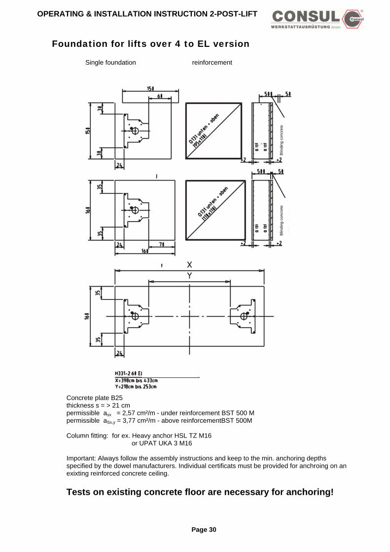
Foundation for lifts over 4 to EL version
Single foundation reinforcement
Blin
ding
con
cret
e
Blin
ding
con
cret
e
Concrete plate B25 thickness s = > 21 cm permissible asx = 2,57 cm²/m - under reinforcement BST 500 M permissible aSx,y = 3,77 cm²/m - above reinforcementBST 500M Column fitting: for ex. Heavy anchor HSL TZ M16 or UPAT UKA 3 M16 Important: Always follow the assembly instructions and keep to the min. anchoring depths specified by the dowel manufacturers. Individual certificats must be provided for anchroing on an exixting reinforced concrete ceiling. Tests on existing concrete floor are necessary for anchoring!
Page 30

OPERATING & INSTALLATION INSTRUCTION 2-POST-LIFT
Floor fixing for chain lifts H264/H265
B = thickness of floor covering grad 21 cm h = anchoring bolt depth by B25 s = thickness of floor material til concrete B25 t = foot plate thickness g = screw length L = dowel length X = according to the instructions of manufacturer dowel length: L = h + s + t + g Accordance to type anchor used for the 21 +1 hole in the base plate, the washer must be of sufficient size. Subject to change without prior notice!
Page 31

OPERATING & INSTALLATION INSTRUCTION 2-POST-LIFT
Foundation chain lifts H264/H265
Underground Permissible sigma b=200KN/m² B25, BST 500 M Concrete floor > 2,0 cm
Page 32
Permissible sigmaB > = 150 kN/m² B 25, BST 500 M Concrete floor > 2,0 cm
Concrete plate B25 thickness s = > 21 cm permissible asx = 2,57 cm²/m - under reinforcement BST 500 M permissible aSx,y = 3,77 cm²/m - above reinforcement BST 500M Column fitting: for ex. Liebig adhesive anchors Type 12 for Hilti HVA/HAS-M12x110 Important: Always follow the assembly instructions and keep to the min. anchoring depths specified by the dowel manufacturers. Individual certificats must be provided for anchoring on an exixting reinforced concrete ceiling. Tests on existing concrete floor are necessary for anchoring!

OPERATING & INSTALLATION INSTRUCTION 2-POST-LIFT
Floor fixing H342
Attention! Base frame height= 60 mm Base frame must be placed on the total surface! Base frame in a horizontal position!
frame Anchors: HSL-G-TZ M12/50 according to the instructions of manufacturer
Subject to change without prior notice !
Page 33

OPERATING & INSTALLATION INSTRUCTION 2-POST-LIFT
Installation and Commissioning H300/H301/H339/H327/H331 In order to install a lift perfectly correctly the concrete must be flat and horizontal and have the required load strength (min. B25). Firstly the lift columns must be placed in position. The distances between the base plates of the columns are to be taken from the relevant plan. In accordance with EN1493 there must be a safety margin of 500 mm minimum between the lift columns and any other obstacle (wall etc) and, similarly, between any load to raised and another obstacle. Lifts with a max. 4 to capacity: Only insert plugs for the base plates after the assembly site has been repeatedly checked. (The base plates must lie perfectly flat!). Fixing bolts M12 or M16 are to be used. Select these in accordance with the section “Foundations“. Other brands can be used, as long as they are suitable for concrete. Plugs are not supplied. Lifts with a capacity of up to 6 to : Only insert plugs for the base plates after the assembly site has been repeatedly checked (The base plates must lie perfectly flat!) Then M16 heavy anchors are to be used. Select these in accordance with the section „Foundations“. Other brands can be used, as long as they’re suitable for concrete. Plugs are not supplied. Securely screw down the base plates of the main column and the slave column. Torque for the screws to standard 8.8 = 200 Nm. The lift columns should be vertical. On no account should they lean inward. A slight outward lean (up to 10 mm ) is desirable. If necessary extra shims can be placed between the column base plates and the floor for levelling purposes. In the slave column are the cables which connect to the main column. These cables are taken under the floor to the main column by means of a hollow pipe provided on site. An overhead conduit can also be provided through which the cables can be fed. When installing the cables it is important to ensure that the wires are not mixed up! Before commencing the electrical work carefully read and observe the instructions regarding initial installation (follwing pages)! Consul Service is available should there be further questions. The electrical installation of the lift must be carried out by an electrical engineer and according to the enclosed circuit diagram and IEE regulation 0100. The lift should operate in accordance with the travel direction symbols when the main drive switch is activated. If necessary, change the direction of turn by swapping around the 2 relevant leads.
Caution: Protective conductor checks must be carried out following initial installation, after repairs, after alterations to the installation, as well as prescribed under the VDE regulation 0100!
Lifts with a capacity of up to 4 to: With the lift down pull the angled sides of the locking bars out from the lift until approximately 40 mm remain on the other side. Grease the take-up bolts thoroughly. Turn the angle of the lower locking bar upwards and fix it along with the swivell arm. Turn the elbow of the upper locking bar into the drilled hole with a pair of pliers after the swivel arm has been fitted. Lifts with a capacity of over 4 to: If necessary do a follow-up adjustment on the security stops on the swivel arm bolt. The security stops must alllow the swivel arms to swing in the lower final location but they must not stick out more than 3 to 5 mm (max.) above blocking washer segment. (see drawing) When the lift has been lubricated at the column according to the lubrication schedule and its operation has been checked (according to BGG945) by a qualified engineer, then commissioning can begin. Securing of the lift apparatus (eg, swivel armes) against being disconnected.
Page 34

OPERATING & INSTALLATION INSTRUCTION 2-POST-LIFT
Secure the eye bearing with a hexagonal safety screw on the take-up bolt so that there remains a gap of 1 to 2 mm between the eye and the screw head. Attention: The self-securing screws only reach complete turning security after 24 hours. The H300 C lift with sill lifting chassis: Attach the chassis and secure it against slipping out of the take-up bolts with M10 hexagonal safety screws. The locking device on the lifting carriage can be removed if necessary. The fixing brackets for the tension band must be sufficiently spaced from the column so that the tension band does not catch and get damaged. The fixing brackets may need some follow-up adjustment. The spindles must be oiled and the spindle oilers on the lifting carriage are to be filled with Consul Spindle Oil using the observation holes on the columns (order no: 24960.3) Should there be a buzzing noise from the tension bands when the lift is in drive then multi-purpose grease can be applied to the back of the cover. By doing a test run, check or reprogramme the end cut-out switches and the safety stop top and bottom.When the lift’s operation has been checked according to BGG945 by a qualified engineer, commissioning can begin. The results of the check must be recorded in the check book.
Page 35

OPERATING & INSTALLATION INSTRUCTION 2-POST-LIFT
Installation and Commissioning of Chain Lift H264/H265/H325 Set up the base frame (special accessory) in the desired location. Anchor it to the floor using safety plugs. Torque of the M12 safety plugs according to the instructions of the manufacturer. The anchor bolts must locate securely in the concrete according to the manufacturer’s instructions. The base frame must lie completely flat. When installing the base frame, the M16 x 45 screws inserted in the frame must be used! (The M16 x 40 screws contained in the standard accessory kit must not be used). In accordance with EN1493 there must be a safety margin of 500 mm minimum between the lift columns and any other obstacle (wall, etc) and, similarly, between any load to be raised and another obstacle. After setting up the columns bring the lifting carriage (untensioned lift) to the same height. Insert plugs for the base plates (the base plates must lie quite flat!).It is necessary to use 10 heavy duty M16 anchor bolts (eg, Hilti HSL -G -TZ, or sumilar anchors from another manufacturer). After setting up the columns bring the lifting carriages on unternsioned lifts to the same height and pull the chain up. When doing this ensure that the glide unit of the chain break switch lies cleanly on the chain and that the activating pin does not yet touch the limit switch. Only when the chain breaks can the limit switch tappet be pressed upward so that the drive is switched off. If necessary the limit switch may need readjusting (by moving it vertically). Position the chain guide approximately 1,3 m from the base plate. Then install the chain cover so that the hole in the sheet metal lies above the M6 thread of the chain guide. The base plate (with the columns) is raised until the chain is under slight tension. After repeatedly checking the installation site, insert the plugs for the base plates (the base plate must be completely flat! To bolt down the base plates, 10 M16 heavy duty anchors are necessary ( eg. Hilti HSL - G - TZ, or similar anchors from another manufacturer). The drilling depth in the concrete (BN25) must (eg, Hilti HSL G-TZ) be to a minimum depth of 125 mm. The depth of the anchor bolt must be no less than 100 mm. The plugs must have a minimum resistance strength of 9 kN. The torque value is 120 Nm. The length of the plugs to be used should be according to the information in the section “Foundations”. The above mentioned plug information relates to Hiliti Heavy Duty Anchors HSL - G - TZ M16. Other makes of plug may be used as long as they are a permitted design for the concrete. Plugs not included. The lift columns should be vertical. On no account should they lean inward. A slight outward lean (up to 10 mm ) is desirable. If necessary extra shims can be placed between the column base plates and the floor for leveling purposes. First screw the main column to its base plate ( torque 200 Nm ) then push the (lightly screwed down) slave column outwards in order to connect the chain. For this use the enclosed chain adjustment plate. Stick the narrower side through the near side of the distance plate (long hole downward) and turn it through 90 degrees. By a short pull on the plate check that it does not slip out. Finally stick a larger screwdriver (or something similar through the hole. The lower end of the screwdriver should lever itself againgst the firm base plate! Now the chain can be tensioned by pulling back the screw driver (or an assembly tool which can lever itself against the enclosed chain plate can also be used for the purpose). The chain has the correct tension when it can be pressed together in the middle (without chaing guide) using only hand power. The slave column is likewise screwed to its base plate with a torque of 200 Nm. The chain guide is screwed to the chain plate using the enclosed 12 M6 screws (with washers). If the available floor is not even and the chain cover does not lie flat (clattering noise), then the cover must be secured with 2 screws. For this drill 2 holes through the middle of the sheet metal, diameter 9 mm (each
Page 36

OPERATING & INSTALLATION INSTRUCTION 2-POST-LIFT
one 100 mm from the outer edge of the sheet metal). Lay the drilling template on the floor and let in 2
plugs (100 mm diameter). Finally screw the chain cover to the floor using 2 wood screws (8 mm diameter). There is an additional sheet enclosed for the chain cover of the H264/H265 lift with symmetrical bearing arms. If necessary, screw this in the same way as described above. When installing the electrical cables be careful not to mix up the wires! Before commencing the electrical work, the instructions for initial installation (following pages) should be read and observed! If any further questions arise, Consul service is at your disposal. The electrical installation of the lift must be carried out by an electrical engineer according to the enclosed circuit diagram and IEE Regulation 0100. The lift should operate in accordance with the travel direction symbols when the main drive switch is activated. If necessary change the direction of turn by swaping around the 2 relevant leads. Attention: If turned in the wrong direction, on no account should you continue to the end position as the lift will get stuck. Lower the carriages, pull out the short angled ends of the arm-lock so that about 40 mm remains on the other side. Grease the carriage pivot points well. Turn the angled end of the lower arm-lock upwards. Fit the lifting arms, insert the lwoer arm lock into the arm at the same time. The angled end of the upper arm-lock must be turned with the aid of pliers into the relevant holes after the swing arms have been fitted. Secure the lifting arms with the spezial bolts provided. With the lift H264-C with sill lifting chassis, the chassis is connected and secured against slipping off the take-up bolts with hexagonal M10 screws. The locking device of the lifting carriage can be removed if necessary. The buffer points are installed and secured using the enclosed springs.
Caution: Protective conductor checks must be carried out following initial installation, after repairs, after alterations to the installation, as well as prescribed under the VDE regulation 0100!
See drawing After installing the lift be careful to ensure the correct alignment of the switch wire in the main column. The switch plates must be located between the back wall of the column and the backing plate. Check the spindle cover. The fixing brackets for the tension band must be sufficiently spaced from the pillars so that the tension band does not catch and get damaged. The fixing brackets may need some folow up adjustment. If the tigehtening strap creates any summing sounds during operation, lubricate the back of the strap with some grease. Test the end cut-out switch top and bottom with a trial run. When the lift has been lubricated according to the lubrication shedule on the main column and its operation checked by a qualified engineer in accordance with BGG945, then commissioning can follow.The result of the test must be recorded in the test book!
Page 37

OPERATING & INSTALLATION INSTRUCTION 2-POST-LIFT
Chain break switch H264/H265/H325
A = spindle B =bearing holder C = chain D = cover for the limit switch E = confirm shaft F = column (column base plate) G = compression spring H = connection element I = safety ring J = woodruff key K =limit switch complete L =bearing M = chain wheel After trial runs with a nominal load, the chain break switch should be checked for trouble-free operation and readjusted if necessary!
Page 38

OPERATING & INSTALLATION INSTRUCTION 2-POST-LIFT
Installation and Commissioning H342 In order to install a lift perfectly correctly the concrete must be flat and horizontal and have the required load strength (minimum BN 25). In accordance with EN1493 there must be a safety margin of 500 mm minimum between the lift columns and any other obstacle (wall, etc) and, similarly, between any load to raised and another obstacle. Lay out the base frame in the desired location so that the main column is on the right when seen from the drive-on direction. The receiving plate for the chain break switch on the base frame will similarly be on the right. It can then be assigned to the main column. The base frame is anchored to the concrete with safety plugs or masonary screws AM16x200 DIN529-4.6 vz (rust resistant steel). Torque of masonary screws M16 75 Nm, safety plugs M12 per manufacturer’s instructions. The fixing bolts must be at least 150 mm deep into the concrete. The masonary screws and plugs are not included. The base frame must lie completely flat. Bring the foot of the slave column (without control box) right up to the fixing point on the base frame. Push the connecting cable through the cable conduit inside the column. It is important to keep some spare length so that the column can be moved when tensioning the chain. The cable is then pulled further through the cable canal in the base frame. The slave column is now set up. Secure the column with screws. The cable must not be snagged or damaged. The main column is put in place as described before. The end of the cable is pulled tight and then pulled from below throught the column base plate and the conduit inside it. The cable for the chain break switch is installed in the same conduit in advance. Set up the slave column, pull lossely secured cables and run them through the back wall of the column to the control box. Move the columns in the long holes with the smallest distance between them, bring the lifting carriage to the same height and put on the chains. Shorten the chain as appropriate and connect to the enclosed chain lock. Move the main column outwards and screw it securely to the base frame. Move the slave column out using the chain tensioning screw until the chain, removed from its guides, is sufficiently taut to allow it to be squeezed together by hand so that the chain lengths touch. Screw the slave column securely to the base frame. Torque value for the M16 screws, standard 8.8 = 200 Nm. The litf columns should be vertical. On no account should they lean inward. As slight outward leand (up to 10 mm) is desirable. If necessary extra shims (enclosed with accessories) can be placed between the column base plates and the base frame for levelling purposes. After completing the assembly of the chain break switch (the cable should be shortened as appropriate) and the chain guide, the chain as well as the switch lever require greasing (see drawing). Securing the lifting apparatus (eg, swivel arms) against accidental disconnection. Secure the eye bearing with hexagonal safety screw on the take-up bolt so that there remains a gap of 1 to 2mm between the eye bearing and the screw head.
Page 39

OPERATING & INSTALLATION INSTRUCTION 2-POST-LIFT
Attention: The self-securing screws only reach complete turning security after 24 hours.. As a first step when assembling, check that the cables which have been laid are undamaged and correctly located. The cables of the slave column and the chain break switch should show no slackness in the region of the switch box conduit or loop slackly into the columns. They should rug closely together. Establish the electrical connection. The electrical installation of the lift must be performed by an electrical expert on the basis of the connection diagram provide and of the VDE regualtion 0100. Operate the operating switch, the lift must move in accordance with the direction of travel symbols, if necessary alter the direction of rotation by interchanging two conductors.
Caution! Protective conductor checks must be carried out following initial installation, after repairs, after alterations to the installation, as well as as prescribed under the VDE regulation 0100!
Check the spindle cover. The fixing brackets for the tension band must be sufficently spaced from the columns so that the tension band does not catch and get damaged. The fixing brackets may need some follow-up adjustment. The spindle must be oiled and the spindle oilers on the lifting carriage are to be filled with Consul Spindle Oil using the obser (order no: 29460.3). Lifts with eletrooilers grease automatically the spindles of the lift. Control regularly the level of the oil that can be seen from outside and if necessary refill (see Maintenance and care and the sheet on the lift). Should there be a buzzing noise from the tension bands when the lift is in drive then multi-purpose grease can be applied th the back of the cover. Test the end cut-out switch top and bottom with a trial run. If necessary readjust the locking pins of the swivel arms. In the lower position, the locking pins can be only max. 3-5 mm over the rotary segment. When the lift has been lubricated according to the lubrication schedule on the main column and its operation checked by a qualified engineer in accordande with BGG945, then commissioning can follow. Test the chain break switch (see drawing ) is operating before fixing the base frame cover. To do this push the chain sideways with a implement (eg, shaft of hammer) until the limit switch is activated. The lift can then no longer be set in drive by moving the drive switch. If necessary install a limit switch. Depending on the model of the lift pay attention to the correct positioning of the switch wire in the main column. The switch plate must be located between the back wall of the column and the backing plate. Check the spindle cover. The fixing brackets for the tension band must be sufficiently spacedfrom the columns so that the tension band does not catch and get damaged. The fixing brackets may need some follow-up adjustment. The buffer points are installed and secured using the enclosed springs. (see drawing) The results of the check must be recorded in the check book
Page 40

OPERATING & INSTALLATION INSTRUCTION 2-POST-LIFT
Switch again chain break H342
1. twist joint 2. limit switch 3. fillister head 4. switch lever 5. Seeger-annular gear 6. compression spring 7. slider
Page 41

OPERATING & INSTALLATION INSTRUCTION 2-POST-LIFT
Safety lock device (load nut failure) Your lift is equipped with a safety lock that tops the lift operating once a load bearing nut has failed. For explanation of the function of the safety lock device, please read the following drawing. Fig. 2 and 3 show the position of the load bearing nut and respectively the safety nut with the angled safety catch between the two nuts on the driving angles. The load carrying device are enclosed within the lifting carriage and cannot be accessed from outside. When running the lift in normal operation, there is a clearance between safety nut and carriage which allows the safety nut to run unloaded. If the thread of the load bearing nut is worn, the carriage falls on the safety nut and and activates the safety lock which presses against the back wall of the column (see fig. 3). In this defected state of the supporting elements, the lift can only be lowered. If the carriage is moved upwards again, the safety lock catches on the bar on the back wall of the lift and stops the lift rising. The locking mechanism must under no circumstances be disconnected. If the lift stops about 10 mm above the ground level, the supporting elements are defect. According to the safety lock device, the lift has to be out of function before repair by trained engineers. Repairs carried out by no trained personnel may lead to serious accidents. ! To prevent on time the failure of the nut, proceed as follows:
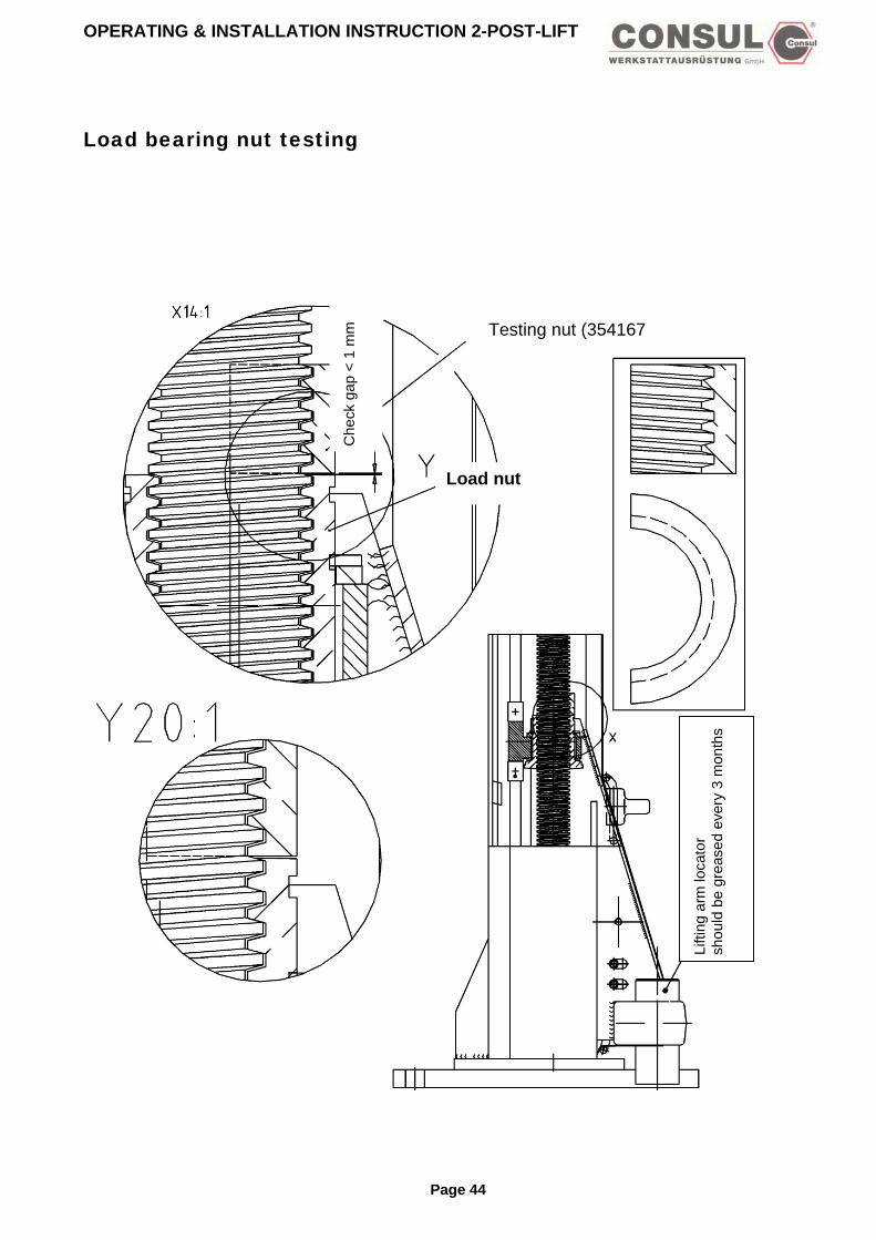
Load bearing nut testing with safety nut „trapezoidal thread Tr45x6”, available as special accessory (Ident-Nr.: 35416.7). 1. Remove the tightening strap, til safety nut in the carriage can be seen. 2. Move the lift upwards with the corresponding level and maintain. 3. Fixe the testing nut on the spindle, turn to the left til the testing nut draw up the supporting nut. 4. Lower the lift 5. Measure the slit between the supporting nut and the testing nut with a gauge or vernier. If the wear is over 1mm, the supporting nut has to be replaced !
Page 42

OPERATING & INSTALLATION INSTRUCTION 2-POST-LIFT
Load failure nut
Roller bearing
Load nut
Carriage
Bar
Safety Lock
Safey nut
Fig 2Load nut o.k.
Fig 3Load nut destroyed
Page 43
OPERATING & INSTALLATION INSTRUCTION 2-POST-LIFT
Load bearing nut testing
Che
ck g
ap <
1 m
m
Page 44
Testing nut (354167
Load nut
Lifti
ng a
rm lo
cato
r sh
ould
be
grea
sed
ever
y 3
mon
ths

OPERATING & INSTALLATION INSTRUCTION 2-POST-LIFT
Description of the main board SGMX2 for EL-lifts Overview: The lift is equipped with an electronic control board. The upper and lower limits can be adjusted to required circumstances. The stored data can be adjusted to required circumstances. The stored data is permanent and will not be lost when there is no power. During the first installation of the lift, it is necessary to check the adjustment of the upper and lower limits. If necessary, they have to be adjusted. Required adjustments during installation: Adjustment of lower and upper limits. Synchronisation of both carriages. Adjustment of the safety Stop when lowering at a height of min. 200 mm above the ground. Safety stop: When lowering the lift, the carriages stop at the programmed point. After pushing the down button agains, the carriages continue to the lower limit. You can hear the auditible warning noise during this operation. Attention! During programming the lift, the automatic limits do not work. –danger of collision in the upper and lower limits-. Take care of approx. 10 mm overrun. Initial installation: Due to different local requirements and individual wishes, the different limits must be programmed. Standard adjustments: The lower limit: Between the lowest point of the arm and the ground, there should be at least 10 mm of space. The upper limit: Between the base plate and the lowest point of ther arm, there should be
A max. difference of 1900 mm. Safety stop: There should be a minimum of 200 mm between the lowest point of the arm and the
ground. Preparation for the initial installation: During the initial installation of the arms, or after repair, these should be conducted approx. 10 mm over the lowest position as in the normal case. The lower position drive can be carefully followed with the lever up/down in twice or indiviudal drive. Notice: The potentiometers are protected against mechanical breakage by means of a mechanical
end stop. It is possible, that the lower limit cannot be reached by using the motor. In this case, the potentiometer has to be dismounted and the carriage should be lwoered by turning the pulley on top of the lift. When reaching the lower limit of the carriage, turn the potentiometer clockwise until you reach the mechanical end stop. After that turn it back half a turn.
In the lower lifting carriage position the path transitter pinion when unlocked is turned clockwise (seen from above) until it reaches the mechanical Stopp, then turned back half a turn. With light pressure it will then return to the locked position and the M6 safety screw of the path transmitter mounting is again secured. Make sure there is an undamaged spring wahser under the screw head.
Page 45

OPERATING & INSTALLATION INSTRUCTION 2-POST-LIFT
Switches on the main board for EL lifts
Switch on the electronic-platine for initial installations and programmation
SGMX 2
LED Motor 2
LED Motor 1
Setting
CodiSchaEnter
Tasteer-lter
Enter-button
Code switch(rotate with a small screwdriver)
Code switch Enter
button
Not plugged
Gre
en
Whi
te n n n
Switch position: 0 1 2 3 4 5 6 7* 8* 9* *If you encounter any fault during these test modnormal mode in this case. If normal drive mode ovecame this situation, change defective parts o Programming (Initial installation of the
Step: Switch position:
Enter button:
A 4 push
B 5 push C 1 push
push D 2 push
push E 0 push
F 3 push push
G 0 push
H 6 push push
I 0 push
push = both LED are green push = both LED are blinking green
Brow
Gre
eW
hite
brow
Function: Normal drive mode Lower limit of carriage Syncrhonisation of carriages Upper limit of carriage Operate mode master column only Operate mode slave column only Security stop and acoustic signal Potentiometer test mode Connection, signal and EEPROM test mode Fault test mode (spezial test from manufacturer)
es, this fault will be stored on the EEPROM . The main board cannot be adjusted to is selected, and a fault occurs during test mode, both red and green LED’s blink. To r run test mode again.
potentiometer already done)
Function:
operate mode master column only lower the carriage til approx. 10 mm over the ground and 10 mm overrun reserve operate mode slave column only (as step A) set lower limit after success of step A and B save mode synchronisation of carriages save mode normal operation mode (both LED are red) move both carriages til a height of max.. 1900 mm - evt. lower. set upper limit after success of step E. save mode normal operation mode (both LED are red) lower lift to a min. 200 mm above ground in order to set safety stop set safety stop after success of step G save mode normal operation mode (both LED are red) programming finished. Should be the above disconnecting point not reached,
continue in individual drive with position 4 and 5 Attention: no end stops !
Page 46

OPERATING & INSTALLATION INSTRUCTION 2-POST-LIFT
Important notice: If you encounter big differences in voltage or any other problems, it might happen that the main board is shut down automatically for safety purpose. In this case the lift cannot be operated. To make it work again, this can be done usually by turning the main switch on and off again.
The path pick-ups P1 and Pwiring of the path pick-ups the path pick-ups! When fitting a newthe control sequenwill help! How to active the EEP 1. Main switch off 2. Jumper on both plugs 3. Main switch on 4. Jumper on one plug or p5. Main switch off 6. Main switch on 7. The control is actived by Test connections, sig(Carriages are not nea 1. Turn switch to code 8. 2. Push ENTER button 3. LED 2 is blinking (green4. Turn the „up“ switch unti5. The lift will move a short6. LED 1 is blinking (green7. Turn the „down“ switch u8. The lift will move a short9. If the test has been succ10. If any fault accured, both11. Push ENTER button (EE12. If everything is ok, both L13. If the electronic encount
turned off. The jumper oagain, put the jumper on
14. Set code switch to any m15. Push ENTER
Lifting screw with threat
wh
p r
2 armus
Ece
RO
ut it
turn
nalr th
), thl the dist), thntil distess LEPRED
ers hn thto oode
otentiomete
white brown green
ite brown green
e not marked on the lift. The configuration of the components corresponds to this drawing. The t be carried out according to the colour scheme of the prescribed plan. Incorrect wiring upsets
EPROM or circuit board or in the event of any interruption to which cannot be dealt with, carrying out the following steps
M
away until end of this process
ing the code switch to 8 and pushing the Enter button
and EEPROM (Saving) e end stops)
e signal is on. carriages start to move up. ance upwards. e signal is on. the carriages start to move down. ance downwards. full, both LED are blinking green. D are blinking red. OM-Test) are green. ave any problems, both LED are blinking red, the signal is on. To rectify the fault, the lift has to be
e main board has to be put onto both connections, turn main switch on. After that turn off main switch ne connection only and turn main switch on again. .
Page 47

OPERATING & INSTALLATION INSTRUCTION 2-POST-LIFT
Switches on the main board for 1 motor-lifts Switch on the electronic platine for initial installations and programmation
SGMX 2
LED Motor 2
LED Motor 1
Brücken genicht
steckerbrückt
EnterTaste
CodieSchalt
r-er
Enter-button
Code switch(turn with a small screwdriver)Not
plugged
Code switch Enter
button Gre
en
Whi
te n n
Switch position: 0 1
3 4 5
6 7* 8* 9* *If you encounter any fault during these testnormal mode in this case. If normal drive movercame this situation, change defective pNew driving mode: Switch on the main board – prog
Step Switch Enter button:A 4 push
B 5 C 1 push
push D 2
E 0 push
F 3 push push
G 0 push
H 6 push push
I 0 push
push = both LED are green. push = both LEDare blinking green
Brow
Gre
eW
hite
brow
n
Function Normal drive mode Lower limit of carriage (not active) Upper limit of carriage carriage position drive (not active) Safety Stopp and acoustic signal for further lowering of carriage Potentiometer test mode Connection, signal and EEPROM test mode Fault test mode (not active)
modes, this fault will be stored on the EEPROM. The main board cannot be adjusted to ode is selected, and a fault acccurs during test mode, both red and green LED’s blink. To arts or run test mode again.
ramming (initial installation of the potentiometer already done)
Fonction: Oparate mode Lower the carriage til approx. 10mm over the ground and 10 mm overrun reserve Not active Set lower limit after success of step A Save mode Not active Save mode Normal operation mode (both LED are red) Move both carriages til a height of max. 1900 mm - evt. lower Set upper limit after success of step E. Save mode Normal operation mode (both LED are red) Lower lift to min. 200 mm above the ground in order to set safety stop. Set safety Stopp after success of step G Save mode Normal operation mode (both LED are red) Programming finished
should be the above disconnection point not reached, . Continue in individual drive with position 4. Attention: no end stops!
Page 48

OPERATING & INSTALLATION INSTRUCTION 2-POST-LIFT
Important notice: If you encounter big differences in voltage or any other problems, it might happen that the main board is shut down automatically for safety purpose. In this case the lift cannot be operated. To make it work again, this can be done usually by turning the main switch on and off again.
Top view main column: A: main column C: gear screw D: Potentiometer E: geen F: brown G: white
The path pick-ups P1 and P2 are not marked on the lift. The configuration of the components corresponds to this drawing. The wiring of the path pick-ups must be carried out according to the colour scheme of the prescribed plan. Incorrect wiring upsets the path pick-ups!How to active the EEPROM I. Main switch off II. Jumper on both plugs III. Main switch on IV. Jumper on one plug or put it away until end of this process V. Main switch off VI. Main switch on VII. The control is actived by turning the code switch to 8 and pushing the Enter button Test connections, signal and EEPROM (Saving) (Carriages are not near the end stops) I. Turn switch to code 8. II. Push ENTER button III. LED 2 is blinking (green), the signal is on. IV. Turn the „up“ switch until the carriages start to move up. V. The lift will move a short distance upwards. VI. LED 1 is blinking (green), the signal is on. VII. Turn the „down“ switch until the carriages start to move down. VIII. The lift will move a short distance downwards. IX. If the test has been successfull, both LED are blinking green. X. If any fault accured, both LED are blinking red. XI. Push ENTER button (EEPROM-Test) XII. If everything is ok, both LED are green. XIII. If the electronic encounters have any problems, both LED are blinking red, the signal is on. To rectify the fault, the lift has to be
turned off. The jumper on the main board has to be put onto both connections, turn main switch on. After that turn off main switch again, put the jumper onto one connection only and turn main switch on again.
XIV. Set code switch to any mode. XV. Push ENTER
Page 49

OPERATING & INSTALLATION INSTRUCTION 2-POST-LIFT
Faults and causes If there are any faults with the lift, turn off immediately, make safe, secure against unauthorised use and contact the Consul Service Section. Repairs are only to be undertaken by qualified engineers! - Noises during operation: Cause: Lack of lubrication, worn lifting screw, loose v-belt Remedy: Lubrication of spindles.If spindle is defective, replace it. Tighten v-Belt (replace it). - lift does not operate. Remedy: check supply current as well the fonction of the motor. Check main switch, control circuits, fine-wire fuse and thermal cut-out in motor winding and motor operation. - Lift does not raise required load, or the motor „drone“ Check that the permitted lifting capacity of the lift has not been exceeded. Check the lubrication between the load nuts and the spindle. Check the electric leads to the electric motor to see whether current is being supplied in all 3 phases. Check the safety contacts and the drive belts. - Carriage only rises approx. 100 mm. Remedy: Check safety devices, load bearing nut is probably worn and the safety lock is actived shut down the lift, secure against unauthorised use and inform Consul Service Section - Arm-lock does not work. Remedy: Check locking blocks, check springs between blocks and side of carriage, check lock bars for perfect fit or no damage Check that the permitted lifting capacity of the lift has not been exceeded. Check the lubrication between the load nuts and the spindle. Check the electric leads to the electric motor to see whether current is being supplied in all 3 phases. Check the safety contacts and the drive belts Your Consul Service Section should be contacted in the event of any other faults. Repairs of Consul lifts are only to be undertaken by authorised dealers. Only original parts are to be used. If non-orignial parts are used all warranties and liabilities are invalid.
Page 50

OPERATING & INSTALLATION INSTRUCTION 2-POST-LIFT
Emergency lowering II Important: While in the emergency lowering procedure. The automatic end limits are switched off. It is possible to drive the lift into the floor causing damage. Notes: The procedure described below for the emergency lowering of the lift may only be undertaken by authorised, trained personnel. A second person should watch the procedure from outside the operating area to ensure the safety of the operator and vehicle. The emergency lowering procedure must be terminated immediately, if any danger should arise. Restarting the emergency lowering procedure should begin again once the cause of the danger has been removed. It is only possible to lower the lift once, making sure that the bad carrying parts do not touch the floor. Operating the emergency lowering procedure: Emergency lowering using the motors can be necessary if the electronic controls fail. If other elements fail, then the lift should be lowered manually (by turning the bolt on the large pulley). The main switch must be on the „off“ position. The screws should be inserted into the two contactors and locked into position (as shown in the diagram) to enable emergency lowering. If the two sides are not synchronised then by locking only one contactor, the arms can be brought on the same level. Extreme care must be taken and levelling should be done in small steps. Locking the contactors (the second contactor is the Mirror image): Direction for pushing the operating bar
plastic screw Insert the locking screw at an angle as shown in the sketch. Using the screw, press the locking bar slighly in the direction of the arrow, then turn the srew clockwise, locks the locking bar. Set the main switch to 1. The emergency lowering procedure can be carried out by loosely inserting the switch toggle after removing it from the lid. Warning: No automatic end switching-off. When the maximum necessary lower position of the load carrying equipment has ben reached, immediately set the main switch to 0 and remove the locking immediately. Moving the unit upwards again with the locking screw in position is not permitted. The lift must not be used again until all defects have been repaired by authorised personnel.
Page 51

OPERATING & INSTALLATION INSTRUCTION 2-POST-LIFT
Emergency lowering I Important: During movements in emergency operation, there are not automatic end switch-offs. Further movements as far as the mechanical end stops may result in damage. Notes: The emergency lowering process described below must only be carried out by authorised and trained personnel. A second person must stand outside the danger area to monitor the safety of staff and materals in the lifting platforma area. At the first indication of any danger, the movement must be stopped immediately. No further movement must take place until the source of the danger has been removed. The only permitted function is a single downward movement –however, ensure that the load support equipment does not touch the floor. Emergency lowering If the eectronic control system fails, it may be necessary to carry out emergency lowering using to motor. If other elemeents fail, carry out emergency lowering by hand (by turning the big belt disc). The main switch must be set to 0. As per the sketch, the lowering contactors must be locked for a single emergency lowering process by using the enclosed plastic screws. If there is any uneveness in the lifting apparatus it may be possible to overcome this by locking just one of the safety devices, Be especially careful while carrying out all movements, which should only take place for short intervals. Locking main contactor K2 and K4: Insert locking screw in accordance with the sketch. The screw pushes the locking bar in the direction of the arrow and locks it. Set the main switch briefly to 1 in order to control the correst direction of movement of the carriage, then press the main switch again to continue the downwards movement. Warning: No automatic resetting of the main switch, no automatic end switching-off. When the maximum necessary lower position of the load carrying equipment has been reached, immediately set the main switch to 0 and remove the locking screw immediately . Moving the unit upwards again with the locking screw in position is not permitted. The platform must not be used again until all defects have been repaired by authorised personnel.
Page 52

OPERATING & INSTALLATION INSTRUCTION 2-POST-LIFT
Maintenance general care Before any maintenance the lift should be isolated from the electricity supply and protected from any unauthorised use! Thorough maintenance is essential if your lift is to have a long working lift and be constantly ready to give good service. In this respect special attention must be given to lubrication. The lifting spindles must be greased weekly with Consul Spindle Oil. When the spindle is in the „down” position, brush the lifting spindle with oil. Where lifts have spindle oilers (identification number: 34631.2) then the oil container on the carriage must be kept full. At least once a month you should check that the oil provision is sufficient. After installation and commissioning there may be some stretching of the power transmission elements, depending on the type of lift. For example, stretching of the drive belt, chainds or calbes, consequential adjustments, adjustments to the safety systems, etc. These changes do not constitue wear and tear of the parts. They are routine aspects of running in and must form part of the customer’s maintenace and care. With lack of care break downs can occur which are not occur which are not covered by the guarantee. In this case, any costs airsing may have to be borne by the customer. The swivel arm joints must be greased when necessary and at least quarter yearly (oil underneath the safety screws). Where lifts are exposed to the weather, the lubrication programm should be doubled (see the lubrication instructions on the main column). The load bearing apparatus must always be kept in working condition. The buffer points must be kept clean and greased-free. The spindles of the turntables must must be greased. They must not be able to unscrew themselves completely. Chain lifts: One further point is the correct tensioning of the chains. Because of the initial stretching of the chain it is necessary to retension these as required. Thi is not a sign of early wear. After a short running in time the chain generally requires retensioning. The retensioning of the chain (only with tension lifts! ) is an item of maintenance which must be carried out by the customer as and when necessary. Damages which occurs when the lift is operated with an overslack chain will invalidate the guarantee. The tensioning of the chain is to be carried out according to the instructions for assembly. The chain glide units should be stored clean and in well-greased conditions (to be checked quarter yearly).
Page 53

OPERATING & INSTALLATION INSTRUCTION 2-POST-LIFT
Automatic lubrication system 1. 2.
3.
4.
5.
Checovvisibmai
Remove the cove plate at the rear of the column.
Raise the lift to the ipper column opening so that the carriage stopfs between the upper roller and the angle piece. Important! Before carrying out any work at all on the lift, always disconnect it from the mains electricity supply and ensure that no unauhjorised personnel can use it. Fill the oil container with oil(we recommend lubrication SAE 20). The flat wick should be secured about 20-25 mm over the oil container with a safety needle and fitted pointing downwards. Please check during assembly!
Clamp the oil container to the carriage. Repeat this procedure on the column. Then check the correct position of the oil container again!
Now replace the cover plates and connect the lift to the mains agains.
ck the oil at regular intervals. To do this, remove the er plate and raise the carriage so that the oil container is le through the opening. Disconnect the lift from the
ns supply. Check the oil level and top up with oil if
O
Page
Plasticcover
il tank
carriage
54

OPERATING & INSTALLATION INSTRUCTION 2-POST-LIFT
Adjustment for synchronisation 34987.8 (3to) 38096.4 3,5 and 4to
Slider
spring
Nutandbolt
If necessary, adjust the pre-tensionof the spring by means of the nut!
-+
The lift has an adjustable brake on both columns. This stops the weightof the vehicle causing the columns to lower at differentspeeds. The tension on the springs can be adjusted to synchronisethe lifting carriages.
Subject to change without prior notice!
When the hood has been removed and the system is load-free, it should just be possible – using both hands – to turn the large belt disc.
Page 55

OPERATING & INSTALLATION INSTRUCTION 2-POST-LIFT
Manual arm lock override
Manual arm lock override Accessories Order-no. 34990.2
Manual of arm lock override Remove cover tape, so that you can see the spindle Put the lever through the front of the hole of the carriage Please check the lever. The U-profile have to set down on the first threat bar. Screw the lever on the guide bar (2x) Screw the guide bar in the threated bore of the lever (7 mm deep). (2x) Screw the arm lock override of its function Fasten the cover tape with the metal stripe and the nuts again. Subject to change without prior notice!
Page 56

OPERATING & INSTALLATION INSTRUCTION 2-POST-LIFT
Manual arm lock override for 6 to lifts Identification nr.: 39766.1
6855.1ball handle
667.6threaded stud
37374.6plunger block
Subject to change without prior notice!
Page 57
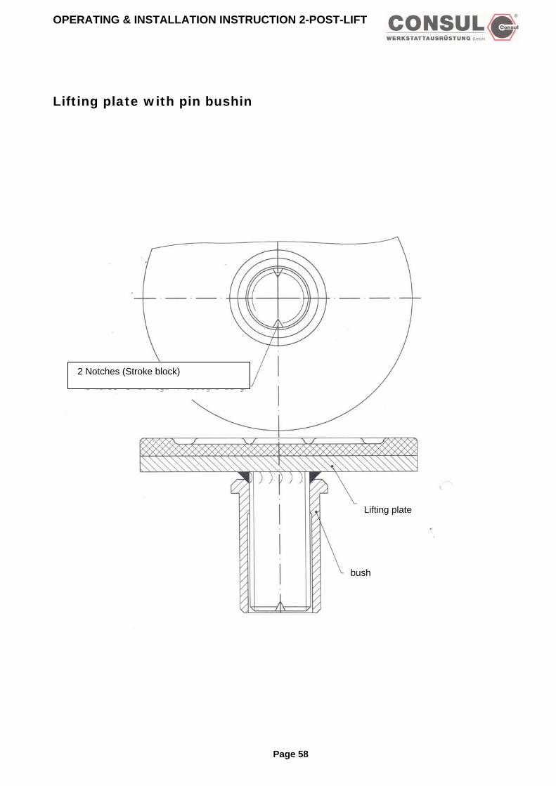
OPERATING & INSTALLATION INSTRUCTION 2-POST-LIFT
Lifting plate with pin bushin
2 Notches (Stroke block)
Lifting plate
bush
Page 58

OPERATING & INSTALLATION INSTRUCTION 2-POST-LIFT
Lifting plate lift 6 to
Pull outwards and lift into position
269407 safety spring
Page 59

OPERATING & INSTALLATION INSTRUCTION 2-POST-LIFT
Control unit with rotary reversing switch (36953.8) (for H300/H301/H354/H355)
Page 60

OPERATING & INSTALLATION INSTRUCTION 2-POST-LIFT
Control unit with rotary reversing button (36953.8) ab Fabrikations-Nr./from serial number: 209602 Pos. Ident-Nr.: description: 1 366553 operating switch 2 369546 main switch 3 361576 audible alarm device 4 356154 circuit board 9 370528 conduction band with plug 11 370536 box complete 13 369561 handle knob with adapter 19 318964 main contactor 23 316026 european socket 28 360115 fuse socket 29 318972 fuse 30 318980 fuse 11/2000 Subject to change without prior notice !
Page 61

OPERATING & INSTALLATION INSTRUCTION 2-POST-LIFT
Control unit with push-buttons 38032.9
Subject to change without prior notice !
Page 62

OPERATING & INSTALLATION INSTRUCTION 2-POST-LIFT
Control unit with push-buttons 380329 Pos. Ident-Nr.: description: A 380337 double switch B 361576 audible alarm device C 356154 circuit board D 370528 conduction band with plug E 395970 box complete F 318964 main contactor G 316026 european socket H 360115 fuse socket I 318972 fuse J 318980 fuse K 369546 main switch 10/2002 Subject to change without prior notice !
Page 63

OPERATING & INSTALLATION INSTRUCTION 2-POST-LIFT
OPERATING & INSTALLATION INSTRUCTION 2-POST-LIFT
Page 64
Control unit H325 Prolift 3003 GA
Page 64

OPERATING & INSTALLATION INSTRUCTION 2-POST-LIFT
Spare parts list control unit H325 Prolift 3003 GA Pos. Ident-Nr.: description: 1 366553 operating switch 3 361576 audible alarm device 4 356154 circuit board 9 370528 conduction band with plug 11 370536 box complete 13 369561 handle knob with adapter 19 318964 main contactor 28 360115 fuse socket 29 318972 fuse 03/2002 Subject to change without prior notice !
Page 65

OPERATING & INSTALLATION INSTRUCTION 2-POST-LIFT
Electric diagram for chain lifts H264/H265
Page 66

OPERATING & INSTALLATION INSTRUCTION 2-POST-LIFT
Electric diagram H342
Page 67

OPERATING & INSTALLATION INSTRUCTION 2-POST-LIFT
Electric diagram H325
Page 68

OPERATING & INSTALLATION INSTRUCTION 2-POST-LIFT
Electric diagram with rotary reversing switch
Page 69

OPERATING & INSTALLATION INSTRUCTION 2-POST-LIFT
Electric diagram with push-button
Page 70
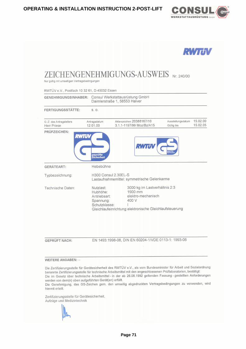
OPERATING & INSTALLATION INSTRUCTION 2-POST-LIFT
Page 71

OPERATING & INSTALLATION INSTRUCTION 2-POST-LIFT
Page 72

OPERATING & INSTALLATION INSTRUCTION 2-POST-LIFT
Page 73

OPERATING & INSTALLATION INSTRUCTION 2-POST-LIFT
Page 74

OPERATING & INSTALLATION INSTRUCTION 2-POST-LIFT
Page 75
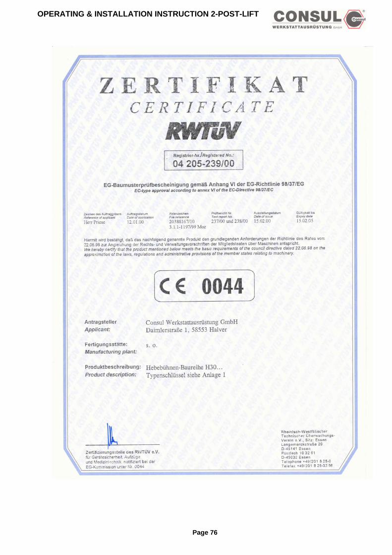
OPERATING & INSTALLATION INSTRUCTION 2-POST-LIFT
Page 76

OPERATING & INSTALLATION INSTRUCTION 2-POST-LIFT
Page 77

OPERATING & INSTALLATION INSTRUCTION 2-POST-LIFT
Page 78

OPERATING & INSTALLATION INSTRUCTION 2-POST-LIFT
Page 79

OPERATING & INSTALLATION INSTRUCTION 2-POST-LIFT
Page 80