Embed Size (px)
Citation preview

RECENT IMPROVEMENTS IN PRIMARYREFORMER FURNACES
The primary reformer furnace is undergoing a continuing appraisal ofrefinements as influenced by service experience and based on advancesin materials and design technology.
J. L. Jacobowitz & L. A. Zeis
M. W. Kellogg Co.New York, N.Y.
As part of the recent increase in world ammonia pro-duction, the processing plants developed and installed by theM. W. Kellogg Co. have played a significant part. An essen-tial contributing factor to this operation has been the success-ful development of an improved, high pressure reforming fur-nace. Considering the high pressure and high temperatureconditions, various special materials and fresh approaches tomechanical design have been incorporated. The primary re-former furnace should be- operated and monitored within closelimits because it contains hydrogen rich gas under high pres-sure and temperature. Operating experience has included iso-lated incidents responsible for damage to the furnace and forlost production time but no injuries to personnel.
Careful design attention has been applied to safety consid-erations, including materials, fabrication and constructionalprocedures. This article outlines several of the more importantconcepts and details to which special attention has beendirected and subsequent refinements made to the basic design.
There are no accepted safety Codes which are directly ap-plicable to furnace coils, principally because the high metaltemperatures involved are beyond the applicable Code range.Materials are, of course, specified and processed in accordancewith the principles of recognized standards such as ASTMand AGI, and various components are designed and fabricatedin accordance with the principles of API recommended prac-tices, the ASA Piping Code, ASME Code for Pressure Vesselsand the AISC Structural Code. To supplement these guides,we have prepared detailed design requirements consistent withthese code principles. Materials and fabrication are suppliedaccording to standards and methods developed with experi-enced and reputable vendors.
Arrangement and Operation
Figure 1 shows an overall view of a typical reformer furnace.Figure 2 shows a schematic reformer furnace layout.The process stream from the furnace convection section is
distributed to each row of radiant section tubes by a wroughtcarbon steel inlet manifold. The inlet manifold is supportedfrom the arch steel and anchored at the center, with expan-sion guides at the ends. Each radiant tube is connected to theinlet manifold thru a carbon or low alloy steel pipe pigtail ofsmall diameter bent to serpentine configuration which accom-modates thermal deflection. The tubes are supported in pairsfrom the arch steel by springs.
The process stream flows downward thru the centrifugallycast 25 Cr—20 Ni (HK40) catalyst containing tubes and is col-lected in a wrought Incoloy 800 outlet manifold located at thebottom of and within the furnace. An HK40 outlet riser tube
r-'tt
Figure 1. Primary reformer furnace
at the center of each outlet manifold then conducts the streamto the effluent chamber vessel (sometimes referred to as thetransfer line) also supported above the furnace by springs. Theprocess stream passes from the effluent chamber to the second-ary reformer vessel. Note that the direction of firing is parallelto the vertical tubes, does not impinge on tubes or walls, andprovides maximum heat input at the cooler end of the tubes,thereby minimizing metal temperatures.
Mechanical Design
As may be seen from reference to Figure 2, the furnace coilis an integrated design which • accommodates various me-chanical effects expected primarily from differential expansionand support considerations. During start-up operations, thesecondary reformer expands upward, carrying with it the endof the effluent chamber. The harp system (which includescatalyst tubes, riser, outlet manifold, and effluent chamber)

Figure 2. Schematic reformer furnace layout.
also expands but, because of higher temperature, and alloymaterials, to a greater extent than the secondary reformer.The support system allows differential expansion between indi-vidual tubes in the event of local catalyst deterioration andconsequent overheating. The spring support of the harp per-mits deflections in both vertical and horizontal planes. Thepermissible stress range for expansion stress given by ASA rulesis based on the ability of ductile materials to withstand ther-mal cyclic operation. Our design uses criteria based on suc-cessful operating experience to establish the design of pressurecomponents which are not ductile over part of the range. Fordesign conditions, typical thermal bending stress in cast ma-terial is 4,000 lb./sq. in. The harp system is designed to beweight load balanced and free floating, with clearances to ac-commodate movement from thermal expansion.
The controlled movement of coil components under the fore-going conditions of high pressure and differential tempera-ture expansion requires special attention to many areas. Theprincipal ones are outlined below.
Tubes and Allowable Stress
Tubes and risers are centrifugally cast 25 Chrome—20 Nickel (HK40). This cast material is excellent for resis-tance to creep and rupture at elevated temperature, but, as iscommon to all high temperature strength cast furnace mate-rials, elevated temperature strength is accompanied by lowambient temperature ductility after aging. More highly al-loyed materials are sometimes used for high pressures andtemperatures, but their ductility in all conditions is less thanthat of HK40. The low as-cast ductility of high carbon casttubes becomes even lower after aging at service temperaturesbecause of carbide precipitation. There are no known materialswhich will both have high temperature strength equivalent toHK40 and maintain ductility after exposure 'to reformer fur-nace temperatures. To accommodate this low ductility, the sys-tem is designed to minimize stresses at low and ambient temper-atures. Tension, compression and bending are reduced to very
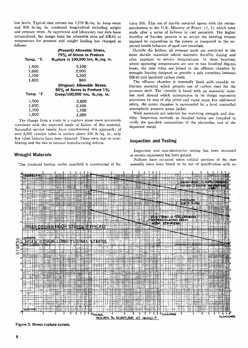
low levels. Typical, riser stresses are 1,570 Ib./sq. in. hoop stressand 928 Ib./sq. in. combined longitudinal including weightand pressure stress. As experience and laboratory test data haveaccumulated, the design basis for allowable stres sof HK40 attemperature for pressure and weight loading has changed asfollows :
(Present) Allowable Stress,75% of-Stress to Produce
Temp. °F. Rupture in 100,000 hrs, Ib./sq. in.
1,500 3,1001,600 2,0001,700 1,3001,800 840
(Original) Allowable Stress,50% of Stress to Produce 1%
Temp. °F Creep/100,000 hrs, Ib./sq. in.
1,500 2,6001,600 2,1001,700 1,7001,800 1,350
The change from a creep to a rupture stress more accuratelycorrelates with the expected mode of failure of this material.Successful service results have corroborated this approach; ofover 6,000 catalyst tubes in service above 450 Ib./sq. in., onlyfive tubes failures have been reported. Three were due to over-heating and the two to unusual manufacturing defects.
Wrought Materials
The insulated bottom outlet manifold is constructed of In-
coloy 800. This use of ductile material agrees with the recom-mendations to the U.K. Ministry of Power, (1, 2) which weremade after a series of failures in cast materials. The higherductility of Incoloy permits it to accept the bending stressesimposed by expansions in the system as compared to the ex-pected brittle behavior of aged cast materials.
Outside the firebox, all pressure parts are restricted to themore ductile materials which maintain ductility during andafter exposure to service temperatures. In these locations,where operating temperatures are one to two hundred degreeslower, the riser tubes are joined to the effluent chamber bywrought Incoloy designed to provide a safe transition betweenHK40 and insulated carbon steels.
The effluent chamber is internally lined with castable re-fractory material which permits use of carbon steel for thepressure shell. The castable is faced with an austenitic stain-less steel shroud which incorporates in its design expansionprovisions by way of slip joints and vapor stops. For additionalsafety, the entire chamber is surrounded by a level controlledatmospheric pressure water jacket.
Weld materials are selected for matching strength and duc-tility. Inspection methods as detailed below are intended toverify the specified composition of the electrodes, and of thedeposited metal.
Inspection and Testing
Inspection and non-destructive testing has been increasedas service experience has been gained.
Failures have occurred when critical portions of the riserassembly have been found to be out of specification with re-
IO,OOOH«B
Figure 3. Stress rupture curves.
gard to chemical composition. Where this condition occurs, itresults in the lowering of expected mechanical properties andpossible failure of components. Low carbon 25-20 weld metaland high chromium content castings have contributed toshorter than expected life. As Figure 3 shows, the expectedstrength of low carbon weld metal is well below that of thespecified carbon range material and so low that failure cantake place in a short time under design conditions. The highchromium content can lead to sigma formation. These off spe-cification incidents have occurred in spite of what is normallyconsidered searching inspection by reputable vendors. Present-ly, it is required that additional independent check analysisof all components in the riser system be made to assure thatthe proper analysis is present. Drillings are taken from eachheat of HK40 in the riser and from the welds joining the risercomponents. These drillings are analyzed by an independentlaboratory for % Cr, % Ni and % Carbon.
Referring to the 1967 AIChE meeting, Messrs. Avery andValentine (3) presented results of their work on expected ele-vated temperature properties of Incoloy. They showed thatthe elevated temperature strength is dependent on proper heattreatment. We have developed stringent standards for tempera-ture measurement during heat treatment to assure a true solu-tion annealed condition in all Incoloy parts not heat treatedby the producing mill. A metallographic examination is madeas a further check on proper heat treatment, although Averyand Valentine indicated that there is not a direct correlationbetween grain size and properties.
Continuing studies of relative coefficient of thermal expan-sion in materials, both in furnaces and by materials suppliers'laboratories, show generally good agreement. As more expe-rience is gained, further refinements in design will be make.These values, used throughout the industry, are directly re-lated to thermal stresses in the tubes.
Similar studies of the strength of welds in HK40 materialsare in progress. This is being supplemented by analyses of rela-tive stresses and creep deformations at the base metal to weldmetal interfaces.
Mechanical Details
The importance of free but controlled movements in the sys-tem and the minimizing of stresses due to temperature differ-ential was mentioned above. Of prime importance are thesefactors :
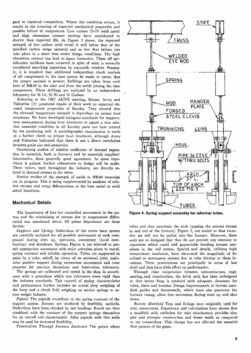
Supports and Springs Deflections of the entire harp systemare carefully analyzed for all possible movements of each com-ponent during start up, operation, emergency (local over-heating) and shutdown. Springs, Figure 4, are selected to per-mit appropriate movement with strict attention given to travel,spring constant and reliable operation. Tubes are supported inpairs by a yoke, whicrï, by virtue of its universal joint, main-tains positive support during extraneous movements and com-pensates for erection deviations and fabrication tolerances.
The springs are calibrated and tested in the shop in accord-ance with a procedure which sets tolerances more rigid thanthe industry standards. This control of spring characteristicsand performance further includes an actual shop weighing ofthe harp and a check field weighing on service springs to as-sure weight balance.
Pigtails The pigtails contribute to the spring constant of thesupport system. Stresses are analyzed by flexibility methods.Deflections have been checked by test loadings. Result are thencombined with the constant of the support springs themselvesfor an overall coil characteristic. Alloy pigtails with thin wallsmay be used for increased flexibility.
Penetrations Through Furnace Enclosure The points where
STIFF
TRUSS
WELDEDEYE ROD
SPRING
ROD
FORGEDHANGERPLATE
STEEL CLEVIS
TT R U N N I O N S
PIPE SLEEVEW/THRU BOLTS
STL.TOP OF ARCHi SEE FIG. 5
Figure 4. Spring support assembly for reformer tubes.
tubes and riser penetrate the arch (passing the process streamin and out of the furnace) Figure 5, are sealed so that exces-sive air will not be pulled into the furnace. However, theseseals are so designed that they do not provide any restraint toexpansion which could add appreciable bending stresses any-where in the coil system. Special seal details, utilizing hightemperature insulation, have decreased the magnitude of lo-calized or extraneous stresses due to tube friction at these lo-cations. These penetrations are principally in areas of lowdraft and thus have little effect on performance.
Through close cooperation between subcontractors, engi-neering, and construction, the brick arch has been redesignedso that better fitup is attained with adequate clearance fortubes, risers and burners. Design improvements to bottom man-ifold guides and thermowells, which must also penetrate thefurnace casing, allow free movement during start up and shutdown.
Bottom Manifold Tees and fittings were originally used fortube connections. Experience and calculations have shown thata manifold with weldolets for tube attachments provides sim-pler and stronger construction and fewer welds as comparedto tee connections. This change has not affected the essentialflow pattern of the gases.

OVERSIZEINSUL. \
WIRE BAND
INSULATING FIREBRICK" SLIDING
COLLAR
M IN. WOOLCEMENT "
S
TRSUL/vrioN
COVER PL.^,
TOP OF ARCH
REFflAÇ_]IiRYÎ^BfUCK l _
TUBE SUIDEPLATE\
ARCH STEEL
\CARBON_STEELOR LOW ALLOY
/REFORMER TUBE(HiC-40)
Figure 5. Reformer tube penetration details.
To protect the Incoloy manifold from overheating, long lifeinsulation on the outside of the pipe has been installed, Figure6. This has been recently redesigned as preformed halves forease of installation and positive positioning to the manifoldcontour.
Eminent Chamber Several modifications have been made inthe effluent chamber as experience has shown the way towardcontinued improvements, Figure 7.
At thermowell openings at the top, the water jacket has oc-casionally overflowed with water spilling down risers and caus-ing thermal stresses. Thermowells have now been relocatedand dams installed around any required openings.
The insulating castable lining material has been changed.The present material can be handled and installed more easilyand minimizes voids. The fabricator radiographs the installedcastable as a quality control on the extent of voids.
Riser Insulation Furnace performance has indicated thatthe top of the riser within the furnace can-be insulated with-out seriously affecting overall efficiency. The benefits from thisinsulation and retainer are threefold, Figure 8. First, the lowermetal temperature provides a higher allowable stress in whathad been the highest metal temperature area, and, for exist^ing furnaces, results in lower metal temperature for the weldsin that area. Second, there is provided a measure of protectionagainst arch damage due to escaping process gases in the eventof a riser failure just below the arch. Third, in the event ofwater spillage at the top of the furnace, the insulation protectsthe riser weld at the arch against possible corrosion andquench cracking.
Location of Riser Field Weld Current designs call for theriser field weld to be in carbon steel material above the archrather than in HK40 material below the arch. Position field
Figure 7. Effluent chamber section.
PREFORMEDINSULATION
MANIFOLD
INCONELSHEATHING
INCONELBAND
Figure 6. Bottom manifold construction.
WATER JACKET CONE (18-8)
\
PRESSURE SHELL (CS) ! \ BACK-UP PL
CARDBOARD JOINTSLEEVE
LÜ L.==
L I N E R(18-8)
CASTABLEINSULATIONCARBON STEEL
PRESSURE SHELT
WATER JACKET^S)
INCOLOY
TOPOFAPCH
CAST TUBE(HK-40)
CERAMIC FIBERINSULATION
I li>-Jli <Xl.
1 N'NX j RISER
10

SLEEVE(25-2CÎMI N. WOOLCEMENT"
INSUL FIREBRICK
FIREBRICKS
CERAMIC FIB EINSULATION
PLATE R I N G(25-20)
Figure 8. Riser insulation.
R I S E R TU&E(HK-40)
welds are difficult to make and the more ductile carbon steelwill be easier to weld.
Fabrication and Erection
Dimensional tolerances and weld quality are important inpositioning the harp and in minimizing stress intensification.Steps are presently being taken by the vendor to make im-provements in these areas by closer control of weld procedures.The welding sequence and technique will affect distortion dueto shrinkage.
The entire furnace structural steel network is erected withcareful attention to bench marks. Column straightness, beamelevations and clearance dimensions are maintained closely.The effluent chamber, harps, manifolds, and secondary re-
former are also carefully checked for alignment. This givesassurance that the harps will be in the correct position duringall operations and that no unaccounted stresses are imposedon the coils due to the field installation.
Field erection of the reformer furnace is controlled toachieve a balanced system. For this reason, a complete proce-dure devoted exclusively to field erection of the primary re-former furnace has been developed and is in use on currentjobs. Its detailed step by step sequence, checklists and feed-back information are particularly useful in continuing im-provement in construction methods.
As can be seen from the above, significant steps have beentaken to extend high quality reliable performance of the fur-naces. To .carry these improvements beyond the initial start-up operations, maintenance manuals for reformer furnaceshave been individually prepared for each furnace placed inoperation within the last four years. Each manual contains acomplete checklist for maintenance and inspection, and in-cludes criteria for clearances, tube temperature, alignment, .weld inspection and deflections. Detailed inspection methodsare described. A short explanation of the stress analysis ofthe coil is given so that a prudent operator can assess theeffects of changes in observed conditions and take appropriateaction if required
As we have shown, the primary reformer furnace is under-going a continuing appraisal of refinements as influenced byservice experience and based on advances in materials and de-sign technology. The basic design has remained unchanged,but improvements have been and will be make. Modificationsto long time successful operation will be gained from know-ledge and application of the principles and practices il-lustrated herein.
Literature Cited
1. Report on Shortages of Gas» Supplies in West MidlandsDuring the Winter of 1965/66.—Sir Robert Wynne—Edwards, 1966, p. 21.
2. Metallurgical Aspects of High Temperature ReformerFurnace Alloys, The Gas Council Research Communica-tion GC 129, R. G. Baker and W. L. Mercer, 1966, p. 14.
3. High Temperature Piping Systems for PetrochemicalProcessing, Vol. 10, Safety in Air and Ammonia Plants,AIChE, 1968, R. E. Avery and H. L. Valentine, p. 21.
Discussion
Q. You mentioned radiographing insulation. I take it you'retalking about castable insulation; is radiography done in theshop when it's cast?JACOBOWITZ: It's done in the installer's shop in individualsections.Q. You mentioned that the field weld is above the arch.Current construction calls for field welding below the arch.JACOBOWITZ: That's correct'. Current designs, not yet inconstruction, will have the field weld in the carbon steelpressure shell above the arch.Q. I'd like to take that question just a little bit further,please. You showed now that the field weld is not in thecast riser tube or the Incoloy transition piece attached to it.It's ten feet higher up. In other words, it's a part insidewhich you have the castable insulation. This means that ifyou radiograph in the shop, you're not radiographing thelast bit of insulation you put in, because presumably youdon't have insulation there when you're doing the fieldweld.
JACOBOWITZ: This is correct, but the final castable is handinstalled with continuous visual inspection. The provisionfor radiographing in itself has been a considerable improve-ment. Radiography is an additional quality control measure.Q. Do you have experience of hot spots in the line transfer-ring from primary to secondary? How do you detect a hotspot in a water jacket and how do you locate the hot spot?ZEIS: In the transfer line, as it's sometimes called, hot spotswill be detected by a rise in temperature and boiling in thejacket water.
As far as locating it, radiography would be one way andthere are other ways such as drilling from the inside to lo-cate the void.Q. I think it's evident that there is good reason for concernabout the integrity of the insulation between the liner andthe pressure shell on this type of vessel. I'm interested inany comments on means for insuring that that insulation isintact after a year, two years, three years of operation.
My first question, would be, does Kellogg believe that the
11

radiograph technique is suitable for maintenance inspec-tions, and if so, has it been done? Does Kellogg know ofsuccessful inspections of the external part of the pressurevessel to determine if the internal insulation has been lostthrough erosion or some other process by observation ofthe formation of scale due to high temperature on the in-side of the shell?ZEIS: On the second question, the observation of the exter-nal surface of the pressure shell would have to be throughthe water jacket. I don't think it has been done as a control.It's related to your first question it becomes a matter ofconcern primarily when the water begins to boil violentlyin the effluent chamber jacket. I don't believe radiographyhas been applied to an operating unit. One chemical com-pany has developed techniques -for inspecting the conditionof the refractory during shutdown. It involves a series oftests with cast panels of refractory to set up standards andexposures for radiography.
In the vendor's shop it's a control mechanism. They havea reproducible technique of film, exposure and distancewhich does show voids when they are present. It becomesa matter of judgment as to whether they're serious or not.It's pretty hard to give directions as to what film and ex-posure to use, but it can be done, and it's readable.A. Relative to hot spots on the transfer piping, how do youconsider a recommendation that a water meter be installedon the makeup water line to the bathtub?
Secondly, in existing plants where the insulated can hasbeen installed on the riser connections, what do you doabout examination of that critical field weld?R. FREY, M. W. Kellogg: We have a meter on the makeupwater as well as level control.ZEIS: For the second part of the question—how to examinethe riser weld which is under the insulation can—it's a sim-ple matter to take that can off and replace it after radio-graphy.Q. What is the desirable condition in the riser? Is it a condi-tion of zero tension, slight compression or tension withinprescribed bounds, design assigned?ZEIS: I think we'd all prefer to have no stress at all on theriser, but it's designed to go through a variety of conditionsduring start up, operation and shutdown. Normally there isa slight compressive stress in the riser.Q. Would you expect this to be manifest as a slight bow inthe riser, or would bowing be due to an excessive compres-sive stress?ZEIS: I think you'd refer to an excessive compressive stressas one that would cause a permanent shortening of thelength of the riser. This we have not seen. From what wehave been finding out, slight bowing does not necessarilyindicate an excessive compressive stress.Q. Have you attempted weighing spring loads, that is trans-ferring the spring load in an individual catalyst tube to anysort of dynamometer or proving ring with the furnace ac-tive to check out your spring calibration?ZEIS: The recommendation would be periodic recalibrationof springs during turnarounds, rather than during operation.Q. The Incoloy used in the bottom header system—do yourequire a grain size for the criteria of establishing whetherit's been heat treated or not? This would be other than themill product, I imagine. Or do you use creep rupture testsfor that? What is the grain size that you require?ZEIS: The reference to the heat treatment of Incoloy, con-cerned forgings which are not mill products. .We do not per-form stress rupture tests. On forgings, for example, we be-lieve more in the monitoring of calibrated thermocouplereadings to be sure that the proper heat treatment wasdone.
We referred to last year's meeting and the work that In-ternational Nickel Co. has done. They did not say that grain 'size by itself indicates that the proper heat treatment hasbeen applied.
In order to be sure that the part which is supplied meetsthe requirements of the Code Case and will give the ex-pected high temperature properties, there are two effectivemeans of control. One could be the creep rupture test thatAvery and Valentine indicated and the other would be anaccurate monitoring of the temperature. We believe this lat-ter is the way that is most economical and which hasproven reliable. We don't use grain size as a criterion for ac-ceptability as proving that proper heat treatment has beenapplied.
The reason that we metallographically check grain sizeis that it's of concern to us that a part has not been over-heated in heat treating. Where solution treatment is out ofcontrol, you can get a monstrous growth in grain size. Thiscan also occur in heating the forging and there will be dif-ficulty in the forging operation. It will come apart at thegrain boundaries. There's been at least one failure of anIncoloy forging to which we think the large grain size hascontributed.Q. I understand Inco has some recent data that says theirIncoweld A has somewhat better stress rupture propertiesthan the Inco 182. Have you any experience with it?ZEIS: I think that Incoweld A was used in the early days,and there were troubles with getting sound welds. Wehaven't reviewed this recent Inco data.Q. I understand some people are doing some work withInconel 625 as a filler metal for high temperature service.Do you have any experience with it?ZEIS: No, we have not.Q. I notice that one manufacturer's product has been usedfor the insulation around the tubes at the top of the arch.I wonder whether another type rope insulation might notbe a better gasketing material than the felt layers.JACOBOWITZ: It is true that up till now we have used onlyone manufacturer's high temperature ceramic fiber insula-tion for this service. We have had successful experience withthe product. Other products of a similar consistency, con-ductivity may be used if they undergo a successful fieldtrial.W. D. CLARK, Imperial Chemical Industries, Ltd., Billing-ham, England: You referred to the paper given by Averyand Valentine of Inco at the symposium last year in whichthey stressed the importance of differentiating betweenIncoloy in the mill-annealed and solution-annealed condi-tions, the latter having higher creep-rupture values, and ap-peared to blame certain failures on the use of the weakermill-annealed material.
Close study of the paper showed, however, that therewere only a small number of tests and the difference be-tween the two grades was only about a factor of two onlife. Now we know from our own and other published ex-perience that even with the greatest care the scatter in re-sults of identical creep tests can easily be ten to one. Theevicence for the difference between the two grades of In-coloy as presented in the Inco paper is therefore not con-vincing. Do you know whether any further work has beendone?
One or two points concerning our reformers. We periodi-cally cut off the protective covers over the field welds inour risers and radiograph and dye-penetrant test them. Thisis quite easy to arrange.
We did find one part of a riser top where the insulag wasmissing over a height of about a foot, all the indicationsbeing that it was an original void. It was clear, however,
12

that radiation across the void had not caused the carbonsteel pressure shell to become unpleasantly hot. In this area,of course, it would be deeply submerged in the jacketwater.
The inner liner of the riser tops and transfer line in ourplants is 304 and after about one years service about 30%of the 0.120" thickness has oxidised away. It would seemthat within another 12-18 months we shall have to renewthe whole of this rather complex system. Has anyone elsehad the same trouble, or are more resistant materials pre-ferred?ZEIS: I could perhaps comment on the first part of Mr.Clark's comments on International Nickel Co. and the datathat were available. I believe before this material was ac-cepted by the ASME Boiler and Pressure Vessel Code, Incodid produce data which backed up the stresses which wereallowed by the ASME Code up to a temperature of 1500F.I believe they also have and have published similar data inthe higher temperature ranges, and I don't believe that therewas a scatter of ten to one. We performed no testing onthese materials, and we have relied to a large extent on thedata from International Nickel and that which they pre-sented to the ASME Boiler and Pressure Vessel Code.F. W. S. JONES, C. I. L, Montreal, Canada: We have Incoloy800 throughout the system as a shroud material and thereports that I've had from the plant indicate that we havenot encountered any appreciable oxidation but have expe-rienced some buckling.G. SORELL, M. W. Kellogg: I think it should be pointed outfor clarification that the choice of Incoloy in the CIL plantwas based primarily on improved resistance to stress cor-rosion cracking relative to 18 Cr-8 Ni or 25 Cr-20Ni stain-less steel. Actually we have never encounte'red any in-stances of stress corrosion cracking of stainless steelshrouds, but the Incoloy would provide greater protectionin the event that some chlorides get into the system. Theoxidation reported by Mr. Clark has, as far as we know, notbeen previously encounteredQ. What has been your experience with tube materialsother than HK-40?ZEIS: Recently we have furnished proprietary alloys forhigher temperature rupture strength than HK-40. These al-loys contain tungsten and other high temperature additivesand have performed satisfactorily to date.Q. You mentioned that pressures are above 450 Ib./sq. in.How high can the pressure go?ZEIS: Many are considering higher and higher reformerpressures, but at present all we can say is that pressuresbeing considered are above 450 Ib./sq. in.Q. I'd like to ask what Code criterion is used to design boththe outlet header and transfer line. We have recently boughtthree reformers and there seems to be no general conclu-sion that can be drawn. One was designed to B31.3, theother two were not. I'm referring to the outlet header be-low the tubes and the transfer line to the boiler.ZEIS: As we mentioned in the beginning, most of the metaltemperatures are above those for which the recognizedsafety codes give allowable stresses. So the designer wouldanalyze the data that's available, and using similar formulae
to those in the codes, select the thickness which would sat-isfy that design condition.
We mentioned also the thermal cycling stress which theASA Code considers—you have to consider the unique fea-tures of the materials that are being used to see what al-lowable thermal stress should be applied. Although thereare no codes that cover these elevated temperatures, thesame basic principles would apply.Q. Well, what I'm concerned with chiefly is which wouldyou use, B31.3 or RP530?JACOBOWITZ: There are certain aspects of the design ofthis manifold that can't properly be handled by pipingcodes or recommended practices like RP530—and that'swhy we go to the pressure vessel codes. The ASME Codesinclude methods for calculation of nozzles and reinforce-ments. These methods are more thoroughly covered in theASME Codes than in the ASA Code.
Since there is no specific code which applies to all thedetails we have in the furnace, we make an assessment ofwhich Code has the best design criteria and what seems tofit our conditions best.Q. I notice in your reformer design bottom header arrange-ment, that you mount your catalyst tubes directly onto theheader. We tried this design many years ago on a gas re-forming plant, a methane reforming plant with tubes thesame length as yours and we suffered seriously from de-formation of the catalyst tubes because of the expansion ofthe bottom headers. As a result of this, our design has nowmoved to the pigtail arrangement at the bottom. Could youplease explain to me how you now accommodate this nat-ural expansion of the bottom header so that you do not getdeformation of the catalyst tubes.JACOBOWITZ: A good part of this is meant to illustrate ourprinciples of design which are quite different in conceptfrom previous designs utilizing outlet pigtails. In connectingthe catalyst tubes directly to the internal bottom manifoldwe are able to accommodate all of the coil and header ex-pansions within the furnace enclosure. This allows us toeliminate the outlet pigtail which can be a troublesomeitem as reported in this meeting last year in two paperswhich noted that outlet pigtails were the location of a num-ber of reformer coil failures. Our expansion arrangement alsohas the advantage of utilizing a short straight transfer lineto the secondary reformer without requiring troublesomebends and expansion loops.Q. Most of the experience cited has been with natural gasreformers. Are there differences in your experience withstresses and metallurgy with naphtha reformer?ZEIS: The mechanical design would be the same but therecould be differences in the behavior of materials.Q. What considerations led to the use of Inconel 600 forsheathing the bottom manifold insulation and Incoloy 800for the cone at the effluent chamber.ZEIS: The sheathing of the bottom manifold is chosen pri-marily for oxidation resistance in furnace atmospheres.The Incoloy 800 cone has adequate strength at temperatureand is consistent with our practice to restrict materials out-side the furnace to those which are ductile and which willretain ductility after exposure to service temperatures.
13