Embed Size (px)
Citation preview

Page 1 of 19
Page 1 of 19
WINTER– 18 EXAMINATION Subject Name: Advance Automobile Engineering (AAE) Model Answer Subject Code:
Important Instructions to examiners: 1) The answers should be examined by key words and not as word-to-word as given in the model answer
scheme. 2) The model answer and the answer written by candidate may vary but the examiner may try to assess the
understanding level of the candidate. 3) The language errors such as grammatical, spelling errors should not be given more Importance (Not
applicable for subject English and Communication Skills. 4) While assessing figures, examiner may give credit for principal components indicated in the figure. The
figures drawn by candidate and model answer may vary. The examiner may give credit for any equivalent figure drawn.
5) Credits may be given step wise for numerical problems. In some cases, the assumed constant values may vary and there may be some difference in the candidate’s answers and model answer.
6) In case of some questions credit may be given by judgement on part of examiner of relevant answer based on candidate’s understanding.
7) For programming language papers, credit may be given to any other program based on equivalent concept.
Q. No.
Sub Q. N.
Answer Marking Scheme
1 A) Attempt any THREE: 12
a) Draw neat sketch of any two types of SI engine combustion Chamber. 04
2 marks each (Any two)
17523

Page 2 of 19
Page 2 of 19
b) State FOUR advantages if MPFI engine. 04
Answer:-Advantages if MPFI engine. (Any 4)
1) MPFI improved fuel consumption.
2) Better Drivability.
3) ECM technique is used to control the engine.
4) Precise supply of air-fuel mixture
5) Engine response is good in the throttle applied condition also.
6) The MPFI engines vibrate less and don’t require to be cranked twice or thrice in cold weather.
7) MPFI helps in uniform combustion of fuel inside the combustion chamber.
8) Each cylinder is supplied with the precise and uniform quantity of the air-fuel mixture.
9) Cleaner emissions
10) MPFI improves functionality and durability of the engine components.
One marks each
c) Enlist any FOUR major features of CRDI system. 04
1. CRDI engine has lower emission. So, it meets latest emission norms. Finely atomized fuel results
in an efficient air-fuel mixing & reduced particulate emissions.
2. It gives improved fuel economy.
3. CRDI engine has lower engine noise level. CRDI engines have capability to deliver stable, small
pilot injections can be used for decreased NOx emissions and noise.
4. All the cylinders have balanced engine cylinder pressures. (i.e. reduced torsional vibrations).
5. Separation of pressure generation and injection allowing flexibility in controlling both the injection
rates and timing of CRDI.
6. In CRDI system, Common rail pressure does not depend on the engine speed and load conditions.
7. In CRDI, High injection pressures (about 1500 bar) and good spray preparations are possible even
at low engine speeds and loads.
8. In CRDI system, Fuel pump operates with low drive torque.
9. High pressure accumulator (common rail) provides consistently high pressure fuel to injectors.
10. Use of high pressure pump which allows the fuel to be supply at higher pressure under all
operating condition.
One mark each (Any 4)
d) Write the properties of diesel as a fuel in CI engine. 04
1) Volatility: - The fuel should be sufficiently volatile in the operating range of temperature to
produce good mixing and combustion.
2) Viscosity: Viscosity of a fuel is a measure of its resistance to flow.
3) Flash point: Flash point is the temperature at which a flammable liquid will produce, with a
standardized apparatus and procedure, a mixture of its vapour and air which will ignite to give a
visible flash by contact with an open flame.
4) Fire point: Fire point is the temperature at which the flash will sustain itself as a steady flame for at
least five seconds.
5) Cetane number: The Cetane rating of a diesel fuel is measure of its ability to auto-ignite quickly
when it is injected into the compressed and heated air in the engine.
6) Calorific value: It is about 50 MJ/Kg
7) Sulphur content: High sulphur content in diesel fuel causes corrosion, wear of engine parts,
especially the cylinder walls, and tends to increase the rate of sticky and sludge - like deposits.
8) Contamination: The contents of sand and rust particles can clog small openings and abrasive
particles can damage injector surface piston rings and cylinder walls.
9) Cloud point: The temperature below which the wax content of the petroleum oil separates out in
the form of a solid is called cloud point. Such waxy solid can clog fuel lines and fuel filters.
10. Pour point: pour point is the temperature below which the entire mass of fuel, solid or liquid
01 marks
Each for
four prop
erties
of
diese
l

Page 3 of 19
Page 3 of 19
together, freeze and thus cause flow of fuel impossible. Pour point is usually 5 to 10°c below the
cloud point.
11. Specific Heat: It is the amount of heat required to raise the temperature of unit mass of a diesel
through 1°c. It is about 1.9 KJ/Kg°c. 01 B) Attempt any One: 06
a) Discuss the drawbacks of carbureted SI engine on the base of, Air-fuel ratio, fuel consumption,
power output, emission. 06
1) Air-fuel ratio: - As in SI engine Air-fuel ratio varies from 8:1 to 18.5:1 i.e. from 8 kg of air/kg
of fuel to 18.5 kg of air/kg of fuel. Richer or leaner air-fuel ratio limit causes the engine to
misfire, or simply refuse to run at all.
2) Fuel consumption:- as atomisation rate deepened upon velocity of air in venture also As in SI
engine Air-fuel ratio varies from 8:1 to 18.5:1 so Fuel consumption is more in SI engine.
3) Power output: - power output varies due to variation of Air-fuel ratio.
4) Emission: As in SI engine Air-fuel ratio varies from 8:1 to 18.5:1 i.e. from 8 kg of air/kg of
fuel to 18.5 kg of air/kg of fuel. So emission is more in SI engine.
* (any suitable answer can be considered)
6 marks
b) Draw a layout of fuel injection system in CRDI diesel engine. State its fundamental requirement. 06
Fundamental requirement:-The line diagram of CRDI shows that the system is controlled by
ECU. The sensors in the system are used to feed the input in the ECU.ECU will provide the
signal to the injectors on the basis of engine factors like engine load, engine speed, temperature
etc. The various components of engine will be controlled by sensors. The required quantity of
fuel in required time will be calculated by it.
Major Components includes- fuel injector, common rail, High pressure fuel pump, ECM/ECU,
Pressure sensor, Rail pressure limiter.
* (any suitable answer can be considered)
3 marks layout
3 marks

Page 4 of 19
Page 4 of 19
02 Attempt any Four: 16
a) Explain the various stages of combustion in SI engines. 04
The stages of combustion in SI engines
Stage I:-Ignition Lag or Preparation Phase.
Stage II: - Propagation of flame.
Stage III: - After burning.
2 marks Diagram
2 marks

Page 5 of 19
Page 5 of 19
b) Explain the construction and working of throttle body injection (TBI) system. 04
The throttle body injection (TBI) system uses one or two injector valves mounted in a throttle body
assembly. The injectors spray fuel into the top of the throttle body air horn The TBI fuel spray mixes
with the air flowing through the air horn. The mixture is then pulled into the engine by intake
manifold vacuum. The throttle body injection assembly typically consists of the following: throttle
body housing, fuel injectors, fuel pressure regulator, throttle positioner, throttle position sensor, and
throttle plates.
Throttle Body Injection is an electronically controlled injection system in which an electronic fuel
injector injects the fuel intermittently in to the intake manifold at a central point ahead of the throttle
valve. The central- injection unit operates at low pressure (0.7 to 1 bar) so; an inexpensive
hydrodynamic electric fuel pump can be used (generally in the form an in-tank unit). The injector is
flushed continuously by the fuel flowing through it in order to prevent the formation of air bubbles.
The injector is a solenoid – controlled valve. The central injection unit uses the throttle valve to meter
the intake air while injecting the fuel intermittently above the throttle valve. The intake manifold then
distributes the fuel to the individual cylinders. Various sensors monitor all important engine-operating
data, which are then used to calculate the triggering signals for the injectors and other system
actuators.
2 marks

Page 6 of 19
Page 6 of 19
Fig. Throttle body injection (Single point)
2 marks
c) Enlist the measures of control detonation in SI engine. 04
Detonation can be control by any or all of the following techniques:
1) Use of a fuel with high octane rating.
2) Enriching the air–fuel ratio.
3) Reducing peak cylinder pressure.
4) decreasing the manifold pressure by reducing the throttle opening or boost pressure
5) reducing the load on the engine
6) Retarding (reduce) ignition timing.
7) Increasing engine rpm.
8) Retarding spark.
9) Water injection
10) Use of high octane fuel can eliminate detonation.
4 marks
d) Define delay period in CI engine. Explain factors affecting delay period 04
The period between the start of fuel injection into the combustion chamber and the start of combustion is
termed as delay period in CI engine.
factors affecting delay period:-
01 marks
03 marks

Page 7 of 19
Page 7 of 19
e) Compare SI and CI engine on the basis of air-fuel ratio, power output, emission and
knocking.
04
Parameter SI engine CI engine
Air-fuel ratio air-fuel ratio is 14.7:1 air-fuel ratio is 20:1 to 70:1
Power output Power output is Less than CI
engine due to lower compression
ratio.
Power output is more than SI engine
due to higher compression ratio.
Emission Emission is more. Emission is less.
Knocking Knocking take place at the end of
combustion.
Knocking take place at beginning or
start of the combustion.
01 marks
Each point.
f) Explain the effect of spark advance and retardation on knocking. 04
Advanced spark: - Quantity of fuel burnt per cycle before and after TDC position depends on
spark timing. The temperature of charge increases by increasing the spark advance and it
increases with rate of burning and does not allow sufficient time to the end mixture to dissipate
the heat and increase the knocking tendency.
Spark Retardation:-Retarded spark helps to decrease the engine knock because comparatively
lower maximum engine pressures are produced. The maximum pressure occurs late in the cycle
during the power stroke and is not as high as that of the normal case. So the power output is lesser
due to spark retardation. The engine runs hot due to late burning and causes damage to exhaust
valves and ports. Spark retardation causes exhaust gas temperatures to be higher thereby
promoting additional burning of hydrocarbons in the exhaust manifold. Fuel economy is
adversely affected. Spark retardation causes lesser emissions at idling operation of engine. The
normal curve indicates smooth engine running when the maximum pressure is built up when
piston reaches TDC.
02 mark each.
3 Attempt any FOUR of the following. 16
a) Enlist any three methods of fuel injection. Discuss any one in detail. 04
Ans: Answer: (Listing any 3 Methods : 1 marks, Description 1 Mark & sketch 2 Marks )
Methods of petrol injection
1. Sequential fuel injection. (SFI)
2. Grouped fuel injection.
3. Simultaneous fuel injection
4. Continuous injection.

Page 8 of 19
Page 8 of 19
Sequential Injection:
Each injector is controlled separately.
Injection timing, both with reference to crank/camshaft position and pulse width, can be
optimized for each individual cylinder.
b) Compare the carbureted engine fuel supply system with MPFI system 04
Ans:
c) What is ECM? Explain how fuel injection is controlled using ECM. 04
Answer: - (ECM- 2 Mark & Fuel injection control-2 Mark)
ECM-The ECM is Electronic control module. It evaluates the sensor inputs using data tables and
calculations to determine the output of the actuating devices. The ECM processes signals from
the various sensors like Temperature, intake air flow, lambda (O2) & MAP sensors.
Fuel injection control using ECM-
ECM controls fuel injection by calculating A: F ratio needed for engine. Engine requires different
air fuel ratios while cranking, warm up, idle, normal running, and sudden acceleration. As ECM
receives inputs from various sensors such as like TPS, MAP, O2 & other sensors, it calculates the
injector pulse width that precisely meets the engine equirment.The ECM energizes the injector
once for each piston intake stroke. The amount of fuel delivered by the injector is determined by
the pulse width, or “on time” of the injector. The pulse width is measured in milliseconds (MS)
and the fuel flow from the injector increases in relation to the pulse width.

Page 9 of 19
Page 9 of 19
d) Discuss causes and remedies for following faults in CI engine:
(i) Engine does not start or stalls just after starting
(ii) Excessive fuel consumption.
04
Ans: Answer- (2mark each)
* (any other suitable causes & remedies can also be considered)
I) Engine does not start or stalls just after starting-
Causes- Remedies-
i) Dirt or Moisture/ clogged fuel filter i) Replace the filter.
ii) Defective fuel pump ii) Check the fuel pump output, adjust if
necessary.
iii) Clogged fuel lines iii) Check fuel lines, clean or replace if
necessary.
iv) Check batteries and connections to
starter.
iv) Check for loose connection.
II) Excessive fuel consumption.
Causes- Remedies-
i) Over loading and disobeying the
speed limits.
i) Reduce the load on engine, keep the speed
stable consistent & use cruise control when
appropriate.
ii) Poor vehicle maintenance ii) Keep the engine in good condition by
Regular inspection & servicing.
iii) Driving style/ habits iii) Drive the vehicle with economy speed.
iv) Worn out tyres/Poor tyre pressure iv) Replace the tyres /inflated the tyres with
Correct pressure.
e) Explain the working of diesel engine glow plugs with neat sketch 04
(sketch 2M, working 2M) Glow plug is an aid for cold starting of a C.I. engine. The self-ignition temperature of diesel is 250°C. For compression ignition, the charge (air + diesel) should reach a temperature of about 550°C. Cold
weather conditions make it difficult to happen. So, a glow plug is used in Compression Ignition
Engines. The glow plug heats to starting temperature (approx. 850°C) as rapidly as possible.
Operation of Glow Plug Circuit: On modern vehicles, engine's central ECU controls- high
electrical glow-plug current, indicator lamp, Safety over ride and automatic switching off the
Glow- plugs. An ignition starter lock controls the current supply for the glow system. As the
switch is actuated a relay connects the glow plug to the battery circuit, and the Indicator lamp
comes on. When the lamp goes out turning the switch further to the starting position brings
the engine to life. As long as the starter switch is held in the glow position, a holding circuit
assures that the glow- plugs remain on. Then after starting, when the ignition switch is
released, they are automatically switched off. A safety circuit prevents running the battery
down if the engine fails to start immediately. After a maximum of 90 seconds glow time,
current to the glow plugs is automatically interrupted. But starting may be attempted again as

Page 10 of 19
Page 10 of 19
soon as the driver wishes.
Fig: ECU controlled Glow plug System.
f) Enlist advantages of CRDI system. 04
Advantages of CRDI System: (Any 4 - 1 mark each)
1. Deliver 25% more power and torque than the normal direct injection engine.
2. Lower levels of noise and vibration.
3. Lower emissions.
4. Lower fuel consumption.
5. Improved performance.
6. Improved drivability OR
Answer: Advantages of CRDI system 1) CRDI engine has lower emission. So, it meets latest emission norms. Finely atomized
fuel results in an efficient air-fuel mixing & reduced particulate emissions.
2) It gives improved fuel economy.
3) CRDI engine has lower engine noise level. CRDI engines have capability to deliver
stable, small pilot injections can be used for decreased NOx emissions and noise.
4) Separation of pressure generation and injection allowing flexibility in controlling both
the injection rates and timing of CRDI.
5) In CRDI system, Common rail pressure does not depend on the engine speed and load
conditions.
6) In CRDI, High injection pressures (about 1500 bar) and good spray preparations are
possible even at low engine speeds and loads.
7) In CRDI system, Fuel pump operates with low drive torque.

Page 11 of 19
Page 11 of 19
4 Attempt any THREE of the following. 12
a) Enlist the advantages and disadvantages of bio-diesel with respect to emission and
performance.
04
Ans:
Advantages with respect to emission
–
(any one 1M)
1. It has lower exhaust emission
2. It is non-toxic.
3. It is free of sulphur & aromatics
Disadvantages with respect to
emission-
(any one 1M)
1. It increases NOx Emissions which contribute
to formation of smog.
2. It also breakdowns rubber components.
Advantages with respect to
performance-
(any one 1M)
1.It is renewable substitute fuel for petroleum
Diesel.
2. It can be used in any diesel engine without
modification.
Disadvantages with respect to
Performance-
(any one 1M)
1.In some engines, slight decrease in power and
increases in fuel consumption has also been
noticed.
b) Compare the following fuels on the basis of calorific value and knocking. LPG, CNG and
bio-diesel
04
Ans: Parameter LPG CNG Bio-diesel
Calorific
value
46.4MJ/Kg
LPG has consistent &
higher calorific value.
52.34 MJ/Kg
Which is higher
than LPG.
37.27 MJ/Kg this 9%
lower than regular petro
diesel
knocking It is highly knocking
resistant and does not
pre-ignite easily as
compared with petrol.
Its octane rating is 111.
CNG is having high
knock resistant than
LPG & Petrol.
Its octane number is
130.
Cetane number for Bio-
diesel is 48 to 65 which is
higher than petro-diesel.
So intensity of knocking is
less in biodiesel compared
to petro diesel.

Page 12 of 19
Page 12 of 19
c) Discuss the advantages and limitations of electric Vehicles. 04
Answer: (advantage 2marks, Limitations 2 marks)
Advantages: (Any two points)
1. Rapid acceleration
2. Noise free operation
3. No exhaust fumes
4. High reliability
5. Easy maintenance
6. Regenerating braking
7. No loss power in idling.
8. Easy to drive
Limitations: (Any two points)
1. Need to charge the batteries.
3. More expensive to replace the batteries.
3. Not suitable for heavy vehicles
4. Life of batteries quite short
5. Limited power
6. The top speed is quite low.
d) What is GDI? State its advantages. 04
Ans: (GDI-2M, Advantages- 2M)
Gasoline Direct Injection (GDI), also known as Petrol Direct Injection. This system is employed
in modern two-stroke and four-stroke gasoline engines. The gasoline is highly pressurized, and
injected via a common rail fuel line directly into the combustion chamber of each cylinder,
Directly injecting fuel into the combustion chamber requires high pressure injection. The GDI
engines operate on full air intake; there is no air throttle plate. Engine speed is controlled by the
engine control unit. In this only the combustion air flows through open intake valve on the
induction stroke. The engine management system continually chooses among three combustion modes: ultra lean burn,
stoichiometric, and full power output. Each mode is characterized by the air-fuel ratio. The
stoichiometric air-fuel ratio for gasoline is 14.7:1 by weight, but ultra-lean mode can involve ratios as
high as 65:1 (or even higher in some engines, for very limited periods).These mixtures are much
leaner than in a conventional engine and reduce fuel consumption considerably.
Advantages -(any two)
1.8-22% higher fuel economy.
2. More torque & horsepower allowing smaller engines.
3. Compression ratio can be higher.
4. Lower CO2 emission levels.
5. Spark Knock is much more controlled.
6. Leaner fuel mixtures during operation.

Page 13 of 19
Page 13 of 19
(B) Attempt any ONE. 06
(a) Explain the working of electronically controlled diesel injection pump. 06
Ans (Sketch-3M, Working 3M )
Electronically controlled diesel injection pump: This is similar to conventional pumps, but its
injection is controlled by Electronic Control Unit (ECU) which control solenoid valve in the
injection pump. The pump speed and timing sensor is mounted on the end of the pump
camshaft. The ECU receives signals like accelerator pedal position, engine and road speeds,
gear selected, start of injection, control rod position, induction manifold, and fuel temperatures
etc. Generally ECU output is the current to the solenoid valve for actuating the pump control
rod, and to the injection advance and retard mechanism. Based on these data, the ECU
accordingly modifies the current to the solenoid valve, to supply fuel as per requirement.
(b) Draw a neat sketch of LPG conversion kit and explain its working. 06
Ans Answer: (Description 3Marks, Figure 3 Marks )
Working of CNG Kit: The Sequential Injection system still has a high pressure tank, filler, filter
and regulator, the regulator is different in that it puts out a steady pressure as opposed to variable
pressure. The Natural Gas is then injected by natural gas injectors which are controlled by the
gasoline injector pulse. This system also uses its own MAP (manifold absolute pressure) sensor,
natural gas pressure sensor, natural gas temperature sensor and coolant temperature sensor to
operate and control the system.

Page 14 of 19
Page 14 of 19
05 Attempt any TWO: 16
(a) Explain the effect of the following engine variables on ignition lag and flame propagation:
(i) cylinder size (ii) cylinder wall temperature (iii) compression ratio and (iv) inlet air
temperature
08
Ans: : (Each 2M)
(i) Cylinder size - Engine of similar design generally run at the same speed. This is achieved by
smaller engine having larger RPM and larger engines having smaller RPM. Due to the same
piston speed, the inlet velocity, the degree of turbulence and flame speed are nearly same in
similar engines regardless of the size. i.e. the number of crank degrees required for flame travel
will be about the same irrespective of engine size, provided the engine are similar.
(ii) Cylinder wall temperature- As the temperature of cylinder wall increases it reduces ignition
lag & flame propagation will increases.
iii) Compression ratio- A higher compression ratio increases the pressure and temperature of the working mixture and
decreases the concentration of the residual gases. These favorable conditions reduce the ignition
lag of combustion. High pressure and temperature of the compressed mixture speeds up the
flame propagation.
(iv) Inlet air temperature- Increasing the intake temperature and pressure increasing the
compression ratio and retarding the spark, all reduces the ignition lag.
Pre-increase in the intake temperature and pressure increases the flame speed.

Page 15 of 19
Page 15 of 19
b) List the actuators used in MPFI system and working of any one. 08
(List 2M, any one Actuators sketch 3M & Description 3M)
Actuators of MPFI-
1.Fuel Injector
2. Idle speed control valve.
3. Inlet metering valve.
4. Vacuum solenoid valve
5. Cam actuators.
Fuel Injector-In MPFI system, Top feed fuel Injector is used. These injectors are solenoid-
operated valves that are opened and closed by means of electric pulses from the ECU. The
injectors are mounted in the intake manifold and spray onto the back of the intake valves. In
general, one injector is used for each cylinder. The injected fuel mass is determined by the
injector opening time (for a given pressure drop across the injector). In MPFI systems, each
engine cylinder is assigned an electromagnetic fuel injector, which is activated individually for
each cylinder. In this way, both the fuel mass appropriate to each cylinder and the correct start of
injection are calculated by the control unit (ECU).
The amount of fuel sprayed from the injectors is controlled by cycling the injectors open and
close. More fuel will be sprayed out when the injector pulse is longer. In order to operate
properly, the fuel must spray as a liquid throughout the injection. Injection pressure is
approximately 2 bar to 3.5 bar. Pressure helps to keep the fuel as a liquid throughout the system.
When the solenoid coil is energized, the Pintle is pulled up. System pressure then forces fuel
between the Pintle and discharge opening to form a fine spray pattern that has a cone shape.

Page 16 of 19
Page 16 of 19
(c) Illustrate with neat sketch the process to control production of NOx in combustion
chamber.
08
(Sketch-4M & Description 4M)
Method to control NOx: The EGR system is used to reduce the amount of NOx in the
exhaust. NOx production increases as the temperature inside the combustion chamber rises
due to acceleration or heavy engine loads, because high temperature encourages the
nitrogen and oxygen in air to combine. Therefore, the best way to decrease the production
of NOx is to hold down the temperature in the combustion chamber. The EGR system re-
circulates exhaust gases through the intake manifold in order to reduce the temperature at
which combustion takes place. When the air: fuel mixture & exhaust gases are mixed
together, the proportion of fuel in the air: fuel mixture naturally falls (mixture becomes
leaner), & in addition, some of the heat produced by combustion of this mixture is carried
away by the exhaust gas. The maximum temperature attained in the combustion chamber
therefore falls, reducing the amount of NOx produced. The EGR system allows a small
amount of exhaust gas (less than 10% of total) to be supplied into the incoming air: fuel
mixture.
06 Attempt any FOUR of the following. 16
a) Explain how VTEC is beneficial over VVT. 04
(01 M each)
VTEC stands for Variable valve timing and electronic lift control. In VTEC, the valve
timing and the valve lift is controlled using ECU to provide efficient breathing of engine
and efficient performance of engine.
Advantages: 1) Increased fuel efficiency and
2) High power output.
3) Emissions levels can also be more accurately controlled with the GDI system.
4) Improved Volumetric Efficiency 5) GDI allows a high compression ratio of 12, and thus improved combustion efficiency
6) GDI is capable of using very lean mixture i.e. 65:1 while using VTEC Improve drivability

Page 17 of 19
Page 17 of 19
b) Enlist various pollutants from the gasoline engines. State their effect on environment. 04
(Enlist 1M effect 3M)
c) Explain any two engine modifications and two fuel modifications to control emission from
gasoline engine.
04
(Any two point each 2M)
Methods used for improving the exhaust emission under the engine design modification are 1. Use of leaner air-fuel ratios: The carburetor may be modified to provide relatively lean air
fuel mixtures during idling and cruise operation. With this modification, idle speed needs to be
increased to prevent stalling and rough idle. Fuel distribution is improved by better manifold
design, Inlet air heating, raising of coolant temperature and use of electronic fuel injection
system.
2. Retarding Ignition timing: The controls are designed to retard the spark timing at idle and
providing normal spark advance during acceleration and cruising. Retarding spark reduces NOX.
Emission. It also reduces HC emission. 3. Modification of combustion chamber: Modification in combustion chamber is attempted to avoid flame quenching zones, resulting in HC emission. This includes reducing surface to volume ratio, reduced
squish area, reduced deal space around piston ring and reduced distance of the top piston ring from
the top of the piston.
4. Lower compression ratio: The lower compression ratio reduces the quenching effect by
reducing quenching area reducing HC. It also reduces NOX. Emission. Reducing compression
ratio results in some loss of power and fuel economy.
5. Reduced valve overlap: Increased valve overlap allows some mixture to escape directly to
increase emission level. This can be controlled by reducing valve overlap.
6. Alterations in induction system: The supply of designed air fuel ratio to all cylinders under
all operating conditions can be affected by alterations in induction. This includes inlet air heating,
use of carburetor with closer tolerances and using special type of carburetors. This also includes
fuel injection in manifold.
Fuel modification:-
1. Lead free fuel: Fuel must be such that it should not have any Sulphur, otherwise it leads to
many operating difficulties and produce undesirable pollutants.
2. Fuel Volatility: Fuel volatility is compromise of high volatility and low volatility to control the
pollution
Page 18 of 19
Page 18 of 19
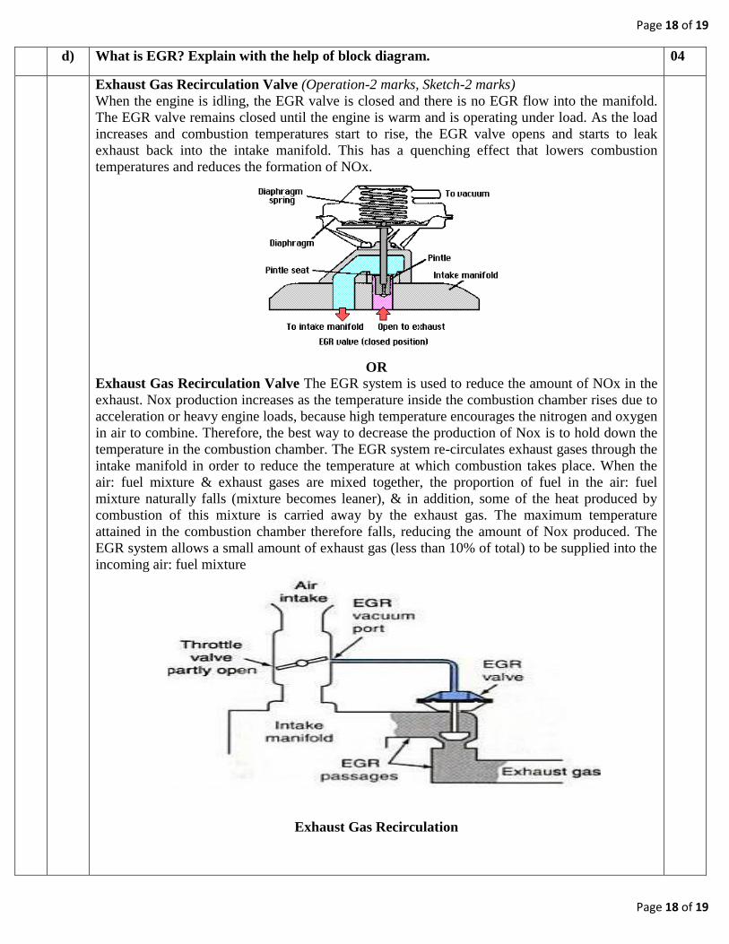
d) What is EGR? Explain with the help of block diagram. 04
Exhaust Gas Recirculation Valve (Operation-2 marks, Sketch-2 marks)
When the engine is idling, the EGR valve is closed and there is no EGR flow into the manifold.
The EGR valve remains closed until the engine is warm and is operating under load. As the load
increases and combustion temperatures start to rise, the EGR valve opens and starts to leak
exhaust back into the intake manifold. This has a quenching effect that lowers combustion
temperatures and reduces the formation of NOx.
OR
Exhaust Gas Recirculation Valve The EGR system is used to reduce the amount of NOx in the
exhaust. Nox production increases as the temperature inside the combustion chamber rises due to
acceleration or heavy engine loads, because high temperature encourages the nitrogen and oxygen
in air to combine. Therefore, the best way to decrease the production of Nox is to hold down the
temperature in the combustion chamber. The EGR system re-circulates exhaust gases through the
intake manifold in order to reduce the temperature at which combustion takes place. When the
air: fuel mixture & exhaust gases are mixed together, the proportion of fuel in the air: fuel
mixture naturally falls (mixture becomes leaner), & in addition, some of the heat produced by
combustion of this mixture is carried away by the exhaust gas. The maximum temperature
attained in the combustion chamber therefore falls, reducing the amount of Nox produced. The
EGR system allows a small amount of exhaust gas (less than 10% of total) to be supplied into the
incoming air: fuel mixture
Exhaust Gas Recirculation

Page 19 of 19
Page 19 of 19
e) Explain the effect of positive crankcase ventilation (PCV) system on engine emission. 04
(Description 2M, Sketch 2M)
PCV system: The purpose of PCV system is to remove the harmful gases from the crankcase
before damage occurs and combine them with the engine’s normal incoming air: fuel mixture.
PCV system uses a variable flow PCV valve accurately matches ventilation flow with blow-by
production characteristics. By accurately matching these two factors, crankcase ventilation
performance is optimized, while engine performance and drivability remains unaffected
positive crankcase ventilation