Embed Size (px)
Citation preview

MAHARASHTRA STATE BOARD OF TECHNICAL EDUCATION (Autonomous)
(ISO/IEC - 27001 - 2005 Certified)
__________________________________________________________________________________________________
1
WINTER– 16 EXAMINATION Model Answer Subject Code:
Important Instructions to examiners: 1) The answers should be examined by key words and not as word-to-word as given in the model answer
scheme. 2) The model answer and the answer written by candidate may vary but the examiner may try to assess the
understanding level of the candidate. 3) The language errors such as grammatical, spelling errors should not be given more Importance (Not
applicable for subject English and Communication Skills. 4) While assessing figures, examiner may give credit for principal components indicated in the figure. The
figures drawn by candidate and model answer may vary. The examiner may give credit for any equivalent figure drawn.
5) Credits may be given step wise for numerical problems. In some cases, the assumed constant values may vary and there may be some difference in the candidate’s answers and model answer.
6) In case of some questions credit may be given by judgement on part of examiner of relevant answer based on candidate’s understanding.
7) For programming language papers, credit may be given to any other program based on equivalent concept.
Q. No.
Sub Q. N.
Answer Marking Scheme
1A
a
Assumption made in air standard cycle
Following assumption made in actual cycle to analysis as air standard cycle. 1. The working fluid is perfect gas. 2. There is no change in mass of the working medium. 3. All the process that constitutes the cycle is reversible. 4. Heat is assumed to be supplied from a constant high temperature source and not from chemical reaction during the cycle. 5. There are no heat losses. 6. The working medium has constant specific heats throughout the cycle.
01 for each
17529

MAHARASHTRA STATE BOARD OF TECHNICAL EDUCATION (Autonomous)
(ISO/IEC - 27001 - 2005 Certified)
__________________________________________________________________________________________________
2
1A
b
02 for each
MAHARASHTRA STATE BOARD OF TECHNICAL EDUCATION (Autonomous)
(ISO/IEC - 27001 - 2005 Certified)
__________________________________________________________________________________________________
3
Q1A
c
d
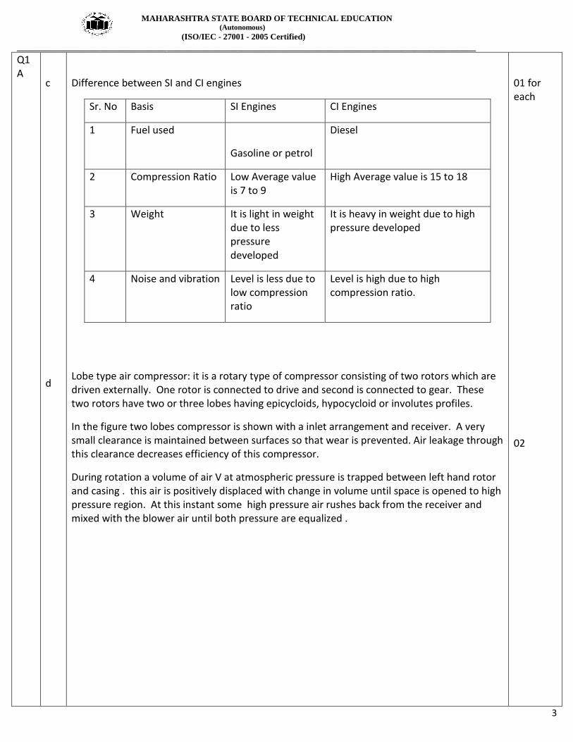
Difference between SI and CI engines
Sr. No Basis SI Engines CI Engines
1 Fuel used
Gasoline or petrol
Diesel
2 Compression Ratio Low Average value is 7 to 9
High Average value is 15 to 18
3 Weight It is light in weight due to less pressure developed
It is heavy in weight due to high pressure developed
4 Noise and vibration Level is less due to low compression ratio
Level is high due to high compression ratio.
Lobe type air compressor: it is a rotary type of compressor consisting of two rotors which are driven externally. One rotor is connected to drive and second is connected to gear. These two rotors have two or three lobes having epicycloids, hypocycloid or involutes profiles.
In the figure two lobes compressor is shown with a inlet arrangement and receiver. A very small clearance is maintained between surfaces so that wear is prevented. Air leakage through this clearance decreases efficiency of this compressor.
During rotation a volume of air V at atmospheric pressure is trapped between left hand rotor and casing . this air is positively displaced with change in volume until space is opened to high pressure region. At this instant some high pressure air rushes back from the receiver and mixed with the blower air until both pressure are equalized .
01 for each
02

MAHARASHTRA STATE BOARD OF TECHNICAL EDUCATION (Autonomous)
(ISO/IEC - 27001 - 2005 Certified)
__________________________________________________________________________________________________
4
1 B
a
02
06

MAHARASHTRA STATE BOARD OF TECHNICAL EDUCATION (Autonomous)
(ISO/IEC - 27001 - 2005 Certified)
__________________________________________________________________________________________________
5
2
b
a
Non dispersive infra red gas analyzer ( NDIR) : The working principle of infra red gas exhaust gas analyzer is as shown in figure .
It works on the principle of hetero atomic gases absorbs infra red energy at distinct and separated wavelength. The absorbed energy raises the temperature and pressure of confined gas. This enables to measure contents of hydro carbon and carbon monoxide. This is a faster method of gas analysis. The standard sample is filled in reference cell R . the sample of gas under testing is filled in cell S . The detector cell D is filled with specific gas to be measured, say CO2 . the detector cell is divided into two compartments by diaphragm. It is very sensitive. Initially infra red energy in both compartment is same and indicator reading is zero. The sample is connected to exhaust gas. This lowers pressure on sample side. It will absorb energy in proportion to concentration of CO2 in sample and detector gives percentage of CO2 present in the samp0le.
Differences between Vapour Absorption and Vapour Compression refrigeration system
N
o
Vapour Absorption system Vapour Compression System
1. Uses low grade energy like heat. Therefore,
may be worked on exhaust systems from
I.C engines, etc.
Using high-grade energy like mechanical
work.
2. Moving parts are only in the pump, which
is a small element of the system. Hence
operation is smooth.
Moving parts are in the compressor.
Therefore, more wear, tear and noise.
3. The system can work on lower evaporator
pressures also without affecting the COP.
The COP decreases considerably with
decrease in evaporator pressure.
4. No effect of reducing the load on
performance.
Performance is adversely affected at partial
loads.
5. Liquid traces of refrigerant present in
piping at the exit of evaporator
Liquid traces in suction line may damage the
compressor
6. Automatic operation for controlling the
capacity is easy.
It is difficult.
7 Charging of refrigerant is simple Charging of refrigerant is difficult
8 Part load performance is low No effect of variation of load
03
03
01 for each

MAHARASHTRA STATE BOARD OF TECHNICAL EDUCATION (Autonomous)
(ISO/IEC - 27001 - 2005 Certified)
__________________________________________________________________________________________________
6
b
02 for each
MAHARASHTRA STATE BOARD OF TECHNICAL EDUCATION (Autonomous)
(ISO/IEC - 27001 - 2005 Certified)
__________________________________________________________________________________________________
7
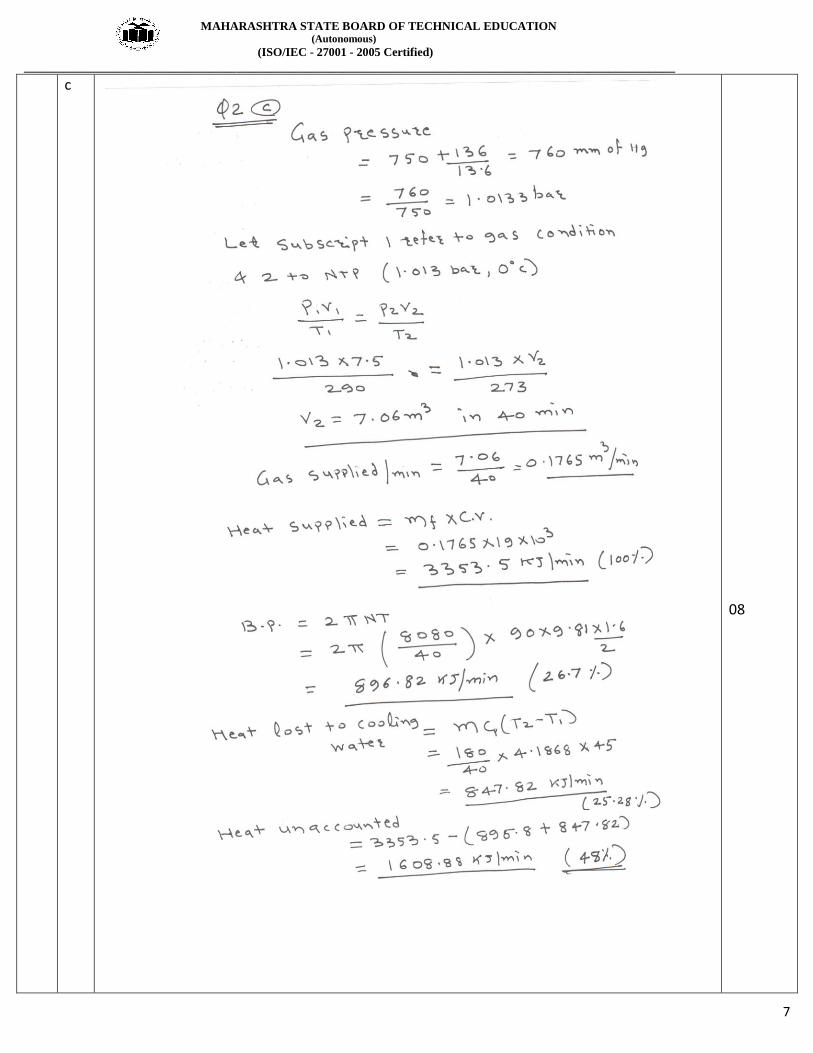
c
08
MAHARASHTRA STATE BOARD OF TECHNICAL EDUCATION (Autonomous)
(ISO/IEC - 27001 - 2005 Certified)
__________________________________________________________________________________________________
8
3
a
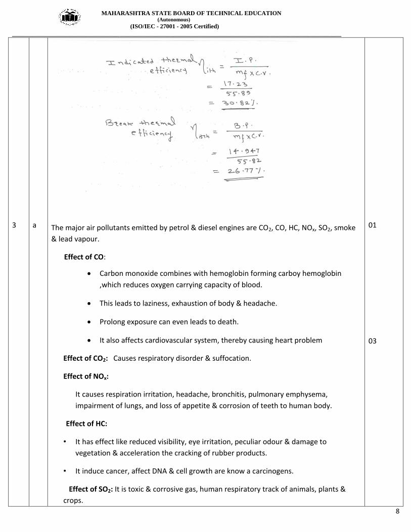
The major air pollutants emitted by petrol & diesel engines are CO2, CO, HC, NOx, SO2, smoke
& lead vapour.
Effect of CO:
Carbon monoxide combines with hemoglobin forming carboy hemoglobin
,which reduces oxygen carrying capacity of blood.
This leads to laziness, exhaustion of body & headache.
Prolong exposure can even leads to death.
It also affects cardiovascular system, thereby causing heart problem
Effect of CO2: Causes respiratory disorder & suffocation.
Effect of NOx:
It causes respiration irritation, headache, bronchitis, pulmonary emphysema,
impairment of lungs, and loss of appetite & corrosion of teeth to human body.
Effect of HC:
• It has effect like reduced visibility, eye irritation, peculiar odour & damage to
vegetation & acceleration the cracking of rubber products.
• It induce cancer, affect DNA & cell growth are know a carcinogens.
Effect of SO2: It is toxic & corrosive gas, human respiratory track of animals, plants &
crops.
01
03

MAHARASHTRA STATE BOARD OF TECHNICAL EDUCATION (Autonomous)
(ISO/IEC - 27001 - 2005 Certified)
__________________________________________________________________________________________________
9
b
c
Open cycle and closed cycle gas turbines Any four differences
Sr.n
o
Factors Open cycle gas turbine Closed cycle gas turbine
1. Pressure Lesser pressure Higher pressure
2. Size of the plant for
given output
Larger size Reduced size
3. Output Lesser output Greater output
4. Corrosion of turbine
blades
Corrosion takes place due to
contaminated gases
No corrosion since there is
indirect heating.
5. Working medium Loss of working medium No loss of working
medium.
6. Filtration of incoming
air
It may cause severe problem. No filtration of air is
required.
7. Part load efficiency Less part load efficiency More part load efficiency
8. Thermal efficiency Less thermal efficiency More thermal efficiency
9. Requirement of cooling
water
No Requirement of cooling
water
Larger amount of cooling
water required
10. Weight of system for
given power
Less More
11. Response to the
changing load
Good response Poor response
12. Fluid friction More Fluid friction Less Fluid friction
Specific humidity : It is defined as the ratio of mass of vapor to the mass of dry air in a given sample of
moist air .
It is denoted by ω
01 for each
04
MAHARASHTRA STATE BOARD OF TECHNICAL EDUCATION (Autonomous)
(ISO/IEC - 27001 - 2005 Certified)
__________________________________________________________________________________________________
10
d
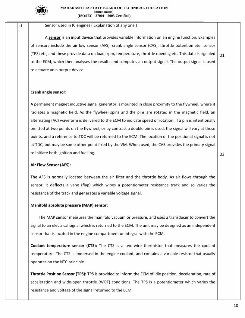
Sensor used in IC engines ( Explanation of any one )
A sensor is an input device that provides variable information on an engine function. Examples
of sensors include the airflow sensor (AFS), crank angle sensor (CAS), throttle potentiometer sensor
(TPS) etc, and these provide data on load, rpm, temperature, throttle opening etc. This data is signaled
to the ECM, which then analyses the results and computes an output signal. The output signal is used
to actuate an n output device.
Crank angle sensor:
A permanent magnet inductive signal generator is mounted in close proximity to the flywheel, where it
radiates a magnetic field. As the flywheel spins and the pins are rotated in the magnetic field, an
alternating (AC) waveform is delivered to the ECM to indicate speed of rotation. If a pin is intentionally
omitted at two points on the flywheel, or by contrast a double pin is used, the signal will vary at these
points, and a reference to TDC will be returned to the ECM. The location of the positional signal is not
at TDC, but may be some other point fixed by the VM. When used, the CAS provides the primary signal
to initiate both ignition and fuelling.
Air Flow Sensor (AFS):
The AFS is normally located between the air filter and the throttle body. As air flows through the
sensor, it deflects a vane (flap) which wipes a potentiometer resistance track and so varies the
resistance of the track and generates a variable voltage signal.
Manifold absolute pressure (MAP) sensor:
The MAP sensor measures the manifold vacuum or pressure, and uses a transducer to convert the
signal to an electrical signal which is returned to the ECM. The unit may be designed as an independent
sensor that is located in the engine compartment or integral with the ECM.
Coolant temperature sensor (CTS): The CTS is a two-wire thermistor that measures the coolant
temperature. The CTS is immersed in the engine coolant, and contains a variable resistor that usually
operates on the NTC principle.
Throttle Position Sensor (TPS): TPS is provided to inform the ECM of idle position, deceleration, rate of
acceleration and wide-open throttle (WOT) conditions. The TPS is a potentiometer which varies the
resistance and voltage of the signal returned to the ECM.
01
03

MAHARASHTRA STATE BOARD OF TECHNICAL EDUCATION (Autonomous)
(ISO/IEC - 27001 - 2005 Certified)
__________________________________________________________________________________________________
11
4A
e
a
From the voltage returned, the ECM is able to calculate idle position, full-load and also how
quickly the throttle is opened.
Oxygen sensor (OS): An oxygen sensor is a ceramic device 'placed in the exhaust manifold on the
engine side of the catalytic converter. The oxygen sensor returns a signal to the ECM, which can almost
instantaneously (within 50 ms) adjust the injection duration.
Scavenging :
In two stroke engines , at the end of expansion stroke, combustion chamber is full of products of combustion. This is due to elimination of exhaust stroke like in four stroke engine. Scavenging is the process of clearing the cylinder after the expansion stroke. This is done short duration of time available between end of expansion and start of charging process.
Types of scavenging :
1. Uniflow scavenging process
2. Cross scavenging process
3. Loop or reverse scavenging process
Combustion in CI Engines :The combustion in CI engines is taking place in following stages as shown in figure
1. Ignition delay period: During this period, some fuel has been admitted but not yet ignited. The delay period is a sort of preparatory phase. It is counted from the start of
injection to the point where P-ɵ curve separates from air compression curve.
2. Rapid or uncontrolled combustion : In this stage , the pressure rises rapid because during the delay period the fuel droplets have time to spray and have fresh air around them. This period is counted from end of delay period to the max pressure on indicator diagram.
3. Controlled combustion : uncontrolled combustion is followd by controlled combustion stage. The period of this stage assumed to be at the end of max cycle temperature.
4. After burning : It is expected to end combustion process after third stage. Because of poor distribution of fuel particles combustion still continues during remaining part of expansion stroke. This is after burning .
02
02
02

MAHARASHTRA STATE BOARD OF TECHNICAL EDUCATION (Autonomous)
(ISO/IEC - 27001 - 2005 Certified)
__________________________________________________________________________________________________
12
b
Battery Ignition system : It consists of a battery of 6 or 12 volts, ignition switch, induction coil, condenser, distributor and a circuit breaker. One terminal of battery is ground to the frame of the engine and other is connected through the ignition switch to one primary terminal of the ignition coil . The other terminal is connected to one end of contact points of the circuit breaker.
To start with the ignition switch is made on and the engine is cranked. The contacts touch, the current flows from battery through the switch. A condenser connected across the terminals of the contact breaker points prevent the sparking at these points. The rotating cam breaks open the contacts immediately and breaking of this primary circuit brings about a change in the magnetic fields and voltage changes from 12 to 12000 V. due to the high voltage. The spark jumps across the gap in the spark plug and air fuel mixture is ignited in the cylinder
02
02
02
MAHARASHTRA STATE BOARD OF TECHNICAL EDUCATION (Autonomous)
(ISO/IEC - 27001 - 2005 Certified)
__________________________________________________________________________________________________
13
c
d
Bharat stage III and IV norms :
Petrol Emission Norms (All figures in g/km)
Emission Norm CO HC NOx HC+NOx PM
BS-III 2.30 0.20 0.15 --- ---
BS-IV 1.00 0.10 0.08 --- ---
Diesel Emission Norms (All figures in g/km)
Emission Norm CO HC NOx HC+NOx PM
BS-III 0.64 --- 0.50 0.56 0.05
BS-IV 0.50 --- 0.25 0.30 0.025
CO emissions are Carbon Monoxide emissions are are more evident in Petrol engines. Long Term
exposure can prevent oxygen transfer and increase headaches/nausea.
HC emissions are Hydrocarbons which are again more prevalent in Petrol engines. Short term exposure
can cause headaches, vomiting and disorientation.
NOx emissions are Nitrogen Oxide emissions which are more prevalent in Diesel engines. Long Term
exposure can cause Nose and eye irritation and damage lung tissue.
PM is Particulate matter, again more prevalent in a Diesel engine. Long Term exposure can harm the
respiratory tract and reduce lung function.
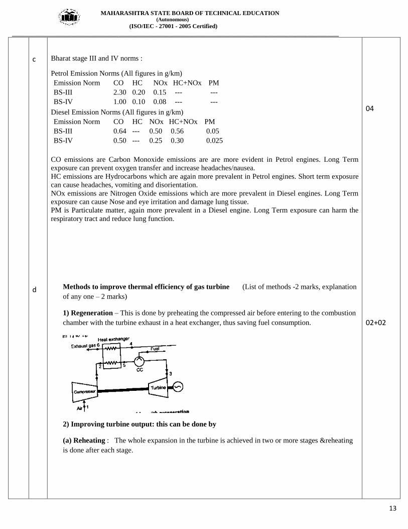
Methods to improve thermal efficiency of gas turbine (List of methods -2 marks, explanation
of any one – 2 marks)
1) Regeneration – This is done by preheating the compressed air before entering to the combustion
chamber with the turbine exhaust in a heat exchanger, thus saving fuel consumption.
2) Improving turbine output: this can be done by
(a) Reheating : The whole expansion in the turbine is achieved in two or more stages &reheating
is done after each stage.
04
02+02

MAHARASHTRA STATE BOARD OF TECHNICAL EDUCATION (Autonomous)
(ISO/IEC - 27001 - 2005 Certified)
__________________________________________________________________________________________________
14
4B
a
(b) Increasing the value of maximum cycle temp.
(c) Improving turbine efficiency by improving design.
3. Reducing compressor input: By
(a) Intercooling : Compressor work is reduced by intercooling the air between the compressor
stages.
(b)By lowering inlet temp to compressor
(c) By increasing compressor efficiency
(d) Water injection at inlet to compressor
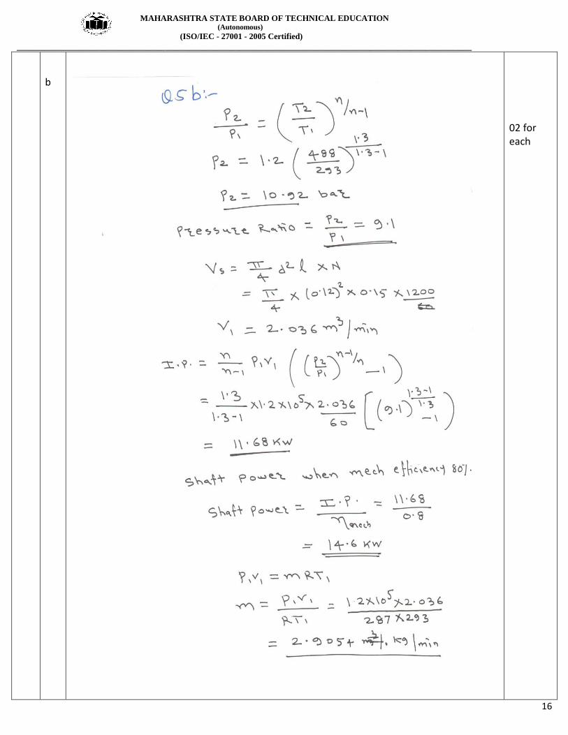
i) Indicated Power (ip) is defined as the power developed by combustion of fuel in the
cylinder of engine. It is always more than brake power.
ii) Mechanical efficiency : ηm : It is a measure of mechanical perfection of the engine or its ability to
transmit power developed in the engine cylinder to the crank shaft . It is defined as the ratio of brake
power to indicated power of the engine
iii) B.S.F.C: It is the weight of fuel required to develop 1KW of the brake power for period of 1
hour. Unit of B.S.F.C is Kg/KW h.
It is defined as the amount of fuel consumed per unit of break power developed per hour.
B.S.F.C =
02
02
02
MAHARASHTRA STATE BOARD OF TECHNICAL EDUCATION (Autonomous)
(ISO/IEC - 27001 - 2005 Certified)
__________________________________________________________________________________________________
15
5
b
a
Additives (any six )
(1) Detergents – To keep engine parts, such as piston and piston rings, clean & free from deposits.
(2) Dispersants – To suspend & disperse material that could form varnishes, sludge etc that clog the
engine.
(3) Anti – wear – To give added strength & prevent wear of heavily loaded surfaces such as crank shaft
rods & main bearings.
(4) Corrosion inhibitors – To fight the rust wear caused by acids moisture. Protect vital steel & iron
parts from rust & corrosion.
(5) Foam inhibitors – control bubble growth, break them up quickly to prevent frothing & allow the oil
pump to circulate oil evenly.
(6)Viscosity index improver – added to adjust the viscosity of oil.
(7) Pour point depressant - improves an oil ability to flow at very low temperature.
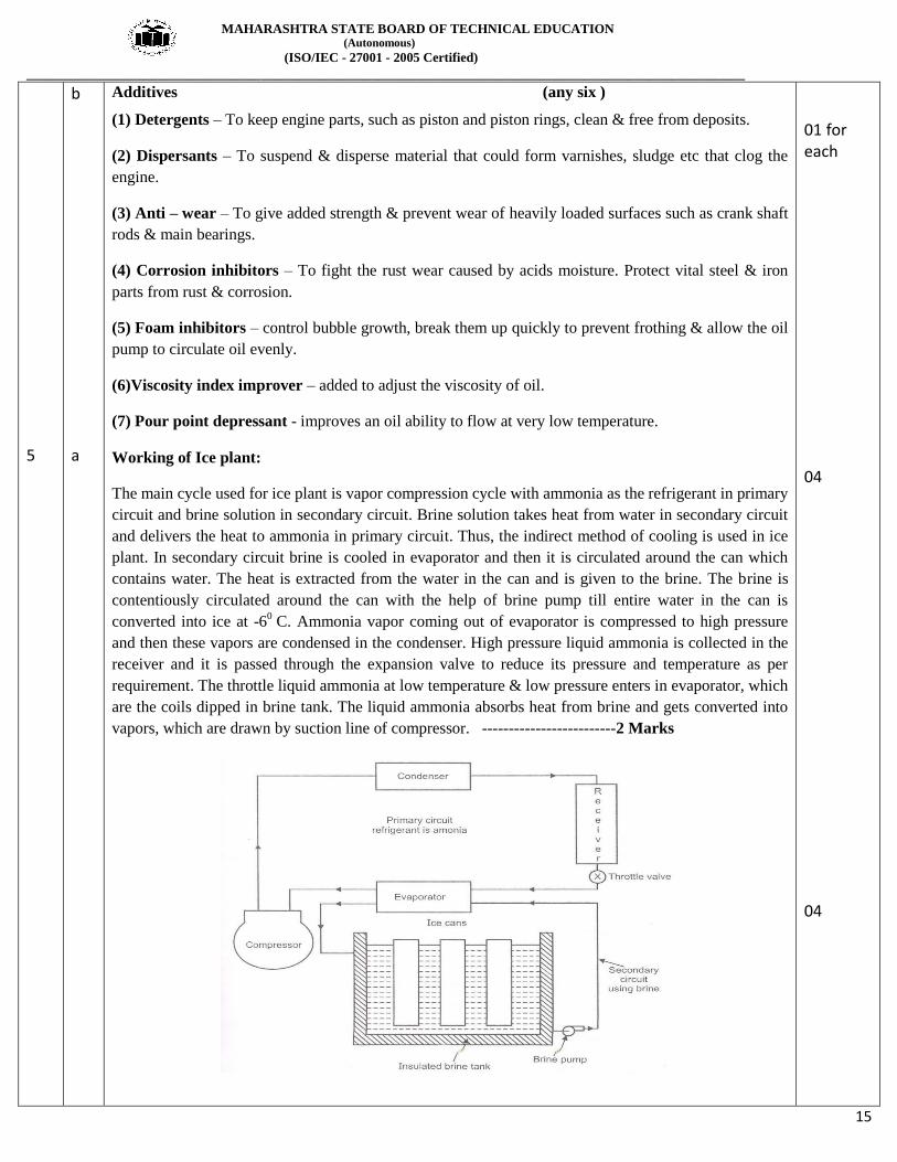
Working of Ice plant:
The main cycle used for ice plant is vapor compression cycle with ammonia as the refrigerant in primary
circuit and brine solution in secondary circuit. Brine solution takes heat from water in secondary circuit
and delivers the heat to ammonia in primary circuit. Thus, the indirect method of cooling is used in ice
plant. In secondary circuit brine is cooled in evaporator and then it is circulated around the can which
contains water. The heat is extracted from the water in the can and is given to the brine. The brine is
contentiously circulated around the can with the help of brine pump till entire water in the can is
converted into ice at -60
C. Ammonia vapor coming out of evaporator is compressed to high pressure
and then these vapors are condensed in the condenser. High pressure liquid ammonia is collected in the
receiver and it is passed through the expansion valve to reduce its pressure and temperature as per
requirement. The throttle liquid ammonia at low temperature & low pressure enters in evaporator, which
are the coils dipped in brine tank. The liquid ammonia absorbs heat from brine and gets converted into
vapors, which are drawn by suction line of compressor. -------------------------2 Marks
01 for each
04
04
MAHARASHTRA STATE BOARD OF TECHNICAL EDUCATION (Autonomous)
(ISO/IEC - 27001 - 2005 Certified)
__________________________________________________________________________________________________
16
b
02 for each
MAHARASHTRA STATE BOARD OF TECHNICAL EDUCATION (Autonomous)
(ISO/IEC - 27001 - 2005 Certified)
__________________________________________________________________________________________________
17
6
c
a
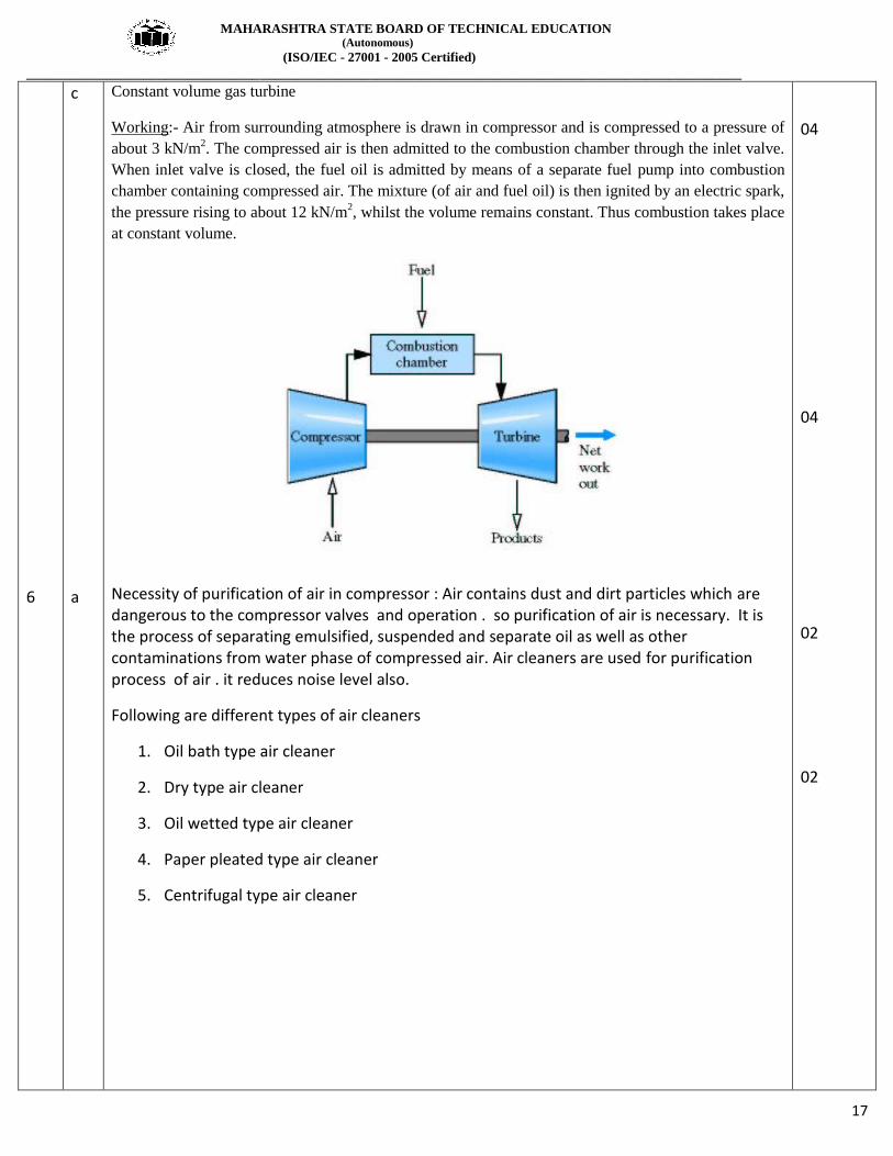
Constant volume gas turbine
Working:- Air from surrounding atmosphere is drawn in compressor and is compressed to a pressure of
about 3 kN/m2. The compressed air is then admitted to the combustion chamber through the inlet valve.
When inlet valve is closed, the fuel oil is admitted by means of a separate fuel pump into combustion
chamber containing compressed air. The mixture (of air and fuel oil) is then ignited by an electric spark,
the pressure rising to about 12 kN/m2, whilst the volume remains constant. Thus combustion takes place
at constant volume.
Necessity of purification of air in compressor : Air contains dust and dirt particles which are dangerous to the compressor valves and operation . so purification of air is necessary. It is the process of separating emulsified, suspended and separate oil as well as other contaminations from water phase of compressed air. Air cleaners are used for purification process of air . it reduces noise level also.
Following are different types of air cleaners
1. Oil bath type air cleaner
2. Dry type air cleaner
3. Oil wetted type air cleaner
4. Paper pleated type air cleaner
5. Centrifugal type air cleaner
04
04
02
02

MAHARASHTRA STATE BOARD OF TECHNICAL EDUCATION (Autonomous)
(ISO/IEC - 27001 - 2005 Certified)
__________________________________________________________________________________________________
18
b
c
i) DPT – Dew point temperature tDP
- It is the temperature at which air water vapour mixture starts to condense.
D.P.T. of mixture is defined as the temperature at which water vapours starts to condense.
Ii) WBT - Wet bulb temperature - tWB - It is the temperature recorded by thermometer when its bulb is covered with wet cloth known as wick and is exposed to air.
04
02
02

MAHARASHTRA STATE BOARD OF TECHNICAL EDUCATION (Autonomous)
(ISO/IEC - 27001 - 2005 Certified)
__________________________________________________________________________________________________
19
d
e
Ram jet – (Fig – 2 marks ; explanation –2 marks)
- Ram jet is also called as ‘Athodyd or flying stove pipe’.
- It is a steady combustion or continuous flow engine & has the simplest construction of any propulsion
engine.
- Consist of inlet diffuser, combustion chamber & exit nozzle.
- Air entering into ram jet with supersonic speed is slowed down to sonic speed in supersonic diffuser,
increasing air pressure.
- The air pressure is further increased in the subsonic diffuser.
- The fuel injected into the combustion chamber is burned with the help of flame stabilizers. The high
temp & high pressure gases are passed through the nozzle converting the pressure energy into kinetic
energy.
- It is not self operating at zero flight velocity. It requires launching rockets.
Split Air-conditioner labeled Diagram 02 for figure 02 for labeling
02
02
04

MAHARASHTRA STATE BOARD OF TECHNICAL EDUCATION (Autonomous)
(ISO/IEC - 27001 - 2005 Certified)
__________________________________________________________________________________________________
20


![(ISO/IEC - 27001 - 2005 Certified)msbte.engg-info.website/sites/default/files/w16mo 6/17618_winter_2… · wait until the wheels stop moving. [7] Don’t touch the rotating wheels,](https://img.dokumen.tips/doc/110x75/5f35c72c3ed4401f69723e5a/isoiec-27001-2005-certifiedmsbteengg-infowebsitesitesdefaultfilesw16mo.jpg)


![APOSTILA TEOLOGIA 2015/1 – FIT 1500 A05 [Nutrição]professor.pucgoias.edu.br/SiteDocente/admin/arquivosUpload/17529/... · Força da razão, rudimentos da ciência inventando técnicas](https://img.dokumen.tips/doc/110x75/5be6a8b209d3f2580c8de33c/apostila-teologia-20151-fit-1500-a05-nutricao-forca-da-razao-rudimentos.jpg)