Embed Size (px)
Citation preview

MAHARASHTRA STATE BOARD OF TECHNICAL EDUCATION
(Autonomous)
(ISO/IEC-27001-2005 Certified)
Winter – 2016 Examinations
Model Answers Subject Code: 17640 (MET)
Page No: 1 of 16
Important Instructions to examiners:
1) The answers should be examined by key words and not as word-to-word as given in the model
answer scheme.
2) The model answer and the answer written by candidate may vary but the examiner may try to
assess the understanding level of the candidate.
3) The language errors such as grammatical, spelling errors should not be given importance (Not
applicable for subject English and Communication Skills).
4) While assessing figures, examiner may give credit for principal components indicated in the
figure. The figures drawn by candidate and model answer may vary. The examiner may give
credit for any equivalent figure/figures drawn.
5) Credits may be given step wise for numerical problems. In some cases, the assumed constant
values may vary and there may be some difference in the candidate’s answers and model
answer (as long as the assumptions are not incorrect).
6) In case of some questions credit may be given by judgment on part of examiner of relevant
answer based on candidate’s understanding.
7) For programming language papers, credit may be given to any other program based on
equivalent concept

MAHARASHTRA STATE BOARD OF TECHNICAL EDUCATION
(Autonomous)
(ISO/IEC-27001-2005 Certified)
Winter – 2016 Examinations
Model Answers Subject Code: 17640 (MET)
Page No: 2 of 16
1 a) Attempt any THREE of the following: 12
1 a) i) Draw neat labelled layout of feeding posts.
Ans:
Layout of feeding posts:
Fully
Labeled 4
marks,
Partially
labeled 3 to
2 marks,
Unlabeled 1
to 2 marks
1 a) ii) Give any four advantages of remote control systems.
Ans:
Advantages of remote control systems:
1) As substations and control posts are unattended (due to remote controls)
there is considerable savings due to less manpower.
2) Supervision of all functions of all individual posts of the route from a
central control station is easy. Hence complete coordination over entire
system is possible.
3) As oral instructions are very less, human error based problems are less.
4) Correct and rapid supervision about execution of instruction is possible.
5) Switching operations are carried out safely, quickly, and economically.
6) Maintenance cost is low.
1 mark each
(any four)
= 4 marks
1 a) iii) Explain with neat sketch the four aspects of colour light signalling.
Ans:
Four aspects of colour light signal:
4th
aspect is attention aspect given by 2 yellow lights in vertical fashion
interpreted as “prepared to pass next signal at restricted speed”.
signal1 & 2 located less than braking distance apart. Signal 3 shows
attention aspect, when signal 2 is at caution.
a driver sighting signal 3, must pass signal 2 at restricted speed, stop has
to be made at signal 1.
1 mark
1 mark
1 mark
1 mark

MAHARASHTRA STATE BOARD OF TECHNICAL EDUCATION
(Autonomous)
(ISO/IEC-27001-2005 Certified)
Winter – 2016 Examinations
Model Answers Subject Code: 17640 (MET)
Page No: 3 of 16
1 a) iv) Give the purpose and location of neutral section and section insulator.
Ans:
Neutral section: Purpose - Passing of pantograph under insulated overlap will cause short circuit
between two phases, damaging OHE & pantograph. To avoid this bridging a
neutral section is inserted between them.
Location - Located between two substations.
Section insulator: Purpose - Section insulators are provided to insulate OHE of one elementary
section from the OHE of another adjacent elementary section.
Location - Located at cross over from one track to other, from main line to siding.
1 mark each
for purpose
= 1x2=
2marks
1 mark each
for location
= 1x2=
2marks
1 b) Attempt any ONE of the following: 6
1 b) i) With neat sketch explain automatic weight tension and temperature compensation.
Ans:
Automatic weight tension and temperature compensation:
The tension in overhead lines in traction systems depends on the temperature.
Higher temperatures lead to expansion of conductors and hence sag. It is therefore
necessary to minimize the sag to least by giving more tension to the conductors.
This adjustment of tension and sag is done automatically to facilitate sparkless
collection of current from the overhead lines by the current collectors mounted on
the top of high speed loco. It works as follows.
The tensioning device consists of pulley block or a winch with suitable reduction
ratio. This arrangement is made on the two sides of the tensioned catenary and
contact wire. With variations in the temperature the tension in the contact wire and
catenary are maintained due to the pull of the counter weights of around 400 kg
shown in the figure. The tension in the contact wire and catenary is around 1000
kg.
Description
3 marks
+
Diagram
3 marks
= 6 marks

MAHARASHTRA STATE BOARD OF TECHNICAL EDUCATION
(Autonomous)
(ISO/IEC-27001-2005 Certified)
Winter – 2016 Examinations
Model Answers Subject Code: 17640 (MET)
Page No: 4 of 16
1 b) ii) With neat diagram explain systems of remote control.
Ans:
Used on sections employing electrification at 25 kV.
Operates on voice frequency signaling.
In this coded dc pulses carrying information are made to modulate carrier
currents at voice frequencies between 420 to 2560 Hz.
These have 18 channels.
18 stations can be controlled by one pair of wires.
Avoids magnetically induced disturbances.
This is extensively used on ac electrified tracks.
One pair carries tele-commands from RCC to control post.
Other pair carries tele-signals from CP to RCC.
Induction effects of the 25 kV ac are to be overcome by isolation
transformers.
Repeater stations are provided at regular intervals of about 45 to 50 km.
1 mark for
each of any
four points
=
4 marks
+
2 marks for
figure
=
6 marks
2 Attempt any FOUR of the following: 16
2 a) Explain the purpose of elementary section in supply system.
Ans:
Purpose of elementary section:
The subsection distance of 10 km to 15 km is too large to carry out repairs
in case of faults.
Maintenance is time consuming.
To ensure rapid isolation of fault on OHE and facilitate repairs each
subsection is further divided into elementary sections.
Adjacent elementary subsections are separated by insulated overlap
bridged by isolators which are manually operated on no load.
1 mark for
each point
2 b) State any four points which are considered while deciding the span length in
overhead equipment.
Ans:
Points considered while deciding the span length in overhead equipment:
1) Maximum wind pressure on contact wire. (98 kg/sq.m for coastal areas to
74 kg/sq.m for interiors,) Higher the pressure lower is the span.
2) Curvature of paths: low span for curves.
3) Track layout and other local conditions such as restricted head room etc.
1 mark each
(any 4)

MAHARASHTRA STATE BOARD OF TECHNICAL EDUCATION
(Autonomous)
(ISO/IEC-27001-2005 Certified)
Winter – 2016 Examinations
Model Answers Subject Code: 17640 (MET)
Page No: 5 of 16
4) Current collection requirements necessitate lower spans.
5) Adjacent spans should not differ by more than 18 m.
6) Span lengths are in multiples of 4.5 m and vary from 27 m to 72 m.
2 c) Explain with neat diagram the working of the double battery parallel block system
in train lighting.
Ans:
Double battery parallel block system for train lighting:
When train is stationary or runs slowly, generator contacts B1 and B2 are
open and both batteries supply the load through closed contacts L1 and L2,
short circuiting lamp resistance D as shown in fig (a).
Fig. (a)
When train is in motion and lights on, generator is connected to battery 1
through closed contact B1 and lighting load is connected to battery 2
through closed contact L2, as shown in fig (b).
Fig. (b)
When train is in motion and lighting and other loads are switched off,
switches L1 and L2 are open, lamp resistance D is short circuited when
both generator contacts B1 and B2 are closed and both batteries will then
be charged in parallel.
1 mark
1 mark
1 mark
1 mark

MAHARASHTRA STATE BOARD OF TECHNICAL EDUCATION
(Autonomous)
(ISO/IEC-27001-2005 Certified)
Winter – 2016 Examinations
Model Answers Subject Code: 17640 (MET)
Page No: 6 of 16
2 d) State the function of contactors in electric locomotive. List different types of
contactors for the same with its purpose.
Ans:
Function of contactors:
Contactor in electric locos is a switch which makes and breaks a power circuit on
load and is remotely controlled.
Different contactors used in electric locomotives and their purpose:
1) Electromagnetic –used for circuits of low currents as auxiliary motors.
2) Electro pneumatic –used for heavy power currents as traction motors.
3) Cam & roller operated –used for group switching.
1 mark
½ mark for
each type
½ mark for
each
function
2 e) Draw a neat schematic diagram of earth fault protection of power and auxiliary
circuits.
Ans:
i) Earth fault protection for power circuit in Loco:
2 marks

MAHARASHTRA STATE BOARD OF TECHNICAL EDUCATION
(Autonomous)
(ISO/IEC-27001-2005 Certified)
Winter – 2016 Examinations
Model Answers Subject Code: 17640 (MET)
Page No: 7 of 16
ii) Earth fault protection for auxiliary circuit in Loco:
2 marks
3 Attempt any FOUR of the following: 16
3 a) What are the weaknesses of LIM propelled railway traction system?
Ans:
Weaknesses of LIM propelled railway traction system:
1) The system requires laying of reaction rail of Al plate backed by mild
steel all along the route. This considerably adds to the cost of track.
2) Since Al is relative expensive material, chances of theft are more,
hence disruption of service.
3) Due to more air gap in LIM than RIM, pf is poor and increased motor
losses.
4) Due to discontinuity in the magnetic and electric circuits at entry and
exit ends of motor, motor efficiency is poor.
5) Additional cost for inverter etc.
1 mark each
(any four)
= 4 marks
3 b) Give protection scheme used for 25 kV catenary protection for AC traction.
Ans:
Protection scheme used for 25 kV catenary protection for AC traction:
As shown in the figure below the scheme consists of
1) MHO relay that makes use of the impedance phase angle to get proper
discrimination for distant faults on it. It consists of PT, CT on 25 kV
catenary and variable capacitors for phase angle adjustment.
2) Over current relay.
3) Under voltage relay for low voltage protection.
2 marks for
description.

MAHARASHTRA STATE BOARD OF TECHNICAL EDUCATION
(Autonomous)
(ISO/IEC-27001-2005 Certified)
Winter – 2016 Examinations
Model Answers Subject Code: 17640 (MET)
Page No: 8 of 16
2 marks for
figure
3 c) With neat diagram explain trolley collector or pole collector for overhead system.
Ans:
Trolley collector for overhead system:
This consists of a grooved gun metal wheel or grooved slider shoe with
carbon insert carried attached to the end of a long pole provided on the top
of the car.
Other end of this pole is hinged to a swiveling base fixed to roof of
vehicle.
Necessary upward pressure for the pole and current collector is achieved
by means of springs.
As two trolley wires are required for a trolley bus a separate trolley
collector is provided for each wire, the bases being mounted side by side.
The pressure for wheel is approximately 10kg and for a carbon insert
slider is approximately 17kg.
The main drawback of trolley collector is that it has to be rotated through
180° for reversing the direction of motion of the vehicle.
Another drawback is that there is poor contact between the wheel and
trolley wire which gives rise to high current density.
Suitable for comparative low speed (say 22 to 30 kmph).
1 mark for
each point
(any three)
+
1 mark for
figure.

MAHARASHTRA STATE BOARD OF TECHNICAL EDUCATION
(Autonomous)
(ISO/IEC-27001-2005 Certified)
Winter – 2016 Examinations
Model Answers Subject Code: 17640 (MET)
Page No: 9 of 16
3 d) State any four factors by which locations and spacing of substations are decided.
Ans:
Factors by which locations and spacing of substations are decided:
1) System voltage: For identical percentage voltage drops, system voltage is
greater and hence allowable resistance is more and hence the substations
can be placed at higher distances.
2) Availability of HT grid lines: If easily available, nearby voltage
fluctuations are less and hence distances between substations can be
increased.
3) Availability of land: Proximity of land to stations or railway owned lands.
4) Losses in track conductor system: Higher distances lead to higher losses.
5) Maximum permissible voltage drop: Greater spacing leads to higher drops.
6) Overload current setting of track feeder: For large spacing, the resistance
of feeder is large and the tripping may not occur due to insufficient current
even though fault has occurred.
1 mark each
(any four)
3 e) What are the ratings of circuit breaker used in traction substation?
Ans:
Ratings of circuit breaker used in traction substation:
Low oil content type, capable of being operated manually and by remote, 25 kV
Rated capacity of 750 A,
Rupturing capacity 500 MVA, and
Overall tripping time 0.14 seconds.
1 mark
1 mark
1 mark
1 mark
4 a) Attempt any THREE of the following: 12
4 a) i) What is importance of contact wire gradient in OHE?
Ans:
Importance of contact wire gradient:
When OHE passes under an over line structure, the contact wire height is
to be reduced.
Height of OHE is increased at level crossing.
The change-over is achieved very gradually depending on the speed of the
pantograph.
Else pantograph may lose contact or excessive pressure may be exerted on
contact wire.
Higher the running speed smaller should be the gradient.
The gradient should not be too much; else the system will be disturbed.
Gradient of 4 mm per meter for speeds up-to 100 kmph.
Gradient of 3 mm per meter for speeds above 100 kmph.
Gradient of 10 mm per meter for siding is allowed.
1 mark for
each point
(any four)

MAHARASHTRA STATE BOARD OF TECHNICAL EDUCATION
(Autonomous)
(ISO/IEC-27001-2005 Certified)
Winter – 2016 Examinations
Model Answers Subject Code: 17640 (MET)
Page No: 10 of 16
4 a) ii) Draw diagram of DC track circuit where DC track are to be used.
Ans:
Diagram of DC track circuit where DC track are to be used:
Fully
Labeled 4
marks
Partially
labeled
3 to 2
marks,
Unlabeled
1 to 2 marks
4 a) iii) Compare diamond type pantograph and faiveley type pantograph (any four points)
Ans:
Comparison diamond and faiveley type pantograph:
Particulars Diamond pantograph Faiveley pantograph
Contact Pressure Higher Lower
Weight Higher Lower
Current capacity Higher Lower
Maintenance More Low
Cost Higher Lower
Currents handled Higher Lower
1 mark for
each point
(any four)
4 a) iv) Define and give normal values of the following terms used in OHE:
i) Encumbrance ii) Stagger.
Ans:
i) Encumbrance: It is the axial distance between catenary and contact wire.
It is 1.4 m normally.
ii) Stagger: It is the distance between contact wire and pantograph axis.
Range is 675 mm to 800 mm in worst conditions.
1 mark
1 mark
1 mark
1 mark
4 b) Attempt any ONE of the following: 6
MAHARASHTRA STATE BOARD OF TECHNICAL EDUCATION
(Autonomous)
(ISO/IEC-27001-2005 Certified)
Winter – 2016 Examinations
Model Answers Subject Code: 17640 (MET)
Page No: 11 of 16
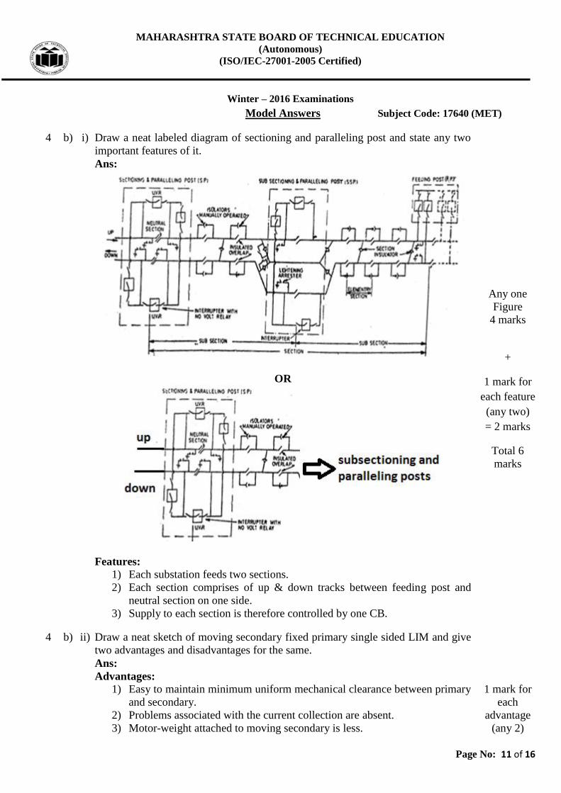
4 b) i) Draw a neat labeled diagram of sectioning and paralleling post and state any two
important features of it.
Ans:
OR
Features:
1) Each substation feeds two sections.
2) Each section comprises of up & down tracks between feeding post and
neutral section on one side.
3) Supply to each section is therefore controlled by one CB.
Any one
Figure
4 marks
+
1 mark for
each feature
(any two)
= 2 marks
Total 6
marks
4 b) ii) Draw a neat sketch of moving secondary fixed primary single sided LIM and give
two advantages and disadvantages for the same.
Ans:
Advantages:
1) Easy to maintain minimum uniform mechanical clearance between primary
and secondary.
2) Problems associated with the current collection are absent.
3) Motor-weight attached to moving secondary is less.
1 mark for
each
advantage
(any 2)

MAHARASHTRA STATE BOARD OF TECHNICAL EDUCATION
(Autonomous)
(ISO/IEC-27001-2005 Certified)
Winter – 2016 Examinations
Model Answers Subject Code: 17640 (MET)
Page No: 12 of 16
4) Low energy consumption.
Disadvantages:
1) Track cost is very high due to expensive primary.
2) High utilization factor of the track is required.
3) Low efficiency.
1 mark for
each
disadvantag
e(any 2)
Figure 2
marks
=Total 6
marks
5 Attempt any TWO of the following: 16
5 a) With a neat diagram explain the method of obtaining unidirectional polarity in
train lighting.
Ans:
Method of obtaining unidirectional polarity in train lighting:
Dynamo has rocker arm mounted on the shaft, on friction tight. When the direction
of rotation of the shaft is clockwise, terminal X will be positive and terminal Y
will be negative. This will make X brush to touch brush P1 while terminal Y to
touch brush N. Thus, gives the output polarity as shown in figure.
When the direction of rotation is anticlockwise, X brush will have negative
polarity and Y brush have positive polarity. X terminal of the rocker arm will
touch to N1 brush and Y terminal of the rocker arm will touch P brush. Thus, the
output polarities will be obtained as shown in figure which remains unchanged.
Thus, unidirectional polarity is obtained in train lighting.
Figure 4
marks
2 marks
2 marks

MAHARASHTRA STATE BOARD OF TECHNICAL EDUCATION
(Autonomous)
(ISO/IEC-27001-2005 Certified)
Winter – 2016 Examinations
Model Answers Subject Code: 17640 (MET)
Page No: 13 of 16
5 b) Draw the schematic arrangement of power supply for auxiliary circuit. Explain
briefly the functions and main features of equipment in auxiliary circuit.
Ans:
Schematic arrangement of power supply for auxiliary circuit:
Auxiliary circuit equipment with function and features:
1) Arno convertor, produces three phase from single phase
2) Battery to run baby compressor which supplies air for initial raising of
pantograph and closing of air blast circuit breaker.
3) Head light, marker light, flasher light.
4) DC generator coupled to Arno convertor or battery charger for DC.
5) Blowers used for traction motors, rectifiers, transformer.
6) Pumps: Oil pump: transformer oil pump, water pump etc
7) Air compressor – operation of air control and application of brakes
8) Exhausters for vacuum brake.
9) Fan – cab ventilation
10) Heater – locomotive heating
Figure 4
marks.
Functions
and features
any four
1 mark each
= 4 marks ,
Total 8
marks
5 c) What are the practical possibilities of LIM propelled transportation?
Ans:
Practical possibilities of LIM propelled transportation:
1. For movement of pedestrians in the city centers along straight / circular
platforms.
2. Along high density routs.
3. As moving platforms.
4. People moving system.
5. Predefined water routes.
6. For crossing rivers.
7. Surface transportation.
8. Underground transportation.
9. Overhead transportation.
10. In hilly areas as ropeways.
11. Moving between fixed points.
1 mark each
(any eight )

MAHARASHTRA STATE BOARD OF TECHNICAL EDUCATION
(Autonomous)
(ISO/IEC-27001-2005 Certified)
Winter – 2016 Examinations
Model Answers Subject Code: 17640 (MET)
Page No: 14 of 16
6 Attempt any TWO of the following: 16
6 a) Explain the purpose of the following equipment in AC locomotive,
i) Batteries ii) Flasher lights iii) Arno convertor iv) Blowers.
Ans:
Purpose of given equipment in AC locomotive:
i) Batteries: To run baby compressor which supplies air for initial raising
of pantograph and closing of air blast circuit breaker. Provides lighting in
the drivers cabin.
ii) Flasher lights: Locomotives have a flasher lamp for use in emergencies or
special circumstances. This is usually amber or yellow, and mounted close
to (usually on the right side) of the headlight near roof level, or on the edge
of the roof. Recently LED flashers have come into use.
iii) Arno convertor: converts single phase supply to three phase supply
varying from 290 Volts to 460 Volts. It is used for supplying some of the
auxiliary equipment in the locomotive.
iv) Blowers: Blowers used for cooling of traction motors, rectifiers,
smoothing reactors and for transformers.
2 marks
each
6 b) i) Give meaning of the term defect in a locomotive. Also give classification of it and
methods to eliminate them.
Ans:
Defect in a locomotive:
Defect – failure in general sense can be regarded as defect which results in
reduction in speed or load capacity of Locomotive.
Classified by their causes –
1) Out of defective design , material or workmanship by the manufacturer
2) Out of inadequate maintenance due to the negligence on the part of
maintenance staff.
3) Out of the lacuna in maintenance schedules which may necessiate change
in the periodicity of inspection.
For elimination of the defects under (i) above , appropriate action is to be taken by
the manufacturer and defects under (ii) & (iii) can be minimised by resorting to the
ideal maintenance practice.
1 mark
2 mark
1 mark
6 b) ii) Give the broad classification of maintenance of a locomotive and briefly explain
each type.
Ans:
1) Preventive maintenance:
Advance actions have to be taken to ward off future failures.
Cleaning of the whole system.
Checks and adjustments as per manual for correct functioning.
Lubrications of moving parts.
Replacement of fast wearing parts.
2) Corrective maintenance:
General over haul for wear and tear in service locos.
Identification of highly stressed / corroded / deteriorated parts for
Classificatio
n 1 mark,
1 mark for
each type
explanation
= 3 marks,

MAHARASHTRA STATE BOARD OF TECHNICAL EDUCATION
(Autonomous)
(ISO/IEC-27001-2005 Certified)
Winter – 2016 Examinations
Model Answers Subject Code: 17640 (MET)
Page No: 15 of 16
repair or replacement of major sub-assemblies.
Replacement of cables, rewinding, painting etc.
Detection of symptoms leading to faults (such as cracks etc.).
3) Breakdown maintenance:
It is carried out when breakdown occurs and the systems come to a halt. It
involves replacement of damaged or failed parts.
OR
Running repair:
Carried out when the equipment has actually failed
Technically unsound
Dangerous for electric traction equipment
Trouble shooting:
Involves rectification of defects by temporary repair
Driver should use trouble shooting chart
Gives temporary relief
Preventive maintenance:
Advance actions have to be taken to ward off future failures
Achieved by systematic inspection
Total 4
marks
6 c) i) Explain the neat sketch protection of locomotive against switching surges.
Ans:
Protection against Switching surges:
The RC networks reduce steepness of the voltage surge wave-front and help to
absorb the energy in the resistance.
Precaution to be observed in connecting R.C. networks is to avoid use of
unduly long leads.
The inductance of the lead should be negligible as compared to the
capacitance
Figure 3
marks
Explanation
1 mark
Total 4
marks

MAHARASHTRA STATE BOARD OF TECHNICAL EDUCATION
(Autonomous)
(ISO/IEC-27001-2005 Certified)
Winter – 2016 Examinations
Model Answers Subject Code: 17640 (MET)
Page No: 16 of 16
6 c) ii) State the function of the following components related to mimic diagram.
1) PL
2) OPL
3) CHL
4) GCK
Ans:
1) PL: Pilot Lamp (milky white) lights up when alarm signal is received
from any station in the panel.
2) OPL: Operation in Progress Lamp (green) lights up whenever an
impulse train is being sent to or being received from the remote control
centre.
3) CHL: Channel failure Lamp (red) lights up when the communication
channel fails.
4) GCK: General Check key at controlled post is pressed to verify the
exact position of all the apparatus at the control post. The condition of
the remote controlled breakers, batteries, auxiliary circuit components
are ascertained.
1 mark
1 mark
1 mark
1 mark