Embed Size (px)
Citation preview

EN
No. 3972suitable for Multichannel and Nautic16 channel switch module
Manual
Co
py
rig
ht
© G
rau
pn
er/
SJ
Gm
bH
16 Kanal
Schaltmodul
SETFS-ImpulsFail-safe


3 / 193972_MP_V1
Index
Personal notes .................................................................... 4
Introduction ......................................................................... 5
Service Centre .................................................................... 5
Intended use ...................................................................... 6
Declaration of conformity .................................................. 6
Package content ................................................................. 6
Technical data ..................................................................... 7
Symbols explication ........................................................... 8
Safety notes ........................................................................ 8
Installing the Module .......................................................... 9
Setting the electric connections ................................10-11
Occupation of the pin lines .............................................. 12
Programming HoTT transmitter .................................13-15
Programming JR transmitter ........................................... 16
Memory function ..........................................................16-17
Fail-Safe function ............................................................. 17
Validating the data ............................................................ 18
Firmware Update .............................................................. 18
Warranty ............................................................................ 19

Personal notes

5 / 193972_MP_V1
IntroductionThank you very much for purchasing a Graupner 16 channel switch module. This module is extremely versatile.
Read this manual carefully to achieve the best results with mod-ule and first of all to safely control your models. If you experience any trouble during operation, take the instructions to help or ask your dealer or Graupner Service Centre.
Due to technical changes, the information may be changed in this manual without prior notice. Be always updated by check-ing periodically on our website, www.graupner.de to be always updated with the products and firmware.
This product complies with national and European legal require-ments.
To maintain this condition and to ensure safe operation, you must read and follow this user manual and the safety notes before using the product!
NOTEThis manual is part of that product. It contains important information concerning operation and handling. Keep these instructions for future reference and give it to third person in case you gave the product.
Service CentreGraupner Central Service
Graupner/SJ GmbH
Henriettenstraße 96
D-73230 Kirchheim / Teck
Servicehotline
(+49) (0)7021/722-130
Monday - Thursday
9:15 am - 4:00 pm
Friday
9:15 am - 1:00 pm
Graupner USA3941 Park Dr Suite 20-571El Dorado Hills, CA 95762
Website: www.graupnerusa.comPhone: +1 855-572-4746Email:[email protected]
Graupner in Internet For the service centers outside Germany please refer to our web site www.graupner.de
�
6 / 19 3972_MP_V1
Intended useThe module has to be controlled through the Multichannel or through the Nautic-channel of your transmitter and it is designed exclusively to be used in battery-powered, radio controlled mod-els, any other use is not allowed. For any improper use no war-ranty or liability is accepted.
Read through this entire manual before you attempt to install or use the module.
Graupner/SJ constantly works on the development of all prod-ucts; we reserve the right to change the item, its technology and equipment.
Target groupThe product is not a toy. It is not suitable for children under 14 years. The installation and operation must be performed by experienced modellers. If you do not have sufficient knowledge about dealing with radio-controlled models, please contact an experienced modeller or a model club.
Package content � Switch module
� 1 patch cable 10 cm
� Operating instructions
� 1 Coding bridge
� 4 Distance sleeves
Declaration of conformityNo. 3972 16 channel switch module
Graupner/SJ declares that the product is conform to EU norms.
DIN EN 55014-1
7 / 193972_MP_V1
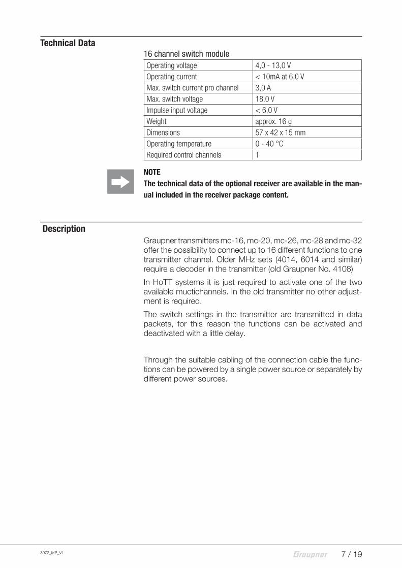
Technical Data16 channel switch moduleOperating voltage 4,0 - 13,0 VOperating current < 10mA at 6,0 VMax. switch current pro channel 3,0 AMax. switch voltage 18.0 VImpulse input voltage < 6,0 VWeight approx. 16 gDimensions 57 x 42 x 15 mmOperating temperature 0 - 40 °CRequired control channels 1
NOTEThe technical data of the optional receiver are available in the man-ual included in the receiver package content.
DescriptionGraupner transmitters mc-16, mc-20, mc-26, mc-28 and mc-32 offer the possibility to connect up to 16 different functions to one transmitter channel. Older MHz sets (4014, 6014 and similar) require a decoder in the transmitter (old Graupner No. 4108)
In HoTT systems it is just required to activate one of the two available muctichannels. In the old transmitter no other adjust-ment is required.
The switch settings in the transmitter are transmitted in data packets, for this reason the functions can be activated and deactivated with a little delay.
Through the suitable cabling of the connection cable the func-tions can be powered by a single power source or separately by different power sources.
8 / 19
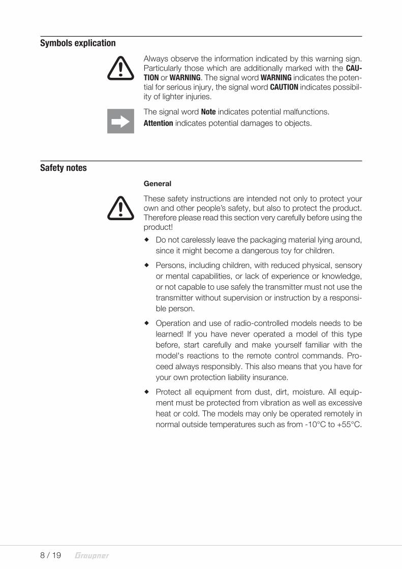
Symbols explication
! Always observe the information indicated by this warning sign.
Particularly those which are additionally marked with the CAU-TION or WARNING. The signal word WARNING indicates the poten-tial for serious injury, the signal word CAUTION indicates possibil-ity of lighter injuries.
The signal word Note indicates potential malfunctions.Attention indicates potential damages to objects.
Safety notes
General
! These safety instructions are intended not only to protect your
own and other people’s safety, but also to protect the product. Therefore please read this section very carefully before using the product!
� Do not carelessly leave the packaging material lying around, since it might become a dangerous toy for children.
� Persons, including children, with reduced physical, sensory or mental capabilities, or lack of experience or knowledge, or not capable to use safely the transmitter must not use the transmitter without supervision or instruction by a responsi-ble person.
� Operation and use of radio-controlled models needs to be learned! If you have never operated a model of this type before, start carefully and make yourself familiar with the model's reactions to the remote control commands. Pro-ceed always responsibly. This also means that you have for your own protection liability insurance.
� Protect all equipment from dust, dirt, moisture. All equip-ment must be protected from vibration as well as excessive heat or cold. The models may only be operated remotely in normal outside temperatures such as from -10°C to +55°C.

9 / 193972_MP_V1
The 16 channel switch module has been developed for use in RC models and it should only be used for the previewed scope.
Please note that the module should only be used within the indi-cated limit values (see technical data).
Use and store the unit in a dry environment only.
Every mechanical or electric modification of the module or the trespassing of the indicated limit values brings immediately to loss of all dispute rights against the producer, including the war-ranty service.
Any damage on the warranty seal on the back part of the mod-ule also brings to an immediate loss of warranty.
Always proof the correct functions of the module before every use.
Installing the ModuleThe best solution is to fix the module through some double-sided adhesive tape or hook and loop tape in the model. Alternatively you can also screw the plate with the included spacers, through the four fix holes. While tightening the screws pay attention that the plate should not be bent and that the lower part of the plate does not touch any other construction component (short-circuit risk).
For the holes dimensions please refer to the following illustration.
According to the used screw type, the screws can touch the ground (GND) of the plate and establish an unwanted connec-tion. In case of installation in a conducting surface, please pay particularly attention because of the risk of short-circuits.

10 / 19 3972_MP_V1
Setting the electric connections
The module consumes so few current that you can connect it through the included patch cable directly to the multichannel output of the receiver.
You can connect functions with low power consumption directly to the switch channel of the module, but only if the total power consumption of all the connected functions is lower than 1,0 A and only if the receiver voltage is enough (see switch plan).
To allow an as universal as possible use of the module, the mod-ule switches the ground (GND). This has the positive aspect that if necessary each function can be powered by a different source.
To allow this it is important that the minus pole of each power source, e.g. batteries, is connected to the other ones.
The functions will then be connected securely with the plus pole to the related battery and the minus pole of the function will be connected to the switch module.
In case of low currents the ground connection through the patch cable of the receiver is enough, on the other hand if the current is higher you should connect each ground separately (see switch plan).
Please note that inductive or capacitive functions ( as relais, motors or capacitors, etc...) during the switch-on phase can require much higher current than the one needed during the nor-mal use. A trespassing of the limit values can damage the mod-ule.

11 / 193972_MP_V1
In case of currents higher than 1,0 A connect, as represented, an accessory ground (GND) line to the related pin A of the channel (as shown in the illustration). So you can avoid an overcharging of the connection rails of the module.
Patch cable
16 channel Switch module
Connection of a small function to channel 6B
Connection of a big function to channel 4
Patch cable
Receiver
16 channel Switch module
V+
V+
+
+
V-/GND
X1 - 4C
X1 - 4A
X2 - 6B
X2 - 6C
X2 - C9
X2 - B9
X2 - A9
X2 - C9
X2 - B9
X2 - A9
V-/GND
+ 4...18 Vmax. 3,0 A
Receiver
12 / 19 3972_MP_V1
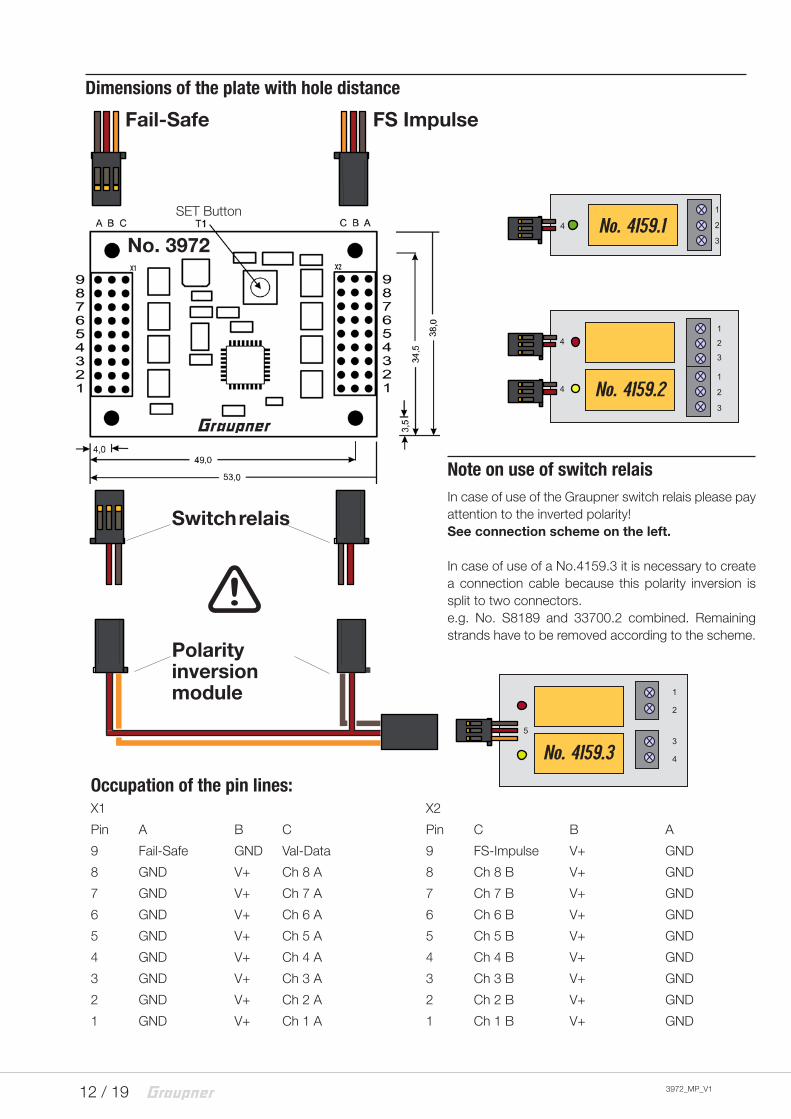
Dimensions of the plate with hole distance
No. 3972
Occupation of the pin lines:X1 X2
Pin A B C Pin C B A
9 Fail-Safe GND Val-Data 9 FS-Impulse V+ GND
8 GND V+ Ch 8 A 8 Ch 8 B V+ GND
7 GND V+ Ch 7 A 7 Ch 7 B V+ GND
6 GND V+ Ch 6 A 6 Ch 6 B V+ GND
5 GND V+ Ch 5 A 5 Ch 5 B V+ GND
4 GND V+ Ch 4 A 4 Ch 4 B V+ GND
3 GND V+ Ch 3 A 3 Ch 3 B V+ GND
2 GND V+ Ch 2 A 2 Ch 2 B V+ GND
1 GND V+ Ch 1 A 1 Ch 1 B V+ GND
1
2
3
4
4
1
2
3
1
2
3
4
5
1
2
3
4
No. 4159.1
No. 4159.2
No. 4159.3
Note on use of switch relaisIn case of use of the Graupner switch relais please pay attention to the inverted polarity! See connection scheme on the left.
In case of use of a No.4159.3 it is necessary to create a connection cable because this polarity inversion is split to two connectors. e.g. No. S8189 and 33700.2 combined. Remaining strands have to be removed according to the scheme.
Fail-Safe FS Impulse
SET Button
!
Switch relais
Polarity inversion module

13 / 193972_MP_V1
Programming the switch assignment of HoTT transmitter
To allow the transmitter to transmit the data correctly, you still have to set one option in your transmitter.Enter the "Telemetry" menu, open the "Settings & view" line and move through the touch pads to the "CH OUT TYPE" line. Here please select the "SAME" mode!
This mode is absolutely necessary for the use of the multiswitch-module!!
After having installed and connected all the required switches, now you have to assign the switches and to program correctly the multichannel functions.
Search in the menu the voice "Multichannel".
Touch shortly the "Set" button to open the selection menu.
Here you have two multichannels available, select one channel. Move to the desired channel and select it through the "Set" but-ton. So you can activate (ACT) or deactivate (INH) the channel.

14 / 19 3972_MP_V1
Programming the switch assignment of HoTT transmitter
Here activate both multichannels as multichannel, while the sec-ond multichannel has been assigned to the channel 6, with which we will proceed in the description.
Now move the cursor to the right field, select the "MULTICH 8CH" and confirm it through the "SET" button.
Then you are in this menu. Move the cursor to the red marked area and push the "SET" button.

15 / 193972_MP_V1
Soon after you will have to actuate the desired switch.
Programming the switch assignment of HoTT transmitter
After the actuation it looks like this, even if here you can see soon the switch number.
Please use the same process to assign the other switches in the transmitter.
Please note that always only one of the two switch setting pro input can be transmitted! In case of actuation of more than one switch it can bring to a function error.For this reason the switches with 3 functions / switch positions have to be connected always to a channel! The "Offset" should not be changed, e.g. bring it to "0", so as the travel should be to 100%!
If you open the "SERVO VIEW" menu, the related active multi-channels flicker to give a notice of this optional setting - it is totally normal.
For information about other parameters of the transmitter refer to the manual of your transmitter.
!
!
!
16 / 19 3972_MP_V1
Programming the switch assignment of Graupner/JR transmitter
Older MHz transmitters (4014, 6014 etc.) require the control or decoder module (old Graupner No. 4108). A switch assigna-tion, as required for the HoTT transmitters, is here not neces-sary. Accurate notes for the function are indicated in the respective transmitter manual.
Memory function
In the transmitter are included up to 8 switches, accordingly you can activate only 8 functions at the same time. Through the memory function you can also change it. Therefore one switch channel is brought in the memory func-tion, which by each switching activates or deactivates the chan-nel. You can bring every single channel individually in the mem-ory function. If you have brought at least 8 channels in this function, you will be able to activate and deactivate also 16 functions.
Switching on the memory function
Switch as usual the model and the transmitter on, move all the switches on the transmitter to the middle or Off position and pro-ceed as follows:
• Push and hold the T1 button on the plate• Activate (ON) the switch that you want to bring in the mem-ory function• Release the T1 button
That was all. Of course you can bring also several switches in the memory function.

17 / 193972_MP_V1
Memory function deactivation
You can also deactivate the memory function in the same way as you have activated it.Switch as usual the model and the transmitter on and proceed as follows:
• Activate (ON) the switch that you want to remove from the memory function• Push and hold the T1 SET button on the plate
• Deactivate (OFF) the switch in the transmitter.• Release then the T1 SET button
That was all. Of course you can remove also several switches from the memory function.
The only one difference between activating and deactivating the memory function is the position of the switch in the transmitter in the moment in which you push the T1 button on the plate and which position has the switch after the release of the T1 SET button.From OFF to ON activates the memory function, from ON to OFF deactivates the memory function.
Fail-Safe function
In case of malfunction of the receiver or in case of loss of the receiver impulse you can program the multiswitch module so that all the switch channels are automatically deactivated.Therefore connect the X1-9A with X1-9B and set also your transmitter or receiver in this mode. Only with active Fail-Safe function the module can deactivate the functions.The mode for the Fail-Safe function is requested when the mod-ule is switched on, changes during the use of the module are not saved. !

18 / 19 3972_MP_V1
Validating the transmission
The switch settings are serially requested in the transmitter and transmitted. First when from the switch module has been rec-ognized the complete data packet, the outputs switch accord-ing to the switch settings of the transmitter.Nevertheless interference impulses can lead to error switch pro-cesses.To make the switch processes even safer, there is the possibility in the 16 channel switch module, to compare the related switch settings from two sequential data packets. Only if the switch set-tings from two different but consequential data packets match the channel will be activated.Through this validation you can have an almost 100% safe switch of the channel but it will also be slower.You can activate this function by connecting the X1-9B with X1-9C.You can activate this function in parallel with the Fail-Safe func-tion, all you have to do is to connect all the X1-9 pins to each other.
Firmware update
The 16 channel switch module has been specifically been devel-oped for Graupner HoTT 2,4 GHz transmission systems and needs no other settings. If you have any question or problem during the use, please contact us under Hotline [email protected] or +49 (7021) 722-130.

19 / 193972_MP_V1
Notes on environmental protection
Disposal notesThis symbol on the product, user manual or packaging indicates that this product must not be disposed of with other household waste at the end of its life. It must be handed over to the appli-cable collection point for the recycling of electrical and electronic equipment.
The materials are recyclable as marked. By recycling, material reusing or other forms of scrap usage you are making an import-ant contribution to environmental protection.
Batteries and accumulators must be removed from the device and disposed of at an appropriate collection point. Please inquire if necessary from the local authority for the appropriate disposal site.
Care and maintenance
Notes on careThe product does not need any maintenance, it works so as it is without any special care. In your own interests protect it from dust, dirt and moisture.
WarrantyThe Graupner, Henriettenstrassee 96, 73230 Kirchheim/Teck grants from the date of purchase of this product for a period of 24 months. The warranty applies only to the material or opera-tional defects already existing when you purchased the item. Damage due to misuse, wear, overloading, incorrect accesso-ries or improper handling are excluded from the guarantee. The legal rights and claims are not affected by this guarantee. Please check exactly defects before a claim or send the product, because we have to ask you to pay shipping costs if the item is free from defects.
The present construction or user manual is for informational pur-poses only and may be changed without prior notice. The cur-rent version can be found on the Internet at www.graupner.de on the relevant product page. In addition, the company Graupner has no responsibility or liability for any errors or inaccuracies that may appear in construction or operation manuals.
No liability can be accepted for printing errors.
P


![CHRISTOPH GRAUPNER (1683–1760) · GRAUPNER: ORCHESTRAL SUITES FINNISH BAROQUE ORCHESTRA · KAAKINEN-PILCH ONDINE ODE 1220-2 ONDINE ODE 1220-2 [76’29] · English notes enclosed](https://img.dokumen.tips/doc/110x75/607c299345e9d35042300c02/christoph-graupner-1683a1760-graupner-orchestral-suites-finnish-baroque-orchestra.jpg)