Embed Size (px)
Citation preview

ADS8365
®
1FEATURESDESCRIPTION
APPLICATIONS
Interface
Conversion
and
Control
and
FIFO
Register
6x
EOC
FD
CS
WR
RD
Data
Input/Output
16
RESET
BYTE
CLK
CH A0-
CH A0+
CH A1-
CH A1+
SAR
CDAC
S/H
AmpComp
CDAC
Comp
CH B0-
CH B0+
HOLDA
CH B1-
CH B1+
SAR
CDAC
Comp
CDAC
Comp
CH C0-
CH C0+
CH C1-
CH C1+
REFIN
REFOUT
SAR
CDAC
Comp
CDAC
Comp
HOLDB
HOLDC
ADD
A2
A1
A0
Internal
2.5V
Reference
S/H
Amp
S/H
Amp
S/H
Amp
S/H
Amp
S/H
Amp
NAP
ADS8365
www.ti.com .................................................................................................................................................... SBAS362C–AUGUST 2006–REVISED MARCH 2008
16-Bit, 250kSPS, 6-Channel, Simultaneous SamplingSAR ANALOG-TO-DIGITAL CONVERTERS
2• Six Input Channels• Fully Differential Inputs The ADS8365 includes six, 16-bit, 250kSPS
analog-to-digital converters (ADCs) with six fully• Six Independent 16-Bit ADCsdifferential input channels grouped into three pairs for
• 4µs Total Throughput per Channel high-speed simultaneous signal acquisition. Inputs to• Low Power: the sample-and-hold amplifiers are fully differential
200mW in Normal Mode and are maintained differential to the input of theADC. This architecture provides excellent5mW in Nap Modecommon-mode rejection of 80dB at 50kHz, which is50µW in Power-Down Modeimportant in high-noise environments.• TQFP-64 Package PackageThe ADS8365 offers a flexible, high-speed parallelinterface with a direct address mode, a cycle, and aFIFO mode. The output data for each channel is• Motor Controlavailable as a 16-bit word.• Multi-Axis Positioning Systems
• 3-Phase Power Control
1
Please be aware that an important notice concerning availability, standard warranty, and use in critical applications ofTexas Instruments semiconductor products and disclaimers thereto appears at the end of this data sheet.
2All trademarks are the property of their respective owners.
PRODUCTION DATA information is current as of publication date. Copyright © 2006–2008, Texas Instruments IncorporatedProducts conform to specifications per the terms of the TexasInstruments standard warranty. Production processing does notnecessarily include testing of all parameters.

ABSOLUTE MAXIMUM RATINGS (1)
DISSIPATION RATINGS
ADS8365
SBAS362C–AUGUST 2006–REVISED MARCH 2008.................................................................................................................................................... www.ti.com
This integrated circuit can be damaged by ESD. Texas Instruments recommends that all integrated circuits be handled withappropriate precautions. Failure to observe proper handling and installation procedures can cause damage.
ESD damage can range from subtle performance degradation to complete device failure. Precision integrated circuits may be moresusceptible to damage because very small parametric changes could cause the device not to meet its published specifications.
ORDERING INFORMATION (1)
MAXIMUM NOINTEGRAL MISSINGLINEARITY CODES SPECIFIED TRANSPORT
ERROR ERROR PACKAGE- PACKAGE TEMPERATURE PACKAGE ORDERING MEDIA,PRODUCT (LSB) (LSB) LEAD DESIGNATOR RANGE MARKING NUMBER QUANTITY
ADS8365IPAG Tray, 160ADS8365 ±4 14 TQFP-64 PAG –40°C to +85°C ADS8365AI Tape andADS8365IPAGR Reel, 1500
(1) For the most current package and ordering information, see the Package Option Addendum located at the end of this data sheet, or seethe TI website at www.ti.com.
over operating free-air temperature range (unless otherwise noted)
ADS8365 UNITSupply voltage, AGND to AVDD –0.3 to 6 VSupply voltage, BGND to BVDD –0.3 to 6 VAnalog input voltage range AGND – 0.3 to AVDD + 0.3 VReference input voltage range AGND – 0.3 to AVDD + 0.3 VDigital input voltage range BGND – 0.3 to BVDD + 0.3 VGround voltage differences, AGND to BGND ±0.3 VVoltage differences, BVDD to AGND –0.3 to 6 VInput current to any pin except supply –20 to 20 mAPower dissipation See Dissipation Ratings TableOperating virtual junction temperature range, TJ –40 to +150 °COperating free-air temperature range, TA –40 to +85 °CStorage temperature range, TSTG –65 to +150 °C
(1) Stresses beyond those listed under Absolute Maximum Ratings may cause permanent damage to the device. These are stress ratingsonly, and functional operation of the device at these or any other conditions beyond those indicated under Recommended OperatingConditions is not implied. Exposure to absolute-maximum rated conditions for extended periods may affect device reliability.
DERATINGFACTOR ABOVE TA ≤ +25°C TA = +70°C TA = +85°C
BOARD PACKAGE RθJC RθJA TA = +25°C POWER RATING POWER RATING POWER RATINGLow-K (1) PAG 8.6°C/W 68.5°C/W 14.598mW/°C 1824mW 1168mW 949mWHigh-K (2) PAG 8.6°C/W 42.8°C/W 23.364mW/°C 2920mW 1869mW 1519mW
(1) The JEDEC Low K (1s) board design used to derive this data was a 3-inch x 3-inch, two-layer board with 2-ounce copper traces on topof the board.
(2) The JEDEC High K (2s2p) board design used to derive this data was a 3-inch x 3-inch, multilayer board with 1-ounce internal power andground planes, and 2-ounce copper traces on the top and bottom of the board.
2 Submit Documentation Feedback Copyright © 2006–2008, Texas Instruments Incorporated
Product Folder Link(s): ADS8365

RECOMMENDED OPERATING CONDITIONS
ELECTRICAL CHARACTERISTICS: 100kSPS
ADS8365
www.ti.com .................................................................................................................................................... SBAS362C–AUGUST 2006–REVISED MARCH 2008
MIN NOM MAX UNITSupply voltage, AVDD to AGND 4.75 5 5.25 V
Low-voltage levels 2.7 3.6 VSupply voltage, BVDD to BGND
5V logic levels 4.5 5 5.5 VReference input voltage 1.5 2.5 2.6 VOperating common-mode signal, –IN 2.2 2.5 2.8 VAnalog inputs, +IN – (–IN) 0 ±VREF VOperating junction temperature range, TJ –40 +125 °C
Over recommended operating free-air temperature range at –40°C to +85°C, AVDD = 5V, BVDD = 3V, VREF = internal +2.5V, fCLK = 2MHz, andfSAMPLE = 100kSPS, unless otherwise noted.
ADS8365
PARAMETER TEST CONDITIONS MIN TYP (1) MAX UNIT
ANALOG INPUT
Full-scale range FSR +IN – (–IN) ±VREF V
Operating common-mode signal 2.2 2.8 V
Input resistance –IN = VREF 750 Ω
Input capacitance –IN = VREF 25 pF
Input leakage current –IN = VREF ±1 nA
Differential input resistance –IN = VREF 1500 Ω
Differential input capacitance –IN = VREF 15 pF
At dc 84 dBCommon-mode rejection ratio CMRR
VIN = ±1.25VPP at 50kHz 80 dB
Bandwidth BW FS sinewave, –3dB 10 MHz
DC ACCURACY
Resolution 16 Bits
No missing codes NMC 14 Bits
Integral linearity error INL ±1.5 ±4 LSB
Differential nonlinearity DNL ±1.5 LSB
Bipolar offset error VOS ±1 ±2.3 mV
Bipolar offset error match Only pair-wise matching 0.2 1 mV
Bipolar offset error drift TCVOS 0.8 ppm/°C
Gain error GERR Referenced to VREF ±0.05 ±0.25 %FSR
Gain error match Only pair-wise matching 0.005 0.05 %FSR
Gain error drift TCGERR 2 ppm/°C
Noise 60 µVrms
Power-supply rejection ratio PSRR 4.75V < AVDD < 5.25V –87 dB
SAMPLING DYNAMICS
Conversion time per ADC tCONV 50kHz ≤ fCLK ≤ 5MHz 3.2 320 µs
Acquisition time tAQ fCLK = 5MHz 800 ns
Aperture delay 5 ns
Aperture delay matching 100 ps
Aperture jitter 50 ps
Clock frequency 0.05 5 MHz
(1) All typical values are at +25°C.
Copyright © 2006–2008, Texas Instruments Incorporated Submit Documentation Feedback 3
Product Folder Link(s): ADS8365

ADS8365
SBAS362C–AUGUST 2006–REVISED MARCH 2008.................................................................................................................................................... www.ti.com
ELECTRICAL CHARACTERISTICS: 100kSPS (continued)Over recommended operating free-air temperature range at –40°C to +85°C, AVDD = 5V, BVDD = 3V, VREF = internal +2.5V, fCLK = 2MHz, andfSAMPLE = 100kSPS, unless otherwise noted.
ADS8365
PARAMETER TEST CONDITIONS MIN TYP (1) MAX UNIT
AC ACCURACY
Total harmonic distortion THD VIN = ±2.5VPP at 50kHz –94 dB
Spurious-free dynamic range SFDR VIN = ±2.5VPP at 50kHz 95 dB
Signal-to-noise ratio SNR VIN = ±2.5VPP at 10kHz 88 dB
Signal-to-noise + distortion SINAD VIN = ±2.5VPP at 10kHz 87 dB
Channel-to-channel isolation 95 dB
Effective number of bits ENOB 14.3 Bits
VOLTAGE REFERENCE OUTPUT
Reference voltage output VOUT 2.475 2.5 2.525 V
Initial accuracy ±1 %
Output voltage temperature drift dVOUT/dT ±20 ppm/°C
f = 0.1Hz to 10Hz, CL = 10µF 40 µVPPOutput voltage noise
f = 10Hz to 10kHz, CL = 10µF 8 µVrms
Power-supply rejection ratio PSRR 60 dB
Output impedance ROUT 2 kΩ
Short-circuit current ISC 1.25 mA
Turn-on settling time to 0.1% at CL = 0pF 100 µs
VOLTAGE REFERENCE INPUT
Reference voltage input VIN 1.5 2.5 2.6 V
Reference input resistance 100 MΩ
Reference input capacitance 5 pF
Reference input current 1 µA
DIGITAL INPUTS (2)
Logic family CMOS
High-level input voltage VIH 0.7 × BVDD BVDD + 0.3 V
Low-level input voltage VIL –0.3 0.3 × BVDD V
Input current IIN VI = BVDD or GND ±50 nA
Input capacitance CI 5 pF
DIGITAL OUTPUTS (2)
Logic family CMOS
High-level output voltage VOH BVDD = 4.5V, IOH = –100µA 4.44 V
Low-level output voltage VOL BVDD = 4.5V, IOL = 100µA 0.5 V
High-impedance state output current IOZ CS = BVDD, VI = BVDD or GND ±50 nA
Output capacitance CO 5 pF
Load capacitance CL 30 pF
DIGITAL INPUTS (3)
Logic family LVCMOS
High-level input voltage VIH BVDD = 3.6V 2 BVDD + 0.3 V
Low-level input voltage VIL BVDD = 2.7V –0.3 0.8 V
Input current IIN VI = BVDD or GND ±50 nA
Input capacitance CI 5 pF
(2) Applies for 5.0V nominal supply: BVDD (min) = 4.5V and BVDD (max) = 5.5V.(3) Applies for 3.0V nominal supply: BVDD (min) = 2.7V and BVDD (max) = 3.6V.
4 Submit Documentation Feedback Copyright © 2006–2008, Texas Instruments Incorporated
Product Folder Link(s): ADS8365

ADS8365
www.ti.com .................................................................................................................................................... SBAS362C–AUGUST 2006–REVISED MARCH 2008
ELECTRICAL CHARACTERISTICS: 100kSPS (continued)Over recommended operating free-air temperature range at –40°C to +85°C, AVDD = 5V, BVDD = 3V, VREF = internal +2.5V, fCLK = 2MHz, andfSAMPLE = 100kSPS, unless otherwise noted.
ADS8365
PARAMETER TEST CONDITIONS MIN TYP (1) MAX UNIT
DIGITAL OUTPUTS (4)
Logic family LVCMOS
High-level output voltage VOH BVDD = 2.7V, IOH = –100µA BVDD – 0.2 V
Low-level output voltage VOL BVDD = 2.7V, IOL = 100µA 0.2 V
High-impedance state output current IOZ CS = BVDD, VI = BVDD or GND ±50 nA
Output capacitance CO 5 pF
Load capacitance CL 30 pF
DATA FORMAT
Bit DB4 = 1 Binary two's complementData format
Bit DB4 = 0 Straight binary coding
POWER SUPPLY
Analog supply voltage AVDD 4.75 5.25 V
Low-voltage levels 2.7 3.6 VBuffer I/O supply voltage BVDD
5V logic levels 4.5 5.5 V
Analog operating supply current AIDD 38 45 mA
BVDD = 3V 60 90 µABuffer I/O operating supply current BIDD
BVDD = 5V 100 150 µA
BVDD = 3V 190 225 mW
BVDD = 5V 190 225 mWPower dissipation
Nap mode enabled 5 mW
Powerdown enabled 50 µW
(4) Applies for 3.0V nominal supply: BVDD (min) = 2.7V and BVDD (max) = 3.6V.
Copyright © 2006–2008, Texas Instruments Incorporated Submit Documentation Feedback 5
Product Folder Link(s): ADS8365

ELECTRICAL CHARACTERISTICS: 250kSPS
ADS8365
SBAS362C–AUGUST 2006–REVISED MARCH 2008.................................................................................................................................................... www.ti.com
Over recommended operating free-air temperature range at –40°C to +85°C, AVDD = 5V, BVDD = 3V, VREF = internal +2.5V, fCLK = 5MHz, andfSAMPLE = 250kSPS, unless otherwise noted
ADS8365
PARAMETER TEST CONDITIONS MIN TYP (1) MAX UNIT
ANALOG INPUT
Full-scale range FSR +IN – (–IN) ±VREF V
Operating common-mode signal 2.2 2.8 V
Input resistance –IN = VREF 750 Ω
Input capacitance –IN = VREF 25 pF
Input leakage current –IN = VREF ±1 nA
Differential input resistance –IN = VREF 1500 Ω
Differential input capacitance –IN = VREF 15 pF
At dc 84 dBCommon-mode rejection ratio CMRR
VIN = ±1.25VPP at 50kHz 80 dB
Bandwidth BW FS sinewave, –3dB 10 MHz
DC ACCURACY
Resolution 16 Bits
No missing codes NMC 14 Bits
Integral linearity error INL ±3 ±8 LSB
Differential nonlinearity DNL Specified for 14 bit ±1.5 LSB
Bipolar offset error VOS ±1 ±2.3 mV
Bipolar offset error match Only pair-wise matching 0.2 1 mV
Bipolar offset error drift TCVOS 0.8 ppm/°C
Gain error GERR Referenced to VREF ±0.05 ±0.25 %FSR
Gain error match Only pair-wise matching 0.005 0.05 %FSR
Gain error drift TCGERR 2 ppm/°C
Noise 60 µVrms
Power-supply rejection ratio PSRR 4.75V < AVDD < 5.25V –87 dB
SAMPLING DYNAMICS
Conversion time per ADC tCONV 50kHz ≤ fCLK ≤ 5MHz 3.2 320 µs
Acquisition time tAQ fCLK = 5MHz 800 ns
Throughput rate 250 kSPS
Aperture delay 5 ns
Aperture delay matching 100 ps
Aperture jitter 50 ps
Clock frequency 0.05 5 MHz
AC ACCURACY
Total harmonic distortion THD VIN = ±2.5VPP at 50kHz –94 dB
Spurious-free dynamic range SFDR VIN = ±2.5VPP at 50kHz 95 dB
Signal-to-noise ratio SNR VIN = ±2.5VPP at 10kHz 88 dB
Signal-to-noise + distortion SINAD VIN = ±2.5VPP at 10kHz 87 dB
Channel-to-channel isolation 95 dB
Effective number of bits ENOB 14.3 Bits
(1) All typical values are at +25°C.
6 Submit Documentation Feedback Copyright © 2006–2008, Texas Instruments Incorporated
Product Folder Link(s): ADS8365

ADS8365
www.ti.com .................................................................................................................................................... SBAS362C–AUGUST 2006–REVISED MARCH 2008
ELECTRICAL CHARACTERISTICS: 250kSPS (continued)Over recommended operating free-air temperature range at –40°C to +85°C, AVDD = 5V, BVDD = 3V, VREF = internal +2.5V, fCLK = 5MHz, andfSAMPLE = 250kSPS, unless otherwise noted
ADS8365
PARAMETER TEST CONDITIONS MIN TYP (1) MAX UNIT
VOLTAGE REFERENCE OUTPUT
Reference voltage output VOUT 2.475 2.5 2.525 V
Initial accuracy ±1 %
Output voltage temperature drift dVOUT/dT ±20 ppm/°C
f = 0.1Hz to 10Hz, CL = 10µF 40 µVPPOutput voltage noise
f = 10Hz to 10kHz, CL = 10µF 8 µVrms
Power-supply rejection ratio PSRR 60 dB
Output impedance ROUT 2 kΩ
Short-circuit current ISC 1.25 mA
Turn-on settling time to 0.1% at CL = 0pF 100 µs
VOLTAGE REFERENCE INPUT
Reference voltage input VIN 1.5 2.5 2.6 V
Reference input resistance 100 MΩ
Reference input capacitance 5 pF
Reference input current 1 µA
DIGITAL INPUTS (2)
Logic family CMOS
High-level input voltage VIH 0.7 × BVDD BVDD + 0.3 V
Low-level input voltage VIL –0.3 0.3 × BVDD V
Input current IIN VI = BVDD or GND ±50 nA
Input capacitance CI 5 pF
DIGITAL OUTPUTS (2)
Logic family CMOS
High-level output voltage VOH BVDD = 4.5V, IOH = –100µA 4.44 V
Low-level output voltage VOL BVDD = 4.5V, IOL = 100µA 0.5 V
High-impedance state output current IOZ CS = BVDD, VI = BVDD or GND ±50 nA
Output capacitance CO 5 pF
Load capacitance CL 30 pF
DIGITAL INPUTS (3)
Logic family LVCMOS
High-level input voltage VIH BVDD = 3.6V 2 BVDD + 0.3 V
Low-level input voltage VIL BVDD = 2.7V –0.3 0.8 V
Input current IIN VI = BVDD or GND ±50 nA
Input capacitance CI 5 pF
DIGITAL OUTPUTS (3)
Logic family LVCMOS
High-level output voltage VOH BVDD = 2.7V, IOH = –100µA BVDD – 0.2 V
Low-level output voltage VOL BVDD = 2.7V, IOL = 100µA 0.2 V
High-impedance state output current IOZ CS = BVDD, VI = BVDD or GND ±50 nA
Output capacitance CO 5 pF
Load capacitance CL 30 pF
(2) Applies for 5.0V nominal supply: BVDD (min) = 4.5V and BVDD (max) = 5.5V.(3) Applies for 3.0V nominal supply: BVDD (min) = 2.7V and BVDD (max) = 3.6V.
Copyright © 2006–2008, Texas Instruments Incorporated Submit Documentation Feedback 7
Product Folder Link(s): ADS8365

EQUIVALENT INPUT CIRCUIT
R
750W
ON
BVDD
DIN
BGND
AVDD
AIN
AGND
Diode Turn-on Voltage: 0.35V
Equivalent Digital Input CircuitEquivalent Analog Input Circuit
C
20pF(SAMPLE)
ADS8365
SBAS362C–AUGUST 2006–REVISED MARCH 2008.................................................................................................................................................... www.ti.com
ELECTRICAL CHARACTERISTICS: 250kSPS (continued)Over recommended operating free-air temperature range at –40°C to +85°C, AVDD = 5V, BVDD = 3V, VREF = internal +2.5V, fCLK = 5MHz, andfSAMPLE = 250kSPS, unless otherwise noted
ADS8365
PARAMETER TEST CONDITIONS MIN TYP (1) MAX UNIT
DATA FORMAT
Bit DB4 = 1 Binary two's complementData format
Bit DB4 = 0 Straight binary coding
POWER SUPPLY
Analog supply voltage AVDD 4.75 5.25 V
Low-voltage levels 2.7 3.6 VBuffer I/O supply voltage BVDD
5V logic levels 4.5 5.5 V
Analog operating supply current AIDD 40 48 mA
BVDD = 3V 150 225 µABuffer I/O operating supply current BIDD
BVDD = 5V 250 375 µA
BVDD = 3V 200 240 mW
BVDD = 5V 201 241 mWPower dissipation
Nap mode enabled 5 mW
Powerdown enabled 50 µW
8 Submit Documentation Feedback Copyright © 2006–2008, Texas Instruments Incorporated
Product Folder Link(s): ADS8365
PIN CONFIGURATION
48
47
46
45
44
43
42
41
40
39
38
37
36
35
34
33
D0
D1
D2
D3
D4
D5
D6
D7
D8
D9
D10
D11
D12
D13
D14
D15
1
2
3
4
5
6
7
8
9
10
11
12
13
14
15
16
CH A1-
CH A1+
AVDD
AGND
SGND
CH B0+
CH B0-
AVDD
AGND
SGND
CH B1-
CH B1+
AVDD
AGND
SGND
CH C0+
CH
C0
-
CH
C1
-
CH
C1+
NA
P
AG
ND
AV
DD
BY
TE
BV
DD
BG
ND
FD
EO
C
CLK
RD
WR
CS
BG
ND
64 63 62 61 60 59 58 57 56 55 54
17 18 19 20 21 22 23 24 25 26 27
53 52 51 50 49
28 29 30 31 32
ADS8365
CH
A0
CH
A0+
RE
F
RE
F
AG
ND
AV
HO
LD
C
HO
LD
B
HO
LD
A
A0
A1
A2
AD
D
RE
SE
T
BV
BG
ND
-
IN OU
T
DD
DD
ADS8365
www.ti.com .................................................................................................................................................... SBAS362C–AUGUST 2006–REVISED MARCH 2008
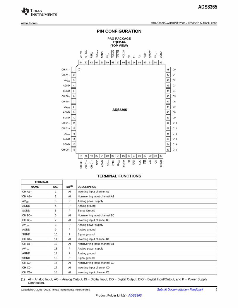
PAG PACKAGETQFP-64
(TOP VIEW)
TERMINAL FUNCTIONSTERMINAL
NAME NO. I/O (1) DESCRIPTION
CH A1– 1 AI Inverting input channel A1
CH A1+ 2 AI Noninverting input channel A1
AVDD 3 P Analog power supply
AGND 4 P Analog ground
SGND 5 P Signal Ground
CH B0+ 6 AI Noninverting input channel B0
CH B0– 7 AI Inverting input channel B0
AVDD 8 P Analog power supply
AGND 9 P Analog ground
SGND 10 P Signal ground
CH B1– 11 AI Inverting input channel B1
CH B1+ 12 AI Noninverting input channel B1
AVDD 13 P Analog power supply
AGND 14 P Analog ground
SGND 15 P Signal ground
CH C0+ 16 AI Noninverting input channel C0
CH C0– 17 AI Inverting input channel C0
CH C1– 18 AI Inverting input channel C1
(1) AI = Analog Input, AO = Analog Output, DI = Digital Input, DO = Digital Output, DIO = Digital Input/Output, and P = Power SupplyConnection.
Copyright © 2006–2008, Texas Instruments Incorporated Submit Documentation Feedback 9
Product Folder Link(s): ADS8365

ADS8365
SBAS362C–AUGUST 2006–REVISED MARCH 2008.................................................................................................................................................... www.ti.com
TERMINAL FUNCTIONS (continued)TERMINAL
NAME NO. I/O (1) DESCRIPTION
CH C1+ 19 AI Noninverting input channel C1
NAP 20 DI Nap mode.Low level or unconnected = normal operation; high level = Nap mode.
AGND 21 P Analog ground
AVDD 22 P +5V power supply
BYTE 23 DI 2 x 8 output capability (active high)
BVDD 24 P Power supply for digital interface from 3V to 5V
BGND 25 P Buffer digital ground
FD 26 DO First data (A0 data)
EOC 27 DO End of conversion (active low)
An external CMOS compatible clock can be applied to the CLK input to synchronize the conversion process to anCLK 28 DI external source.
RD 29 DI Read (active low)
WR 30 DI Write (active low)
CS 31 DI Chip select (active low)
BGND 32 P Buffer digital ground
D15 33 DO Data bit 15 (MSB)
D14 34 DO Data bit 14
D13 35 DO Data bit 13
D12 36 DO Data bit 12
D11 37 DO Data bit 11
D10 38 DO Data bit 10
D9 39 DO Data bit 9
D8 40 DO Data bit 8
D7 41 DIO Data bit 7 (software input 7)
D6 42 DIO Data bit 6 (software input 6)
D5 43 DIO Data bit 5 (software input 5)
D4 44 DIO Data bit 4 (software input 4)
D3 45 DIO Data bit 3 (software input 3)
D2 46 DIO Data bit 2 (software input 2)
D1 47 DIO Data bit 1 (software input 1)
D0 48 DIO Data bit 0 (software input 0) (LSB)
BGND 49 P Buffer digital ground
BVDD 50 P Power supply for digital interface from 3V to 5V
RESET 51 DI Global reset (active low)
ADD 52 DI Address mode select
A2 53 DI Address line 3
A1 54 DI Address line 2
A0 55 DI Address line 1
HOLDA 56 DI Hold command A (active low)
HOLDB 57 DI Hold command B (active low)
HOLDC 58 DI Hold command C (active low)
AVDD 59 P Analog power supply
AGND 60 P Analog ground
REFOUT 61 AO Reference output; attach 0.1µF and 10µF capacitors
REFIN 62 AI Reference input
CH A0+ 63 AI Noninverting input channel A0
CH A0– 64 AI Inverting input channel A0
10 Submit Documentation Feedback Copyright © 2006–2008, Texas Instruments Incorporated
Product Folder Link(s): ADS8365

TIMING INFORMATION
tW6
tD6
tD4 t
D5
tD7
tW5
tW1
tD1
tC1
tW3
CONVERSION
tCONV
ACQUISITION
tACQ
tW2
Bits 15 8– Bits 15 8–
CLK
HOLDX
EOC
CS
RD
D15–D8
D7–D0
BYTE
1 2 16 17 18 19 20 1 2
Bits 7 0–Bits 7 0–
tD10
CS
tD11
DB7:0
WR
WR or CS
tW6
ADS8365
www.ti.com .................................................................................................................................................... SBAS362C–AUGUST 2006–REVISED MARCH 2008
Figure 1. Read and Convert Timing
Figure 2. Write Timing
Copyright © 2006–2008, Texas Instruments Incorporated Submit Documentation Feedback 11
Product Folder Link(s): ADS8365

TIMING CHARACTERISTICS (1) (2) (3) (4)
ADS8365
SBAS362C–AUGUST 2006–REVISED MARCH 2008.................................................................................................................................................... www.ti.com
Over recommended operating free-air temperature range, TMIN to TMAX, AVDD = 5V, REFIN = REFOUT, VREF = internal +2.5V,fCLK = 5MHz, fSAMPLE = 250kSPS, and BVDD = 2.7 to 5V, unless otherwise noted,
SYMBOL DESCRIPTION MIN TYP MAX UNITtACQ Acquisition time 0.8 µstCONV Conversion time 3.2 µs
tC1 Cycle time of CLK 200 nstD1
(5) Delay time of rising edge of CLK after falling edge of HOLDX 10 nsBVDD = 5V 20 ns
tD2 Delay time of first hold after RESETBVDD = 3V 40 ns
tD4 Delay time of falling edge of RD after falling edge of CS 0 nstD5 Delay time of rising edge of CS after rising edge of RD 0 ns
BVDD = 5V 40 nstD6 Delay time of data valid after falling edge of RD
BVDD = 3V 60 nsBVDD = 5V 5 ns
tD7 Delay time of data hold from rising edge of RDBVDD = 3V 10 nsBVDD = 5V 50 ns
tD8 Delay time of RD high after CS lowBVDD = 3V 60 nsBVDD = 5V 10 ns
tD9 Delay time of RD low after address setupBVDD = 3V 20 nsBVDD = 5V 10 ns
tD10 Delay time of data valid to WR lowBVDD = 3V 20 nsBVDD = 5V 10 ns
tD11 Delay time of WR or CS high to data releaseBVDD = 3V 20 ns
tW1 Pulse width CLK high time or low time 60 nsBVDD = 5V 15 ns
tW2 Pulse width of HOLDX high time to be recognized againBVDD = 3V 30 nsBVDD = 5V 20 ns
tW3 Pulse width of HOLDX low timeBVDD = 3V 30 nsBVDD = 5V 20 ns
tW4 Pulse width of RESETBVDD = 3V 40 nsBVDD = 5V 30 ns
tW5 Pulse width of RD high timeBVDD = 3V 40 nsBVDD = 5V 50 ns
tW6 Pulse width of RD and CS both low timeBVDD = 3V 70 ns
(1) Assured by design.(2) All input signals are specified with rise time and fall time = 5ns (10% to 90% of BVDD ) and timed from a voltage level of (VIL + VIH )/2.(3) See Figure 1.(4) BYTE is asynchronous; when BYTE is 0, bits 15 to 0 appear at DB15 to DB0. When BYTE is 1, bits 15 to 8 appear on DB7 to DB0. RD
may remain LOW between changes in BYTE.(5) Only important when synchronization to clock is important.
12 Submit Documentation Feedback Copyright © 2006–2008, Texas Instruments Incorporated
Product Folder Link(s): ADS8365

TYPICAL CHARACTERISTICS
2.0
1.5
1.0
0.5
0
-0.5
-1.0
0 8192 16384 24576 32768 40960 49152 57344 65535
DN
L (
LS
B)
Code
4
3
2
1
0
1
2
3
4
0 8192 16384 24576 32768 40960 49152 57344 65535
INL (
LS
B)
Code
1.5
1.0
0.5
0
-0.5
-1.0
-1.5
-2.0
-2.5
-50 -25 100
Max
250 50 75
INL (
LS
B)
Temperature ( C)°
Min
1.5
1.0
0.5
0
-0.5
-1.0
-1.5
-2.0
-2.5
-50 -25 100
Max
250 50 75
INL (
LS
B)
Temperature ( C)°
Min
3.0
2.5
2.0
1.5
1.0
0.5
0
-0.5
-1.0
-1.5
-2.0
-50 -25 100250 50 75
DN
L (
LS
B)
Temperature (°C)
Min
Max
3.0
2.5
2.0
1.5
1.0
0.5
0
-0.5
-1.0
-1.5
-2.0
-50 -25 100250 50 75
DN
L (
LS
B)
Temperature ( C)°
Min
Max
ADS8365
www.ti.com .................................................................................................................................................... SBAS362C–AUGUST 2006–REVISED MARCH 2008
At TA = +25°C, AVDD = +5V, BVDD = +3V, VREF = internal +2.5V, fCLK = 5MHz, and fSAMPLE = 250kSPS, unless otherwise noted.
INTEGRAL LINEARITY ERROR DIFFERENTIAL LINEARITY ERRORvs CODE (100kSPS) vs CODE (100kSPS)
Figure 3. Figure 4.
MINIMUM AND MAXIMUM INL OF ALL CHANNELS MINIMUM AND MAXIMUM INL OF ALL CHANNELSvs TEMPERATURE (100kSPS) vs TEMPERATURE (250kSPS)
Figure 5. Figure 6.
MINIMUM AND MAXIMUM DNL OF ALL CHANNELS MINIMUM AND MAXIMUM DNL OF ALL CHANNELSvs TEMPERATURE (100kSPS) vs TEMPERATURE (250kSPS)
Figure 7. Figure 8.
Copyright © 2006–2008, Texas Instruments Incorporated Submit Documentation Feedback 13
Product Folder Link(s): ADS8365

0
-20
-40
-60
-80
-100
-120
-140
-160
0 25 1257550 100
Am
plit
ude (
dB
)
Frequency (kHz)
0
-20
-40
-60
-80
-100
-120
-140
-160
0 25 1257550 100
Am
plit
ude (
dB
)
Frequency (kHz)
100
95
90
85
80
75
70
1 10 100
SN
R a
nd S
INA
D (
dB
)
Frequency (kHz)
SINAD
SNR
120
115
110
105
100
95
90
85
80
1 10 100
SF
DR
and T
HD
(dB
)
Frequency (kHz)
SFDR
THD
90.0
89.5
89.0
88.5
88.0
87.5
87.0
86.5
86.0
85.5
85.0
-50 -25 100250 50 75
SIN
AD
and S
NR
(dB
)
Temperature ( C)°
SINAD
SNR
107
105
103
101
99
97
95
-50 -25 100250 50 75
SF
DR
and T
HD
(dB
)
Temperature ( C)°
SFDR
THD
ADS8365
SBAS362C–AUGUST 2006–REVISED MARCH 2008.................................................................................................................................................... www.ti.com
TYPICAL CHARACTERISTICS (continued)At TA = +25°C, AVDD = +5V, BVDD = +3V, VREF = internal +2.5V, fCLK = 5MHz, and fSAMPLE = 250kSPS, unless otherwise noted.
FREQUENCY SPECTRUM FREQUENCY SPECTRUM(16384 point FFT, fIN = 10kHz, –0.2dB) (16384 point FFT, fIN = 45kHz, –0.2dB)
Figure 9. Figure 10.
SIGNAL-TO-NOISE RATIO AND SPURIOUS-FREE DYNAMIC RANGE ANDSIGNAL-TO-NOISE + DISTORTION TOTAL HARMONIC DISTORTION
vs INPUT FREQUENCY (ALL CHANNELS) vs INPUT FREQUENCY (ALL CHANNELS)
Figure 11. Figure 12.
SIGNAL-TO-NOISE RATIO AND SPURIOUS-FREE DYNAMIC RANGE ANDSIGNAL-TO-NOISE + DISTORTION TOTAL HARMONIC DISTORTION
vs TEMPERATURE (ALL CHANNELS) vs TEMPERATURE (ALL CHANNELS)
Figure 13. Figure 14.
14 Submit Documentation Feedback Copyright © 2006–2008, Texas Instruments Incorporated
Product Folder Link(s): ADS8365

-0.8
-0.9
-1.0
-1.1
-1.2
-1.3
-1.4
-50 -25 100250 50 75
Offset (m
V)
Temperature ( C)°
A0
C0
B1
B0
C1A1
0.25
0.20
0.15
0.10
0.05
0
-0.05
-0.10
-0.15
-0.20
-0.25
-50 -25 100250 50 75
Offset M
atc
hin
g (
mV
)
Temperature (°C)
A
B
C
100
50
0
-50
-100
-150
-50 -25 100250 50 75
Gain
Err
or
(ppm
FS
R)
Temperature ( C)°
B1A0B0A1
C1
C0
100
50
0
-50
-100
-150
-50 -25 100250 50 75
Gain
Matc
h (
ppm
FS
R)
Temperature ( C)°
C
A
B
2.498
2.496
2.494
2.492
2.490
-50 -25 100250 50 75
V(V
)R
EF
OU
T
Temperature ( C)°
42
40
38
36
34
32
30
-50 -25 100250 50 75
IDD
A (
mA
)
Temperature (°C)
250kSPS
100kSPS
ADS8365
www.ti.com .................................................................................................................................................... SBAS362C–AUGUST 2006–REVISED MARCH 2008
TYPICAL CHARACTERISTICS (continued)At TA = +25°C, AVDD = +5V, BVDD = +3V, VREF = internal +2.5V, fCLK = 5MHz, and fSAMPLE = 250kSPS, unless otherwise noted.
OFFSET OF ALL CHANNELS OFFSET MATCHING OF CHANNEL PAIRSvs TEMPERATURE vs TEMPERATURE
Figure 15. Figure 16.
GAIN ERROR OF ALL CHANNELS GAIN-ERROR MATCHING OF CHANNEL PAIRSvs TEMPERATURE vs TEMPERATURE
Figure 17. Figure 18.
REFERENCE VOLTAGE OUTPUT ANALOG SUPPLY CURRENTvs TEMPERATURE vs TEMPERATURE
Figure 19. Figure 20.
Copyright © 2006–2008, Texas Instruments Incorporated Submit Documentation Feedback 15
Product Folder Link(s): ADS8365

INTRODUCTION
REFERENCE
ANALOG INPUT
SAMPLE AND HOLD
ADS8365
ADS8365
Single-Ended Input
Common
Voltage
-V to +VREF REF
peak-to-peak
Differential Input
Common
Voltage
VREF
peak-to-peak
VREF
peak-to-peak
ADS8365
SBAS362C–AUGUST 2006–REVISED MARCH 2008.................................................................................................................................................... www.ti.com
5ns. The average delta of repeated aperture delayThe ADS8365 is a high-speed, low-power, values (also known as aperture jitter) is typicallysix-channel simultaneous sampling and converting, 50ps. These specifications reflect the ability of the16-bit ADC that operates from a single +5V supply. ADS8365 to capture ac input signals accurately at theThe input channels are fully differential with a typical exact same moment in time.common-mode rejection of 80dB. The ADS8365contains six 4µs successive approximation ADCs, sixdifferential sample-and-hold amplifiers, an internal+2.5V reference with REFIN and REFOUT pins, and a Under normal operation, REFOUT (pin 61) can behigh-speed parallel interface. There are six analog directly connected to REFIN (pin 62) to provide aninputs that are grouped into three channel pairs (A, B, internal +2.5V reference to the ADS8365. Theand C). There are six ADCs, one for each input that ADS8365 can operate, however, with an externalcan be sampled and converted simultaneously, thus reference in the range of 1.5V to 2.6V, for apreserving the relative phase information of the corresponding full-scale range of 3.0V to 5.2V, assignals on both analog inputs. Each pair of channels long as the input does not exceed the AVDD + 0.3Vhas a hold signal (HOLDA, HOLDB, and HOLDC) to limit.allow simultaneous sampling on each channel pair,
The reference output of the ADS8365 has anon four or on all six channels. The part accepts aimpedance of 2kΩ. The high impedance referencedifferential analog input voltage in the range of –VREF input can be driven directly. For an external resistiveto +VREF, centered on the common-mode voltageload, an additional buffer is required. A load(see the Analog Input section). The ADS8365 alsocapacitance of 0.1µF to 10µF should be applied toaccepts bipolar input ranges when a level shift circuitthe reference output to minimize noise. If an externalis used at the front end (see Figure 26).reference is used, the three input buffers provide
A conversion is initiated on the ADS8365 by bringing isolation between the external reference and thethe HOLDX pin low for a minimum of 20ns. HOLDX CDACs. These buffers are also used to recharge alllow places the sample-and-hold amplifiers of the X the capacitors of all CDACs during conversion.channels in the hold state simultaneously and theconversion process is started on each channel. TheEOC output goes low for half a clock cycle when the
The analog input is bipolar and fully differential. Thereconversion is latched into the output register. Theare two general methods of driving the analog inputdata can be read from the parallel output busof the ADS8365: single-ended or differential, asfollowing the conversion by bringing both RD and CSshown in Figure 21 and Figure 22. When the input islow. Conversion time for the ADS8365 is 3.2µs whensingle-ended, the –IN input is held at thea 5MHz external clock is used. The correspondingcommon-mode voltage. The +IN input swings aroundacquisition time is 0.8µs. To achieve the maximumthe same common voltage and the peak-to-peakoutput data rate (250kSPS), the read function can beamplitude is the (common-mode + VREF) and theperformed during the next conversion. NOTE: This(common-mode –VREF). The value of VREF determinesmode of operation is described in more detail in thethe range over which the common-mode voltage mayTiming and Control section of this data sheet.vary (see Figure 23).
The sample-and-hold amplifiers on the ADS8365allow the ADCs to accurately convert an input sinewave of full-scale amplitude to 16-bit resolution. Theinput bandwidth of the sample-and-hold amplifiers isgreater than the Nyquist rate (Nyquist = 1/2 of thesampling rate) of the ADC, even when the ADC isoperated at its maximum throughput rate of 250kSPS.The typical small-signal bandwidth of thesample-and-hold amplifiers is 10MHz. Typicalaperture delay time (or the time it takes for theADS8365 to switch from the sample to the hold modefollowing the negative edge of the HOLDX signal) is
Figure 21. Methods of Driving the ADS8365Single-Ended or Differential
16 Submit Documentation Feedback Copyright © 2006–2008, Texas Instruments Incorporated
Product Folder Link(s): ADS8365

CM +VREF
+VREF
-VREF
Single-Ended Inputs
t
+IN
CM Voltage
CM V- REF
CM +1/2VREF
Differential Inputs
t
+IN
-IN
CM Voltage
CM 1/2V- REF
-IN = CM Voltage
+VREF
-VREF
Common−mode voltage (Differential mode) = (+IN) (−IN)
2 . Common−mode voltage (Single−ended mode) = −IN
2.7
2.3
AV = 5VDD
3.8
1.2
5
4
3
2
1
0
1-
Single-Ended Input
Co
mm
on
-Mo
de
Vo
lta
ge
Ra
ng
e (
V)
1.0 1.5 2.0 2.5 3.0
V (V)REF
2.6
5
4
3
2
1
0
1-
Co
mm
on
-Mo
de
Vo
lta
ge
Ra
ng
e (
V)
Differential Input
AV = 5VDD
4.0
0.45
4.55
1.0 1.5 2.0 2.5 3.0
V (V)REF
2.6
1.0
ADS8365
www.ti.com .................................................................................................................................................... SBAS362C–AUGUST 2006–REVISED MARCH 2008
NOTES:
The maximum differential voltage between +IN and –IN of the ADS8365 is VREF. See Figure 23 and Figure 24 for afurther explanation of the common voltage range for single-ended and differential inputs.
Figure 22. Using the ADS8365 in the Single-Ended and Differential Input Modes
Figure 23. Single-Ended Input: Common-Mode Figure 24. Differential Input: Common-ModeVoltage Range vs VREF Voltage Range vs VREF
When the input is differential, the amplitude of the In each case, care should be taken to ensure that theinput is the difference between the +IN and –IN input, output impedance of the sources driving the +IN andor: (+IN) – (–IN). The peak-to-peak amplitude of each –IN inputs are matched. Often, a small capacitorinput is ±1/2VREF around this common voltage. (20pF) between the positive and negative input helpsHowever, since the inputs are 180° out-of-phase, the to match the impedance. Otherwise, a mismatch maypeak-to-peak amplitude of the differential voltage is result in offset error, which will change with both+VREF to –VREF. The value of VREF also determines temperature and input voltage.the range of the voltage that may be common to both The input current on the analog inputs depends on ainputs, as shown in Figure 24. number of factors, such as sample rate or input
Copyright © 2006–2008, Texas Instruments Incorporated Submit Documentation Feedback 17
Product Folder Link(s): ADS8365

BIPOLAR INPUTS
TRANSITION NOISE
R1
R2
+IN
-IN
REF (pin 61)OUT
2.5V
4kW
20kWBipolar
Input
BIPOLAR INPUT R1 R2
±10V 1kW 5kW
±5V 2kW 10kW
±2.5V 4kW 20kW
OPA227
ADS8365
OPA227
1.2kW
1.2kW
TIMING AND CONTROL
0
5 00
1000
1500
2000
2500
3000
3500
4000
32782 32783 32784 32785 32786 32787
Code
Occu
rre
nce
s
42
649
3379
603
37
3290
ADS8365
SBAS362C–AUGUST 2006–REVISED MARCH 2008.................................................................................................................................................... www.ti.com
voltage. Essentially, the current into the ADS8365charges the internal capacitor array during the The differential inputs of the ADS8365 were designedsampling period. After this capacitance has been fully to accept bipolar inputs (–VREF and +VREF) around thecharged, there is no further input current. The source common-mode voltage (2.5V), which corresponds toof the analog input voltage must be able to charge a 0V to 5V input range with a 2.5V reference. Bythe input capacitance (25pF) to a 16-bit settling level using a simple op amp circuit featuring four,within three clock cycles if the minimum acquisition high-precision external resistors, the ADS8365 cantime is used. When the converter goes into the hold be configured to accept a bipolar input range. Themode, the input impedance is greater than 1GΩ. conventional ±2.5V, ±5V, and ±10V input rangesCare must be taken regarding the absolute analog could be interfaced to the ADS8365 using the resistorinput voltage. The +IN and –IN inputs should always values shown in Figure 26.remain within the range of AGND – 0.3V to AVDD +0.3V.
The OPA365 is a good choice for driving the analoginputs in a 5V, single-supply application.
The transition noise of the ADS8365 itself is low, asshown in Figure 25 These histograms weregenerated by applying a low-noise dc input andinitiating 8000 conversions. The digital output of theADC will vary in output code due to the internal noiseof the ADS8365; this feature is true for all 16-bit,successive approximation register (SAR) type ADCs.Using a histogram to plot the output codes, thedistribution should appear bell-shaped, with the peakof the bell curve representing the nominal code forthe input value. The ±1σ , ±2σ , and ±3σ distributions
Figure 26. Level Shift Circuit for Bipolar Inputrepresent the 68.3%, 95.5%, and 99.7%, respectively,Rangesof all codes. The transition noise can be calculated by
dividing the number of codes measured by 6, yieldingthe ±3σ distribution, or 99.7%, of all codes.Statistically, up to three codes could fall outside thedistribution when executing 1000 conversions. The ADS8365 uses an external clock (CLK, pin 28)Remember, in order to achieve this low-noise that controls the conversion rate of the CDAC. With aperformance, the peak-to-peak noise of the input 5MHz external clock, the ADC sampling rate issignal and reference must be < 50µV. 250kSPS which corresponds to a 4µs maximum
throughput time. Acquisition and conversion take atotal of 20 clock cycles.
Figure 25. 8000 Conversion Histogram of a DCInput
18 Submit Documentation Feedback Copyright © 2006–2008, Texas Instruments Incorporated
Product Folder Link(s): ADS8365

THEORY OF OPERATION
EXPLANATION OF CLOCK, RESET, FD, AND
tC1
tW1
tW3
tW2tD2
tW4
tD1
CLK
HOLD A
RESET
HOLD B
HOLD C
ADS8365
www.ti.com .................................................................................................................................................... SBAS362C–AUGUST 2006–REVISED MARCH 2008
and all the output registers, aborts anyThe ADS8365 contains six 16-bit ADCs that can conversion in process, and closes theoperate simultaneously in pairs. The three hold sampling switches. The reset signal must staysignals (HOLDA, HOLDB, and HOLDC) initiate the low for at least 20ns (see Figure 27, tW4). Theconversion on the specific channels. A simultaneous reset signal should be back high for at leasthold on all six channels can occur with all three hold 20ns (Figure 27, tD2) before starting the nextsignals strobed together. The converted values are conversion (negative hold edge).saved in six registers. For each read operation, theADS8365 outputs 16 bits of information (16 data or 3 EOC End of conversion goes low when new datachannel address, data valid, and some from the internal ADC are latched into thesynchronization information). The address/mode output registers, which usually happens 16.5signals (A0, A1, and A2) select how the data are read clock cycles after hold initiated the conversion.from the ADS8365. These address/mode signals can It remains low for half a clock cycle. If moredefine a selection of a single channel, a cycle mode than one channel pair is convertedthat cycles through all channels, or a FIFO mode that simultaneously, the A-channels get stored tosequences the data determined by the order of the the registers first (16.5 clock cycles after hold),hold signals. The FIFO mode will allow the six followed by the B-channels one clock cycleregisters to be used by a single-channel pair; later, and finally the C-channels another clocktherefore, three locations for CH X0 and three cycle later. If a reading (both RD and CS arelocations for CH X1 can be updated before they are low) is in process, then the latch process isread from the device. delayed until the read operation is finished.
FD First data or A0 data are high if channel A0 ischosen to be read next. In FIFO mode, theEOC PINS channel (X0) that is written to the FIFO first islatched into the A0 register. For example,Clock An external clock has to be provided for thewhen the FIFO is empty, FD is 0. The firstADS8365. The maximum clock frequency isresult latched into the FIFO register A0 is,5MHz. The minimum clock cycle is 200ns (seetherefore, chosen to be read next, and FDFigure 1, tC1), and the clock has to remain highrises. After the first channel is read (one to(Figure 1, tW1) or low for at least 60ns.three read cycles, depending on BYTE and
RESET Bringing the RESET signal low will reset the ADD), FD goes low again.ADS8365. Resetting clears the control register
Figure 27. Start of the Conversion
Copyright © 2006–2008, Texas Instruments Incorporated Submit Documentation Feedback 19
Product Folder Link(s): ADS8365

START OF A CONVERSION AND READING
1 2 16 17 18 19 20 1 2
CONVERSION ACQUISITION
CLK
HOLD B
EOC
CS
RD
A0
ADS8365
SBAS362C–AUGUST 2006–REVISED MARCH 2008.................................................................................................................................................... www.ti.com
The ADS8365 can also convert one channelDATA continuously (see Figure 28). Therefore, HOLDA and
HOLDC are kept high all the time. To gain acquisitionBy bringing one, two, or all three of the HOLDX time, the falling edge of HOLDB takes place justsignals low, the input data of the corresponding before the rising edge of clock. One conversionchannel X are immediately placed in the hold mode requires 20 clock cycles. Here, data are read after the(5ns). The conversion of this channel X follows with next conversion is initiated by HOLDB. To read datathe next rising edge of clock. If it is important to from channel B, A1 is set high and A2 is low. Sincedetect a hold command during a certain clock-cycle, A0 is low during the first reading (A2 A1 A0 = 010),then the falling edge of the hold signal has to occur at data B0 are put to the output. Before the second RD,least 10ns before the rising edge of clock, as shown A0 switches high (A2 A1 A0 = 011) so that data fromin Figure 27, tD1. The hold signal can remain low channel B1 are read, as shown in Table 1. However,without initiating a new conversion. The hold signal reading data during the conversion or on a fallingmust be high for at least 15ns (as shown in hold edge might cause a loss in performance.Figure 27, tW2) before it is brought low again, andhold must stay low for at least 20ns (Figure 27, tW3). Table 1. Address Control for RD FunctionsOnce a particular hold signal goes low, further A2 A1 A0 CHANNEL TO BE READimpulses of this hold signal are ignored until the
0 0 0 CH A0conversion is finished or the device is reset. When0 0 1 CH A1the conversion is finished (after 16 clock cycles) the0 1 0 CH B0sampling switches close and sample the selected
channel. The start of the next conversion must be 0 1 1 CH B1delayed to allow the input capacitor of the ADS8365 1 0 0 CH C0to be fully charged. This delay time depends on the
1 0 1 CH C1driving amplifier, but should be at least 800ns.Cycle mode reads registers CH A0
1 1 0 to CH C1 on successive transitionsof the read line
1 1 1 FIFO mode
Figure 28. Timing of One Conversion Cycle
20 Submit Documentation Feedback Copyright © 2006–2008, Texas Instruments Incorporated
Product Folder Link(s): ADS8365

Reading data (RD and CS)
BYTE
CS
RD
BYTE
A0 A1 A1 B0 B0 B1 C0 C1 A0
HIGH
A0
LOW HIGH HIGHLOW LOW
D7 – D0
ADS8365
www.ti.com .................................................................................................................................................... SBAS362C–AUGUST 2006–REVISED MARCH 2008
CS being low tells the ADS8365 that the bus on theboard is assigned to the ADS8365. If an ADC sharesIn general, the channel/data outputs are in tri-state. a bus with digital gates, there is a possibility thatBoth CS and RD must be low to enable these digital (high-frequency) noise will be coupled into theoutputs. RD and CS must stay low together for at ADC. If the bus is just used by the ADS8365, CS canleast 40ns (see Figure 1, tD6) before the output data be hardwired to ground. Reading data at the fallingare valid. RD must remain HIGH for at least 30ns edge of one of the HOLDX signals might cause noise.(see Figure 1, tW5) before bringing it back low for a
subsequent read command.
The new data are latched into its output register 16.5 If there is only an 8-bit bus available on a board, thenclock cycles after the start of a conversion (next rising BYTE can be set high (see Figure 29). In this case,edge of clock after the falling edge of HOLDX). Even the lower eight bits can be read at the output pinsif the ADS8365 is forced to wait until the read D15 to D8 or D7 to D0 at the first RD signal, and theprocess is finished (RD signal going high) before the higher bits after the second RD signal. If thenew data are latched into its output register, the ADS8365 is used in the cycle or the FIFO mode, thenpossibility still exists that the new data was latched to the address and data valid information is added to thethe output register just before the falling edge of RD. data (if ADD is high). In this case, the address will beIf a read process is initiated around 16.5 clock cycles read first, then the lower eight bits, and finally theafter the conversion started, RD and CS should stay higher eight bits. If BYTE is low, then the ADS8365low for at least 50ns (see Figure 1, tW6) to get the operates in the 16-bit output mode. Here, data arenew data stored to its register and switched to the read between pins DB15 and DB0. As long as ADD isoutput. low, with every RD impulse, data from a new channelare brought to the output. If ADD is high and thecycle or the FIFO mode is chosen; the first outputword contains the address, while the second outputword contains the 16-bit data.
Figure 29. Reading Data in Cycling Mode
Copyright © 2006–2008, Texas Instruments Incorporated Submit Documentation Feedback 21
Product Folder Link(s): ADS8365

ADD Signal
Soft Trigger Mode
ADS8365
SBAS362C–AUGUST 2006–REVISED MARCH 2008.................................................................................................................................................... www.ti.com
In the cycle and the FIFO mode, it might be desirable If conversion timing between ADCs is not critical, Softto have address information with the 16-bit output Trigger mode can allow all three HOLDX signals todata. Therefore, ADD can be set high. In this case, be triggered simultaneously. This simultaneoustwo RD signals (or three readings if the part is triggering can be done by tying all three HOLDX pinsoperated with BYTE being high) are necessary to high, and issuing a write (CS and WR low) with theread data of one channel, while the ADS8365 DB0, DB1, DB2, and DB7 bits low, and the reset bitprovides channel information on the first RD signal (DB3) high. Writing a low to the reset bit (DB3) while(see Table 2 and Table 3). the RESET pin is high forces a device reset, and all
HOLDX signals that occur during that time areignored.
Signals NAP, ADD, A0, A1, A2, RESET, HOLDA, The HOLDX signals start conversion automatically onHOLDB, and HOLDC are accessible through the data the next clock cycle. The format of the two words thatbus and control word. Bits NAP, ADD, A0, A1 and A2 can be written to the ADS8365 are shown in Table 4.are in an OR configuration with hardware pins. When
Bits DB5 and DB4 do not have correspondingsoftware configuration is used, these pins must behardware pins. Bit DB5 = 1 enables Powerdownconnected to ground. Conversely, the RESET,mode. Bit DB4 = 1 inverts the MSB of the outputHOLDA, HOLDB, and HOLDC bits are in a NANDdata, putting the output data in two's complementconfiguration with the hardware pins. When softwareformat. When DB4 is low, the data is in straightconfiguration is used, these pins must be connectedbinary format.to BVDD.
Table 2. Overview of the Output Formats Depending on Mode When ADD = 0ADD = 0 BYTE = 0 BYTE = 1A2 A1 A0 1st RD 2nd RD 1st RD 2nd RD 3rd RD
000 DB15...DB0 No 2nd RD DB7...DB0 DB15...DB8 No 3rd RD001 DB15...DB0 No 2nd RD DB7...DB0 DB15...DB8 No 3rd RD010 DB15...DB0 No 2nd RD DB7...DB0 DB15...DB8 No 3rd RD011 DB15...DB0 No 2nd RD DB7...DB0 DB15...DB8 No 3rd RD100 DB15...DB0 No 2nd RD DB7...DB0 DB15...DB8 No 3rd RD101 DB15...DB0 No 2nd RD DB7...DB0 DB15...DB8 No 3rd RD110 DB15...DB0 No 2nd RD DB7...DB0 DB15...DB8 No 3rd RD111 DB15...DB0 No 2nd RD DB7...DB0 DB15...DB8 No 3rd RD
Table 3. Overview of the Output Formats Depending on Mode When ADD = 1ADD = 1 BYTE = 0 BYTE = 1A2 A1 A0 1st RD 2nd RD 1st RD 2nd RD 3rd RD
000 DB15...DB0 No 2nd RD DB7...DB0 DB15...DB8 No 3rd RD001 DB15...DB0 No 2nd RD DB7...DB0 DB15...DB8 No 3rd RD010 DB15...DB0 No 2nd RD DB7...DB0 DB15...DB8 No 3rd RD011 DB15...DB0 No 2nd RD DB7...DB0 DB15...DB8 No 3rd RD100 DB15...DB0 No 2nd RD DB7...DB0 DB15...DB8 No 3rd RD101 DB15...DB0 No 2nd RD DB7...DB0 DB15...DB8 No 3rd RD110 1000 0000 0000 DV A2 A1 A0 DB15...DB0 DV A2 A1 A0 DB3 DB2 DB0 DB7...DB0 DB15...DB8111 1000 0000 0000 DV A2 A1 A0 DB15...DB0 DV A2 A1 A0 DB3 DB2 DB0 DB7...DB0 DB15...DB8
Table 4. Control Register BitsDB7 (MSB) DB6 DB5 DB4 DB3 DB2 DB1 DB0 (LSB)
1 NAP PD Invert MSB ADD A2 A1 A00 X X X RESET HOLDA HOLDB HOLDC
22 Submit Documentation Feedback Copyright © 2006–2008, Texas Instruments Incorporated
Product Folder Link(s): ADS8365

NAP AND POWERDOWN MODE CONTROL
GETTING DATA
Flexible Output Modes: A0 A1, and A2.
tACQ
tD1
tD8
16 17 18 19 20 1 2CLK
HOLD X
EOC
CS
RD
A0
tD9
tD7
ADS8365
www.ti.com .................................................................................................................................................... SBAS362C–AUGUST 2006–REVISED MARCH 2008
B1, C0, and finally, C1 before reading A0 again. Datafrom channel A0 are brought to the output first after aIn order to minimize power consumption when the reset signal, or after powering up the device. TheADS8365 is not in use, two low-power options are third mode is a FIFO mode that is addressed withavailable. Nap mode minimizes power without (A2, A1, A0 = 111). Data of the channel that isshutting down the biasing circuitry and internal converted first is read first. So, if a particular channelreference, allowing immediate recovery after it is pair is most interesting and is converted moredisabled. It can be enabled by either the NAP pin frequently (for example, to get a history of a particulargoing high, or setting DB6 in the data register high. channel pair), then there are three output registersEnabling Powerdown mode results in lower power per channel available to store data.consumption than Nap mode, but requires a short
recovery period after disabling. It can only be enabled If all the output registers are filled up with unreadby setting DB5 in the data register high. data and new data from an additional conversion
must be latched in, then the oldest data is discarded.If a read process is going on (RD signal low) and newdata must be stored, then the ADS8365 waits untilthe read process is finished (RD signal going high)before the new data gets latched into its output
The ADS8365 has three different output modes that register. Again, with the ADD signal, it can be chosenare selected with A2, A1, and A0. The A2, A1 and A0 whether the address should be added to the outputpins are held with a transparent latch that triggers on data.a falling edge of the RD pin negative-ANDed with the
New data is always written into the next availableCS pin (that is, if either RD or CS is low, the fallingregister. At t0 (see Figure 31), the reset deletes all theedge of the other will latch A0-2).existing data. At t1, the new data of the channels A0
When (A2, A1, A0) = 000 to 101, a particular channel and A1 are put into registers 0 and 1. At t2, a dummycan be directly addressed (see Table 1 and read (RD low) is performed to latch the address dataFigure 30). The channel address should be set at correctly. At t3, the read process of channel A0 dataleast 10ns (see Figure 30, tD9) before the falling edge is finished; therefore, these data are dumped and A1of RD and should not change as long as RD is low. In data are shifted to register 0. At t4, new data arethis standard address mode, ADD will be ignored, but available, this time from channels B0, B1, C0, andshould be connected to either ground or supply. C1. These data are written into the next available
registers (registers 1, 2, 3, and 4).When (A2, A1, A0) = 110, the interface is running in acycle mode (see Figure 29). Here, data 7 down todata 0 of channel A0 is read on the first RD signal,and data 15 down to data 8 on the second as BYTEis high. Then A1 on the second RD, followed by B0,
Figure 30. Timing for Reading Data
Copyright © 2006–2008, Texas Instruments Incorporated Submit Documentation Feedback 23
Product Folder Link(s): ADS8365

RESET
EOC
RD
Register 5
Register 4
empty
empty
empty
empty
empty
empty
empty
empty
empty
empty
CH A1
CH A0
empty
empty
empty
empty
empty
CH A1
empty
CH C1
CH C0
CH B1
CH B0
CH A1
empty
empty
CH C1
CH C0
CH B1
CH B0
CH C1
CH C0
CH C1
CH C0
CH B1
CH B0
Conversion
Channel A
Conversion
Channel C
Conversion
Channels B and C
t0 t2 t3 t4 t5 t6
Register 3
Register 2
Register 1
Register 0
t1
The Output Code (DB15 …DB0)
ADS8365
SBAS362C–AUGUST 2006–REVISED MARCH 2008.................................................................................................................................................... www.ti.com
Figure 31. Functionality Diagram of the FIFO Registers
On t5, the new read process of channel A1 data is second RD, the 16-bit data word can be readfinished. The new data of channel C0 and C1 at t6 (DB15…DB0). If BYTE = 1, then three RD impulsesare put on top (registers 4 and 5). are needed. On the first RD impulse, data valid, the
three address bits, and data bits DB3…DB0 (DV, A2,In Cycle mode and in FIFO mode, the ADS8365 A1, A0, DB3, DB2, DB1, DB0) are read, followed byoffers the ability to add the address of the channel to the eight lower bits of the 16-bit data wordthe output data. Since there is only a 16-bit bus (db7…db0), and finally the higher eight data bitsavailable (or 8-bit bus in the case BYTE is high), an (DB15…DB8). 1000 0000 0000 is added before theadditional RD signal is necessary to get the address in case BYTE = 0, and DB3…DB0 is addedinformation (see Table 2 and Table 3). after the address if BYTE = 1. This provides thepossibility to check if the counting of the RD signalsIn FIFO mode, a dummy read signal (RD) is requiredinside the ADS8365 are still tracking with the externalafter a reset signal to set the address bitsinterface (see Table 2 and Table 3).appropriately; otherwise, the first conversion will not
be valid. This is only necessary in FIFO mode. The data valid bit is useful for the FIFO mode. Validdata can simply be read until the data valid bit equals0. The three address bits are listed in Table 5. If theFIFO is empty, 16 zeroes are loaded to the output.In the standard address mode (A2 A1 A0 =
000…101), the ADS8365 has a 16-bit output word onTable 5. Address Bit in the Output Datapins DB15…DB0, if BYTE = 0. If BYTE = 1, then two
RD impulses are necessary to first read the lower DATA FROM ... A2 A1 A0bits, and then the higher bits on either DB7…DB0 or
Channel A0 0 0 0DB15...DB8.Channel A1 0 0 1
If the ADS8365 operates in Cycle or in FIFO mode Channel B0 0 1 0and ADD is set high, then the address of the channel
Channel B1 0 1 1(A2A1A0) and a data valid (DV) bit are added to theChannel C0 1 0 0data. If BYTE = 0, then the data valid and theChannel C1 1 0 1address of the channel is active during the first RD
impulse (1000 0000 0000 DV A2 A1 A0). During the
24 Submit Documentation Feedback Copyright © 2006–2008, Texas Instruments Incorporated
Product Folder Link(s): ADS8365

0111 11 1111 11111 1
0111111111111110
011 11 11111111101
1000000000000010
1000000000000001
1000000000000000
0000000000000001
0000000000000000
11111111111111 11
Binary Two's Complement (BTC)
Dig
ital O
utp
ut C
ode
VNFS = V V- = 0VCM REF
0.000038V
0.000076V
0.000152V
2.499962V 2.500038V
VBPZ = 2.5V
Unipolar Analog Input Voltage
1LSB = 76V
V = 2.5VCM
V = 2.5VREF
4.999848V
VPFS 1LSB = 4.999924V-
VPFS = V + V = 5VCM REF
0
1
2
32767
32768
32769
65533
65534
65535
Ste
p16-BIT
Bipolar Input, Binary Two’s Complement Output: (BTC)
Negative Full-Scale Code = VNFS = 8000H, Vcode = V V- REFCM
Bipolar Zero Code
Positive Full-Scale Code = VPFS = 7FFFH, Vcode = (V + V ) - 1LSBCM REF
= VBPZ = 0000H, Vcode = VCM
ADS8365
www.ti.com .................................................................................................................................................... SBAS362C–AUGUST 2006–REVISED MARCH 2008
Figure 32. Ideal Conversion Characteristics (Condition: Single-Ended, VCM = chXX– = 2.5V, VREF = 2.5V)
Copyright © 2006–2008, Texas Instruments Incorporated Submit Documentation Feedback 25
Product Folder Link(s): ADS8365

LAYOUT
GROUNDING
ADS8365
SBAS362C–AUGUST 2006–REVISED MARCH 2008.................................................................................................................................................... www.ti.com
capacitor and a 5Ω or 10Ω series resistor may beused to low-pass filter a noisy supply. On average,For optimum performance, care should be taken with the ADS8365 draws very little current from anthe physical layout of the ADS8365 circuitry. This external reference because the reference voltage isrecommendation is particularly true if the CLK input is internally buffered. A bypass capacitor of 0.1µF andapproaching the maximum throughput rate. 10µF are suggested when using the internalreference (tie pin 61 directly to pin 62).The basic SAR architecture is sensitive to glitches or
sudden changes on the power supply, reference,ground connections, and digital inputs that occur justprior to latching the output of the analog comparator. The AGND pins should be connected to a cleanThus, driving any single conversion for an n-bit SAR ground point. In all cases, this point should be theconverter, there are n windows in which large analog ground. Avoid connections that are too closeexternal transient voltages can affect the conversion to the grounding point of a microcontroller or digitalresult. Such glitches might originate from switching signal processor. If required, run a ground tracepower supplies, nearby digital logic, or high-power directly from the converter to the power-supply entrydevices. The degree of error in the digital output point. The ideal layout includes an analog grounddepends on the reference voltage, layout, and the plane dedicated to the converter and associatedexact timing of the external event. Their error can analog circuitry. Three signal ground pins (SGND) arechange if the external event changes in time with the input signal grounds that are on the samerespect to the CLK input. potential as analog ground.With this information in mind, power to the ADS8365should be clean and well-bypassed. A 0.1µF ceramicbypass capacitor should be placed as close to thedevice as possible. In addition, a 1µF to 10µFcapacitor is recommended. If needed, an even larger
26 Submit Documentation Feedback Copyright © 2006–2008, Texas Instruments Incorporated
Product Folder Link(s): ADS8365
APPLICATION INFORMATION
20kW100kW
40kW100kW
40kW
VREF
5V
5V5V
2.048V
0.5V to 4.5V
2.5V
±10V
V+
SENSE
OUT
REFOUT
REFIN
CH A0+
CH A0-
CH A1+
CH A1-
CH B0+
CH B0-
CH B1+
CH B1-
CH C0+
CH C0-
100nF
AVDD
REF 2
REF 1
VIN
A0
VIN
A1
VIN
C1
+IN
-IN
-IN
INA159
OPA343
REF3220
INA159
ADS8365
100W
100W
+IN
OUT
REF 1/2
100W
100W
1nF
1nF
CH C1+
CH C1-
-IN
INA159
+IN
OUT
REF 1/2
100W
SGND AGND
100W 1nF
ADS8365
www.ti.com .................................................................................................................................................... SBAS362C–AUGUST 2006–REVISED MARCH 2008
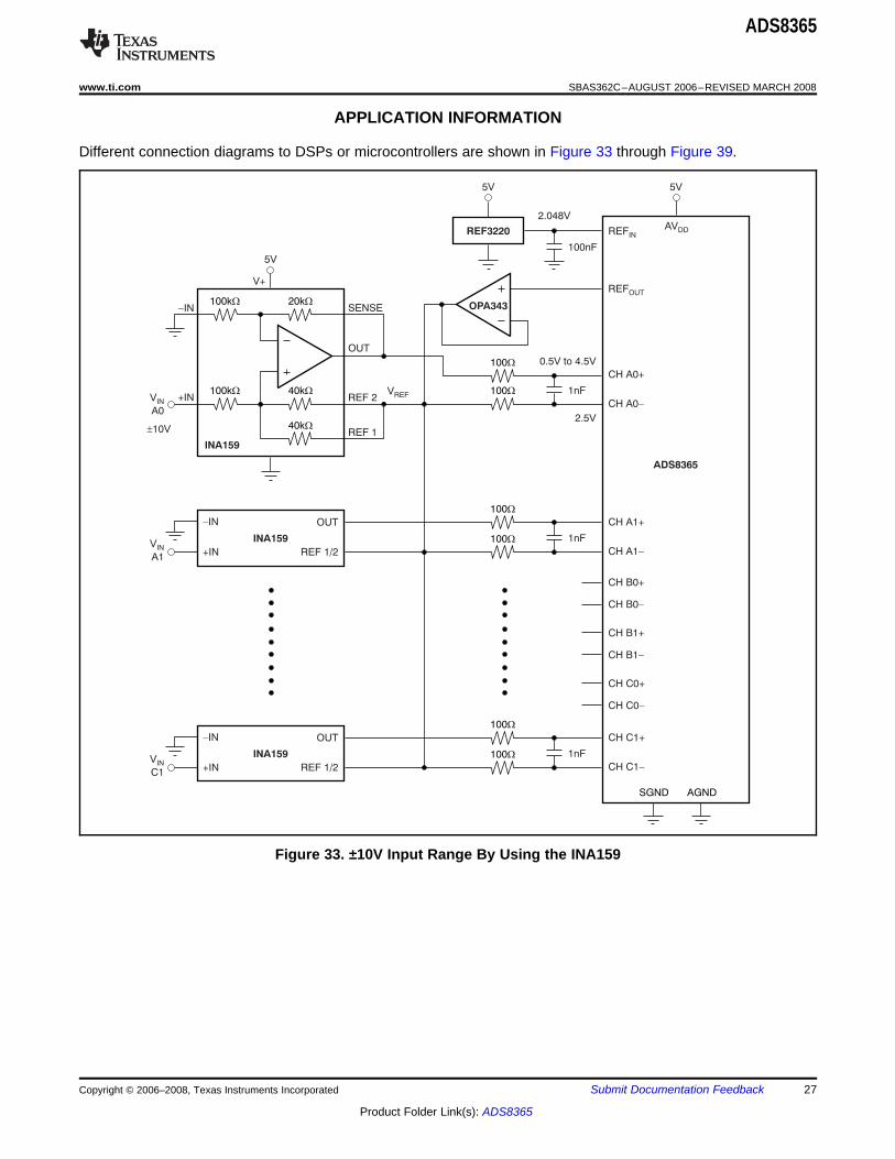
Different connection diagrams to DSPs or microcontrollers are shown in Figure 33 through Figure 39.
Figure 33. ±10V Input Range By Using the INA159
Copyright © 2006–2008, Texas Instruments Incorporated Submit Documentation Feedback 27
Product Folder Link(s): ADS8365

BVDD
HOLDA
HOLDB
HOLDC
A0
A1
A2
FD
WR
ADD
BYTE
DVDD
PWM1
PWM2
PWM3
EA0
EA1
EA2
EA3
CS
RD
EOC
CLK
RESET
BGND
DATA [0]...
DATA [15]
D0...
D15
IS
RE
EXT_INT1
MCLKX
ADC_RST (MFSX)
VSS
48
33...
8:1
OE
56
23
55
30
26
57
58
54
53
52
31
29
27
28
51
BVDD
3.3VADS8365 C28xx
BVDD
FD
ADD
BYTE
A0
A1
A2
DVDD
A2
A1
A0
CS
RD
EOC
CLK
BGND
DATA [0]...
DATA [15]
D0...
D15
IS
RE
EXT_INT1
MCLKX
VSS
48
33...
8:1
OE
56
23
55
26
53
52
54
57
58
31
29
30
27
28
BVDD3.3V
ADS8365 C28xx
WR WE
HOLDA
HOLDB
HOLDC
ADS8365
SBAS362C–AUGUST 2006–REVISED MARCH 2008.................................................................................................................................................... www.ti.com
Figure 34. Typical C28xx Connection (Hardware Control)
Figure 35. Typical C28xx Connection (Software Control)
28 Submit Documentation Feedback Copyright © 2006–2008, Texas Instruments Incorporated
Product Folder Link(s): ADS8365

BVDD
HOLDA
HOLDB
HOLDCA1
A2
ADD
A0
DVDD
TOUT1
A2
A1
A0
CS
BYTE
EOC
CLK
RESET
BGND
DAT [0]A...
DAT [15]A
D0...
D15
IS
BE0
INT0
TOUT0
DB_CNTL0 (ED27)
VSS
48
33...
8:1
OE
56
52
23
53
30
54
57
58
31
55
29
27
28
51
BVDD
3.3VADS8365 C67xx
RD
WR
RE
BVDD
FD
ADD
BYTE
A0
A1
A2
DVDD
A2
A1
A0
CS
RD
EOC
CLK
BGND
DAT [0]A...
DAT [15]A
D0...
D15
IS
RE
INT0
TOUT0
VSS
48
33...
8:1
OE
56
23
55
26
53
52
54
57
58
31
29
30
27
28
BVDD 3.3VADS8365 C67xx
WR WE
HOLDA
HOLDB
HOLDC
ADS8365
www.ti.com .................................................................................................................................................... SBAS362C–AUGUST 2006–REVISED MARCH 2008
Figure 36. Typical C67xx Connection (Cycle Mode—Hardware Control)
Figure 37. Typical C67xx Connection (Software Control)
Copyright © 2006–2008, Texas Instruments Incorporated Submit Documentation Feedback 29
Product Folder Link(s): ADS8365

BVDD
HOLDA
HOLDB
HOLDCFD
A0
A1
A2
WR
ADD
BYTE
DVDD
TOUT0
A2
A1
A0
CS
RD
EOC
CLK
RESET
BGND
DA A [0]T... ...
DA A [15]T
D0
D15
IS
I/OSTRB
INT0
BCLKX1
XF
VSS
48
33...
8:1
OE
56
23
55
26
53
52
30
54
57
58
31
29
30
27
28
51
BVDD
3.3VADS8365 C54xx
<
(1G32)
1
BVDD
HOLDA
HOLDB
HOLDC
WR
ADD
A1
A2
BYTE
A0
RD
DVDD
TACLK (P1.0)
P1.1CS
EOC
CLK
RESET
BGND
DAT [0]A...
DAT [7]A
P2.0...
P2.7
P1.2
P1.3 (ADC_INT)
VSS
48
41...
56
52
54
53
30
23
29
55
57
58
31
51
27
28
BVDD
3.3VADS8365 MSP430x1xx
SMCLK (P1.4)
ADS8365
SBAS362C–AUGUST 2006–REVISED MARCH 2008.................................................................................................................................................... www.ti.com
Figure 38. Typical C54xx Connection (FIFO Mode—Hardware Control)
Figure 39. Typical MSP430x1xx Connection (Cycle Mode—Hardware Control)
30 Submit Documentation Feedback Copyright © 2006–2008, Texas Instruments Incorporated
Product Folder Link(s): ADS8365

Part Change Notification # 20071210003
ADS8365
www.ti.com .................................................................................................................................................... SBAS362C–AUGUST 2006–REVISED MARCH 2008
The ADS8365 device underwent a silicon change under Texas Instruments Part Change Notification (PCN)number 20071210003. Details of this change can be obtained from the Product Information Center at TexasInstruments or by contacting your local sales/distribution office. Devices with a date code of 81x and higher arecovered by this PCN.
Copyright © 2006–2008, Texas Instruments Incorporated Submit Documentation Feedback 31
Product Folder Link(s): ADS8365

ADS8365
SBAS362C–AUGUST 2006–REVISED MARCH 2008.................................................................................................................................................... www.ti.com
Revision HistoryNOTE: Page numbers for previous revisions may differ from page numbers in the current version.
Changes from Revision B (November 2006) to Revision C ........................................................................................... Page
• Added Part Change Notification information........................................................................................................................ 31
32 Submit Documentation Feedback Copyright © 2006–2008, Texas Instruments Incorporated
Product Folder Link(s): ADS8365

PACKAGE OPTION ADDENDUM
www.ti.com 10-Jun-2014
Addendum-Page 1
PACKAGING INFORMATION
Orderable Device Status(1)
Package Type PackageDrawing
Pins PackageQty
Eco Plan(2)
Lead/Ball Finish(6)
MSL Peak Temp(3)
Op Temp (°C) Device Marking(4/5)
Samples
ADS8365IPAG ACTIVE TQFP PAG 64 160 Green (RoHS& no Sb/Br)
CU NIPDAU Level-4-260C-72 HR -40 to 85 ADS8365AI
ADS8365IPAGG4 ACTIVE TQFP PAG 64 160 Green (RoHS& no Sb/Br)
CU NIPDAU Level-4-260C-72 HR -40 to 85 ADS8365AI
ADS8365IPAGR ACTIVE TQFP PAG 64 1500 Green (RoHS& no Sb/Br)
CU NIPDAU Level-4-260C-72 HR -40 to 85 ADS8365AI
(1) The marketing status values are defined as follows:ACTIVE: Product device recommended for new designs.LIFEBUY: TI has announced that the device will be discontinued, and a lifetime-buy period is in effect.NRND: Not recommended for new designs. Device is in production to support existing customers, but TI does not recommend using this part in a new design.PREVIEW: Device has been announced but is not in production. Samples may or may not be available.OBSOLETE: TI has discontinued the production of the device.
(2) Eco Plan - The planned eco-friendly classification: Pb-Free (RoHS), Pb-Free (RoHS Exempt), or Green (RoHS & no Sb/Br) - please check http://www.ti.com/productcontent for the latest availabilityinformation and additional product content details.TBD: The Pb-Free/Green conversion plan has not been defined.Pb-Free (RoHS): TI's terms "Lead-Free" or "Pb-Free" mean semiconductor products that are compatible with the current RoHS requirements for all 6 substances, including the requirement thatlead not exceed 0.1% by weight in homogeneous materials. Where designed to be soldered at high temperatures, TI Pb-Free products are suitable for use in specified lead-free processes.Pb-Free (RoHS Exempt): This component has a RoHS exemption for either 1) lead-based flip-chip solder bumps used between the die and package, or 2) lead-based die adhesive used betweenthe die and leadframe. The component is otherwise considered Pb-Free (RoHS compatible) as defined above.Green (RoHS & no Sb/Br): TI defines "Green" to mean Pb-Free (RoHS compatible), and free of Bromine (Br) and Antimony (Sb) based flame retardants (Br or Sb do not exceed 0.1% by weightin homogeneous material)
(3) MSL, Peak Temp. - The Moisture Sensitivity Level rating according to the JEDEC industry standard classifications, and peak solder temperature.
(4) There may be additional marking, which relates to the logo, the lot trace code information, or the environmental category on the device.
(5) Multiple Device Markings will be inside parentheses. Only one Device Marking contained in parentheses and separated by a "~" will appear on a device. If a line is indented then it is a continuationof the previous line and the two combined represent the entire Device Marking for that device.
(6) Lead/Ball Finish - Orderable Devices may have multiple material finish options. Finish options are separated by a vertical ruled line. Lead/Ball Finish values may wrap to two lines if the finishvalue exceeds the maximum column width.
Important Information and Disclaimer:The information provided on this page represents TI's knowledge and belief as of the date that it is provided. TI bases its knowledge and belief on informationprovided by third parties, and makes no representation or warranty as to the accuracy of such information. Efforts are underway to better integrate information from third parties. TI has taken and

PACKAGE OPTION ADDENDUM
www.ti.com 10-Jun-2014
Addendum-Page 2
continues to take reasonable steps to provide representative and accurate information but may not have conducted destructive testing or chemical analysis on incoming materials and chemicals.TI and TI suppliers consider certain information to be proprietary, and thus CAS numbers and other limited information may not be available for release.
In no event shall TI's liability arising out of such information exceed the total purchase price of the TI part(s) at issue in this document sold by TI to Customer on an annual basis.

TAPE AND REEL INFORMATION
*All dimensions are nominal
Device PackageType
PackageDrawing
Pins SPQ ReelDiameter
(mm)
ReelWidth
W1 (mm)
A0(mm)
B0(mm)
K0(mm)
P1(mm)
W(mm)
Pin1Quadrant
ADS8365IPAGR TQFP PAG 64 1500 330.0 24.4 13.0 13.0 1.5 16.0 24.0 Q2
PACKAGE MATERIALS INFORMATION
www.ti.com 14-Jul-2012
Pack Materials-Page 1

*All dimensions are nominal
Device Package Type Package Drawing Pins SPQ Length (mm) Width (mm) Height (mm)
ADS8365IPAGR TQFP PAG 64 1500 367.0 367.0 45.0
PACKAGE MATERIALS INFORMATION
www.ti.com 14-Jul-2012
Pack Materials-Page 2

MECHANICAL DATA
MTQF006A – JANUARY 1995 – REVISED DECEMBER 1996
POST OFFICE BOX 655303 • DALLAS, TEXAS 75265
PAG (S-PQFP-G64) PLASTIC QUAD FLATPACK
0,13 NOM
0,25
0,450,75
Seating Plane
0,05 MIN
4040282/C 11/96
Gage Plane
33
0,170,27
16
48
1
7,50 TYP
49
64
SQ
9,80
1,050,95
11,8012,20
1,20 MAX
10,20SQ
17
32
0,08
0,50 M0,08
0°–7°
NOTES: A. All linear dimensions are in millimeters.B. This drawing is subject to change without notice.C. Falls within JEDEC MS-026


IMPORTANT NOTICE
Texas Instruments Incorporated (TI) reserves the right to make corrections, enhancements, improvements and other changes to itssemiconductor products and services per JESD46, latest issue, and to discontinue any product or service per JESD48, latest issue. Buyersshould obtain the latest relevant information before placing orders and should verify that such information is current and complete.TI’s published terms of sale for semiconductor products (http://www.ti.com/sc/docs/stdterms.htm) apply to the sale of packaged integratedcircuit products that TI has qualified and released to market. Additional terms may apply to the use or sale of other types of TI products andservices.Reproduction of significant portions of TI information in TI data sheets is permissible only if reproduction is without alteration and isaccompanied by all associated warranties, conditions, limitations, and notices. TI is not responsible or liable for such reproduceddocumentation. Information of third parties may be subject to additional restrictions. Resale of TI products or services with statementsdifferent from or beyond the parameters stated by TI for that product or service voids all express and any implied warranties for theassociated TI product or service and is an unfair and deceptive business practice. TI is not responsible or liable for any such statements.Buyers and others who are developing systems that incorporate TI products (collectively, “Designers”) understand and agree that Designersremain responsible for using their independent analysis, evaluation and judgment in designing their applications and that Designers havefull and exclusive responsibility to assure the safety of Designers' applications and compliance of their applications (and of all TI productsused in or for Designers’ applications) with all applicable regulations, laws and other applicable requirements. Designer represents that, withrespect to their applications, Designer has all the necessary expertise to create and implement safeguards that (1) anticipate dangerousconsequences of failures, (2) monitor failures and their consequences, and (3) lessen the likelihood of failures that might cause harm andtake appropriate actions. Designer agrees that prior to using or distributing any applications that include TI products, Designer willthoroughly test such applications and the functionality of such TI products as used in such applications.TI’s provision of technical, application or other design advice, quality characterization, reliability data or other services or information,including, but not limited to, reference designs and materials relating to evaluation modules, (collectively, “TI Resources”) are intended toassist designers who are developing applications that incorporate TI products; by downloading, accessing or using TI Resources in anyway, Designer (individually or, if Designer is acting on behalf of a company, Designer’s company) agrees to use any particular TI Resourcesolely for this purpose and subject to the terms of this Notice.TI’s provision of TI Resources does not expand or otherwise alter TI’s applicable published warranties or warranty disclaimers for TIproducts, and no additional obligations or liabilities arise from TI providing such TI Resources. TI reserves the right to make corrections,enhancements, improvements and other changes to its TI Resources. TI has not conducted any testing other than that specificallydescribed in the published documentation for a particular TI Resource.Designer is authorized to use, copy and modify any individual TI Resource only in connection with the development of applications thatinclude the TI product(s) identified in such TI Resource. NO OTHER LICENSE, EXPRESS OR IMPLIED, BY ESTOPPEL OR OTHERWISETO ANY OTHER TI INTELLECTUAL PROPERTY RIGHT, AND NO LICENSE TO ANY TECHNOLOGY OR INTELLECTUAL PROPERTYRIGHT OF TI OR ANY THIRD PARTY IS GRANTED HEREIN, including but not limited to any patent right, copyright, mask work right, orother intellectual property right relating to any combination, machine, or process in which TI products or services are used. Informationregarding or referencing third-party products or services does not constitute a license to use such products or services, or a warranty orendorsement thereof. Use of TI Resources may require a license from a third party under the patents or other intellectual property of thethird party, or a license from TI under the patents or other intellectual property of TI.TI RESOURCES ARE PROVIDED “AS IS” AND WITH ALL FAULTS. TI DISCLAIMS ALL OTHER WARRANTIES ORREPRESENTATIONS, EXPRESS OR IMPLIED, REGARDING RESOURCES OR USE THEREOF, INCLUDING BUT NOT LIMITED TOACCURACY OR COMPLETENESS, TITLE, ANY EPIDEMIC FAILURE WARRANTY AND ANY IMPLIED WARRANTIES OFMERCHANTABILITY, FITNESS FOR A PARTICULAR PURPOSE, AND NON-INFRINGEMENT OF ANY THIRD PARTY INTELLECTUALPROPERTY RIGHTS. TI SHALL NOT BE LIABLE FOR AND SHALL NOT DEFEND OR INDEMNIFY DESIGNER AGAINST ANY CLAIM,INCLUDING BUT NOT LIMITED TO ANY INFRINGEMENT CLAIM THAT RELATES TO OR IS BASED ON ANY COMBINATION OFPRODUCTS EVEN IF DESCRIBED IN TI RESOURCES OR OTHERWISE. IN NO EVENT SHALL TI BE LIABLE FOR ANY ACTUAL,DIRECT, SPECIAL, COLLATERAL, INDIRECT, PUNITIVE, INCIDENTAL, CONSEQUENTIAL OR EXEMPLARY DAMAGES INCONNECTION WITH OR ARISING OUT OF TI RESOURCES OR USE THEREOF, AND REGARDLESS OF WHETHER TI HAS BEENADVISED OF THE POSSIBILITY OF SUCH DAMAGES.Unless TI has explicitly designated an individual product as meeting the requirements of a particular industry standard (e.g., ISO/TS 16949and ISO 26262), TI is not responsible for any failure to meet such industry standard requirements.Where TI specifically promotes products as facilitating functional safety or as compliant with industry functional safety standards, suchproducts are intended to help enable customers to design and create their own applications that meet applicable functional safety standardsand requirements. Using products in an application does not by itself establish any safety features in the application. Designers mustensure compliance with safety-related requirements and standards applicable to their applications. Designer may not use any TI products inlife-critical medical equipment unless authorized officers of the parties have executed a special contract specifically governing such use.Life-critical medical equipment is medical equipment where failure of such equipment would cause serious bodily injury or death (e.g., lifesupport, pacemakers, defibrillators, heart pumps, neurostimulators, and implantables). Such equipment includes, without limitation, allmedical devices identified by the U.S. Food and Drug Administration as Class III devices and equivalent classifications outside the U.S.TI may expressly designate certain products as completing a particular qualification (e.g., Q100, Military Grade, or Enhanced Product).Designers agree that it has the necessary expertise to select the product with the appropriate qualification designation for their applicationsand that proper product selection is at Designers’ own risk. Designers are solely responsible for compliance with all legal and regulatoryrequirements in connection with such selection.Designer will fully indemnify TI and its representatives against any damages, costs, losses, and/or liabilities arising out of Designer’s non-compliance with the terms and provisions of this Notice.
Mailing Address: Texas Instruments, Post Office Box 655303, Dallas, Texas 75265Copyright © 2018, Texas Instruments Incorporated