Embed Size (px)
Citation preview

PERPUSTAKAAN UMP
111111111111111111111 flU 0000098319
MECHANICAL PROPERTIES OF LIGHWEIGHT CONCRETE
ARCH PAN
MUHAMMAD AIZAT BIN ABD GHAFAR
Project report submitted as partial fulfilment of the requirements for the award of the
degree of B. Eng. (Hons) Civil Engineering
Faculty of Civil Engineering & Earth Resources
UNIVERSITY MALAYSIA PAHANG
JANUARY 2015

vi
ABSTRACT
Nowadays, permanent formwork using arch pan have emerged and been applied widely
rather than using conventional method, temporary formwork which is more expensive
and produce a lot of wastage in term of time and workers. Recently, permanent
formwork is using normal concrete which lead many problem such as the uses of
scaffolding. Normal weight concrete is widely used in constructions which provide a
balance of strength, workability, durability and economy for general use. However the
self-weight beam is too heavy. One of the alternatives to overcome the problems is
using lightweight concrete. The objective of the study is to determine the mix design
that will produce concrete arch pan that can carry a minimum load of 1 kN, using foam
lightweight concrete. This project study also is carried out to determine the strength of
lightweight concrete arch pan. Compressive tests and flexural test were carried out for
the project report. The strength of lightweight concrete was measured through the test.
This research includes the design and fabrication of the arch pan by using the foam
lightweight concrete. Based on the result obtained from the testing, it shows that the
strength of lightweight concrete arch pan is increasing steadily with time.

vii
ABSTRAK
Pada masa kini, acuan tetap menggunakan pan gerbang telah muncul dan telah
digunakan secara meluas daripada menggunakan kaedah konvensional, acuan sementara
yang lebih mahal dan menghasilkan banyak pembaziran dari segi masa dan pekerja.
Baru-baru mi, adalah acuan kekal menggunakan konkrit biasa yang menyebabkan
masalah banyak seperti penggunaan perancah. Konkrit berat badan normal digunakan
secara meluas dalam pembinaan yang memberikan keseimbangan kekuatan,
kebolehkerjaan, ketahanan dan ekonomi untuk kegunaan umum. Walau bagaimanapun
rasuk berat diri terlalu berat. Salah satu alternatif untuk mengatasi masalah
menggunakan konkrit ringan. Objektif kajian mi adalah untuk menentukan reka bentuk
campuran yang akan menghasilkan pan gerbang konkrit yang boleh membawa muatan
minimum 1 kN, menggunakan busa konkrit ringan. Kajian projek ini juga dijalankan
untuk menentukan kekuatan ringan pan gerbang konkrit. Ujian mampatan dan ujian
lenturan dijalankan bagi laporan projek. Kekuatan konkrit ringan telah diukur melalui
ujian. Kajian ini termasuk dalam reka bentuk dan reka pan gerbang dengan
menggunakan konkrit busa ringan. Berdasarkan keputusan yang diperolehi daripada
ujian itu, ia menunjukkan bahawa kekuatan ringan pan gerbang konkrit semakin
meningkat dengan mantap dengan masa.

viii
TABLE OF CONTENTS
SUPERVISOR'S DECLARATION
STUDENT'S DECLARATION
ACKNOWLEDGEMENT v
ABSTRACT vi
ABSTRAK vii
TABLE OF CONTENTS viii
LIST OF TABLES xii
LIST OF FIGURES xiii
EQUATION xiv
CHAPTER 1 1
INTRODUCTION 1
1.1 Background of Study 1
1.2 Problem Statement 2
1.3 Research Objectives 3
1.4 Research Questions 3
1.5 Scope of Study 3
1.6 Significance of Research 4
CHAPTER 2 5
LITERATURE REVIEW 5
2.1 Introduction 5
2.2 Overview of foamed concrete 5
2.2.1 Definition of foamed concrete 6
2.2.2 History and background of foamed concrete 6
2.2.3 Comparison between foam concrete and conventional concrete 7
2.2.4 Manufacture of foamed concrete 8
2.2.5 Basic material 8
1. Portland cement 8

lx
2. Fine aggregate 9
3. Water 9
4. Foamed Agent 10
2.2.6 Equipment 11
2.2.7 Mixing procedures 11
2.2.8 Curing of foamed concrete 12
2.2.9 Benefit of foamed concrete 12
2.3 Permanent Formwork 12
2.4 Examples of Permanent Formwork 13
a) Rib and Block Suspended Slab 13
b) Composite Slab Construction 14
2.5 The Advantages of Permanent Formwork 14
2.6 Concept of Arch 15
2.7 Concept of Arch in Slab Construction 16
a) Jack Arch Masonry Flooring System 16
b) Clay Tile Arch Floor System 17
C) Brick Arch Floor System 19
CHAPTER 3 20
METHODOLOGY 20
3.1 Introduction 20
3.2 Sample preparing 22
3.2.1 Cement 22
3.2.2 Foaming agent 22
3.2.3 Silica Sand 23
3.2.4 Plywood 23
3.2.4.1 Design Arch Pan Formwork 24
3.2.4.2 Construction Process of Arch Pan Formwork 27

x
3.2.5 Mix Design Strength 27
3.2.5.1 Mix Proportion Design 28
3.3 Laboratory Testing 30
3.3.1' Concreting Equipment 30
3.3.2' Concreting Process 31
3.3.3' Concrete Compression Test (ASTM BS 1881: Part 116: 1983) 32
3.3.4 Flexural Test On BEAM (ASTM E4-Standard Practices for Force
Verification of Testing Machines) 34
3.3.5 Arch Pan Test (FLEXURAL Test On Arch) 35
3.4 Data Analysis 37
3.5 Gantt Chart 37
CHAPTER 4 39
RESULT AND ANALYSIS 39
4.1 Cube 39
4.1.1 Compressive Strength Test 39
4.1.2 Graph Analysis 40
4.2 Beam 41
4.2.1 Flexural Stength 41
4.2.2 Graph Analysis 42
4.3 Arch 44
4.3.1 Flexural Strength 44
4.3.2 Graph Analysis 45
4.4 Crack Pattern 47
4.4.1 Cube 48
4.4.2 Beam 49
4.4.3 Arch 51
CHAPTER 5

xi
CONCLUSION AND RECOMMENDATION 53
5.1 Conclusion 53
5.2 Recommendation 54
REFERENCES 55
APPENDIX A 57
APPENDIX B 62
APPENDIX C 67
APPENDIX 72
APPENDIX 76
APPENDIX F 78

LIST OF TABLES
Table 1 Casting Volume of mould .28
Table 2 Preparation of Sample.....................................................................................29 Table3 Casting Design ...............................................................................................30 Table4 Equipment ......................................................................................................31 Table 5 Compressive Strength of Cubes ......................................................................39 Table 6 Flexural Strength of Beam ..............................................................................42 Table 7 Flexural Strength of Arch ............................................................................... 45
xii

xiii
LIST OF FIGURES
Figure 1 Example of ribs and block suspended slab construction................................. 13 Figure 2 Example of composite slab construction........................................................ 14 Figure 3 2-pinned Symmetrical Parabolic Arch ........................................................... 16 Figure 4 One way jack arch slab configuration ............................................................ 17 Figure 5 Segmental clay tile arch floor detail............................................................... 18 Figure 6 Floor Flat clay tile detail................................................................................ 19 Figure 7 Brick arch floor system.................................................................................. 19 Figure 8 Methodology Process .................................................................................... 21 Figure 9 Arch Pan Mould Dimension (all units in cm)................................................. 26 Figure 10 Arch Pan Dimension (all units in cm) .......................................................... 26 Figure 11 Step by step process of arch pan mould ......................................................... 27 Figure 12 Mix Design Strength .......................................... .......................................... 27 Figure 13 Concreting Process ...................................................................................... 32 Figure 14 Compression Machine Test.......................................................................... 33 Figure 15 Compression Testing Procedure................................................................... 33 Figure 16 Universal Material Tester ............................................................................ 34 Figure 17 Flexural Testing Procedure of Beam............................................................ 35 Figure 18 Universal Testing Machine.......................................................................... 36 Figure 19 Flexural Testing Procedure for Arch............................................................ 36 Figure 20 Graph Strength vs. Days .............................................................................. 40 Figure 21 Graph Max Force vs. Days .......................................................................... 41 Figure 22 Graph Flexural Strength vs Days ................................................................. 43 Figure 23 Graph Maximum Force vs Displacement ..................................................... 44 Figure 24 Graph Flexural Strength vs Days ................................................................. 46 Figure 25 Graph Max. Force vs Displacement............................................................. 47 Figure 26 Cracking Pattern for Day 7 .......................................................................... 48 Figure 27 Cracking Pattern for Day 14 ........................................................................ 48 Figure 28 Cracking Pattern for Day 28 ........................................................................ 49 Figure 29 Cracking Pattern for Day 7 .......................................................................... 49 Figure 30 Cracking Pattern for Day 14 ........................................................................ 50 Figure 31 Cracking Pattern for Day 28 ........................................................................ 50 Figure 32 Cracking Pattern for Day 7 .......................................................................... 51 Figure 33 Cracking Pattern for Day 14 ........................................................................ 51 Figure 34 Cracking Pattern for Day 28 ........................................................................ 52

xlv
EQUATION
Equation 1 Relationship between horizontal and vertical distance................................24 Equation 2 Moment equation....................................................................................... 25
Equation 3 Maximum shear stress and normal stress equation .....................................25
Equation 4 Relationship between Foam Density and Mortar Density...........................28 Equation 5 Volume of arch..........................................................................................29 Equation 6 Volume Casting Equation..........................................................................30

CHAPTER 1
INTRODUCTION
1.1 BACKGROUND OF STUDY
In the construction industry, there are always new technologies developed
especially in building construction. Nowadays, permanent formwork using arch pan
have emerged and been applied widely rather than using conventional method,
temporary formwork which is more expensive and produce a lot of wastage in term of
time and workers. Referring to Kamran M. Nemati (2007), permanent formwork is a
structural element that contains the placed concrete, mould it to the required dimensions
and it will remain in place for the lifetime of the structure. Recently, permanent
formwork is using normal concrete which lead many problem such as the uses of
scaffolding.
By referring to J.L Clarke (1993), the definition for lightweight concrete is one
having an air-dry density of less than 1810 kg/m3. It is this true that the application of
lightweight concrete is limited to certain purposes compared to normal concrete, but the
introduction of lightweight concrete gives more alternative to construction industry,
which currently focuses on natural resources. In this research, the main focus is to
establish the uses of lightweight concrete which is foamed concrete in the arch pan.

2
1.2 PROBLEM STATEMENT
In normal construction for the flooring system, the amount of scaffolding use is
higher. By apply the arch pan system in the flooring system, it help to eliminate the use
of the scaffolding. Normal weight concrete is widely used in constructions which
provide a balance of strength, workability, durability and economy for general use.
However the self-weight beam is too heavy. One of the alternatives to overcome the
problems is using lightweight concrete. Lightweight concrete used to reduce the dead
load, to faster construction time, lower haulage and handling cost. However, lightweight
concrete is lower in strength although it is lighter.
In Malaysia the use of lightweight concrete is not very common; this may be due
to large amount of gravel aggregate still available in the market. Based on the statement,
we know that the construction industry in Malaysia have a problem which may be it is
not popular relating expensive cost, less knowledge and experience, not having enough
the skill worker, the machinery and appliance to constructed the lightweight concrete
not enough.
It is this true that the application of lightweight concrete is limited to certain
purposes compared to normal concrete, but the introduction of lightweight concrete
gives more alternative to construction industry. Some of the lightweight aggregate are
manufactured from waste material such as Lytag, whereby it was produced from
pulverized fuel ash (PFA) and natural materials, like volcanic pumice. Thus this
research wills emphasize on mix design of lightweight concrete.

3
1.3 RESEARCH OBJECTIVES
The main objectives of this research are as follow:
1.3.1 To identify the compressive and flexural strength properties of lightweight
concrete
1.3.2 To design and fabricate the arch pan using lightweight concrete
1.3.3 To determine the flexural strength on arch pan exceeding lkN force
1.4 RESEARCH QUESTIONS
1.4.1 How to increase compressive and flexural strength of lightweight concrete?
1.4.2 What is the mix design of the lightweight concrete?
1.4.3 What is the maximum load that can be applied?
1.5 SCOPE OF STUDY
This research is conduct:
1.5.1 To explore the mix design of lightweight concrete
1.5.2 To prepare the sample of lightweight concrete to use in the arch pan
1.5.3 To put the sample on the compression machine and the force is applied to collect
the data
1.5.4 To determine the flexural strength by using flexural machine test
1.5.5 To put the sample on the flexural machine test and the load is applied on the
sample to collect the data

1.6 SIGNIFICANCE OF RESEARCH
In this research, the main purpose is to produce standard design on arch pan
system using lightweight concrete. Economically by using lightweight concrete, it will
reduce the cost to produce the concrete. Besides by using lightweight concrete help in
the reduction of dead load and faster construction time.
4
CHAPTER 2
LITERATURE REVIEW
2.1 INTRODUCTION
Light weight foamed concrete has become more popular in recent years owing
to the tremendous advantages it offers over the conventional concrete. Modern
technology and a better understanding of the concrete have also helped much in the
promotion and use of light weight foamed concrete on concrete arch pan.
This chapter describes the nature of foamed concrete, its composition and
properties and how it use in concrete arch pan. Because the properties of foamed
concrete can vary widely, and it can be used in a wide variety of applications, it is
important to define performance requirements for each case.
2.2 OVERVIEW OF FOAMED CONCRETE
5

2.2.1 DEFINITION OF FOAMED CONCRETE
Foamed concrete has been defined in several ways; indeed it has number of
synonyms such as cellular concrete and there is confusion between foamed concrete and
similar materials such as air entrained concrete. A definition, cited by Jones (2005), is
that foamed concrete is a cementation material having a minimum of 20 per cent (by
volume) of mechanically entrained foam in the plastic mortar. This differentiates
foamed concrete from:
(a) Gas or aerated concrete, where the bubbles are chemically formed through
the reaction of aluminium powder with calcium hydroxide and other alkalis released by
cement hydration.
(b) Air entrained concrete, which has a much lower volume of entrained air.
Other definition, according to Aldridge (2005), that the term foamed concrete is
itself misleading with vast majority of concretes containing no large aggregates, only
fine sand and with the extremely light weight foamed concrete materials containing
only cement, water and foamed, so the product should'be more accurately described as
having an air content of more than 25%which distinguishes it from highly air entrained.
In it is basic form foamed concrete is blend of sand ,cement ,water and pre-formed
foam, which in itself is a mixture of foaming agent (either synthetic or protein base),
water and air.
2.2.2 HISTORY AND BACKGROUND OF FOAMED CONCRETE
Foamed concrete is not a particularly new material, it is first recorded use date
back to the early 1920s. The application of foamed concrete for construction works was
not recognized until the late 1970s, when it began to be used in Sweden in 1929s.

7
The first large foamed concrete project in the UK was completed in 1980 at the
Falkirk Railway Tunnel in Scotland. Around 4500m3 of 1100 kg/m3 foamed concrete
was placed in the annulus space surrounding the tunnel. The largest project in the UK
required around 70,000m3 of 500kg/m3 foamed concrete encapsulating the utilities
supply pipe and cable in the road foundation at Canary Wharf in London.
Significant improvements in production methods and quality of foaming agent
over the last 16 years have led to increased production of wide range of application such
as blocks, void fill and road. From there on, the use of Foamed concrete has been
widely spread across world-wide (Andrew & William, 1978).
2.2.3 COMPARISON BETWEEN FOAM CONCRETE AND CONVENTIONAL
CONCRETE
Lightweight foamed concrete made with combination of cement, water, fine
aggregate and foam agent have very fine pore structure, unlike that made with
conventional concrete.
Foam or bubbling agent is used to absorb humidity for as long as the product is
exposed to the atmosphere, allowing the hydration process of the cement to continue for
its ever-continuing strength development.
As in a normal concrete the greater the air content the weaker the material, so
with foamed concrete densities ranging from 300 to 1700 kg/m3 it is not surprising that
the lower densities produce the lower strengths and at present even the densities at the
upper limits do not produce strengths much above 15 N/mm2 (Aldridge,2005).

8
2.2.4 MANUFACTURE OF FOAMED CONCRETE
Foamed concrete is produced by entrapping numerous small bubbles of air in
cement paste or mortar. Mechanical foaming can take place in two principal ways:
By pre-foaming a suitable foaming agent with water and then combining the
foam with paste or mortar.
By adding a quantity of foaming agent to the slurry and whisking the mixture
into a stable mass with the required density.
To get a high performance and quality foamed concrete, the selection of the
materials are very important. The various materials, equipment and procedure are
discussed separately below.
2.2.5 BASIC MATERIAL
1. PORTLAND CEMENT
There are many types of Portland cement .high alumina cement; super sulphate
and special cement as masonry. Under ASTM standard the type (I, II, III) is preferred to
use because its fineness and chemical composition.
However, Ordinary Portland cement (to BS 12:1996 or BS EN 197: Part 1:
2000) is usually used as tile main binder for foamed concrete. However rapid-hardening
Portland cement to BS 915:1983 has also been used, and there does not seem to be any
evidence why sulphate resisting cement could not be used.

Portland cement is essentially calcium silicate cement, which is produced by
firing to partial fusion, at high temperature approximately 1500 C°. It has different
rheological and strength characteristics, especially use in combination with chemical
admixtures and supplementary cementing materials. Therefore, it is necessary to look at
its fitness and chemistry content when choosing.
2. FINE AGGREGATE
Generally the fine aggregate shall consist of natural sand, manufactured sand or
combination of them. The fine aggregate for concrete that subjected wetting, extended
exposure to humid atmosphere, or contact with moist ground shall not contain any
material that deleteriously reactive in cement to cause excessive expansion of mortar
concrete.
Recommend that only fine sands suitable for concrete (to BS 882:1992) or
mortar (to BS 1200: 1976) having particle sizes up to about 4 mm and with an even
distribution of sizes should be used for foamed concrete. This is mainly because coarser
aggregate might settle in a lightweight mix and lead to collapse of the foam during
mixing.
3. WATER
The water used for foamed concrete should be potable. This is crucial when
using a protein based foaming agent because organic contamination can have an adverse
effect on the quality of the foam, and hence the concrete produced.
The water/cement (w/c) ratio of the base mix required to achieve adequate
workability is dependent upon the type of binder(s), the required strength of the
concrete, and whether or not a water reducing or a plasticizing agent has been used. In

10
most cases the value will be between 0.4 and 0.8. The higher values are required with
fmer grained binders, such as PFA, and the lower values where either a high strength is
required or a super plasticizer has been employed.
Where the water content of the mix would be inadequate to ensure full hydration
of the cement, water will be extracted from the foam and might lead to its
disintegration. On the other hand whilst high w/c ratios do not significantly affect the
porosity of the foamed concrete they do promote segregation and increase drying
shrinkage (Gambhir, 2004).
4. FOAMED AGENT
Synthetic or protein-based foaming agents (surfactants) can be used to produce
foam. Because of the possibility of degradation by bacteria and other organisms, natural
protein based agents (i.e. fatty acid soaps) are rarely used to produce foamed concrete
for civil engineering works. However research is underway on the use of protein-based
agents for developing high strength, i.e... The chemical composition of surfactants must
be stable in the alkaline environment of concrete. Because all surfactants are susceptible
to deterioration at low temperatures they should be stored accordingly. The properties of
foamed concrete are critically dependent upon the quality of the foam. There are two
types of foaming agent:
I. Synthetic-suitable for densities of 1000 kg/m3 and above.
II. Protein-suitable for densities from 400 to 1600 kg/m3.
Protein-based foaming agents come from animal proteins out of horn, blood,
bones of cows, pigs and other remainders of animal carcasses. Its surfactants might
therefore be best suited to the production of foamed concrete of relatively high density

I
and high strength. Optimum performance of foam is commonly attained at a ratio of
1:25, but the optimum value is a function of the type of surfactant and the method of
production (Gambhir, 2004).
2.2.6 EQUIPMENT
The production of foamed concrete is a fairly easy process which does not
involve any expensive or heavy machinery and in most cases uses equipment that is
already available for normal concrete/mortar production. That include:
1. Normal concrete/mortar mixer or special mixers for foam concrete.
2. Foam Generator
3. Formwork (if producing pre- cast components)
2.2.7 MIXING PROCEDURES
At first start with the sand and cement. Mix dry constituents for a few minutes
and add water in stages and make sure the mixing is thorough (Mortar slurry
preparation). Then, Preparation of pre-foamed by diluted the foam agent with water and
extracted by using foam generator and air compressor. After that, add foam to the wet
slurry and ensure foam has been completely mixed with the mortar. After mixing is
completed check that the wet density of the foamed concrete is close to what is
required.
There is no chemical reaction involved when the pre-foamed add into the
cement mortar. Introduction of pores is achieved through mechanical means either by
pre-formed foamed foaming (foaming agent mixed with part of mixing water) or mix
foaming (foaming agent mixed with the mortar) (Yew,2007).
12
2.2.8 CURING OF FOAMED CONCRETE
Curing is a process of preventing fleshly placed concrete from drying the first
during the first day of its life to minimize any tendency to cracking and allow it to
develop concrete strength. There are different methods of curing that affect the concrete
properties as: water curing, sheet curing, membrane curing and air curing.
2.2.9 BENEFIT OF FOAMED CONCRETE
Foamed contribute to the reduction of building dead weight thus resulting in
more economic structural design. Production of more economic structural design will
reduce the amount of material used and eventually cutting down the cost of construction
project itself resulting in profit increase to the contractor.
Besides that, other researchers added that the lightness of structure makes it
easier to be transported and handled. In addition, it's also has a very low thermal
conductivity that makes it an excellent fire protection property (John& Ban Choo,
2003).
2.3 PERMANENT FORMWORK
A permanent formwork is a formwork that stays in place for the life of the
element it is supporting and becomes a part of the permanent structure of the building. It
does not only act as a temporary support to control the shape of the fluid concrete, but it
also help to strength the finished concrete structure. They are various types of materials
that are being used in generating the permanent formwork including timber, steel
decking sheet, concrete, glass reinforced concrete, plastic, fibre-cement form board and
Poly
styrene. The applicability of each material will depend on the requirement
durability, strength and appearance of each case.
13
For a permanent formwork, it must be strong enough to carry the pressure that
the fluid concrete can exert. Then, the strength of permanent formwork must endure
until the concrete is self-supporting. These characteristic must have in a permanent
formwork to enable the structure is durable and have a long life.
2.4 EXAMPLES OF PERMANENT FORMWORK
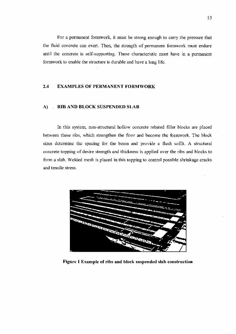
A) RIB AND BLOCK SUSPENDED SLAB
In this system, non-structural hollow concrete rebated filler blocks are placed
between these ribs, which strengthen the floor and become the formwork. The block
sizes determine the spacing for the beam and provide a flush soffit. A structural
concrete topping of desire strength and thickness is applied over the ribs and blocks to
form a slab. Welded mesh is placed in this topping to control possible shrinkage cracks
and tensile stress.
Figure 1 Example of ribs and block suspended slab construction
14
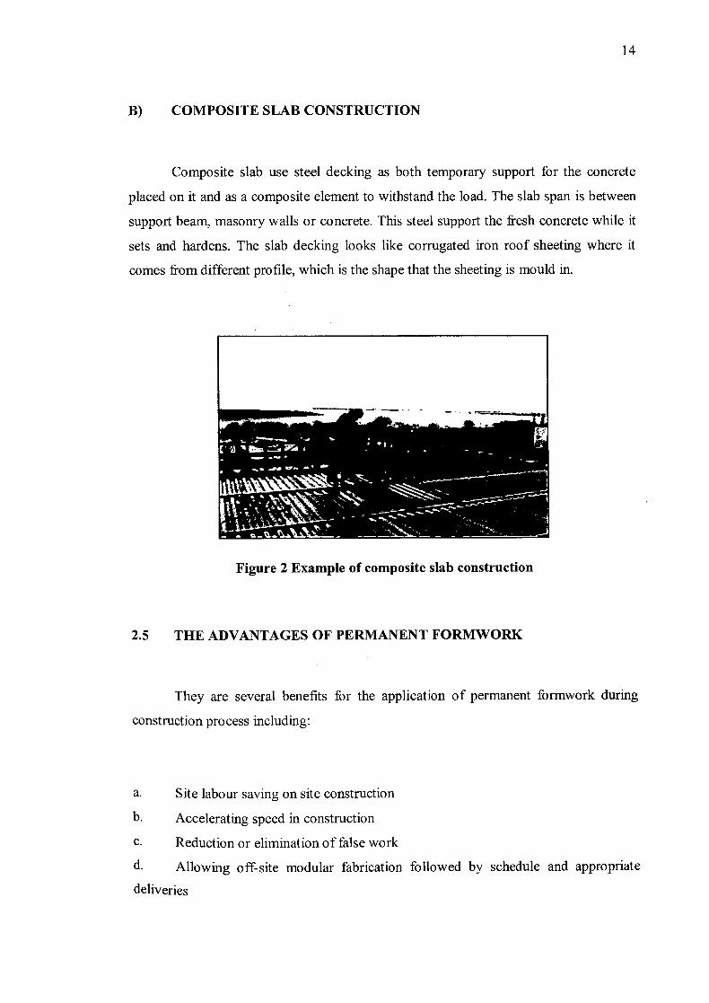
B) COMPOSITE SLAB CONSTRUCTION
Composite slab use steel decking as both temporary support for the concrete
placed on it and as a composite element to withstand the load. The slab span is between
support beam, masonry walls or concrete. This steel support the fresh concrete while it
sets and hardens. The slab decking looks like corrugated iron roof sheeting where it
comes from different profile, which is the shape that the sheeting is mould in.
Figure 2 Example of composite slab construction
2.5 THE ADVANTAGES OF PERMANENT FORMWORK
They are several benefits for the application of permanent formwork during
construction process including:
a. Site labour saving on site construction
b. Accelerating speed in construction
C. Reduction or elimination of false work
d. Allowing off-site modular fabrication followed by schedule and appropriate
deliveries


![[PPT]PENYAKIT FLU BURUNG - Keluarga IKMA FKMUA … · Web viewPENYAKIT FLU BURUNG * * * * * * * * * * * * * * * * * * * EPIDEMIOLOGI Penyebab FLU BURUNG FLU burung atau flu unggas](https://img.dokumen.tips/doc/110x75/5ae835287f8b9a8b2b8facf5/pptpenyakit-flu-burung-keluarga-ikma-fkmua-viewpenyakit-flu-burung-.jpg)