Embed Size (px)
Citation preview

1048, Page 1
23rd
International Compressor Engineering Conference at Purdue, July 11-14, 2016
The Effects of Blade Fillets on Aerodynamic Performance
of a High Pressure Ratio Centrifugal Compressor
Justin (Jongsik) Oh
Danfoss Turbocor Compressors, Inc.
Tallahassee, FL
ABSTRACT
In most cases of aerodynamic design of centrifugal compressors, the effects of impeller blade fillets on performance
are not considered in the process, but could be estimated later from some limited studies. As one of numerical
investigations for the effects in centrifugal compressors, the Krain backswept impeller was modeled with and
without blade fillets on the hub. A vaneless diffuser and impeller tip clearances were included in the steady state
analysis using a commercial CFD code. Over the range of flows at design speed, the case with blade fillets showed a
slight drop in the pressure ratio, the efficiency, the choke flow and the range of operation, relative to the case of
clean blades. A more detailed look into three-dimensional flow structure inside the impeller shows that a small
scraping vortex, developed in the case of clean blades at the corner of the hub pressure surface, disappears in the case
with blade fillets due to a local flow acceleration produced by the fillet. As a result of balancing forces acting in the
impeller passage, it was observed that the shroud passage vortex in the case with blade fillets grows toward the
impeller exit with a higher vortex core than that in the case of clean blades, which means that there are more wake
flows with blade fillets, leading to aerodynamic performance drops.
1. INTRODUCTION
Fillets around the interface of blades with endwalls are generally required in the turbomachinery
manufacturing process such as the 5-axis machining or a simple welding. Even some cases require them for
structural integrity in both rotor and stator rows in order to ensure mechanical strength at higher tip speeds. For
centrifugal compressors, however, the blade fillets are rarely considered in the conventional aerodynamic design
process. Their effects on aerodynamic performance could be later assumed from some limited studies, but most of
the findings were with axial-flow machines. Curlett(1991) found from a low speed axial cascade test that the
addition of a fillet in the CDA(Controlled Diffusion Airfoil) blades increased secondary flow and profile losses, but
in the DCA(Double Circular Arc) blades the loss increases were not significant, and rather an extended range of
operation was expected with blade fillets. Calvert et al.(1999) claimed that the fillet radius needs to be larger in a
transonic axial-flow compressor for aerodyanmic reasons. Hoeger et al.(2006) found that fillets removed corner stall
for high incidences. Kuegler et al.(2008) showed in a numerical investigation of an axial-flow 15-stage compressor
that a simulation with blade fillets had a reduced choke flow and a lower efficiency but an extended operability at
design speed. The wider working range was explained with the impact of the blade fillets on the secondary flow
which contributed to an accumulative effect on the multistage blade rows by reducing corner stall at the rotor hub
and stator tip. As for a radial machine, Syka et al.(2015) numerically investigated the performance of a low pressure
ratio shrouded centrifugal compressor with and without blade fillets on the impeller hub and shroud. Reduced choke
flows, a lower pressure ratio and a lower efficiency were predicted with fillets, but the effect on the range of
operation could not be identified.
Based on such limited information, the effects of blade fillets on aerodynamic performance look beneficial
in the range of operation for multistage axial-flow compressors, despite reductions in choke flows and efficiencies.
The effect on the pressure ratio is still not clear because it could be dependent of the level of corner stall in axial-
flow compressors without fillets. For centrifugal compressors it would be too soon to mention about the effects due
to lack of relevant studies. The present paper deals with the influence of blade fillets on the impeller hub in a high
pressure ratio centrifugal compressor on aerodynamic performance. A numerical CFD investigation was performed
on a well-known public impeller with test results available.
1048, Page 2
23rd
International Compressor Engineering Conference at Purdue, July 11-14, 2016
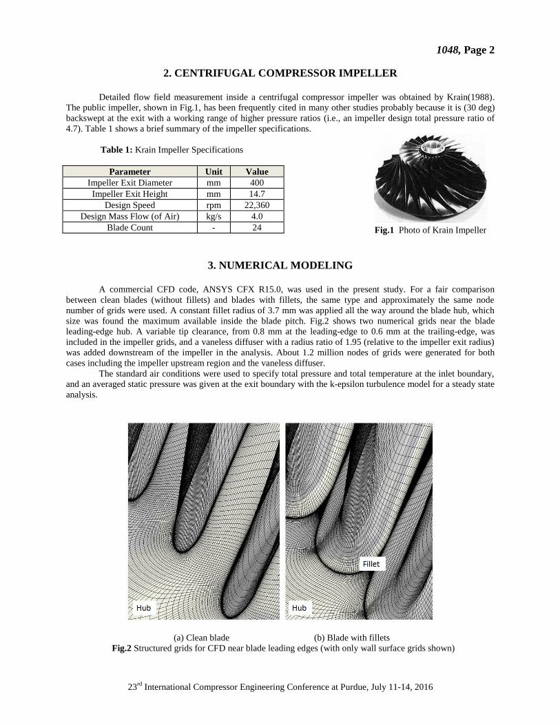
2. CENTRIFUGAL COMPRESSOR IMPELLER
Detailed flow field measurement inside a centrifugal compressor impeller was obtained by Krain(1988).
The public impeller, shown in Fig.1, has been frequently cited in many other studies probably because it is (30 deg)
backswept at the exit with a working range of higher pressure ratios (i.e., an impeller design total pressure ratio of
4.7). Table 1 shows a brief summary of the impeller specifications.
Table 1: Krain Impeller Specifications
Parameter Unit Value
Impeller Exit Diameter mm 400
Impeller Exit Height mm 14.7
Design Speed rpm 22,360
Design Mass Flow (of Air) kg/s 4.0
Blade Count - 24
3. NUMERICAL MODELING
A commercial CFD code, ANSYS CFX R15.0, was used in the present study. For a fair comparison
between clean blades (without fillets) and blades with fillets, the same type and approximately the same node
number of grids were used. A constant fillet radius of 3.7 mm was applied all the way around the blade hub, which
size was found the maximum available inside the blade pitch. Fig.2 shows two numerical grids near the blade
leading-edge hub. A variable tip clearance, from 0.8 mm at the leading-edge to 0.6 mm at the trailing-edge, was
included in the impeller grids, and a vaneless diffuser with a radius ratio of 1.95 (relative to the impeller exit radius)
was added downstream of the impeller in the analysis. About 1.2 million nodes of grids were generated for both
cases including the impeller upstream region and the vaneless diffuser.
The standard air conditions were used to specify total pressure and total temperature at the inlet boundary,
and an averaged static pressure was given at the exit boundary with the k-epsilon turbulence model for a steady state
analysis.
(a) Clean blade (b) Blade with fillets
Fig.2 Structured grids for CFD near blade leading edges (with only wall surface grids shown)
Fig.1 Photo of Krain Impeller
1048, Page 3
23rd
International Compressor Engineering Conference at Purdue, July 11-14, 2016
4. RESULTS AND DISCUSSION
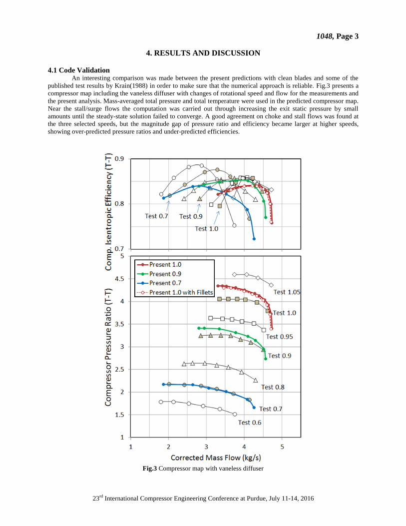
4.1 Code Validation An interesting comparison was made between the present predictions with clean blades and some of the
published test results by Krain(1988) in order to make sure that the numerical approach is reliable. Fig.3 presents a
compressor map including the vaneless diffuser with changes of rotational speed and flow for the measurements and
the present analysis. Mass-averaged total pressure and total temperature were used in the predicted compressor map.
Near the stall/surge flows the computation was carried out through increasing the exit static pressure by small
amounts until the steady-state solution failed to converge. A good agreement on choke and stall flows was found at
the three selected speeds, but the magnitude gap of pressure ratio and efficiency became larger at higher speeds,
showing over-predicted pressure ratios and under-predicted efficiencies.
Fig.3 Compressor map with vaneless diffuser

1048, Page 4
23rd
International Compressor Engineering Conference at Purdue, July 11-14, 2016
Fig.4 shows meridional velocity contours, normalized by the impeller tip speed, on two orthogonal sections
at design flow, which generally provide the development of secondary flow in the impeller passage. An impressive
agreement was observed on both planes, and especially at Section V, where very strong movements of secondary
flow normally happen, a reliable prediction was found with the pattern of the tip leakage vortex and the passage
vortex near the suction surface.
Fig.4 Normalized meridional velocity contours at design flow
4.2 Effects of Blade Hub Fillet
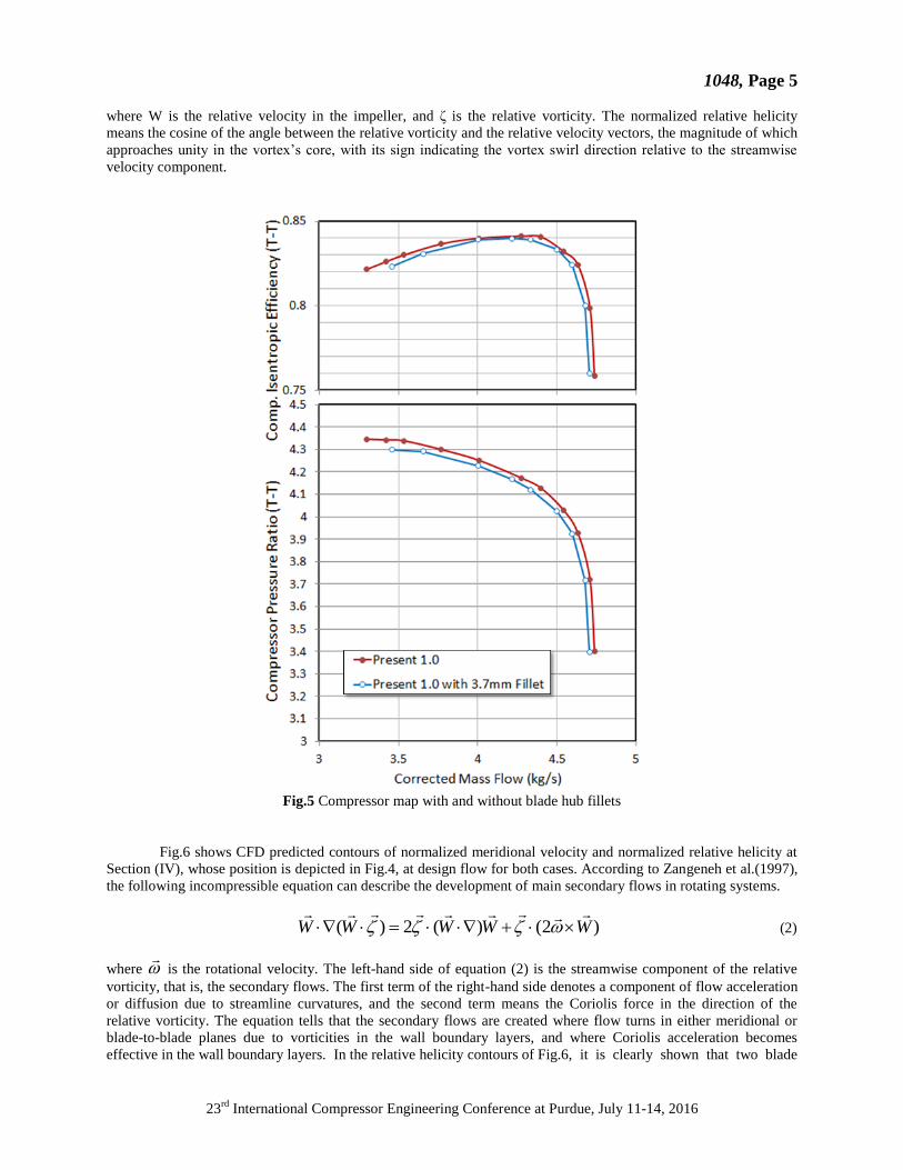
4.2.1 Overall Performance At design speed, the case with the 3.7 mm blade fillets on the hub was run from choke to stalled minimum
flow in the same manner, and the performance was plotted in Fig.3 together with the case with clean blades. A
zoomed-in version is given in Fig.5 where every aerodynamic performance, such as the choke margin, the range of
stable operation, the pressure ratio and the efficiency, clearly dropped relative to the case of clean blades without
fillets. The reduction of choke flow is of course predictable because of a smaller geometric area from fillets, but it is
of concern that both pressure ratio and efficiency were down over the range and even the compressor operability
was decreased. One finding, not too bad, is that the efficiency drop was minimized at design flow.
4.2.2 Secondary Flow Development By such a small change of the impeller geometry through blade fillets it was observed that overall
compressor performance was affected to some degrees that cannot be ignored, while blade fillets are still in most
cases neglected in the aerodynamic design process. Looking for backgrounds needs the investigation of the
secondary flow development inside the impeller passage which is generally related with the causes of losses. The
normalized relative helicity, Hn, is quite useful in understanding the vortex structure in the blade passage, which is
defined as,
W
WH n
(1)
1048, Page 5
23rd
International Compressor Engineering Conference at Purdue, July 11-14, 2016
where W is the relative velocity in the impeller, and ζ is the relative vorticity. The normalized relative helicity
means the cosine of the angle between the relative vorticity and the relative velocity vectors, the magnitude of which
approaches unity in the vortex’s core, with its sign indicating the vortex swirl direction relative to the streamwise
velocity component.
Fig.5 Compressor map with and without blade hub fillets
Fig.6 shows CFD predicted contours of normalized meridional velocity and normalized relative helicity at
Section (IV), whose position is depicted in Fig.4, at design flow for both cases. According to Zangeneh et al.(1997),
the following incompressible equation can describe the development of main secondary flows in rotating systems.
)2()(2)( WWWWW
(2)
where
is the rotational velocity. The left-hand side of equation (2) is the streamwise component of the relative
vorticity, that is, the secondary flows. The first term of the right-hand side denotes a component of flow acceleration
or diffusion due to streamline curvatures, and the second term means the Coriolis force in the direction of the
relative vorticity. The equation tells that the secondary flows are created where flow turns in either meridional or
blade-to-blade planes due to vorticities in the wall boundary layers, and where Coriolis acceleration becomes
effective in the wall boundary layers. In the relative helicity contours of Fig.6, it is clearly shown that two blade

1048, Page 6
23rd
International Compressor Engineering Conference at Purdue, July 11-14, 2016
Fig.6 Meridional velocity and relative helicity contours at Section (IV) at design flow
Fig.7 Meridional velocity and relative helicity contours at Section (V) at design flow

1048, Page 7
23rd
International Compressor Engineering Conference at Purdue, July 11-14, 2016
Fig.8 Meridional velocity and relative helicity contours at Section (VI) at design flow
vortices are developed along the suction and the pressure surface of the blade heading to the shroud, and another two
passage vortices are created near the hub and the shroud directing from the pressure surface toward the suction
surface. The counter-clockwise blade vortex near the suction surface is dominating, reinforced by the hub passage
vortex and the tip leakage vortex. The shroud passage vortex, augmented with blade loading and the Coriolis
passage vortex, is pushed down by the tip leakage vortex. In the meridional velocity contour, a large low-momentum
area is formed near the shroud which is caused by the spreading-out tip leakage vortex interacting with other
secondary flow vortices. In the case with blade fillets, compared with the case of clean blades, a local flow
acceleration is found at the corner of the hub pressure surface, caused by the fillet, and another increase of the
meridional velocity is seen near the suction surface. Such a local acceleration can be also confirmed from a small
scraping vortex, formed at the corner with a counter-clockwise rotation in the clean blades, which is however
removed with blade fillets.
At Section (V), Fig.7, the shroud passage vortex, growing supported by blade loadings, the Coriolis vortex
and the blade vortex near the pressure surface, starts to occupy most area of the section with a clockwise rotation. Its
core is filled with the accumulated low-momentum fluid which becomes a main source of losses. The blade vortex
near the suction surface, carrying the high-momentum fluid, is pushed toward the hub, but the tip leakage vortex still
stays near the shroud. The scraping vortex at the corner of the hub pressure surface in the clean blades is growing,
however, it is obviously suppressed with blade fillets by the local flow acceleration. In the case with blade fillets, as
a result of different balancing forces acting in the passage, the extended shroud passage vortex is observed with a
higher core than the case of clean blades, which means more wake flows.
At the impeller exit, Section (VI) of Fig.8, the shroud passage vortex covers most part of the section, while the high-
momentum fluid region becomes confined near the hub toward the pressure surface corner. Due to an interaction of
passage vortices with the strong tip leakage vortex, the wake is positioned apart from, the so-called, near shroud
suction surface. In the case with blade fillets, the core strength of the extended shroud passage vortex is still slightly
higher than the case of clean blades. Another local flow acceleration is seen near the shroud suction surface in
addition to that at the corner of the hub pressure surface from the meridional velocity contours.
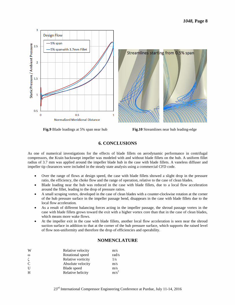
The local flow acceleration around the hub blade fillet can be visualized through blade loadings and
streamline plots, as shown in Fig.9 and Fig.10. Such a reduction of blade loadings at 5% span near the hub
contributes to the drop of pressure ratios, while the increased core strength of the shroud passage vortex, already
observed in Fig.7 and Fig.8, would lead to the drop of compressor efficiency and operability, found in Fig.5.
1048, Page 8
23rd
International Compressor Engineering Conference at Purdue, July 11-14, 2016
Fig.9 Blade loadings at 5% span near hub Fig.10 Streamlines near hub leading-edge
6. CONCLUSIONS
As one of numerical investigations for the effects of blade fillets on aerodynamic performance in centrifugal
compressors, the Krain backswept impeller was modeled with and without blade fillets on the hub. A uniform fillet
radius of 3.7 mm was applied around the impeller blade hub in the case with blade fillets. A vaneless diffuser and
impeller tip clearances were included in the steady state analysis using a commercial CFD code.
Over the range of flows at design speed, the case with blade fillets showed a slight drop in the pressure
ratio, the efficiency, the choke flow and the range of operation, relative to the case of clean blades.
Blade loading near the hub was reduced in the case with blade fillets, due to a local flow acceleration
around the fillet, leading to the drop of pressure ratios.
A small scraping vortex, developed in the case of clean blades with a counter-clockwise rotation at the corner
of the hub pressure surface in the impeller passage bend, disappears in the case with blade fillets due to the
local flow acceleration.
As a result of different balancing forces acting in the impeller passage, the shroud passage vortex in the
case with blade fillets grows toward the exit with a higher vortex core than that in the case of clean blades,
which means more wake flows.
At the impeller exit in the case with blade fillets, another local flow acceleration is seen near the shroud
suction surface in addition to that at the corner of the hub pressure surface, which supports the raised level
of flow non-uniformity and therefore the drop of efficiencies and operability.
NOMENCLATURE
W Relative velocity m/s
ω Rotational speed rad/s
ζ Relative vorticity 1/s
C Absolute velocity m/s
U Blade speed m/s
H Relative helicity m/s2

1048, Page 9
23rd
International Compressor Engineering Conference at Purdue, July 11-14, 2016
Subscript
2 Impeller exit
m Meridional component
n Normalized
REFERENCES
Calvert, W.J. et al., 1999, Transonic Fan and Compressor Design, Proceedings of the Institution of Mechanical
Engineers, Part C: Journal of Mechanical Engineering Science, Vol.213, pp.419-436
Curlett, B.P., 1991, The Aerodyanmic Effects of Fillet Radius in a Low Speed Compressor Cascade, NASA TM-
105347
Hoeger, M. et al., 2006, Impact of a Fillet on Diffusing Endwall Flow Structure, ISROMAC 2006-057
Krain, H., 1988, Swirling Impeller Flow, ASME Journal of Turbomachinery, Vol.110, pp.122-128
Kuegeler, E. et al., 2008, Influence of Blade Fillets on the Performance of a 15 Stage Gas Turbine Compressor,
ASME GT2008-50748
Syka, T. et al., 2015, Hub and Shroud Fillets Influence on the Radial Compressor Stage Efficiency, EPJ Web of
Conference 92, 02090
Zangeneh, M. et al., 1997, On the Design Criteria for Suppression of Secondary Flows in Centrifugal and Mixed
Flow Impellers, ASME Paper 97-GT-393
ACKNOWLEDGEMENT
The author gratefully acknowledges the support of Danfoss Turbocor for the present study and its publication.