Embed Size (px)
Citation preview

1
Spring 2020 - CIV E495
James Haughey
San Diego State University
5/6/2020
100% Civil Creations Inc. Design Submittal for: Coronado
NAB Pedestrian Tunnel
Prepared for: City of Coronado
Prepared by: Civil Creations Inc.
San Diego, CA
Civil Creations Inc. Team 22
Project Manager: Mina Ghareeb
Aya Alaboosi, Lara Al Isso, Ayat Alobaidi
Hani Noori, Mustafa Rasheed

Table of Contents
1. Executive Summary …….……………………………………………….…..….1
1.1 Vicinity Map ……………………………………………….…….………..…....3
2. Project Background, Need and Purpose…………………..……………….......3
2.1 Scope of Work ………………………………..…………….……………….......3
2.2 Project Background ……………………………………….………….…….…..4
2.3 Existing Site Conditions …………………………………….………..……..….4
3. Basis of Design …………………………………………….………...............….5
4. References ……………………………………………………………….…..….6
5. List of Appendices
Appendix 1: Geotechnical Study….…………………………………………..……….8
Appendix 2: Storm Water Study………………………………………….…………..24
Appendix 3: Traffic Control Study… ………………………………………………..34
Appendix 4: Structural Design ……………………………………………….............47
Appendix 5: Construction Management ……………………………………..……...69
6. Cost Estimate …………………………………………………………….…..100
7. Project Schedule ………………………………………………………...........101
8. Construction Schedule …………………………………………………....….102
9. Plans Set ………………………………………………………………..…..…103

1
1. Executive Summary
Naval Base Coronado is located at Coronado, California. It’s one of the most unique
and beautiful beachfront cities in the world. By measuring only 13.5 square miles and
located just minutes from downtown Dan Diego. This enchanted island has it all:
beaches, parks, numerous recreational activities, highly rated schools, top notch
municipal services, a wonderful climate and an ideal location. The Naval Amphibious
Base (NAB), Coronado was established in 1943. NAB is the home to over 30 tenant
commands with a population of approximately 5,000 personnel, including major
commands. In the present state, the City of Coronado has decided to build a pedestrian
tunnel connecting NAB East Gate and the West Gate. The current pedestrian crossing
at Caltrans SR-75 and Tarawa Road is coordinated with automobile traffic and presents
a safety hazard for pedestrians. The City of Coronado would therefore like to replace
the current at-grade foot crossing with a secure, pedestrian-friendly tunnel under SR-75.
The purpose of a pedestrian tunnel is to improve safety, accessibility, and faster
connectivity.
Naval Amphibious Base Coronado (NAB Coronado) is a naval installation located in
Coronado, California. The base, situated on the Silver Strand, between San Diego Bay
and the Pacific Ocean, is a major Navy shore command, supporting over 30 tenant
commands, and is the West Coast focal point for special and expeditionary warfare
training and operations. The on‑base population is 5,000 military personnel and 7,000
students and reservists. The base is one of the eight components of Naval Base
Coronado (NBC). The City of Coronado has decided that it is the time to replace the
existing at-grade pedestrian crossing with a safe pedestrian-friendly tunnel under SR-75
to connect between the two gates due to a significant safety hazard for pedestrians
between Caltrans SR-75 at the existing traffic signal at Tarawa Road. This existing
pedestrian crossing is synchronized with vehicular crossing traffic.
The principal outcomes of this project are to assure safety for the pedestrians by
presenting value-oriented, client-focused services equipped with a clear understanding
of laws, codes and current practices. Our goal is client satisfaction achieved by ensuring

2
that we understand the Clients’ needs, wants, and concerns while providing work that is
accurate, complete on schedule and within budget. It also provides all the labor and
materials required to carry out assessments and construction services including civil,
site, structural, geotechnical and communications work for existing tunnel to support the
facilities project.
The team looks out for the interests of the owner. Civil Creations Inc. uses a competition
in the selection of the trades to improve the efficiency and quality for owner. Taking into
consideration, there are possibilities of risks that will occur in the future, Civil Creations
Inc. has done well in considering such risks. For mobilization and access, the workers
have considered the layout of where the materials are placed and rerouting the paths
the machinery will be operated on site. For equipment and material delay due to COVID
-19, Civil Creations Inc. has considered the types of equipment will be used for this
project along with the use of two trucks haul for both sides to increase efficiency and
production operation. To ensure the accuracy of schedule and to finish on time, the
team will conduct a weekly meeting with all trades and will send a schedule monthly
updates to the owner to ensure that everyone on track with the baseline schedule and
can pre-plan any activities or deliveries.
The goal for the Civil Creations Inc. is working proficiency, and accurately by designing
and working with the City of Coronado to approach the needs for this project Coronado
NAB Pedestrian Tunnel. Safety for the pedestrian is our priority; this project is to assure
safety and accessibility to pedestrian. As a result, the bus stop will be temporary
relocated to Rendova Road. A Boring Machine (TBM) that weight 30 tons will be used
after the excavation of 22 ft. Due to the Global issue for what is happening and it is a
hardly effecting the global economic and the US specific, the Civil Creations INC trying
to make the total cost estimate because of COVID-19, the total cost estimate for this
project is $3,138,390.00 This is considered a competitive. The commencement date for
this project is 6th of July 2020 and the competition date is 16th of January 2023.

3
1.1 Vicinity Map
Figure 1: Vicinity Map
2. Project Background, Need and Purpose
2.1 Scope of Work
This project is in replacement of the pedestrian cross Caltrans SR-75 at the existing
traffic signal at Tarawa Road with the existing at-grade pedestrian crossing with a safe
pedestrian-friendly tunnel under SR-75. This pedestrian tunnel is to connect both sides
of NAB under CaltransSR-75 to assure safety for the pedestrians
To fulfil City of Coronado, Civil Creations Inc. will perform the following work:
1. Provide site survey and inspection of existing
2. Design engineering documents and provide construction drawings
3. Structural design of the tunnel
4. Provide Civil site designs
5. Provide Geotechnical studies with the type of soil with recommendations
6. Storm water studies

4
7. Providing a detail Cost estimate
8. Provide traffic control studies
2.2 Project Background
Naval Amphibious Base Coronado (NAB Coronado) is a naval installation located in
Coronado, California. The base, situated on the Silver Strand, between San Diego Bay
and the Pacific Ocean, is a major Navy shore command, supporting over 30 tenant
commands, and is the West Coast focal point for special and expeditionary warfare
training and operations. The on‑base population is 5,000 military personnel and 7,000
students and reservists. The base is one of the eight components of Naval Base
Coronado (NBC). The City of Coronado has decided that it is the time to replace the
existing at-grade pedestrian crossing with a safe pedestrian-friendly tunnel under SR-75
to connect between the two gates due to a significant safety hazard for pedestrians
between Caltrans SR-75 at the existing traffic signal at Tarawa Road. This existing
pedestrian crossing is synchronized with vehicular crossing traffic.
2.3 Existing Site Conditions
On the day of the visit, there was sewer drainage by the traffic light next to the east gate of the
NAB. On the east side of SR 75, some trees and bushes will need to be removed in order to build
the access ramp and stairs.
Silver Strand Boulevard is the only major corridor adjacent to NAB that military personnel can
use to leave the facility to access the cities of Coronado and Imperial Beach and other major
arterials and freeways. MTS Route 901 is the only bus route that provides transit service to and
from NAB. This route has a bus stop outside of Gate 7 along Silver Strand Boulevard and needs
to be relocated for construction activities. The proposed tunnel location will connect the east and
west side of Tarawa Rd as it will be explained later in the report.

5
3. Basis of Design
This Pedestrian Tunnel to be 10 ft deep and 20 ft width walkway. The 20 ft consists of
10 feet of 5 feet upstairs, 5 ft downstairs, and 10 feet for disabled people. We are
assuming that there should be a removal of existing sidewalk, existing concrete, existing
trees. This tunnel should have access for pedestrians and people with disabilities. That
means, ADA requirements should be adhered to, and further honed to make access
leisurely and amenable to all involved. The TBM boring machine will be used for the
boring process. The core structure will be steel and reinforced concrete to maintain
more than enough strength for pedestrian use. Allowances for maintenance access, and
public safety barriers will be made.
Civil Creations Inc. will prepare for the City of Coronado, Caltrans, Navy, State, and
Federal Permits, the Structural design of the new tunnel, and providing detailed Cost
Estimation at Submittal, which is discussed in the report.
Furthermore, our assumed tunnel will allow the pedestrian to traverse without waiting for
a whole pedestrian cycle of traffic light. Another advantage of the road tunnel system is
that its use will lead to a sharp decrease in the time spent in a motor vehicle, resulting in
a reduction in traffic congestion.

6
4. List of References
Climate Coronado - California. (2020). Retrieved March 5, 2020
“Industrial Gantry Crane for Tunnel, Subway, & Metro Use.” Dongqi Crane, 22 Nov. 2011
Ninyo & Moore, 2008, Proposal for Geotechnical Design Evaluation, Planned Boat House Club
room, Glorietta Bay Park, Coronado, California, dated November 26
"Roadheaders for Tunneling, Excavation, and More." Antraquip Corporation | Roadheaders &
Hydraulic Cutters | Rock Grinders, Concrete Cutters, 2020
Sinoart. "Gantry Crane for Tunnel Boring Machine." Gantry Crane, Container Gantry Crane,
Project Crane, 2017
Weston Solutions, and San Diego State Geography Department. “Learn about the San Diego
Bay Watersheds.” San Diego Bay Watersheds Common Ground- Learn About the
Watersheds, 2018
Souder, Chris. Temporary Structure Design. John Wiley & Sons, 2015
Hamada, T., Sugawara, K., Tanaka, K., & Kanai, M. (2017). U.S. Patent No. 9,672,743.
Washington, DC: U.S. Patent and Trademark Office.
He, S., Salem, O., & Salman, B. (2017, January). An asset management framework for
ramp metering system and adaptive traffic control systems. In 9th International
Structural Engineering and Construction Conference: Resilient Structures and
Sustainable Construction, ISEC 2017. ISEC Press.
Kanai, M., Katou, M., & Hamada, T. (2019). U.S. Patent No. 10,446,036. Washington,
DC: U.S. Patent and Trademark Office.
Lu, M., & Zhao, T. (2018). Impact Analysis of Temporary Traffic Control Design in
Planning Construction for Transportation Infrastructure Expansion: the
Contractor’s Perspective (No. 18-03438).

7
Ram, P., & Smith, K. (2017). Traffic Control Strategies for Concrete Pavement
Rehabilitation and Reconstruction (No. FHWA-HIF-17-007).
Saha, T., & Sisiopiku, V. P. (2020). Assessing Work Zone Traffic Control Options for 3-
to-1 Lane Closures. Journal of Transportation Technologies, 10(01), 50.
Zhang, F., & Gambatese, J. A. (2017). Highway construction work-zone safety:
Effectiveness of traffic-control devices. Practice Periodical on Structural Design
and Construction, 22(4), 04017010.
Biomassone-how-much-material. April 17,2017.
RSMeans data is North America's leading construction estimating database. Nov 11,2019
Codes:
a) American Concrete Institute (ACI) and American Institute of Steel Construction (AISC) Manuals.
b) American Association of State Highway and Transportation Officials (AASHTO) Standard
Specifications.
c) Federal Highway Administration Load and Resistance Factor Design for
Highway Bridge Superstructures (LRFD)
d) Golder Associates and James F. Maclaren Ltd., 1976, Tunneling Technology: An Appraisal of the
State of the Art for Application to Transit Systems.
e) The American Society for Testing and Material Standards (ASTM)
f) Technical Manual for Design and Construction of Road Tunnels.

8
Appendix 1: Geotechnical Study Report
Coronado NAB Pedestrian Tunnel
Final Design Submittal by Civil Creations Inc.
Team 22
May 6th, 2020

9
Table of Contents
Appendix 1: Geotechnical Study
1.1 Soil Classification Study and Soil Layer Analysis…………………..10
1.1.2 Groundwater………………………………………………………...12
1.2 Underground Tunnel Structural Design Requirements……………13
1.3 Tunnel Foundation Lateral Resistance……………………………...13
1.4 Development Analysis………………………………………………...13
1.5 Development Constraints………………………………………….....14
1.6 Soil Bearing Capacity……………………………………………..….15
1.7 Geologic Hazards……………………………………………………..15
1.7.1 Faulting and Seismicity………………………………………….…15
1.7.2 Ground Surface Rupture…………………………………………..15
1.7.3 Ground Shaking…………………………………………………….16
1.7.4 Liquefaction and Seismically Induced Settlement…………….….16
1.7.5 Lateral Spreading……………………………………………….…16
1.8 Tunnel Structural Fill Material and Fill Compaction……………...16
1.9 Foundation Recommendations………………………………………17
1.10 Tunnel Wall Drainage………………………………………………17
1.11 Seismic Wall Design…………………………………………………18
1.12 Tunnel Bedding……………………………………………………...20
1.13 Tunnel Grading……………………………………………………...20
1.14 Recommendations…………………………………………………...21
1.15 Calculations………………………………………………………….22
List of Figures
Figure 1.2 : Boring Data………………………………………………....11
Figure 1.3: Boring Data………………………………………………….12
Figure 1.4: Polyethylene Drainage Location…………………………...18
Figure 1.5: Soil Pressure Diagram……………………………………...26
List of Tables
Table 1.1: Soil Classification……………………………………………10
Table 1.2: Seismic Factors………………………………………………19

10
1.1Soil Classification Study and Soil Layer Analysis
Soil samples were available through Ninyo & Moore to Civil creations Inc. and a geotechnical
evaluation was conducted. According to Ninyo & Moore, several tests were made that included
dry density and moisture content, sieve analysis, swell-consolidation, and water-soluble sulfate
content tests. To assess possible heaves, the swell test tests were wetted at different applied
weights, which provided the overburden pressure approximates. During the investigations, at
around 3 to 7 feet thick there was a layer an existing, was experienced at the ground surface in
the two borings. The brown and dark gray damp to saturated, loose to medium dense, poorly-
graded sand with silt, silty sand, and sandy silt was the composition of fill as shown in Table 1
(Ninyo and Moore, 2008).
Table 1: Soil Classification
Brown, damp to moist, medium dense silty, scattered shell fragment sand was experienced
underneath the current fill in the boring TH-1 at 10 feet below the existing ground. The earth was
moist to wet dependent on field infiltration obstruction tests. Two examples of the mud tried in
our research center displayed low estimated swell estimations of 0.1 and 0.2 percent when wetted
under-evaluated overburden pressure. Dark gray, saturated, loose, silty fine sand was discovered
at around 16 feet under the fill layer using the boring TH-2. Dark gray, saturated, dense, poorly

11
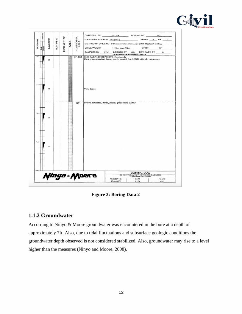
graded fine sand with silt, micaceous was found at 25.3 ft. depth as shown in Figure 2 and
Figure 3.
Figure 2: Boring Data 1
12
Figure 3: Boring Data 2
1.1.2 Groundwater
According to Ninyo & Moore groundwater was encountered in the bore at a depth of
approximately 7ft. Also, due to tidal fluctuations and subsurface geologic conditions the
groundwater depth observed is not considered stabilized. Also, groundwater may rise to a level
higher than the measures (Ninyo and Moore, 2008).

13
1.2 Underground Tunnel Structural Design Requirements/Concrete
Requirements
The measured soluble sulfate concentration in one sample from the site at less than 0.1 percent.
Concentrations of Sulfate that are below 0.1% indicate Class 0 exposure to attacks by sulfates for
concrete coming in contact with the subsoil, based on the ACI 201.2R-01, provided by the
2008 American Concrete Institute (ACI) Manual of Concrete Practice (American Concrete
Institute, 2008). Having such levels of concentrations of sulfate, the Type I/II cement is
recommended by ACI for use for concrete that is likely to get in contact with the underlying
subsoil. Based on construction experience, there may be instances of superficial damage
occurring to the exposed surfaces made of highly permeable concrete, even though sulfate levels
may be considerably at lower levels.
1.3 Tunnel Foundation Lateral Resistance
The foundation resistance to horizontal loads, it is suggested a permissible passive weight
applied by a proportionate water pressure load of 300 pounds for each cubic foot should be
utilized. This worth accept that the ground is level for a separation of 10 feet or more, or multiple
times the stature producing the passive weight, whichever is more noteworthy. It is prescribed
that the upper I foot of soil not secured by asphalt or a solid section be dismissed while
computing the resistance. The frictional resistance from lateral loads, a coefficient of contact of
0.35 is recommended for utilization among soil and cement. On the off chance that detached and
frictional protections are to be utilized in the mix, we suggest that the inactive worth not surpass
one-portion of the absolute obstruction. However, the resistance loads provided might be
expanded by 33% when factoring in short duration loads like the wind or seismic loads (Marinos,
2019). The soil pressure will dictate the load requirements in terms of tunnel sizes and concrete
reinforcements.
1.4 Development Analysis
Underground pedestrian tunnels have been in use for years in various cities. Separating
pedestrian and vehicle traffic, to shield pedestrians from inclement weather and add a new level
of retailing to encourage downtown development has been done in many large cities.
Underground pedestrian systems function as a medium by linking transport, working and leisure

14
places together in integrated spaces with a variety of functions to create an urban synergy.
Adopting a systems approach to analyzing urban pedestrian space helps to conceptualize the
relationship between underground pedestrian systems and other pedestrian spaces within the
broader urban environment Cui, 2015).
In general, there are three main benefits of developing an underground pedestrian tunnel link in
Coronado California. Firstly, viewing the city as a complex system, an underground pedestrian
system is a vital subsystem of public space systems, expanding space and movement below the
surface pedestrian systems. Secondly, an underground pedestrian system uses walking as a mode
of transport to link and aggregate activities such as retailing and mass transit within an
underground setting. Thirdly, an underground pedestrian system has an important functional
feature through the provision of underground public passageways functioning as a medium that
integrates ground level spaces with underground spaces (Cui, 2015).
1.5 Development Constraints
All underground excavations during tunnel constructions cause pressure redistribution in the
ground, which prompts ground misshaping. Moderating the related hazard is a basic factor
during the tunnel plan procedure. Albeit different decisions can be made during the plan
procedure to lessen the danger of harm to contiguous structures, instrumentation checking of
existing structures is a basic piece of the development procedure to give a quantitative evaluation
of the burrowing activity and choose development technology. The gathered field estimations
can likewise be utilized to refine the plan findings and change development systems if
fundamental (Vakili, 2019).
Ground deformation observation is critical for shallow urban tunnel development with a slurry
or earth pressure balance shield. Experimental conditions and numerical displaying, with
examinations guided by point of reference ventures, are ordinarily utilized at the structure stage
to evaluate the ground development due to burrowing and for deciding suitable TBM face
pressures. During development, gathered information on ground change is surveyed against
anticipated qualities. This may bring about recently performed investigations being changed and
TBM task parameters being balanced. Gathered ground-change information can likewise be
useful for any passage venture that may be built later on (Baker, 2019).
15
1.6 Soil Bearing Capacity
The construction site is characterized by brown and dark gray damp to saturated, loose to
medium dense, poorly-graded sand with silt, silty sand, and sandy silt was the composition of the
fill. An allowable bearing pressure of 2,000 pounds per square foot (psi) is recommended for use
in foundations constructed on this fill. The allowable bearing capacity can be increased by one-
third when considering loads of short duration such as wind or seismic forces. A design
coefficient of subgrade reaction, of 120 pounds per cubic inch may be used for evaluating
deflections at the subject sites.
1.7 Geologic Hazards
Coronado California is a seismically active therefore seismic hazard such as ground rapture and
shaking resulting from seismic activity, liquefaction, lateral spreading, and dynamic settlements
were considered during this project.
1.7.1 Faulting and Seismicity
The site falls under the seismic active Zone 4 but the review of the past geological maps and
literature reveals that the site is not subject to any active or potentially active faults as there is no
evidence pointing at ground movement over the past 11,000 years or 11,000-2,000,000 years
respectively. This site falls out of the State of California Alquist-Priolo Special Studies Zone for
faults resulting from an earthquake. The seismic event of great significance on this tunnel
construction is the magnitude 7.2 earthquake on the Rose Canyon fault that is located about one
mile to the northeast of the tunnel construction site.
1.7.2 Ground Surface Rupture
The damage on the tunnel due is low as there is no evidence of active faults around the site.
There are possibilities of damages like cracking due to shaking from far vents, but this remains
an insignificant seismic hazard to the tunnel.

16
1.7.3 Ground Shaking
Analysis by Ninyo & Moore on the project site estimates a modified Design Earthquake (PGADE)
of 0.62g based on the United States Geological Survey and the web-based ground motion
calculators and the design earthquake for the site to be 0.41g. The estimations were based on the
recommendations by California Building Code-2007 which requires structural designs to be
based on the maximum ground acceleration of a 2% probability of exceedance in fifty years, that
is, the Maximum Considered Earthquake.
1.7.4 Liquefaction and Seismically Induced Settlement
Analysis of the liquefaction potential based on the modified GADE and assumed granular
subsurface soils lying below the highest groundwater table, revealed a liquefaction potential of
up to 19 feet deep below the existing grades. It was therefore estimated that a dynamic settlement
of about 4 inches is possible due to seismic events occurring in the site vicinity. In general 2
inches, differential dynamic settlement can be expected over a depth of 40 feet in the
construction site (Ninyo and Moore, 2008).
1.7.5 Lateral Spreading
Studies associate lateral spreading with occurrence in the free face direction typically the
retaining wall, channel or slope but minimum in the gently sloping grounds. The distance of the
construction site from the epicenter of an earthquake and the liquefiable layer thickness also
contribute factors of lateral spreading. This site is subject to effects of nearby earthquake events,
has a considerably high thickness of liquefiable layers and its distance to Glorietta Bay, a free
face, there exists the potential for lateral spreading at the tunnel construction site.
1.8 Tunnel Structural Fill Material and Fill Compaction
Fill material should not contain rocks or lumps over approximately 4 inches in diameter, and not
more than approximately 30 percent larger than a quarter inch. Utility trench backfill material
should not contain rocks or lumps over approximately 3 inches in general. Imported fill material
should generally be granular soils with a very low to low expansion potential and non-corrosive.

17
Before placement of compacted fill, the ex-posed ground surface should be scarified, moisture
conditioned as needed to achieve moisture contents generally above the optimum moisture
content, and then compacted to relative compaction of 90 percent as evaluated per ASTM D
1557 (ASTM, 2012).
1.9 Foundation Recommendations
Civil Creation Inc. recommend the use of continuous footings founded on compacted fill. The
continuous footing supports the tunnel walls bearing on re-compacted fill and may be designed
using an allowable bearing capacity of 2,000 psi. This allowable bearing capacity may be
increased by one-third when considering loads of short duration such as wind or seismic forces.
The continuous footings should have a width of 15 inches and should be reinforced following the
recommendations of the project structural engineer.
Also, an allowable passive pressure exerted by an equivalent fluid weight of 300 pounds per
cubic foot be used for the resistance of foundations to lateral loads. This value assumes that the
ground is horizontal for a distance of 10 feet or more, or three times the height generating the
passive pressure, whichever is greater.
1.10 Tunnel Wall Drainage
This underground tunnel will utilize the conventional wall or surface drainage method. This
method uses large foamed polythene mats that are mounted on steel rods placed at adequate
distances in the wall of the tunnel. Water leaking from the tunnel walls drips on the polythene
mat, running down along the wall drains to the drainage channels at the bottom of the tunnel.
The polyethylene mat is then covered with shot-concrete due to its sensitivity to mechanical
damage and susceptible to fire to its high flammability. The drainage mats are used to assemble
and fixe on the threaded rods using different steel materials. Finally, the polyethylene drainage
mat was covered with two layers the first being a 60 mm thick shot-concrete layer reinforced
with steel polypropylene fibers and followed with another 20mm thick layer of concrete mixed
polypropylene fibers as shown in Figure 4.

18
Figure 4: Polyethylene Drainage Mat Location
1.11 Seismic Wall Design
Coronado California corresponds to Seismic Zone 4, therefore, the Seismic Design Parameters
for the design of the tunnel wall was according to the design for structures located in Seismic
Zone 4 and the appropriate American design standards. The seismic design parameters
corresponding to the site are provided by California Building Codes and mapped spectral
acceleration parameters based the United States Geological Survey. Table 2 provides the various
seismic factors for consideration in the tunnel wall design.

19
Factors Values
Site Class D
Site Coefficient, Fa 1.000
Site Coefficient, Fv 1.500
Mapped Short Period Spectral Acceleration, Ss 1.552g
Mapped One-Second Period Spectral Acceleration, S1 0.616g
Short Period Spectral Acceleration Adjusted Fr Site Class, SMS 1.552g
One-Second Period Spectral Acceleration adjusted For Class, SM1 0.924g
Design Short Period Spectral Acceleration, SDS 1.035g
Design One-Second Period Spectral Acceleration, SD1 0.616g
Table 2: Seismic Factors

20
1.12 Tunnel Bedding
Civil Creation Inc. will excavate up to 22 feet outwards from the continuous footing or to the
point that is practically fit. The on-site earth materials were suitable for use as bedding backfill
so long, they are free from organic material, debris, clay clumps and rocks having a diameter
greater than 3 inches. Backfill must be compacted to relative compaction of 90 percent except for
the upper 12 inches of the backfill that are compacted to relative compaction of 95 percent as
evaluated by ASTM D 1557. Also, the backfill materials or beddings must conform to the
requirements for structural backfill by the Standard Specifications for Public Works. soils that
are present on top of tunnel are primarily fine aggregates, soils below tunnel are coarse grain
soils including the bedrock.
1.13 Tunnel Grading
According to an analysis by Ninyo & Moore, the existing fill materials were considered
compressible and not suitable for structural support in their present condition. The existing fill
materials must be removed to a depth of approximately 22 feet below the existing grade. Placing
gravel and stabilization geo-fabric at the bottom of the resulting excavations to stabilize the
removal bottoms before receiving fill is recommended, with the resulting removal surface should
then be scarified approximately 8 inches, moisture conditioned to near the recommended
optimum moisture content
The tunnel grading is important for the safety and comfort of the users including pedestrians on
foot and cyclists utilizing the channel as a separate grade for safety during road crossing. A
maximum grade of 3.5% is recommended for tunnels utilized by motorists for maximum safety.
However, for tunnels limited to cyclists and pedestrians a maximum grade of 5% is
recommended. Therefore, a grade of 3.5% should be maintained during the remedial grading
process, involving the removal of existing fills and replacements with appropriate fill and
subsequent compactions.
21
1.14 Recommendations
This report finds no significant geotechnical condition that can stop the implementation of the
project in terms of stability and safety provided that the recommendations are incorporated in the
design of the tunnel. Generally, the following conclusions were made:
● The construction site is characterized by brown and dark gray damp to
saturated, loose to medium dense, poorly-graded sand with silt, silty sand, and
sandy silt was the composition of the fill.
● Groundwater exists at a depth of approximately 7feet but is subject to
fluctuations due to tidal fluctuations and subsurface geologic conditions.
● The existing fill materials in the site are not suitable and should be excavated
out to at least 22 feet below existing ground levels. The excavations can, however,
be done up to designed levels in consideration of other factors.
● The excavated soils from the site are suitable for re-use as fill materials so long
as the requirements for fill compactions are met.
● An allowable soil bearing pressure of 2,000 pounds per square foot (psi) is
recommended for use in foundation design and constructed on the fill.
● The tunnel construction site is in the vicinity of the magnitude 7.2 earthquake
on the Rose Canyon fault therefore strong seismic designs must be considered in
the design.
● The site is subject to liquefaction and seismically induced settlement. A
dynamic settlement of about 4 inches is estimated due to seismic events occurring
in the site vicinity with 2 inches differential dynamic settlement in every 40 feet
depth. Therefore, possibilities of surface cracking and ground rupture.

22
1.15 Calculations
Based on the soil classification chart, sandy with silt is a coarse- grained soils, void ratio(e) for
sandy clay soil= 0.55
Volume of Solids (Vs)=11+e=11+0.55= 0.645= 64.5% of sample is voids
Weight of Solids=γwater x S.G x Vs
Weight of Solids=62.4 pcf x 3.5 x 0.645= 140.87 Pcf
Submerged Unit Weight=Ws - ( γwater x Vs)
Submerged Unit Weight=140.87 pcf- ( 62.4 pcf x 0.645)= 100.62 Psf
Foundation Calculations:
A- 16ft *10ft *0.833ft =133 ft^3🡺 4.92 yd^3 B- 108ft*20ft*0.833ft=1799 ft^3🡺 66.6 yd^3 C- 70ft* 10ft*0.833ft=583ft^3🡺 21.6 yd^3
Foundation Total= 94 yd^3
Grading and Soil Compaction Calculations:
A- 16ft*10ft*0.67=107.2ft^3🡺 3.97yd^3 B- 108ft*20ft*0.67ft=1447ft^3🡺 53.6yd^3 C- 70ft*10ft*0.67ft=569ft^3🡺 21.1yd^3
Grading and Soil Compaction Total= 78.67yd^3
In order to support the active soil pressure, Shoring design falls into this category because the
purpose is to support the excavation or trench with adequate support that resist collapse and
minimizes deflections and settlement as shown in Figure 5.
The value of active soil pressure coefficient should always be less than 1.000. Cohesion (Φ)= 25°. C= 275.
Ka=1- sinΦ1+ sin Φ=1- sin 251+ sin 25= 0.41

23
When soil is loading a structure, the pressure develops at a depth of 22 ft.
P= γ x h x Ka- 2 x c x (square root Ka)
P Top= 100.62 pcf x 0 x 0.41- 2 x 275 x (square root(0.41))= -352.17 psf
P bottom= 100.62 pcf x 22 ft x 0.41- 2 x 275 x (square root(0.41))= 555.42 psf
Figure 5: Soil Pressure Diagram

24
Appendix 2: Storm Water Study Report
Coronado NAB Pedestrian Tunnel
Final Design Submittal by Civil Creations Inc.
Team 22
May 6th, 2020

25
Table of Contents
Appendix 2: Stormwater Study
2.1 Storm Water Study………………………………………………………......28
2.2 Drainage Study……………………………………………………………....29
2.3 Runoff Calculations……………………………………………………….....30
2.4 Existing Basin Calculation………………………………………………......32
2.5 Proposed Basin Calculation………………………………………………....33
2.6 Water Reuse and Recommendations……………………………………….34
2.7 Techniques for Reducing Storm Flows……………………………………..34
2.8 Scope of Work………………………………………………………………..35
List of Figures:
Figure 2.6: Land Use Percentage……………………………………………....28
Figure 2.7: Basin Location……………………………………………………...29
List of Tables:
Table 2.3: Hydrology Soil Group D…………………………………………….30

26
2.1 Storm Water Study
According to San Diego Basin Water Quality Control Plan (Manual 1994), Coronado island is
part of the Otay River watershed (HUI 910.0) and covers approximately 160 square miles in
southwest San Diego County and is one of the three watersheds that discharge to San Diego Bay
(sdbay). “As shown in Figure 6, the land use in the watershed is primarily Undeveloped
(39.8%), Residential (20.2%), and parks and recreation (24.6%). There is approximately 24.9%
impervious surface” (Sdbay). The rainfall intensity in Coronado island is 9.4in/year
(usclimatedata). In Figure 7, we have two inlets in our project site, and it is connected to the
basin.
Figure 6: Land Use Percentage

27
Figure 7: Basin Location
2.2 Drainage Study
Coronado Island is located within Otay River Watershed as defined by the San Diego
Basin Water Quality Control Plan (1994) referred to as the Basin Plan. Based on our
studies on the soil, the material generally consists of dark gray to brown saturated,
dense to very dense, sand with silt and sandy silt and the hydrologic soil group is D.
Therefore, consistent with the 1984 City of San Diego Drainage Design Manual
(Manual), all calculations contained herein are based on this soil classification.
Group D soils are clay loam, silty clay loam, sandy clay, silty clay or clay. This HSG has
the highest runoff potential. They have very low infiltration rates when thoroughly wetted
and consist chiefly of clay soils with high swelling potential, soils with a permanent high-

28
water table, soils with a clay pan or clay layer at or near the surface and shallow soils
over nearly impervious material as shown in Table 5.
Surface Type Group D Runoff Coefficient
Pavements/Impervious surfaces 98
Gravel driveway/Road 91
Commercial building (NAB) approx. 1000 acres 72
Table 3: Hydrologic soil group D
2.3 Runoff Calculations
The drainage basin analyzed herein are less than one square mile and therefore runoff
was calculated using the Rational Method, which is given by the following equation:
Q = C x I x A Where:
Q= Flow rate in cubic feet per second (cfs)
C = Runoff coefficient
I = Rainfall intensity in inches per hour (in/hr)
A = Drainage basin area in acres (ac)
Time of Concentration ‐ Times of concentration for drainage basins were calculated
based on initial or overland flow time, shallow concentrated flow and channel flow to
each inlet point. Initial time or overland flow time was calculated using the following
equation:
Ti = [1.8 x (1.1 – C) x L 1/2] / S1/3
Where:
Ti = Initial (Overland) time of concentration in minutes
C = Runoff coefficient
29
L = Length of travel of runoff in feet
S = Slope in percent
The travel time for shallow concentrated flow is a function of the water course length,
surface condition, slope and resulting velocity. Based on surface conditions (paved or
unpaved), assumptions can be made for Manning’s roughness coefficient and hydraulic
radius resulting in the following equation:
Ts = [L / (C x S1/2)] * 60 Where:
Ts = Sheet flow time of concentration in minutes
L = Length of travel of runoff in feet
C = Manning’s equation constant
= 16.1345 for unpaved surfaces
‘= 20.3282 for paved surfaces
S = Slope in feet per feet
Lastly, travel time for channel flow was calculated as a function of flow length and
average velocity. Longitudinal slopes along with estimated peak discharges were used
to determine average velocities. The length of flow over a segment of longitudinal slope
was then divided by the average velocity to determine channel flow travel time. A
minimum 5‐minute time of concentration was used for runoff calculations and is based
on the “Rainfall Intensity – Duration – Frequency Curves for County of San Diego” found
in the Manual. Intensity ‐ The intensity of rainfall was obtained from the “Rainfall
Intensity‐Duration‐Frequency Curves for County of San Diego” found in the Manual.
2.4 Existing Basin Calculation
Flow Rate
Q=C*I*A
Given, A =0.0819Acres, and I = 9.4in/yr = 9.4in/365*24in/hr = 9.4/8760in/hr
= 0.00107in/hr
C-values
For 45.1% impervious and residential area – 0.98

30
For 54.9% Undeveloped and parking area – 0.91
Q=C1*I*A1 + C2*I*A2
= 0.451AIC1 + 0.549AIC2
Q= 0.0819*0.00107*(0.451*0.98 +0.549*0.91)
Q = 8.27*10-5 cfs
Time of Concentration (Tc)-
Tc =Ti + Tt
Where, Ti - Initial Time, and
Tt - Travel Time
Cweighted-Value
C = C1A1 + C2A2A1 + A2 = 0.98*0.451*0.91*0.5490.0819
Cweighted = 0.94
Slope = 1%
Assumed Velocity = 5.1 fps
And, Ti = 9.5 minutes
Distance traveled = 460ft
Tt = Distance Velocity = 4609.5
= 0.81minutes
So, Tc = 9.5+0.81 = 10.31 minutes
Tc = 10.31

31
2.5 Proposed Basin Calculation
Flow Rate
Q = C*I*A (Rational method)
= C1*I*A1 + C2*I*A2
= 0.451AIC1 + 0.549AIC2
Given, A =0.0819Acres, and I = 9.4in/yr = 9.4in/365*24in/hr = 9.4/8760in/hr
= 0.00107in/hr
C-values
For 45.1% impervious and residential area – 0.98
For 54.9% Undeveloped and parking area – 0.91
Q = 0.0819*0.00107*(0.451*0.98 +0.549*0.91)
Q = 8.27*10-5 cfs
Time of Concentration (Tc)-
Tc = Ti + Tt
Where, Ti - Initial Time, and
Tt - Travel Time
Cweighted-Value
C = C1A1 + C2A2A1+ A2 = 0.98*0.451*0.91*0.5490.0819
Cweighted = 0.94
Slope = 2%
Assumed Velocity = 8.3 fps
And, Ti = 8.4 minutes

32
Distance traveled = 460ft
Tt=Distance Velocity = 4608.3
= 0.94minutes
So, Tc = 8.4+0.9 = 9.3 minutes
Tc = 9.3minutes
Note: As the intensity in the project is given constant and it is 9.4in/yr. So, the storm water will
be the same each year.
2.6 Water Reuse and Recommendations
Stormwater reuse entails storing storm water runoff is from a surface pond or
underground catchment device and then using it as a source of irrigation water. The
philosophy behind the practice is that the lowest quality water should be used for the
lowest quality need. Some of the potential of reusing stormwater and rainwater harvest
and use systems can improve or maintain watershed hydrology, reduce pollutant
loading to receiving waters, increase water conservation, reduce stress on existing
infrastructure, and reduce energy consumption.
2.7 Techniques for Reducing Storm Flows
· Roof Drains- Discharge to grassed areas so that there would be more percolation and
infiltration.
· Surface Grading- Use contour grading, detention ponds.
· Paving – Porous pavements of asphalt, interlocking blocks, gravel
· Ditches- Grassed ditches.
2.8 Scope of Work
Work area shall be cleaned of all debris at the end of each workday.
The contractor shall provide materials & safety equipment and all required tools and equipment
to complete the project.
33
The contractor shall provide a work schedule showing starting and completion of the project and
the date and time planning to work in the residence yard.
After hours and weekend work may be required. This will be determined by the Facility
Management Officer. Normal working hours shall be 0800 to 1630 hrs.
The contractor shall protect all existing surfaces and existing trees and lawns from damage.
Protection materials provided by the contractor. Maximum care should be taken while
excavation to avoid damages to other underground services. Concrete and paved areas should be
restored to its original state & shape after the job is completed. Irrigation systems shall be
repaired, replaced or added to where necessary. The Contractor will repair or replace at his own
cost if anything is damaged due to the negligence of the contractor.
Only those materials approved by the Facility Management Officer will be used. Contractor must
provide samples, at the request of the Facility Management Officer.
Work should be done causing minimum disturbance to the tenant. When working on main
drainage lines, bowser trucks should be used to lift-up the sewage water to avoid overflowing the
drainage manholes into the property.
The construction of new manholes should be in accordance with the local standards and codes
and removable drainage manhole covers should be used. Old redundant manholes should be
demolished prior to backfilling. Any manholes require repair or smoothening the drain channels
shall be done by the contractor. Manholes shall be raised or lowered to meet the new level of
interlock pavers.

34
Appendix 3: Traffic Control Study Report
Coronado NAB Pedestrian Tunnel
Final Design Submittal by Civil Creations Inc.
Team 22
May 6th, 2020
35
Table of Contents
Appendix 3: Traffic Control Study
3.1 Introduction…………………………………………………………………...36
3.2 Nature of the Road and the tunnel………………………………………..36
3.3 TRAFFIC CONTROL MEASURES FOR TUNNEL AT SR-75 ROAD…..38
3.4 Signage control measures………………………………………………….38
3.4.1 Stop Signal………………………………………………………………...39
3.4.2 Diversion signal…………………………………………………………..39
3.4.3 Flexible orange reflective soft PVC Traffic cones…………….……40
3.4.4 Traffic safety ABS ceramic studs……………………………………..40
3.4.5 Flashlight solar-powered traffic road studs…………………………40
3.4.6 Billboard signage………………………………………………………...41
3.5 Temporary Concrete Barriers to Control Traffic…………………….…41
3.6 Sidewalk Access for Limited Road Users……………………………….42
3.7 A street Detours control system……………………………………….…44
3.8 Use of flaggers to control traffic……………………………………….…44
3.9 Temporary shifts of the lane for controlling traffic……………………45
3.10 Conclusion…………………………………………………………………46
List of Figures Figure 3.8 Proposed Bus Stop Location…………………………………..…37

36
Appendix 3: Traffic Control Study
3.1 Introduction
Traffic control is an important aspect, especially in a construction project that would interfere
with the usual traffic of a busy road (Hamada et al., 2017). Typically, Tarawa road construction
along the SR-75 lane in Coronado is an interruption that would cause disturbance to the normal
flow of traffic in the area. It is worthy to identify the best measures and control the adversities as
necessary. Traffic control would be a good option to assist in the normal processes in Coronado
since it would focus on policy implementations as needed. The main project, in this case, is the
Coronado NAB Pedestrian Tunnel in San Diego, CA. The project is crucial since it would
alleviate the country of jams and other inconveniences associated with the confusion of
crossroads and the challenges that relate to the same. Traffic control requires an imminent
approach to consider all the factors and ensure that none is violated for perfect and necessary
control of the flows as needed (Hamada et al., 2017). In a better way, traffic control should
always be effective to ensure that everyone goes about their businesses perfectly without any
interruption. A perfect consideration of the approaches is the necessary mitigation of challenges
and the promotion of a competent and strategic measure as needed. The following report is about
traffic control techniques and measures to assist in seeing the project through a difficult process:
3.2 Nature of the Road and the tunnel
The tunnel is supposed to be an intersection of the SR-75 road to assist in the crossing of the
pedestrians. Since currently there are several delays, our company decided to construct the tunnel
and reduce the inconveniences associated with the crossing pedestrians. As a strategy, the road
will be under modification whereby a tunnel will be inserted to assist in a perfect control strategy
as needed.
the tunnel will cross the SR-75 road and result in several inconveniences. As an intersection,
several activities that usually occurred in the road will be paralyzed or under restrictions to assist
in the smooth flow of the traffic. It is in order to facilitate a good control mechanism so that the
business in the area can go as normal as possible. Road crossing will be interfered with
temporarily and needed intervention would be required to control the traffic and ensure that basic
approaches applied in the successful management of the flow as required by the ministry of

37
transport (Hamada et al., 2017). The Tarawa road will be a major concern, especially based on
the maneuvers to accommodate more traffic following the interruptions caused by the same.
Better planning is, therefore, necessary to assist in the mitigation of challenges and promote a
good strategy in the elimination of adversities as needed. Figure 8 shown how it will be laid
down for facilitation of the tunnel construction:
Figure 8: Proposed Bus Stop Location
Following the construction, the bus stop will be altered and made to mandatorily follow
the restriction and be moved to the proximity of Rendova Road. SR-75 is a big highway
and must be considered in the construction as a major target when it comes to the
measures put in place. The best mechanisms require that appropriate and fundamental
approaches are applied in the promotion of competent and effective strategies as
required. Post the Pedestrian tunnel, the bus stop will be placed to assist in reducing
some of the inconveniences.
The main challenge is traffic control during the process that will take place for a couple
of months to complete. The rules of construction require that tunnels are constructed
with concrete and made to strongly surface the area and support heavy weight truck.
The project must therefore be given ample time to mature and get facilitated in a better
and quality way for mitigation of the challenges and promotion of better strategies.

38
Based on the applied protocols, it would be a good strategy to promote an effective
strategy and ensure that comprehensive measures are implemented in the control.
Since the nature of the road is seen to be busy, the following are some of the control
measures that will assist in integrated control and quality management of the roads as
needed:
3.3 Traffic Control Measures for Tunnel at SR-75 Road
Considering the nature of the road and the level of traffic that it experiences, there is a need to
focus on the control strategies that will not be self-limiting and compromising businesses and the
level of organization (Hamada et al., 2017). Although there will be a deviation from the normal
traffic since the pedestrian crosses a critical place at the SR-75 road, it is necessary to sacrifice
and have a short-lived hindrance before an active process is implemented for a successful and
effective strategy in reduction of the challenges. Better measures are needed to control the traffic
and assist in the mitigation of challenges by focusing on the identification of control strategies
that are necessary for the mitigation of adversities as needed. The following are some of the
traffic control mechanisms that will be efficient to control the level of heavy traffic in the area:
3.4 Signage control measures
In a sophisticated world, especially the transport sector, the use of signals is important in issuing
direction and promoting orderliness (Hamada et al., 2017). As a traffic control measure, the
signage would be an essential measure to assist in the mitigation of the traffic inconveniences
that result from the construction of the intersection tunnel at SR-75 road. The signals must be
strategically placed to promote the quality and competent direction of the traffic users so as to
limit the level of flow of the traffic in the area. There are significant signals that can be
implemented in the promotion of better and comprehensive control strategies required in the
mitigation of challenges as needed. A good measure in the mitigation of challenges requires that
better and fundamental strategies are followed in the reduction of adversities associated with the
construction process.
It is possible to encounter accidents in the incidents where construction goes on without enough
signals of the interference with the normal traffic flow. A good measure requires that better
strategies are implemented in the eradication of challenges and the promotion of a competent and

39
effective measure in the elimination of adversities as needed. Signage e involves an
amalgamation of the symbols used in traffic control to assist in the mitigation of the challenges
and promotion of a competent traffic control approach as needed. The following are some signals
that can be applied prior to the pedestrian construction tunnel along the SR-75 road to limit the
challenges and promote a competent and effective strategy in reducing the traffic flow as needed:
3.4.1 Stop Signal
The motorists would understand the stop signal better and consider a second thought of
following another route (Hamada et al., 2017). With the danger sign associated with the STOP
signal, traffic would be controlled during the active phase of the construction process of the
tunnel. Implementing better mechanisms in controlling the traffic challenge would be considered
an effective strategy for the elimination of adversities as needed. Necessarily, it would be good
to consider a good strategy and ensure that better techniques are implemented for comprehensive
and necessary control strategies as needed. Motorists, cyclists, and pedestrians take the signal
seriously in a manner that they follow the instruction that follows the signal placed for purposes
of eliminating and reducing the chances of compromising the processes.
3.4.2 Diversion signal
Among the plethora of signals, the SR-75 road should have a diversion, point, and a signal
indicated to allow the construction to take place smoothly and in a manner that is in line with the
needed control measures. In SR-75 road, there are a number of good points where diversion
points can be employed to assist in the mitigation of the traffic challenges. Comprehensively, the
best measure requires that necessary protocols are followed in the diversion. All the motorists
who might be interested or obliged to follow the road with tunnel may be diverted to the other
roads to assist in the mitigation of challenges and comprehensively employing the best measures
to assist in the reduction of challenges (Hamada et al., 2017). Based on the challenges, it is good
to follow a quality control technique and ensure that road users have the best mechanism and
reduce the inconveniences.
Diversion signage is useful in issuing the necessary instructions and reducing the complexity of
the traffic. As a traffic control mechanism, it is good to identify the needed control measure
requires that the vehicles follow the right paths and avoid the challenges of the same.
Strategically, it is good to follow a comprehensive measure and ensure that the control
mechanism is implemented as needed. The diversion signs are necessary for the control of traffic
40
and ensure that the right trucks are allowed into the intersection tunnel during the construction
process.
3.4.3 Flexible orange reflective soft PVC Traffic cones
In modern construction, there is a need to employ flexible PVC cones along with the traffic.
As a significant signal showing a construction is going on, the cones are useful, and it is
necessary to follow the instructions that lead to safer avenues (Hamada et al., 2017). Signals of
construction must be adhered to comprehensively to assist in the mitigation of challenges and
control of the traffic as needed. Some of the necessary flexibility PVC traffic cones are used in
variable circumstances and assist in the mitigation of challenges and the promotion of competent
approaches as needed. Necessarily, the S-75 road will have the cones erected as needed to
control the traffic each time such is needed.
3.4.4 Traffic safety ABS ceramic studs
In a bid to control the traffic in the S-75 road in Coronado, the safety AMS ceramic studs are
employed to assist in strategic control and mitigation of the traffic congestion along the street. As
an alarm that controls the flow of traffic, the studs will be used in controlling the traffic and
implementing effective measures to assist in the effective and necessary control of the traffic. All
the motorists who are designated to cross the road are effectively diverted to the necessary areas
and promote a quality approach as needed (Zhang & Gambatese, 2017). In a comprehensive
approach, it is good to follow the best ideas and ensure that fundamental approaches are
implemented to control the traffic. The studs stand a good chance of good direction of the road
users to follow the right paths as needed.
3.4.5 Flashlight solar-powered traffic road studs
Motorists are often misguided during dusk and may be tempted to cross the S-75 road
irrespective of the ongoing project. The flashlight studs can be employed on the roads to assist in
a quality process and ensure that basic interventions are applied for the promotion of a better and
competent strategy as needed (Zhang & Gambatese, 2017). The best and quality measure applied
in the control of the challenge ensures that the policy is effectively implemented to assist in the
mitigation of the adversity and ensure that a safety measure is implemented in the control of the
negative consequences associated with the same. Traffic studs are necessary for the control of
challenges and effective approach implementation as needed to protect and ensure that better and
effective strategies are applied as needed (Kanai, Katou & Hamada, 2019). The stud flashlights
41
have the capability to operate the whole night and give directions where necessary for strategic
control and policy implementation as required.
3.4.6 Billboard signage
As signage, the billboards are useful in the promotion of a competent and effective traffic control
measure. At a far distance, the traffic can be controlled by having a bigger picture of the project
for the motorists to consider some alternative routes (Kanai, Katou & Hamada, 2019). Early
planning of the routes is necessary n the promotion of better measures of curbing the traffic
congestion and other inconveniences associated with the same. The pictures captured in the
billboards are supposed to reflect on the true nature of the project and facilitate the process as
necessary.
3.5 Temporary Concrete Barriers to Control Traffic
Concrete serves as a good reinforcement barrier to control traffic and ensure that better
mechanisms are applied as needed. SR-75 road will be intercepted by the pedestrian tunnel and
therefore control traffic (Zhang & Gambatese, 2017). Motorists such as vehicles must adhere to
the traffic rules and focus on the implementation of best practices to ensure that better and
effective traffic control is applied. Significantly, there is a need to use concrete walls in the areas
that are necessary to assist the construction in the proceeding.
The concrete barriers are good for quality and effective control of the traffic to ensure that
better measures are applied as needed. SR-75 road is a bog traffic road, and the lane is vast;
hence the construction process must adhere to all the rules of construction. To facilitate better
construction protocols, traffic control requires that temporary barriers are laid to assist in
allowing the project to proceed effectively and uninterrupted. Strategic interventions are good in
effective and quality control approaches as needed. The barriers are good and facilitate a quality
protocol to ensure that effective reinforcement is applied as necessary (Zhang & Gambatese,
2017). Strategically, a needed protocol is required in a supplemental process to assist in the
mitigation of challenges as necessary.
There are stages in the tunnel construction, and the most important one is TBM jack and bore
drilling (Kanai, Katou & Hamada, 2019). The process requires that the road is left untraveled to
assist in the effective mitigation of the challenges and control of adversities. There is a need to
follow a good protocol in the elimination of adversities and a comprehensive approach to the
reduction of adversities as needed. A good policy is necessary for the control of measures as

42
needed. Based on the challenges, it is good to follow a good policy and ensure that quality
aspects are considered as needed. Some of the necessary approaches in the mitigation of
challenges require that the concrete wall is constructed, and the motorists barred from accessing
the road.
The concretes can be placed on specific lanes to assist in allowing an only specific number of
road users to pass through (Kanai, Katou & Hamada, 2019). Better strategies in control are
necessary for mitigating the challenges and promoting a competent pass-through process, which
is effective. Regulatory techniques are good in reinforcement and reduction of negative issues for
quality and better measures as needed (Zhang & Gambatese, 2017). With the aid of the officers,
it is good to assist the road users to come up with good plans of crossing, especially in the areas
where the tunnel has not been drilled. The workers at the site require peace, and the motorist is
supposed to be limited from passing through the tunnel to assist in the mitigation of challenges
and control any form of adversity as recommended.
3.6 Sidewalk Access for Limited Road Users
Traffic control is a strategy to limit the challenges and promote a competent and effective
strategy in the elimination of challenges as well. Necessarily, the SR-75 road requires a
comprehensive and good measure in mitigation of challenges associated with overcrowding and
unplanned crossing as needed (Kanai, Katou & Hamada, 2019). The best technique requires that
implemented policies are applied for mitigation of challenges and promotion of a competent and
better measure as needed. Selectivity in access is a good approach to assist in allowing only
legitimate and less-stressful traffic users to have access.
All the roads and avenues cannot accommodate the traffic users, such as cyclists and other
pedestrians. After basic processes of the tunnel construction such as DBM jack and bore drilling,
the pedestrians and cyclists can be allowed across the tunnel to assist in the mitigation of the
challenges and promotion of competent and necessary interventions as needed (Kanai, Katou &
Hamada, 2019). A good policy as needed is to necessitate a good policy and ensure that
competent approaches as needed. The bore drilling only covers the bigger aspect of SR-75 road,
and the sidewalks can be allowed to be used by the pedestrians. There are individuals who must
be allowed to pass through the area and allow a competent and effective strategy in the
construction process.

43
Total prohibition of movement along the SR-75 road would be senseless, but some degree of
control can work to effectively assist in the mitigation of the challenges and promotion of
commitment as needed (Zhang & Gambatese, 2017). A good policy is necessary for necessary
implementations to assist in the control of challenges and the promotion of better aspects as
needed. A good policy should be reinforced in the sidewalk to assist in the partial allowance of
the pedestrians for three months to assist in the promotion of necessary strategies of access as
needed (Kanai, Katou & Hamada, 2019). Necessarily, it is needful to ensure that good and
effective measures are applied in an integrated manner to perfectly control traffic and ensure that
quality measurements are applied as necessary. Some of the challenges require a prompt solution
to manage the traffic.
Heavy-duty traffic vehicles can damage the road and the tunnel in construction, and therefore a
prohibited traffic flow on the surface of the tunnel is necessary mitigating the risks associated
with the tones of a load (Kanai, Katou & Hamada, 2019). Setting aside sidewalks is a
discriminative measure to assist in the control of the adversity and ensure that the challenge is
comprehensively mitigated. Strategically, the waking space is set aside for cyclists and
pedestrians to continue walking for three months. After construction of the pedestrian tunnel, it is
good to give it time to dry up and ensure that integrity is assured. Restricted traffic is possible
through banning of driving or any traffic along the road. The sidewalk should be made precisely
for the specific users of the road to ensure that they have a specific routine.
There are guidelines for specifying the traffic control measures, and they include an
implementation of a strategy to limit the adversity and control any form of negativity (Kanai,
Katou & Hamada, 2019). Based on the applied principles of management, it is necessary to
follow a comprehensive approach and focus on the policies that are crucial for limited access to
the S-75 road. The sidewalks are good for usage as long as the construction threshold duration is
met to meet the stability level. A good measure in promoting a competent approach is by
applying the guidelines in a better way to promote a good policy as needed (Zhang &
Gambatese, 2017). Once the concrete and constructed tunnel have gained the necessary strength,
it becomes a good strategy to assist in the control of the challenges and effective mitigation that
is necessary for identifying the necessary and basic control measures for a quality approach
necessary for better strategies as needed. The applied control will not only be effective from the
construction hours of 8:00 p.m. to 5:00 a.m. but all the time during the designated period.

44
3.7 A street Detours control system
Emergency banning of traffic along the street of SR-75 road is another good strategy to assist in
the mitigation of the challenges by focusing on implemented approaches to reduce the heavy
traffic in the section (Zhang & Gambatese, 2017). There are a number of challenges associated
with working while allowing the traffic to flow even at a controlled level along the street.
Effective measures are recommended in assisting to control the challenge and recommend better
and effective measures as needed. The best intervention requires that necessary approaches are
applied in mitigation of challenges. Some of the fundamental and core measures require that
effective approaches are implemented in the control of negative issues with the traffic.
Street detours are good strategies that the Coronado Municipal in San Diego can apply to reduce
the level of access to the street. Peaceful construction times are required by the engineers to
execute and deliver a quality project. The banning should be announced prior to assist in
readjustments and ensure that competent strategies are followed for mitigation of problems.
Quality interventions are required in assisting the workers have a quality and peaceful time. The
tunnel requires a comprehensive control strategy whereby effective and essential techniques are
applied in the control of the adversities as needed.
Detours serve to eliminate chances of negativity and other issues that limit the positive aspects as
required (Zhang & Gambatese, 2017). The traffic control mechanism can work as long as the
measures can be implemented to control the adversity. Strategically, detours are meant to totally
eliminate the traffic, which is healthy for the construction of the pedestrian tunnel to be
completed. With implemented rules, it comes to be a perfect approach in the reduction of
challenges and control of negativity, which is assistive in the regulation of negative outcomes of
construction demands (Hamada et al., 2017). With the motorist having the information on
temporary banning of the SR-75 road, it will be easier to manage traffic in other free avenues so
that the imitated work can proceed at the required speed.
Detours as a strategy require other supportive planning mechanisms to assist in the reduction of
the confusion (Zhang & Gambatese, 2017). Along other streets, there are proposed bus stops that
are supposed to be used, especially near the crossroads. A comprehensive strategy is necessary
for controlling traffic and supporting and effective intervention that is useful in mitigation of
challenges as needed. Alternative routes must, therefore, be followed to assist in cooperative
mechanisms and reduction of adverse effects associated with the identified traffics. Good control
45
strategies are required in the effective measurement techniques to support the ideas and promote
a good strategy for better approaches as needed (Zhang & Gambatese, 2017). The notice can be
given through trusted channels such as radio and television to promote competent and quality
delivery and broadcast to various involved parties.
3.8 Use of flaggers to control traffic
Along the SR-75, flaggers can be applied to assist in the reduction of traffic in the areas.
Flaggers serve as competent strategies to assist in the regulation of traffic that requires control
measures. San Diego municipality is in a position to assist in the reduction of the cases of traffic
and issuing a warning of the construction projects that are necessary.
Road flaggers have been proven effective in the mitigation of traffic congestion since they
convey a special message of access (Lu & Zhao, 2018). Some of the necessary interventions
require that the flaggers are identified, and decorations made to promote good control of the
traffic. Creating awareness of the necessary traffic rules to be followed across the Tarawa Road
is necessary. There are incidences whereby the assurance of traffic control is created to promote
a qualitative approach and ensure that the vehicles divert (Saha & Sisiopiku, 2020). A real
awareness of the construction is possible when the flaggers are used to warn the motorists of the
impending inconvenience so that they can ensure that quality approaches are implemented in the
reduction of the traffic flow along the streets.
Flaggers are necessary to assist in precise traffic control by targeting specific motorists. Along
the streets, the intersection of the tunnel should be protected (Kanai, Katou & Hamada, 2019).
Flaggers serve a good purpose and an indicator to the motorists that there is a need to focus on
the better aspects of the road (Ram & Smith, 2017). The flaggers are easily noticed, and as a
choice of traffic control, it can be considered as another effective mechanism to deal with the
challenge of overwhelming traffic.
3.9 Temporary shifts of the lane for controlling traffic
Along SR-75 road, there is a great barrier associated with the drilling and bores creating to
accomplish the mission of constructing a tunnel. As a significant factor in the mitigation of the
challenges, it is necessary to identify a god lane whereby temporary passages can be used by
specific and selected motorists.
The lane shifts that are good in the control of traffic may also be in the form of portage whereby
the users ensure that pedestrians dislodge and move around the construction without going

46
through the construction project (He, Salem & Salman, 2017). Strategic measures are necessary
for the control of traffic, and therefore portage can assist in precise control that is useful in the
elimination of challenges and qualitative approaches that ensure that necessary strategies are
applied for mitigation of the traffic flow along the road (Hamada et al., 2017). There are policies
that should be implemented by the San Diego government to assist in promoting the construction
project so that it can work out and promote a competent approach as required.
3.10 Conclusion
Traffic control along SR-75 road is one of the major aspects of ensuring that a successful
strategy is applied in the mitigation of challenges of construction. For a successful construction
of the pedestrian tunnel, a myriad of strategies must be implemented to assist in the reduction of
challenges and the promotion of a necessary strategy to reduce the negativity and other
associated challenges. Some of the control strategies are useful in the promotion of a good
control approach and ensure that competent policies are implemented to ensure that better
control measures are applied in road traffic control. With the effective application of traffic
control, the measures can be good and possible in the mitigation of traffic-related
inconveniences. San Diego requires some control of the traffic along the road during the
construction period to assist in overcoming the challenges and ensure that competent and
effective approaches as needed.
47
Appendix 4: Structural Design Report
Coronado NAB Pedestrian Tunnel
Final Design Submittal by Civil Creations Inc.
Team 22
May 6th, 2020

48
Table of Contents
Appendix 4: Structural Design
4.1 Purpose …………………………………………………………………….… 51
4.2 Notation and Symbols …………………………………………………….… 52
4.3 Structural Discussion ……………………………………………………….. 53
4.3.1 Introduction …………………………………………………………….…. 53
4.4 Tunnel Detail …………………………………………………………..….… 53
4.5 Structural Loads ………………………………………………………….… 54
4.5.1 Dead Load/ Vertical Pressure ……………………………………….…… 54
4.5.2 Live Load ……………………………………………………………….…. 55
4.5.3 Earth Load and Ground Water Pressure …………………………….…. 55
4.5.4 Bearing Pressure ……………………………………………………….…. 56
4.5.5 Side Pressure …………………………………………………………….... 57
4.5.6 Internal Pressure ………………………………………………...…….…. 58
4.6 Analysis Procedure and Results …………………………………….….…. 58
4.6.1 Structural Recommendation ………………………………………….…. 58
4.6.2 Moment and Shear Resistance ………………………………..……….… 59
4.6.3 Rebar Determination …………………………………………………….. 62
4.6.4 Bent Bar Schedule …………………………………………………………63
4.7 Temporary Structural ……………………………………………………… 64
4.7.1 Shoring …………………………………………………………………..…64
4.7.2 Sheet Piles ………………………………………………………………..... 66
4.7.3 Waler ……………………………………………………………..……..… 66
4.7.4 Strut ………………………………………………………………….....…. 67
4.7.5 Formwork …………………………………………………….………...…. 67
4.8 Conclusion and Recommendation ……………………………………….….68
4.9 Design Codes …………………………………………………………….……69

49
List of Figure:
Figure 4-9: Tunnel Cross Sectional ……………………………………………….. 51
Figure 4-10: Outer and Inner Radius ……………………………………..……… 53
Figure 4-11: The Impact of Live Load ……………………………………………. 55
Figure 4-12: Impact of Bearing Pressure …………………………………………. 57
Figure 4-13: Side Pressure ………………………………………………………… 58
Figure 4-14: Shoring System Component ………………………………………… 64
Figure 4-15: Sheet pile with Strut and Waler System ……………………………..65
Figure 4-16: Z-Shaped Hot Rolled Sheet Piles ……………………………..……... 65
Figure 4-17: Strut Spacing …………………………………………………………..66
Figure 4-18: Formwork …………………………………………………………….. 68
Figure 4-19: Overall of the Tunnel ……..………………………………………….. 69
List of Tables:
Table 4-4: Bar Bending Schedule………………………………………………..…. 63

50
Appendix 4: Structural Design
4.1 Purpose
The purpose of this report is to estimate the demand of Coronado NAB Pedestrian Tunnel and
consider the procedures it will be used for the structural design. This report will include design
loads, structural recommendation, and provide design Codes. To represents a vertical plane cut
through the tunnel. The tunnel cross section as shown in Figure 9 shows the tunnel's height and
width along with alternative ceiling slab.
Figure 9: Tunnel Cross Section
Design load is a combination of dead load, live load, and earth load. Dead load is determined by
calculating the surface asphalt and surface concrete. The live load determined by the weight of
cars and the weight of the people inside cars that it will pass above the tunnel. The Earth load is
determined by finding horizontal diameter of the tunnel and total unit weight of the soil.
Structural recommendation has been determined by detailed calculations for concrete, steel
rebars, ground water pressure and provided it to the construction team of the tunnel. To assure if
the structural recommendation is without any mistakes, we accordance it to the ASCE Manual.

51
Civil creations Inc. will perform the structural design work and design calculations based on
design codes according to AASHTO, LRFD design specifications, ASCE Manual, Caltrans
amendments, Caltrans Seismic Design.
4.2 Notation and Symbols
Description Symbol (S)
Concrete f’c= 4.0 ksi
Reinforcing Steel fy= 60.0 ksi
Es= 29,000
Wall thickness twall= 12 inches
Top Slab Thickness tts= 16 inches
Haunch Size dim haunch= 12 inches
Width of walkway WWalkway= 20 feet
Height of wall h wall= 10 ft
Strip Width Wstrip= 1.00 ft
Normal weight of reinforced concrete Wc= 0.150 kcf
Section height of Top Slab h=16.00 inches
Section width of Top Slab b=12.00 inches
Clear distance to rebar from tension face cle= 1.00 inch
Area of single Rebar As- bar= 0.60 in2
Diameter of rebar dia bar= 0.875 in
Spacing of rebar s = 6 inches
Unit Weight of soil γ = 20 KN/m^3
Depth of the tunnel H = 22 ft
Coefficient of horizontal effective stress K=0.8 (Assumed for Dense Sand)
𝑡ℎ𝑒 𝑐𝑜𝑒𝑓𝑓𝑖𝑐𝑖𝑒𝑛𝑡 𝑜𝑓 𝑝𝑟𝑒𝑠𝑠𝑢𝑟𝑒 𝑓𝑜𝑟 𝑡𝑢𝑛𝑛𝑒𝑙 𝑙𝑖𝑛𝑒𝑎𝑟 𝑐𝑑
Active pressure at any given depth Pa
Active Soil Coefficient Ka
β1=0.85 if f’c ≤ 4.0 ksi

52
4.3 Structural Discussion:
4.3.1 Introduction:
The designed tunnel is to replace the pedestrian cross Caltrans SR-75 at the existing traffic signal
at Tarawa Road with the existing at-grade pedestrian crossing with a safe pedestrian-friendly
tunnel under SR-75. This pedestrian tunnel is to connect both sides of NAB under CaltransSR-75
to assure safety for the pedestrians. The circle tunnel consists of Alkali Concrete walls that it will
be reinforced with steel bars as shown in Figure10 . For the foundation, driven concrete piles,
and steel will be used to make the foundation stronger.
4.4 Tunnel Detail
The designed tunnel has the following detail:
Figure 10: Outer and Inner Radius
Where:
Ro = outer radius of the tunnel = 10 feet
Ri = inner radius of the tunnel = 8.5 feet
The tunnel spans a length of 140 feet from end to end.

53
4.5 Structural Loads:
In this section, structural loads will be considered for the underground tunnel. The loads thar it
will be applied for the tunnel; live. Dead, and earth load. For clarity, a 1foot strip considered for
the load computation. The total load calculated and found 15,431.25 𝑖𝑏 − 𝑓𝑡.
Total Load= ∆𝐷 + ∆𝑙+ 𝑝𝑑
= 7991.25+6000+ 1440 = 15,431.25 𝑖𝑏 − 𝑓𝑡
4.5.1 Dead Load/ Vertical Pressure
Dead load is the load that is directed to the tunnel. The loads that are considered for the dead
load are; asphalt surface and surface concrete. To find the surface asphalt, we need to find the
volume of the asphalt and the dense. For the concrete surface, we need to find the volume of the
concrete surface and the dense. The vertical pressure also considered since there is a pressure
that is affecting the upper and lower of the tunnel.
Dead Load= ∆𝐷
∆𝐷 = 𝑠𝑢𝑟𝑓𝑎𝑐𝑒 𝑎𝑠𝑝ℎ𝑎𝑙𝑡 + 𝑠𝑢𝑟𝑓𝑎𝑐𝑒 𝑐𝑜𝑛𝑐𝑟𝑒𝑡𝑒
Volume Asphalt Surface = L*B* T
= (108/12)*(20/12)*0.5=20.875ft^3
𝐴𝑠𝑝ℎ𝑎𝑙𝑡 𝑠𝑢𝑟𝑓𝑎𝑐𝑒= Volume Asphalt Surface* dense
𝐴𝑠𝑝ℎ𝑙𝑡 𝑆𝑢𝑟𝑓𝑎𝑐𝑒 = 20.875*164 = 3423.5 𝑖𝑏 − 𝑓𝑡
∆𝐷 = 1.2 ∗ 3026.875 = 3632.25 𝑖𝑏 − 𝑓𝑡
Volume Concrete Surface = L*B* T
= (108/12)*(20/12_*0.5=20.875ft^3
𝐶𝑜𝑛𝑐𝑟𝑒𝑡𝑒 𝑆𝑢𝑟𝑓𝑎𝑐𝑒= Volume concrete surface* dense
𝐶𝑜𝑛𝑐𝑟𝑒𝑡𝑒 𝑆𝑢𝑟𝑓𝑎𝑐𝑒 = 20*875 *145= 3026.875 𝑖𝑏 − 𝑓𝑡
∆𝐷 = 1.2 ∗ (3026.875 + 3632.5) = 7991.25 𝑖𝑏 − 𝑓𝑡
According to ASCE:
The vertical pressure on the tunnel lining in both of upper and lower of the tunnel:
σv=γH
σv= 20*22= 440 Kpa.
The Horizontal pressure on the sides of the tunnel:
σh=Kσv
σh= 0.8 *440= 352 Kpa.

54
4.5.2 Live Load
Live load is determined by assumption of weight of car, and maximum people in one car, that is
passes above the tunnel as shown in Figure11. The total live load calculated is 6000 lb-ft. For
stresses and internal load, it converted to pressure load.
Figure 11: The impact of live load
𝑙𝑖𝑣𝑒 𝑙𝑜𝑎𝑑 = ∆𝑙
Assumed that the weight of the car is 3,000 lb
The maximum people in one car = 5 people
The average weight for one person is 150 lb
= 5*150 = 750 lb
= 750+3,000 = 3750 lb
𝑙𝑖𝑣𝑒 𝑙𝑜𝑎𝑑 = ∆𝑙 = 3750*1.6 = 6000 𝑙𝑏 − 𝑓𝑡
4.5.3 Earth load/ Ground Water Pressure
Earth load is determined by the total unit weight of the soil, the horizontal diameter of the tunnel,
and the coefficient of he tunnel. The total earth load is 1440 𝑓𝑡2 − 𝑝𝑐𝑓.
For the ground water pressure, it will be included in the earth load because the height of water
surface above the top of tunnel is less than the result of multiplication of both of the coefficient
pressure of the tunnel and horizontal diameter.

55
Earth Load= 𝑝𝑑 = 𝑤 ∗ 𝐷 ∗ 𝑐𝑑
𝑐𝑑 = 𝑡ℎ𝑒 𝑐𝑜𝑒𝑓𝑓𝑖𝑐𝑖𝑒𝑛𝑡 𝑜𝑓 𝑝𝑟𝑒𝑠𝑠𝑢𝑟𝑒 𝑓𝑜𝑟 𝑡𝑢𝑛𝑛𝑒𝑙 𝑙𝑖𝑛𝑒𝑎𝑟 = 0.90
𝑤 = 𝑡𝑜𝑡𝑎𝑙 𝑢𝑛𝑖𝑡 𝑤𝑒𝑖𝑔ℎ𝑡 𝑜𝑓 𝑠𝑜𝑖𝑙 = 120 𝑘𝑛/𝑚^3
𝐷 = ℎ𝑜𝑟𝑖𝑧𝑜𝑛𝑡𝑎𝑙 𝑑𝑖𝑎𝑚𝑒𝑡𝑒𝑟 𝑜𝑓 𝑡ℎ𝑒 𝑡𝑢𝑛𝑛𝑒𝑙 = 20 𝑓𝑒𝑒𝑡
𝑝𝑑 = 120 ∗ 20 ∗ 0.9 = 1440 𝑓𝑡2 − 𝑝𝑐𝑓
Ground Water Pressure:
𝑝𝑤 = 𝛾 ∗ ℎ𝑤 − (𝐷 ∗ 𝑐𝑑 )
𝛾 = 𝑢𝑛𝑖𝑡 𝑤𝑒𝑖𝑔ℎ𝑡 𝑜𝑓 𝑤𝑎𝑡𝑒𝑟 = 62.4 𝑝𝑐𝑓
ℎ𝑤 = ℎ𝑒𝑖𝑔ℎ𝑡 𝑜𝑓 𝑤𝑎𝑡𝑒𝑟 𝑠𝑢𝑟𝑓𝑎𝑐𝑒 𝑎𝑏𝑜𝑣𝑒 𝑡ℎ𝑒 𝑡𝑜𝑝 𝑜𝑓 𝑡ℎ𝑒 𝑡𝑢𝑛𝑛𝑒𝑙 = 10 𝑓𝑡
Since ℎ𝑤 is less than (𝐷 ∗ 𝑐𝑑 ). Ground water pressure is included in the evaluation with
earth load, when the saturated unit weight is used.
ℎ𝑤 = 10 𝑓𝑡
(𝐷 ∗ 𝑐𝑑 ) = (20 ∗ 0.9) = 18 𝑓𝑡
4.5.4 Bearing Pressure
Bearing pressure as shown in Figure 12 is the upward reaction of the soil to the tunnel, this is
because of impact of the vertical pressure of the tunnel loads and the self-weight of the tunnel.
For simplicity, is the contacting load between the tunnel and the soil under it. The allowable
bearing pressure 2000 pounds per square foot.

56
Figure12: Impact of Bearing Pressure
4.5.5 Side Pressure
The side pressure as shown in Figure13 is the pressure that is impacting all the sides of the
tunnel. For the horizontal side pressure is because the existing soil involved of both sides of the
tunnel. The depth of the soil depends due to the increasing in the pressure, and from the diagram
the horizontal side pressure takes almost a trapezoidal shape.
For the vertical side pressure is due to the total loads (dead load, live load, and earth load),
vertical pressure, and the bearing pressure of the soil. This is for the top side. However, for the
bottom side is the top side added to the soil that is between the top and bottom pressure and the
density of the soil with taking in consideration the 1foot strip.

57
Figure13: Sides Pressure
4.5.6 Internal Pressure
Because of the tunnel is open or free at the end of both sides, we will consider it zero.
4.6 Analysis Procedure and Results
This section focuses on the procedure that is used to calculate the structural design.
Alkali selected the appropriate type of concrete, Cement type III Fly Ash. that it should be used
to build the tunnel. Major design consideration must be given to the foundation to support the
structure weight and induced stress from hydraulic presses.
4.6.1 Structural Recommendation
Structural recommendation design will be based on railing, floor slab, roof slab, and wall
system. The Alkali reinforced concrete will be used to build the tunnel. Steel rebars will
also be used for the tunnel. The floor slab calculated to be 2760 ft^2, and for the roof
slab of the tunnel calculate to be 2760 ft^2. Wall system for the two sides is 3888 ft^2.

58
For Railing:
H=3feet
L=140 feet
=3*140 = 420 square feet.
For Floor Slab:
Width=20 feet
Length= 138 feet
Thickness= 12 inch
=20*138*12= 33120 square feet or 1227 cubic yard
Roof Slab:
=20*138*12= 33120 square feet or 1227 cubic yard.
Wall System:
=18*1*108= 1944 for one side
For two sides= 2*1944= 3888 square feet or 144 cubic yard.
4.6.2 Moment and Shear Resistance
Using the equations from ASCE, AASHTO LRFD, live load moments and shear resistance were
calculated.
For Top Section:
Height h= 16.00 in
width b= 12.00 in
Clear distance from tension face to rebar clr= 2.00 in
Area of rebar As-bar= 0.60 in^2
Diameter of rebar dia-bar= 0.875 in
Spacing of rebar s=6.00 in
𝐴𝑠 =𝐴𝑠𝑏𝑎𝑟∗𝑏
𝑆 =
(0.60)∗(12)
6 = 1.20 in ^2
𝑑𝑠 = ℎ −𝑑𝑖𝑎 𝑏𝑎𝑟
2− 𝑐𝑙𝑟
𝑑𝑠 = 16.00 −0.875
2− 2.50 = 13.062 in
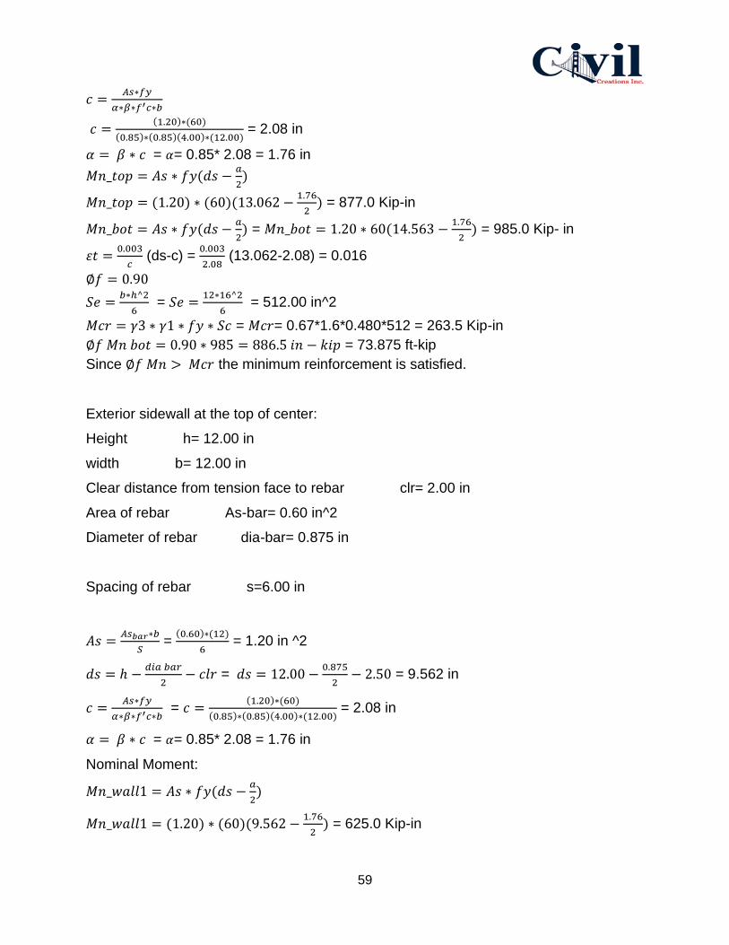
59
𝑐 =𝐴𝑠∗𝑓𝑦
𝛼∗𝛽∗𝑓′𝑐∗𝑏
𝑐 =(1.20)∗(60)
(0.85)∗(0.85)(4.00)∗(12.00) = 2.08 in
𝛼 = 𝛽 ∗ 𝑐 = 𝛼= 0.85* 2.08 = 1.76 in
𝑀𝑛_𝑡𝑜𝑝 = 𝐴𝑠 ∗ 𝑓𝑦(𝑑𝑠 −𝑎
2)
𝑀𝑛_𝑡𝑜𝑝 = (1.20) ∗ (60)(13.062 −1.76
2) = 877.0 Kip-in
𝑀𝑛_𝑏𝑜𝑡 = 𝐴𝑠 ∗ 𝑓𝑦(𝑑𝑠 −𝑎
2) = 𝑀𝑛_𝑏𝑜𝑡 = 1.20 ∗ 60(14.563 −
1.76
2) = 985.0 Kip- in
𝜀𝑡 =0.003
𝑐 (ds-c) =
0.003
2.08 (13.062-2.08) = 0.016
∅𝑓 = 0.90
𝑆𝑒 =𝑏∗ℎ^2
6 = 𝑆𝑒 =
12∗16^2
6 = 512.00 in^2
𝑀𝑐𝑟 = 𝛾3 ∗ 𝛾1 ∗ 𝑓𝑦 ∗ 𝑆𝑐 = 𝑀𝑐𝑟= 0.67*1.6*0.480*512 = 263.5 Kip-in
∅𝑓 𝑀𝑛 𝑏𝑜𝑡 = 0.90 ∗ 985 = 886.5 𝑖𝑛 − 𝑘𝑖𝑝 = 73.875 ft-kip
Since ∅𝑓 𝑀𝑛 > 𝑀𝑐𝑟 the minimum reinforcement is satisfied.
Exterior sidewall at the top of center:
Height h= 12.00 in
width b= 12.00 in
Clear distance from tension face to rebar clr= 2.00 in
Area of rebar As-bar= 0.60 in^2
Diameter of rebar dia-bar= 0.875 in
Spacing of rebar s=6.00 in
𝐴𝑠 =𝐴𝑠𝑏𝑎𝑟∗𝑏
𝑆 =
(0.60)∗(12)
6 = 1.20 in ^2
𝑑𝑠 = ℎ −𝑑𝑖𝑎 𝑏𝑎𝑟
2− 𝑐𝑙𝑟 = 𝑑𝑠 = 12.00 −
0.875
2− 2.50 = 9.562 in
𝑐 =𝐴𝑠∗𝑓𝑦
𝛼∗𝛽∗𝑓′𝑐∗𝑏 = 𝑐 =
(1.20)∗(60)
(0.85)∗(0.85)(4.00)∗(12.00) = 2.08 in
𝛼 = 𝛽 ∗ 𝑐 = 𝛼= 0.85* 2.08 = 1.76 in
Nominal Moment:
𝑀𝑛_𝑤𝑎𝑙𝑙1 = 𝐴𝑠 ∗ 𝑓𝑦(𝑑𝑠 −𝑎
2)
𝑀𝑛_𝑤𝑎𝑙𝑙1 = (1.20) ∗ (60)(9.562 −1.76
2) = 625.0 Kip-in
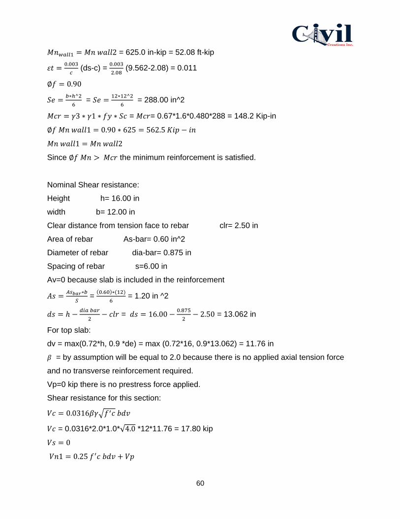
60
𝑀𝑛𝑤𝑎𝑙𝑙1 = 𝑀𝑛 𝑤𝑎𝑙𝑙2 = 625.0 in-kip = 52.08 ft-kip
𝜀𝑡 =0.003
𝑐 (ds-c) =
0.003
2.08 (9.562-2.08) = 0.011
∅𝑓 = 0.90
𝑆𝑒 =𝑏∗ℎ^2
6 = 𝑆𝑒 =
12∗12^2
6 = 288.00 in^2
𝑀𝑐𝑟 = 𝛾3 ∗ 𝛾1 ∗ 𝑓𝑦 ∗ 𝑆𝑐 = 𝑀𝑐𝑟= 0.67*1.6*0.480*288 = 148.2 Kip-in
∅𝑓 𝑀𝑛 𝑤𝑎𝑙𝑙1 = 0.90 ∗ 625 = 562.5 𝐾𝑖𝑝 − 𝑖𝑛
𝑀𝑛 𝑤𝑎𝑙𝑙1 = 𝑀𝑛 𝑤𝑎𝑙𝑙2
Since ∅𝑓 𝑀𝑛 > 𝑀𝑐𝑟 the minimum reinforcement is satisfied.
Nominal Shear resistance:
Height h= 16.00 in
width b= 12.00 in
Clear distance from tension face to rebar clr= 2.50 in
Area of rebar As-bar= 0.60 in^2
Diameter of rebar dia-bar= 0.875 in
Spacing of rebar s=6.00 in
Av=0 because slab is included in the reinforcement
𝐴𝑠 =𝐴𝑠𝑏𝑎𝑟∗𝑏
𝑆 =
(0.60)∗(12)
6 = 1.20 in ^2
𝑑𝑠 = ℎ −𝑑𝑖𝑎 𝑏𝑎𝑟
2− 𝑐𝑙𝑟 = 𝑑𝑠 = 16.00 −
0.875
2− 2.50 = 13.062 in
For top slab:
dv = max(0.72*h, 0.9 *de) = max (0.72*16, 0.9*13.062) = 11.76 in
𝛽 = by assumption will be equal to 2.0 because there is no applied axial tension force
and no transverse reinforcement required.
Vp=0 kip there is no prestress force applied.
Shear resistance for this section:
𝑉𝑐 = 0.0316𝛽𝛾√𝑓′𝑐 𝑏𝑑𝑣
𝑉𝑐 = 0.0316*2.0*1.0*√4.0 *12*11.76 = 17.80 kip
𝑉𝑠 = 0
𝑉𝑛1 = 0.25 𝑓′𝑐 𝑏𝑑𝑣 + 𝑉𝑝

61
𝑉𝑛1 = 0.25 ∗ 4 ∗ 12 ∗ 11.76 + 0 = 141.1 𝑘𝑖𝑝
𝑉𝑛2 = 𝑉𝑐 + 𝑉𝑠 + 𝑉𝑝
𝑉𝑛2 = 17.80 + 0 + 0 = 17.80 𝑘𝑖𝑝
𝑉𝑛 − 𝑠𝑒𝑐2 = (𝑉𝑛1, 𝑉𝑛2) = (141.1,17.8) = 17.8 𝑘𝑖𝑝
4.6.3 Rebar Determination
Since the tunnel will be installed underground with less tension and is expected less flexure.
Along with rebar size and spacing requirements along with minimum area. Based on reinforced
concrete beam design, rebar size design for tunnel was considered, which they are fy= 60 ksi and
f’c= 40ksi. The most suitable rebar size is rebar #12, with bar diameter 1.5 in, and minimum
spacing 1 in.
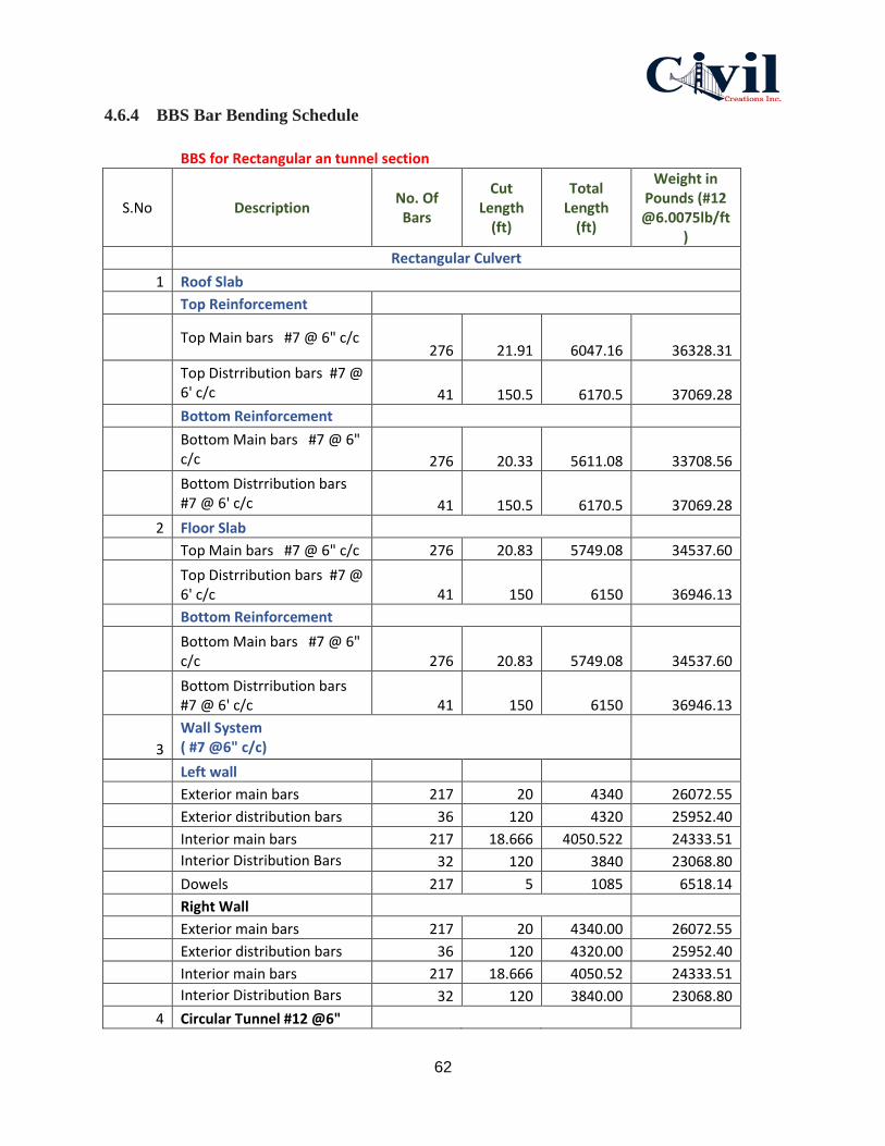
62
4.6.4 BBS Bar Bending Schedule
BBS for Rectangular an tunnel section
S.No Description No. Of Bars
Cut Length
(ft)
Total Length
(ft)
Weight in Pounds (#12 @6.0075lb/ft
)
Rectangular Culvert
1 Roof Slab
Top Reinforcement
Top Main bars #7 @ 6" c/c
276 21.91 6047.16 36328.31
Top Distrribution bars #7 @ 6' c/c 41 150.5 6170.5 37069.28
Bottom Reinforcement
Bottom Main bars #7 @ 6" c/c 276 20.33 5611.08 33708.56
Bottom Distrribution bars #7 @ 6' c/c 41 150.5 6170.5 37069.28
2 Floor Slab
Top Main bars #7 @ 6" c/c 276 20.83 5749.08 34537.60
Top Distrribution bars #7 @ 6' c/c 41 150 6150 36946.13
Bottom Reinforcement
Bottom Main bars #7 @ 6" c/c 276 20.83 5749.08 34537.60
Bottom Distrribution bars #7 @ 6' c/c 41 150 6150 36946.13
3
Wall System ( #7 @6" c/c)
Left wall
Exterior main bars 217 20 4340 26072.55
Exterior distribution bars 36 120 4320 25952.40
Interior main bars 217 18.666 4050.522 24333.51
Interior Distribution Bars 32 120 3840 23068.80
Dowels 217 5 1085 6518.14
Right Wall
Exterior main bars 217 20 4340.00 26072.55
Exterior distribution bars 36 120 4320.00 25952.40
Interior main bars 217 18.666 4050.52 24333.51
Interior Distribution Bars 32 120 3840.00 23068.80
4 Circular Tunnel #12 @6"

63
c/c)
Outer side reinforcement 126 150.5 18963.00 113920.22
Inner Side reinforcement 107 150.5 16103.50 96741.78
Table 4: Bar Bending Schedule.
4.7 Temporary Structure
4.7.1 Shoring
Excavation depth is 22 feet which allows us to use soldier beams with tiebacks to make direct
contact to the soil which will result in bearing and side pressure. In Figure 14 provides a shoring
system component with two- pair strand tieback system that will be used for the project. The
materials that make up these systems are usually high strength steel ranging in allowable stresses
between 60 and 120 ksi.
Figure 14: Shoring System Component
The system will be supported by sheet piles to avoid considerable settlement or bearing capacity
failure of the soil. Struts and walers are used to support the sheet piles as shown in Figure 15.

64
Figure 15: Sheet pile with strut and waler system
Using Z- shaped hot rolled sheet piles where the interlocks are shaped while the steel is formable
as shown in Figure16. This makes the interlock tight, which means less water or soil can
penetrate the interlock joint.
Figure 16: Z- shape hot rolled sheet pile

65
The lower hinge point is located at 3 feet below the bottom of excavation as shown in Figure 17
along with horizontal strut spacing. Strut and waler are spaced at 17.5 feet on center with taking
in consideration the size of the boring machine.
Figure17 : Strut spacing
4.7.2 Sheet Piles
Based on the Geotechnical report the maximum soil pressure is 1900 psf and the
pressure is uniform across the height of the sheet pile wall.
L= 8’+ 3’ = 11ft
𝑉𝑚𝑎𝑥 = 0.6 𝑤𝑙
Vmax=0.6 x 1.9 kips x 11 ft =12.54 Kips
Maximum moment =𝑤𝑙^2
10
Maximum moment = 1.9 𝑥 (11)^2
10 = 22.99 Kips. ft
Section modulus = (22.99 kip.ft x 12 in/ft) / 21.6 ksi= 12.78 in3
From sheet pile (Skyline), we pick AZ 12-700 S= 22.3 in3 most economical hot
rolled sheet pile.
4.7.3 Waler

66
As we are using A36 steel with an allowable bending stress of Fb= 21.6 Ksi. selecting
the most economical W shape beam steps for the lower waler as follow
W = Maximum pressure x Tributary height=1.9 Kips x 7 + 112= 17.1 Kips
Maximum moment = wl2 /8= 17.1 𝑥 (17.5)^2
8 = 654.61 Kips. ft
Section modulus = Mmax / Fb= 654.61 𝑘𝑖𝑝.𝑓𝑡 𝑥 12 𝑖𝑛/𝑓𝑡
21.6 𝑘𝑠𝑖 = 363.67 in3
From AISC steel beams manual
The W24 x 146 with Section modulus of 371, it is the most safe and economical w
shape to use for waler.
4.7.4 Strut
The strut can be designed for any system. The design of the strut is determined by axial
load, unsupported length of the strut and the end connection.
For Coronado pedestrian tunnel project, the Strut length is 10 ft and it has 260-kip
capacity, assume k= 1.0 and r = 3 inches which is the weak direction of gyration.
Assuming 3 inches because this is an average of range of beams that are commonly
used as struts.
SR = 𝑘𝑙
𝑟 =
1.0 𝑥 10 𝑥 12"
3" = 40
From AISC allowable buckling stresses for A36 ( Fb= 19.19 ksi)
A (Area) = P capacity x Fb=260 ksi x 19.19 ksi= 13.55 in2
From AISC H pile (AISC) HP shape is HP12 x 87 (r = 2.86, A= 15.5)
SR = 𝑘𝑙
𝑟 =
1.0 𝑥 10 𝑥 12"
2.86" = 42
From AISC allowable buckling stresses for A36 ( Fb= 19.02 ksi)
Pallowable= Fbs x A= 19.02 x 15.5= 294.81 kips
294.81(Pall) > 260 (Pact) the strut works, since our Pallowable greater than Pact.
4.7.5 Formwork
Formwork is a temporary mold that is used to support the concrete poured into the
molds. The best formwork for this project is Plywood for concrete. It is the most strong,
efficient, and economic because it is the most repeated use once. One of the best
advantages is providing a smooth finishing of concrete and it can be easily forming the

67
required size. The best size of plywood is 8’X 4’’ (2440 X 1220 MM), and the plywood
grade is MR grade plywood that it is moisture resisting as shown in Figure 18.
Figure18: Formwork
4.8 Conclusion and Recommendation
Based on the analysis and structural calculation for the designed tunnel in this report. A
circular tunnel with outer radius 10 feet and inner radius 8.5 feet, a length of 140 feet.
Type of concrete is Alkali concrete; it will be reinforced with #12 rebar (bar diameter =
1.5 inch) with spacing of 1 inch. The concrete of the underground tunnel can take a total
load of 15,431.25 𝑖𝑏 − 𝑓𝑡. The wall system is 144 cubic yards for both sides, the roof
and floor slab are 102 cubic yards respectively as shown in Figure 19.
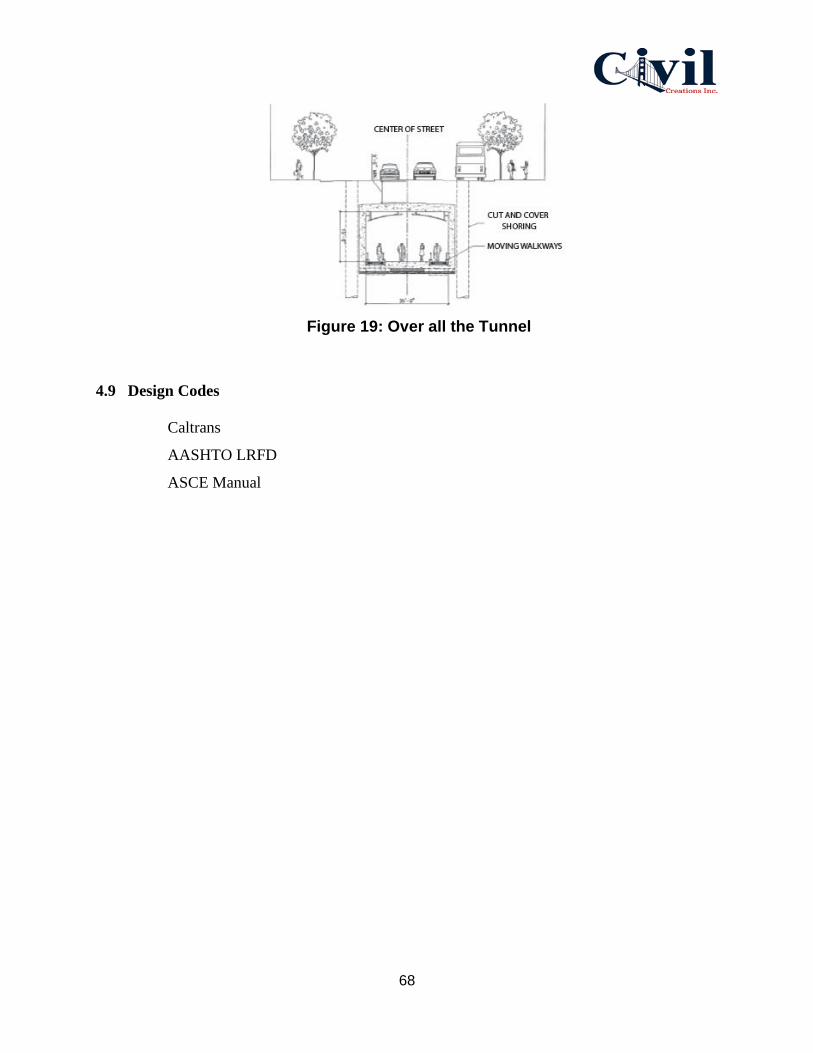
68
Figure 19: Over all the Tunnel
4.9 Design Codes
Caltrans
AASHTO LRFD
ASCE Manual
69
Appendix 5: Construction Management Report
Coronado NAB Pedestrian Tunnel
Final Design Submittal by Civil Creations Inc.
Team 22
May 6th, 2020

70
Table of Contents
Appendix 5: Construction Management
5.1ProjectDescription……………………………………………….…73
5.2 Summary of Site Attributes…………………………….…...…....73
5.2.1 Site Details.…………………………………..……………....…...73
5.2.2 Hours of Work ..…………………………………………....…....74
5.2.3 Pre-start checks.…………………………………………………74
5.3 Equipment Selection ………………………………………..…....74
5.3.1 EC350E Volvo excavator………………….………..…….….…75
5.3.2 Street Sweeper …….……………………………...……….…....75
5.3.3 Crane ………………...………………………………….………...76
5.3.4 Dump Trucks …………………………………………………….76
5.3.5 Grader ………………………………………………….………….77
5.3.6 Compactor …………...………………………………….………..77
5.3.7 Tunnel Boring Machine …………..…………………….………77
5.4 Site Logistic Plan …….………………….………………………..78
5.4.1 Security / Safety ..………………………………………….…....78
5.4.2 Trucks Haul Routes.……………. ……………………….……..78
5.4.3 Office and Equipment Trailer.………. ………………..……....88
5.4.4 Parking……..…………………………………………….…….….88
5.4.5 Laydown and Deliveries Area……..………………..………….88
5.4.6 Crane and Equipment Ways……..……….………….……...…89
5.4.7 Waste Management………………………………………..…….89
5.4.8 Environmental Impact Protection…….……………………....89

71
5.4.9 SWPPP and BMP’s…….……………………….……………...…..89
5.5 Coordination Requirements …….…………………….…..…….....90
5.5.1 Personnel…………………….…….………………….………..…...91
5.5.2 Risk Assessments……………..…....…….………………..…......91
5.6 Construction Material……………..…….………..………………....91
5.7 Construction Phasing……………..…………..………..……..….…93
5.7.1 Establish Budget…………….…………………….…………….…94
5.7.2 Preconstruction……………..…….….…..……………....…….….94
5.7.3 Demolish…………………………………………………..…………94
5.7.4 Earthwork…………………………………………………..…..……94
5.7.5 Structure…………………………………………..….………...……97
5.7.6 Interiors / Finishes……………………………..……….…….……98
5.7.7 Electrical Works………………………………………….…...……98 List of Figures:
Figure 5.20 Site Layout ………….………………………….……..……73
Figure 5.21 Excavator and Truck Loading Area… ………..….…….75
Figure 5.22 Truck Production Cycle …………...…………….……….76
Figure 5.23 Site Logistic Plan, West Side Truck Haul ……..………79
Figure 5.24 Site Logistic Plan, East Side Truck Haul ………..…….85
Figure 5.25 SWPPP & BMPs …………..…………….……….…………90
Figure 5.26 Components of Shield Machine …………………………92
Figure 5.27 Tunnel Boring Machine ……...……………………………93
Figure 5.28 Demolish …………………………………………………….95
Figure 5.29 Boring Machine Location ………..……………………….96
Figure 30: North Side Excavation ……………………………………..97
72
List of Tables
Table 5.5 Fill Factor ………………………………………………………..80
Table 5.6 Representative of Earth and Rock………..…….…….……..81
Table 5.7 Fixed Cycle time for Loaders…………………….…..……….82
Table 5.8 Rolling Resistance ………………………………………...…..83

73
Appendix 5: Construction Management.
5.1 Project Description
The site is located at Coronado Island in California. The construction site in question lies within
a reasonable level terrain and on a stable ground.
The proposed site plan shown in Figure 20 includes the proposed location of the pedestrian
tunnel with access ramps and stairways. Boring machine location, work area, employees parking,
laydown and deliveries area, office and equipment trailers. During construction and heavy
machine operations, there will be one line blocked on the West side of the tunnel between
Tarawa Road and Rendova Road.
Figure 20: Site Layout
5.2 Summary of Site Attributes
5.2.1 Site Details
1. Location: Coronado Island, Intersection Tarawa Rd and SR-75
2. Contract Type: Design Bid- Build

74
3. Final Project Cost: $3,138,390.00
4. Architect: The Boring Company
5. Excavation Contractor: Precision Excavation and Demolition
6. Concrete Contractor: K&L Contracting, Inc.
7. Steel: Rossin Steel
8. Frames: Nevel
9. MEP: Baker electric
10. Demolition Contractor: Precision Excavation and Demolition
11. Project Managers (PM): Mina Ghareeb
12. Commencement Date: 06 July 2020
13. Completion Date: 16 January 2023
5.2.2 Hours of Work
The official work hours are as stipulated below but subject to pay overtime hours when the need
arises:
Monday - Friday / 6:00 am - 2:30 pm
5.2.3 Pre-start checks
The construction works pre-start checks must cover the following key areas:
1. Availability of suitable plants and equipment to be used on site for specified works, based
on the work schedule, ground stability and interruption of activities in case of adverse
weather conditions.
2. Proximity hazards and safety risks in all relevant and designated areas.
5.3 Equipment Selection
The initial equipment selection is normally based on the size of the construction project and the
overall development process. The key considerations during equipment selection are depth of
excavations, production targets and the methods of construction. Noted is that the number and
size of equipment were majorly calculated based on production rate and the project schedule.

75
5.3.1 EC350E Volvo excavator
The EC350E Excavator is a powerful production machine that is designed to increase
productivity. It has a 3.5 bucket size and swing angle of 40°- 60°. Featuring a robust D13 Tier 4
Final engine, a new electro-hydraulic control system and Volvo's unique ECO mode, these
heavy-duty excavators deliver up to 9% greater fuel efficiency. It’s located on site layout as
shown in Figure 21 along with trucks loading area which that will give a better production and
faster time to load.
Figure 21: Excavator and Trucks Loading Area
5.3.2 Street sweeper
Tennant Sentinel Street Sweeper needed for construction projects because projects commonly
produce huge amounts of dust and debris, which can be blown away or spilled over by trucks on
the road around the site. Without regular cleanup, adjacent roads can be covered with dust and
debris on a regular basis throughout the duration of the project.

76
5.3.3 Crane
The gantry crane is going to be used for this project which is specified for underground
construction such as tunnels so that it can fit small areas. The crane capacity is 20-50 tons for
material handling of tunnels. It is mainly employed to lift the cutter and shield plate of tunnel
boring machines. The lifting mechanism of this gantry crane is rotatable for different digging
directions. It is designed with safety instructions and an overload protection device system.
5.3.4 Dump Trucks
Dump trucks will have a 18 bucket size and will be required to complete one cycle of an activity
in a production process as shown in Figure 22. Contractor goal is to move and haul as much
material and in the shortest time possible. The cycle time for the amount of trucks a day will be
an estimated certain number of trips as it will be calculated later in the report.
Figure 22: Truck Production Cycle

77
5.3.5 Grader
Grader used to create a flat surface during the grading process. The grader type that is going to
be used on this project is articulated frame motor graders: These usually have both a front and
rear axle. The blade is usually located somewhere between the two axles. The articulated frame
graders are usually in small places where there is very less space to move and turnabout in.
5.3.6 Compactor
A normal plate compactor (slope compactor) is going to be used for the main volume of the
backfill and a smaller compactor for the roof section, 15 t Volvo Backhoe loader. The same
Volvo Backhoe loader is going to be used for placing the material on the layer with the help of a
bucket loader and a leveler attached to the boom of the backhoe. The plate compactor is going to
be attached to the same boom, requiring change of instruments between the different work
stages. Whenever more space is needed, the loader is going to be driven away from the tunnel.
5.3.7 Tunnel Boring Machine
Bored tunnels are constructed with TBMs, which are shield systems led by drill bits mounted on
a rotating cutter head that excavates a circular opening. These machines can be modified for use
with varying ground types. The shape of nearly all TBM tunnels is circular. Earth
Pressure Balance Machines (EPB) is going to be used for this project. It is used in soft
ground with less than 7 bars of pressure. The cutter head does not use disc cutters
only, but instead a combination of tungsten carbide cutting bits, carbide disc cutters,
drag picks and/or hard rock disc cutters. Pressure is maintained in the cutter head by
controlling the rate of extraction of spoil through the Archimedes screw and the advance
rate. Additives such as bentonite, polymers and foam can be injected ahead of the face
to increase the stability of the ground. We will be using this machine in order to build the
tunnel without excavating the ground surface. The weight of EPB is going to be 30 tons.
78
5.4 Site Logistics Plan
5.4.1 Security / Safety
The perimeter fence is erected around the site to block passage and to prevent the view from
buildings adjacent to the construction site.
Proper safety and warning signs are appropriately placed to serve as safety precautions. The
signages are elected on designated points, along with the perimeter fence, and at the entry points.
5.4.2 Trucks Haul Routes
On the west side of the tunnel and during work hours of excavation, excavator and boring
machine will take place, trucks will be going in cycles to load from the loading area and dump at
the dump site. Dump site is located on the southwest side of the proposed tunnel location As
shown in Figure 23. As calculated, approximately 2916 cy of soil taking out from the proposed
tunnel location. The cycle time for each truck would be 8.61 minutes. Also, the truck cycle will
include 4 buckets and 4 trucks for 418.12 Lcy as shown in calculations below.

79
Figure 23: Site Logistic Plan; West side Truck Haul
Excavator bucket size: 3.5 cy
Excavator Swing Angle= 40°- 60°
Truck Bucket Load Capacity = 18 cy
Material type is Sandy Clay
Step 1: Bucket Load Weight

80
From Table 5, the fill factor for Sandy Clay material is 105%
Table 5: Fill Factor
Bucket Capacity= 3.5x 10⁵%= 3.675 cy
𝐵𝑢𝑐𝑘𝑒𝑡 𝐿𝑜𝑎𝑑 =𝑇𝑟𝑢𝑐𝑘 𝐶𝑎𝑝𝑎𝑐𝑖𝑡𝑦
𝐵𝑢𝑐𝑘𝑒𝑡 𝐶𝑎𝑝𝑎𝑐𝑖𝑡𝑦=
18 𝑐𝑦
3.675= 4.898
Due to some of the materials that could spill off during the load,
4 x Bucket Capacity
4 x 3.675 = 15 Lcy
From Table 6, find the unit weight of Sandy Clay material

81
Table 6: Representative of Earth and Rock
𝐿𝑜𝑎𝑑 𝑊𝑒𝑖𝑔ℎ𝑡 = 2200 𝑙𝑏/𝑐𝑦 𝑥 15 𝑙𝑐𝑦=3300 lb
Load Weight = 33000 𝑙𝑏
2000 𝑙𝑏𝑠/ 𝑡𝑜𝑛𝑠= 16.5 𝐿𝑜𝑎𝑑 𝑤𝑒𝑖𝑔ℎ𝑡 𝑤ℎ𝑖𝑐ℎ 𝑖𝑡 𝑤𝑖𝑙𝑙 𝑏𝑒 𝑂𝑘
Step 2: Load Bucket Time
Table 7, to find the Wheel Loader cycle time

82
Table 7: Fixed Cycle time for Loader
For Coronado pedestrian tunnel project, using Loader with heaped capacity varies between 4.00-
5.00 cy
Based to Table 7, Wheel loader cycle time (sec) = 30-33 sec
Avg. wheel loader cycle time = 31.5
60 𝑚𝑖𝑛= 0.525 𝑚𝑖𝑛
Contractor decided to use 4 buckets x 0.525 min = 2.10 minutes for Loading time
Step 3: Haul time
Total Resistance (TR) = Rolling Resistance (RR) + Grade Resistance (GR)
Table 8, to find the rolling resistance as it appears to be asphalt (50 - 60 lb./ton)

83
Table 8: Rolling Resistance
𝑇𝑜𝑡𝑎𝑙 𝑅𝑒𝑠𝑖𝑠𝑡𝑎𝑛𝑐𝑒 = ((50 + 60)/2
20 𝑙𝑏/ 𝑡𝑜𝑛𝑒) − 0 = 2.75%
𝑇𝑟𝑢𝑐𝑘 𝑊𝑒𝑖𝑔ℎ𝑡 =36860 𝑙𝑏𝑠
2000 𝑙𝑏/ 𝑡𝑜𝑛𝑠= 18.43 𝑡𝑜𝑛𝑠
Total weight = Load weight + Truck Weight
Total weight = 16.5 + 18.43= 34.93 tons
2.75% x 20 lb/ tone x 34.93 tone = 20 lbs
𝑇𝑟𝑢𝑐𝑘 𝐻𝑎𝑢𝑙 =0.096 𝑚𝑖𝑙𝑒𝑠
5 𝑚𝑝ℎ𝑥 60 𝑚𝑖𝑛𝑡𝑠 = 1.152 minutes
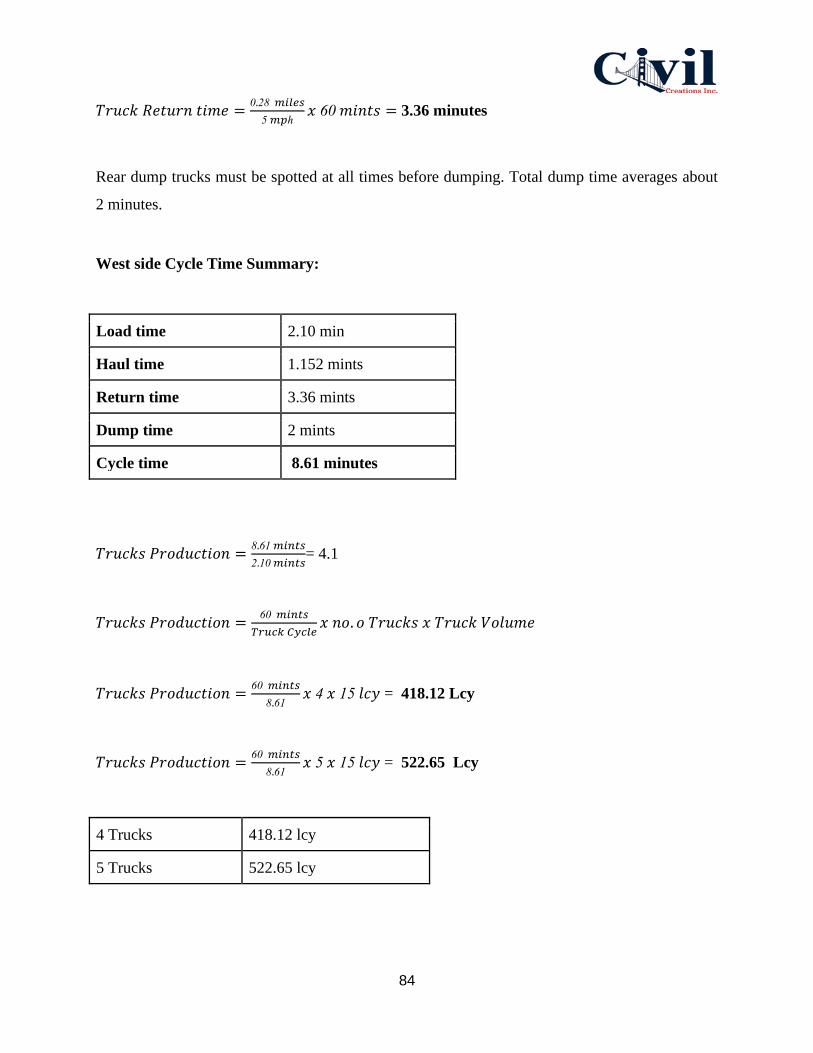
84
𝑇𝑟𝑢𝑐𝑘 𝑅𝑒𝑡𝑢𝑟𝑛 𝑡𝑖𝑚𝑒 =0.28 𝑚𝑖𝑙𝑒𝑠
5 𝑚𝑝ℎ𝑥 60 𝑚𝑖𝑛𝑡𝑠 = 3.36 minutes
Rear dump trucks must be spotted at all times before dumping. Total dump time averages about
2 minutes.
West side Cycle Time Summary:
Load time 2.10 min
Haul time 1.152 mints
Return time 3.36 mints
Dump time 2 mints
Cycle time 8.61 minutes
𝑇𝑟𝑢𝑐𝑘𝑠 𝑃𝑟𝑜𝑑𝑢𝑐𝑡𝑖𝑜𝑛 =8.61 𝑚𝑖𝑛𝑡𝑠
2.10 𝑚𝑖𝑛𝑡𝑠= 4.1
𝑇𝑟𝑢𝑐𝑘𝑠 𝑃𝑟𝑜𝑑𝑢𝑐𝑡𝑖𝑜𝑛 =60 𝑚𝑖𝑛𝑡𝑠
𝑇𝑟𝑢𝑐𝑘 𝐶𝑦𝑐𝑙𝑒𝑥 𝑛𝑜. 𝑜 𝑇𝑟𝑢𝑐𝑘𝑠 𝑥 𝑇𝑟𝑢𝑐𝑘 𝑉𝑜𝑙𝑢𝑚𝑒
𝑇𝑟𝑢𝑐𝑘𝑠 𝑃𝑟𝑜𝑑𝑢𝑐𝑡𝑖𝑜𝑛 =60 𝑚𝑖𝑛𝑡𝑠
8.61𝑥 4 𝑥 15 𝑙𝑐𝑦 = 418.12 Lcy
𝑇𝑟𝑢𝑐𝑘𝑠 𝑃𝑟𝑜𝑑𝑢𝑐𝑡𝑖𝑜𝑛 =60 𝑚𝑖𝑛𝑡𝑠
8.61𝑥 5 𝑥 15 𝑙𝑐𝑦 = 522.65 Lcy
4 Trucks 418.12 lcy
5 Trucks 522.65 lcy

85
As a result, the combination of bucket loads and trucks to provide the most economic operation
would be 4 buckets and 4 trucks for 418.12 Lcy.
When work begins on the other side of the Tunnel (East side), there will be another truck haul
cycle going in rotation. Existing dump site is to Tarawa Road to stop at the loading area of the
Tunnel. After loading, trucks will be making a left at Rendova Road to go back to dump at the
dump site as shown in Figure 24. The cycle time for each truck would be 9.11 minutes. Also, the
truck cycle will include 4 buckets and 4 trucks for 395.17 Lcy as shown in calculations below.
Figure 24: Site Logistic Plan; East side Truck Haul
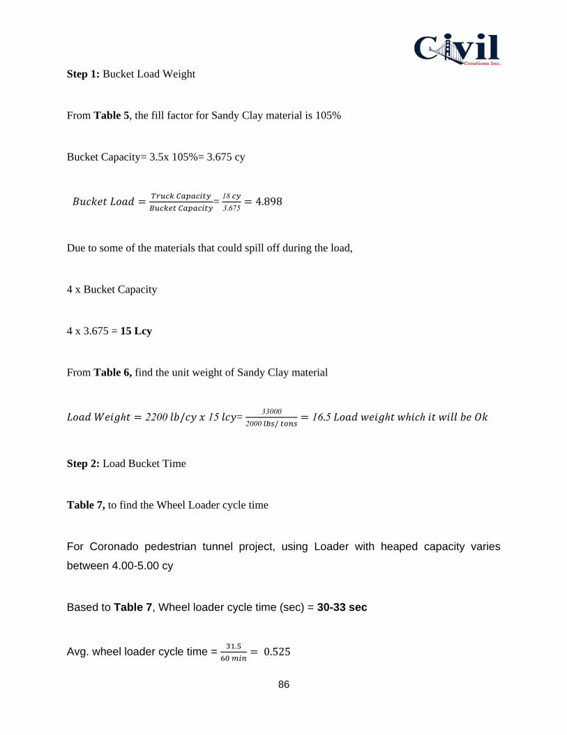
86
Step 1: Bucket Load Weight
From Table 5, the fill factor for Sandy Clay material is 105%
Bucket Capacity= 3.5x 10⁵%= 3.675 cy
𝐵𝑢𝑐𝑘𝑒𝑡 𝐿𝑜𝑎𝑑 =𝑇𝑟𝑢𝑐𝑘 𝐶𝑎𝑝𝑎𝑐𝑖𝑡𝑦
𝐵𝑢𝑐𝑘𝑒𝑡 𝐶𝑎𝑝𝑎𝑐𝑖𝑡𝑦=
18 𝑐𝑦
3.675= 4.898
Due to some of the materials that could spill off during the load,
4 x Bucket Capacity
4 x 3.675 = 15 Lcy
From Table 6, find the unit weight of Sandy Clay material
𝐿𝑜𝑎𝑑 𝑊𝑒𝑖𝑔ℎ𝑡 = 2200 𝑙𝑏/𝑐𝑦 𝑥 15 𝑙𝑐𝑦= 33000
2000 𝑙𝑏𝑠/ 𝑡𝑜𝑛𝑠= 16.5 𝐿𝑜𝑎𝑑 𝑤𝑒𝑖𝑔ℎ𝑡 𝑤ℎ𝑖𝑐ℎ 𝑖𝑡 𝑤𝑖𝑙𝑙 𝑏𝑒 𝑂𝑘
Step 2: Load Bucket Time
Table 7, to find the Wheel Loader cycle time
For Coronado pedestrian tunnel project, using Loader with heaped capacity varies
between 4.00-5.00 cy
Based to Table 7, Wheel loader cycle time (sec) = 30-33 sec
Avg. wheel loader cycle time = 31.5
60 𝑚𝑖𝑛= 0.525

87
Contractor decided to use 4 Buckets x 0.525= 2.10 minutes for Loading time
Step 3: Haul time
Total Resistance (TR) = Rolling Resistance (RR) + Grade Resistance (GR)
Table 8 to find the rolling resistance as it appears to be asphalt (50 - 60 lb./ton)
𝑇𝑜𝑡𝑎𝑙 𝑅𝑒𝑠𝑖𝑠𝑡𝑎𝑛𝑐𝑒 = ((50 + 60)/2
20 𝑙𝑏/ 𝑡𝑜𝑛𝑒) − 0 = 2.75%
𝑇𝑟𝑢𝑐𝑘 𝑊𝑒𝑖𝑔ℎ𝑡 =36860 𝑙𝑏𝑠
2000 𝑙𝑏/ 𝑡𝑜𝑛𝑠= 18.43 𝑡𝑜𝑛𝑠
Total weight = Load weight + Truck Weight
Total weight = 16.5 + 18.43= 34.93 tons
2.75% x 20 lb./ tone x 34.93 = 20 lbs.
𝑇𝑟𝑢𝑐𝑘 𝐻𝑎𝑢𝑙 =0.303 𝑚𝑖𝑙𝑒𝑠
5 𝑚𝑝ℎ𝑥 60 𝑚𝑖𝑛𝑡𝑠 = 3.64 minutes
𝑇𝑟𝑢𝑐𝑘 𝑅𝑒𝑡𝑢𝑟𝑛 𝑡𝑖𝑚𝑒 =0.114 𝑚𝑖𝑙𝑒𝑠
5 𝑚𝑝ℎ𝑥 60 𝑚𝑖𝑛𝑡𝑠 = 1.37 minutes
Rear dump trucks must be spotted at all times before dumping. Total dump time
averages about 2 minutes.
East side Cycle Time Summary:
Load time 2.10 min
Haul time 3.64 mints

88
Return time 1.37 mints
Dump time 2 mints
Cycle time 9.11 minutes
𝑇𝑟𝑢𝑐𝑘𝑠 𝑃𝑟𝑜𝑑𝑢𝑐𝑡𝑖𝑜𝑛 =9.11 𝑚𝑖𝑛𝑡𝑠
2.10 𝑚𝑖𝑛𝑡𝑠= 4.3
𝑇𝑟𝑢𝑐𝑘𝑠 𝑃𝑟𝑜𝑑𝑢𝑐𝑡𝑖𝑜𝑛 =60 𝑚𝑖𝑛𝑡𝑠
𝑇𝑟𝑢𝑐𝑘 𝐶𝑦𝑐𝑙𝑒𝑥 𝑛𝑜. 𝑜 𝑇𝑟𝑢𝑐𝑘𝑠 𝑥 𝑇𝑟𝑢𝑐𝑘 𝑉𝑜𝑙𝑢𝑚𝑒
𝑇𝑟𝑢𝑐𝑘𝑠 𝑃𝑟𝑜𝑑𝑢𝑐𝑡𝑖𝑜𝑛 =60 𝑚𝑖𝑛𝑡𝑠
9.11𝑥 4 𝑡𝑟𝑢𝑐𝑘𝑠 𝑥 15 𝑙𝑐𝑦 = 395.17 Lcy
𝑇𝑟𝑢𝑐𝑘𝑠 𝑃𝑟𝑜𝑑𝑢𝑐𝑡𝑖𝑜𝑛 =60 𝑚𝑖𝑛𝑡𝑠
9.11𝑥 5 𝑡𝑟𝑢𝑐𝑘𝑠 𝑥 15 𝑙𝑐𝑦 = 493.96 Lcy
4 Trucks 395.17 Lcy
5 Trucks 493.96 Lcy
As a result, the combination of bucket loads and trucks to provide the most economic
operation would be 4 buckets and 4 trucks for 395.17 Lcy.
5.4.3 Office and Equipment Trailers
The office and equipment trailer are temporary structures that serve as documentation and
equipment storage rooms in addition to being avenues for site meetings.
5.4.4 Parking
Parking is located on the south west of the tunnel. It’s near to the construction site which would
give all workers the comfort and time to walk to the site.
5.4.5 Laydown and Deliveries Area

89
Required construction units and utility installation are delivered to site on approved articulated
trucks and must be directed to designate loading areas by qualified assistants.
A grounds supervisor records every detail of deliveries on site including the type, number, and
size of trunks together with the access requirements.
5.4.6 Crane & Equipment Ways
All crane and equipment movements must be authorized and are under the full control of the
grounds site supervisor. They are all located within the job site area.
5.4.7 Waste Management
The site has a goal principle of general cleanliness for health and safety of employees, visitors
and the community at large. Proper waste disposal practices are among the project’s main
objectives.
5.4.8 Environmental Impact protection
All activities associated with this site are typical to those of any construction site. Noise and dust
pollution are minimized through blanket covering along the perimeter fence and street sweeper
machine that goes around the site. The site is occasionally sprayed with water as required to
minimize dust pollution.
5.4.9 Storm Water Pollution Protection (SWPPP) / Best Management Practices (BMPs)

90
Figure 25: SWPPP & BMP’s
● Silt Fence
The Silt Fence as shown in Figure 25 is a temporary sediment control device that will go around
the dump site to protect water quality in nearby the site from sediment in stormwater runoff.
● Biofilter Bags
The biofilter as shown in Figure 25 will be placed around the drain run off, laydown area fence
and around the construction site to reduce the transport of sediment from a construction site by
providing a temporary physical barrier to sediment and reducing runoff velocities.
● Street Sweeper
Street Sweeper As shown in Figure 25 will be going around the site during construction to free
the area of dirt and debris.
5.5 Coordination requirements in order to perform work at Coronado NAB
Pedestrian Tunnel

91
5.5.1 Personnel
The construction workers employed to carry out any activity on site are experienced and
competently trained. All construction workers should have a clearance check prior to entering the
NAB area and construction site.
During project inductions, all employees are thoroughly acquainted with the schedule and the
contents of the Work Method Statement.
All vital records from site-specific orientations and training for any event are maintained by the
construction project manager within the site administration offices at all times. Any relevant
qualifications and training certificates of all employees are photocopied and kept in the project’s
personnel records file.
5.5.2 Risk Assessments
All personnel on site are made aware of the hazards and risks associated with the ongoing project
at Coronado NAB Pedestrian Tunnel project. Prior to commencement of work, every worker is
required to have sufficient knowledge of the necessary risk assessments for all materials,
equipment, and works involved.
● Hazards to Identify
● Noise
● Dust
● Knockdown Hazard
● Body injury (especially foot, hand and head injury)
● Explosion
● Manual Handling
5.6 Construction Materials
1. Materials that will be used for the Coronado Pedestrian Tunnel will depend on the
methods of geotechnical, design, and construction. In this project, there will be many
materials for the construction process.
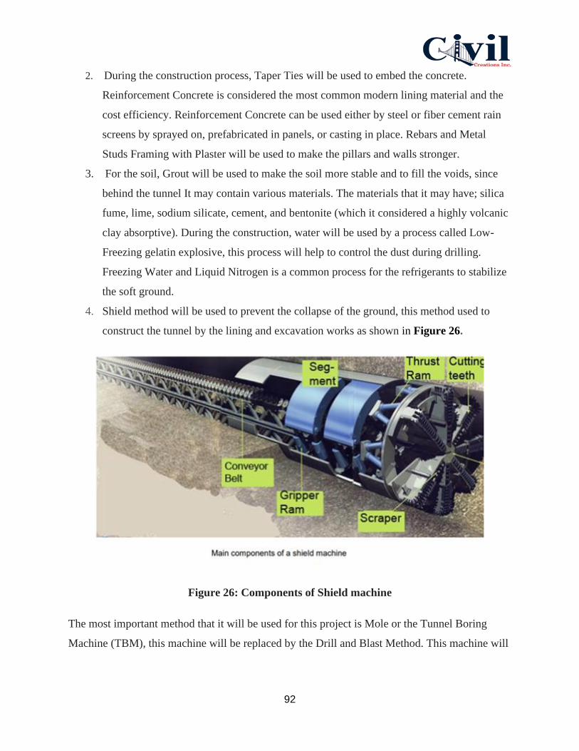
92
2. During the construction process, Taper Ties will be used to embed the concrete.
Reinforcement Concrete is considered the most common modern lining material and the
cost efficiency. Reinforcement Concrete can be used either by steel or fiber cement rain
screens by sprayed on, prefabricated in panels, or casting in place. Rebars and Metal
Studs Framing with Plaster will be used to make the pillars and walls stronger.
3. For the soil, Grout will be used to make the soil more stable and to fill the voids, since
behind the tunnel It may contain various materials. The materials that it may have; silica
fume, lime, sodium silicate, cement, and bentonite (which it considered a highly volcanic
clay absorptive). During the construction, water will be used by a process called Low-
Freezing gelatin explosive, this process will help to control the dust during drilling.
Freezing Water and Liquid Nitrogen is a common process for the refrigerants to stabilize
the soft ground.
4. Shield method will be used to prevent the collapse of the ground, this method used to
construct the tunnel by the lining and excavation works as shown in Figure 26.
Figure 26: Components of Shield machine
The most important method that it will be used for this project is Mole or the Tunnel Boring
Machine (TBM), this machine will be replaced by the Drill and Blast Method. This machine will

93
play an important role to excavate tunnels in a circular cross sectional through the soil and rock
as shown in Figure 27.
Figure 27: Tunnel Boring Machine
5.7 Construction Phasing
Scheduling → Establish Budget → Pre-Construction → Demolish → Earthwork →
Structure→ Interiors
Civil Creations Inc. will hire The Boring Company as an architect to work on schedule and
develop activities and constraints by using Primavera P6. Civil Creations Inc. requires weekly
meetings with subcontractors to increase certainty of schedule activities and schedule duration.
Monthly updates will be sent to the owner for approval and review.
Subcontractors will meet with the Superintendent and Project Manager to brainstorm on the
issues that will be very critical for the schedule.
There are several project’s risks that Civil Creations Inc will face during the construction of the
Coronado pedestrian tunnel. Potential project risks can result not only a delay of the duration of
the project schedule, but also a danger to the workers on site and nearby pedestrians in the area.

94
By addressing these problems, Civil Creations Inc. will have to take note of the safety
procedures during construction and staying on time for the completion date of the project.
5.7.1 Establish Budget
This project will eliminate an at grade crosswalk with an underground pedestrian tunnel. It’s
confirmed that many divisions will be involved such as: Preconstruction, Site Earthwork, Sub-
Structure and Site Improvement. A budget and a financial plan have been set to provide a
foundation for the delivery of services. It is estimated that the Preconstruction will shear a sum
of $342,535. Also, $1,374,965 is provided to Site Earthwork Section. Sub-Structure estimated
$1,189,640 and last Site Improvement is $231,250. Those estimations may vary depending on
site and project conditions. Finally, the total cost estimate is $3,138,390 as cost estimate details
is provided in Section 6.
5.7.2 Preconstruction
Civil Creations Inc. will have a pull planning session for certain groups of trades for each phase
of the project. All subcontractors will collaborate using backward pass to put activities into the
process. Subcontractors will meet with the Superintendent and Project Manager to brainstorm on
the issues that are very critical for the schedule and construction activities.
5.7.3 Demolish
On the east side of the tunnel, there are some bushes and trees that need to be relocated in order
to build the stairs and the ramp of the tunnel. The size of some trees are 24” in diameter and 10’
height. Bobcat e35i Mini Excavator would help in relocating and transplanting those trees in a
location that suits their habitat along the SR75. However, the remaining bushes will be recycled
instead of relocating them.
5.7.4 Earthwork
Earth work operation will include demolishing the trees and excavation. The trees are on the
north east side of the Tunnel, as shown in Figure 28.

95
Figure 28: Demolish
Excavation works will be ongoing on the other side with the EC350E VOLVO excavator
assisting in the ground digging to reach a target depth of 22 feet. There will be a truck haul cycle
on going to load and dump the soil.
Boring machine will take place after reaching the depth of 22 feet. As shown in Figure 29 the
boring machine location.

96
Figure 29: Boring Machine Location
Moving forward, there will be an excavation on the north side of the tunnel for a stairway and
access ramp as shown in Figure 30. The project will have another truck cycle to load and dump
the soil at the dump site.

97
Figure 30: North Side Excavation

98
5.7.5 Structure
Due to the weak nature of the soil, shoring and strutted hot rolled sheet piles will be required to
support the excavation. Strutted hot rolled sheet piles good for retaining soils and provides better
water resistance. The interlocked sheet piles form a wall for permanent or temporary lateral earth
support with reduced groundwater flow. First, sheet piles will be driven to the required depth (22
feet). Excavator digs a 5 feet bench around the area that it needs to be excavated. At 5 feet depth,
installation of strut with waler and shoring will be required to prevent the soil from collapse.
The process will repeat continuously until the desired depth is achieved. In addition, strut
spacing will take into consideration the size of the boring machine.
5.7.6 Interiors / Finishes
1. Flooring paving: Supply materials and execute paving tiles using cement mortar with
(1:3) mix.
2. Cement plastering: Supply and execute cement plastering with (1:3) mix, for external
concrete beams and walls.
3. Painting walls: supply materials and execute painting using oil paint for the walls.
4. False Ceiling: Supply materials & install False Ceiling (Plastic type) with 24X24inches
for each panel.
5.7.7 Electrical Work
1. Install, and test main distribution board MDB comprising a wall mounted steel enclosure
having the following details:
- Ingress Protection: IP 54.
- Dimensions: (32x24x12) inches, with lockable doors.
- Paint: powder coating
- Foamed-in door sealing gasket and lock.
- The MDB enclosure shall consist of the followings:

99
a) 1 No MCCB, 100A, 3phase 18Kiloampir
b) Set of copper bus-bar, 200A, 3 phase + Neutral + Earth
c) 2 No. MCCB, 80A, 3 phases
d) 3 No. Indicating lamps.
e) Approved brand Watt/Hour meter.
2. Install, and test 3 phase 18-way secondary distribution board SDB complete with 100A
isolator, 3 phases, neutral and earth bus-bars and mcbs according to load distribution for
the tunnel.
3. Install and test (4x35mm^2) PVC/PVC insulated stranded copper cable to connect the
MDB to the electrical source. Using appropriate cable lugs, glands and put the cable into
operation.
4. Supply and test (4 x 16 mm^2 + E) PVC/ PVC insulated stranded copper cable. The cable
shall be fixed on the walls to connect the MDB to the two SDBs using appropriate cable
lugs, glands.
5. Supply materials and wires install and test electrical wiring network to operate all
electrical equipment including ventilation fans. The work includes extending the wiring
inside UPVC pipes through the concrete roof, and on the walls, galvanized steel or plastic
boxes, joints and switches.
6. Install and test good quality waterproof LED lighting fixtures (ceiling mounted type with
Projector shape) with 40 Watts, E27, and 12000K power saving bulbs.
7. Install and test 40 Amp switched outlet for the ventilation and equipment.
8. Install ventilation fan.

Cost Estimate
Coronado NAB Pedestrian Tunnel
Final Design Submittal by Civil Creations Inc.
Team 22
, 2020 thMay 6
100

Coronado NAB Pedestrain Tunnel Civil Creations Inc.
Cost Estimate DESCRIPTION
SITE PREPARATION Unit Quantity Until Price Material Cost Equipment Cost Labor Cost Total Cost
Permitting LS 1 10,000.00$ - - 4,500.00$ 10,000.00$
Mobilization LS 1 225,000.00$ 67,500.00$ 56,250.00$ 101,250.00$ 225,000.00$
DEMOLITION
Palms EA 2 2,900.00$ 1,740.00$ 1,450.00$ 2,610.00$ 5,800.00$
Bushes Trees EA 9 1,100.00$ 2,970.00$ 2,475.00$ 4,455.00$ 9,900.00$
Bus Stop EA 1 850.00$ 255.00$ 212.50$ 382.50$ 850.00$
AC Paving SF 6550 13.50$ 26,527.50$ 22,106.25$ 39,791.25$ 88,425.00$
Storm Drains LF 2 90.00$ 54.00$ 45.00$ 81.00$ 180.00$
Curb & Gutter LF 280 8.50$ 714.00$ 595.00$ 1,071.00$ 2,380.00$
TOTAL SITE PREPARATION AND DEMOLITION 342,535.00$
SITE EARTHWORK
Excavation Using Earth Pressure Balance Boring Machine LS 1 1,200,000.00$ 360,000.00$ 300,000.00$ 540,000.00$ 1,200,000.00$
Import of Soils CY 1400 40.00$ 16,800.00$ 14,000.00$ 25,200.00$ 56,000.00$
Export of Soils CY 120 35.00$ 1,260.00$ 1,050.00$ 1,890.00$ 4,200.00$
Over-Excavation & Rock Removal LS 1 50,000.00$ 15,000.00$ 12,500.00$ 22,500.00$ 50,000.00$
Paving Subgrade Preparation
Sidewalk SF 1750 3.00$ 1,575.00$ 1,312.50$ 2,362.50$ 5,250.00$
Hardscape Paving SF 1400 3.00$ 1,260.00$ 1,050.00$ 1,890.00$ 4,200.00$
Fine Grading
Sidewalk SF 1750 2.50$ 1,312.50$ 1,093.75$ 1,968.75$ 4,375.00$
Hardscape Paving SF 1400 2.50$ 1,050.00$ 875.00$ 1,575.00$ 3,500.00$
Erosion control LS 1 22,000.00$ 6,600.00$ 5,500.00$ 9,900.00$ 22,000.00$
Sediment Control LS 1 25,000.00$ 7,500.00$ 6,250.00$ 11,250.00$ 25,000.00$
Install Storm Drain Inlet Protection LF 2 220.00$ 132.00$ 110.00$ 198.00$ 440.00$
TOTAL SITE EARTHWORK 1,374,965.00$
SUB-STRUCTURE
Hot Rolled Sheet Piles SF 943 900.00$ 254,610.00$ 212,175.00$ 381,915.00$ 848,700.00$
Strut EA 30 60.00$ 540.00$ 450.00$ 810.00$ 1,800.00$
Waler EA 24 60.00$ 432.00$ 360.00$ 648.00$ 1,440.00$
Soil Compaction CY 75 37.00$ 832.50$ 693.75$ 1,248.75$ 2,775.00$
Grading CY 75 28.00$ 630.00$ 525.00$ 945.00$ 2,100.00$
Ground Drainage System LS 1 19,700.00$ 5,910.00$ 4,925.00$ 8,865.00$ 19,700.00$
Reconstruct Manholes Including Pipes LS 1 1,125.00$ 337.50$ 281.25$ 506.25$ 1,125.00$
Reinforce Concrete Foundation CY 94 670.00$ 18,894.00$ 15,745.00$ 28,341.00$ 62,980.00$
Reinforce Concrete for Floor Slab Including Rebars and Formwork CY 102 670.00$ 20,502.00$ 17,085.00$ 30,753.00$ 68,340.00$
Reinforce Concrete for Roof Slab Including Rebars and Formwork CY 102 700.00$ 21,420.00$ 17,850.00$ 32,130.00$ 71,400.00$
Reinforce Concrete for Stairs & Ramp Including Rebars and Formwork CY 16 710.00$ 3,408.00$ 2,840.00$ 5,112.00$ 11,360.00$
Reinfoce concrete for Wall System Including Rebars and Formwork CY 144 680.00$ 29,376.00$ 24,480.00$ 44,064.00$ 97,920.00$
TOTAL SUB-STRUCTURE 1,189,640.00$
Site Improvement
Reinforce Concrete for Sidewalks Including Rebars and Formwork CY 50 670.00$ 10,050.00$ 8,375.00$ 15,075.00$ 33,500.00$
Curb & Gutter LF 280 65.00$ 5,460.00$ 4,550.00$ 8,190.00$ 18,200.00$
AC Paving Including Base Material SF 5600 30.00$ 50,400.00$ 42,000.00$ 75,600.00$ 168,000.00$
Palms Trees EA 2 2,900.00$ 1,740.00$ 1,450.00$ 2,610.00$ 5,800.00$
Traffic Control Including Signs LS 1 5,750.00$ 1,725.00$ 1,437.50$ 2,587.50$ 5,750.00$
TOTAL SITE IMPROVEMENT 231,250.00$
TOTAL PROJECT COST 3,138,390.00$
Project Schedule
Coronado NAB Pedestrian Tunnel
Final Design Submittal by Civil Creations Inc.
Team 22
, 2020 thMay 6
101

Activity ID Activity Name OriginalDuration
Remaining Duration
Start Finish
EC#1 CoronEC#1 Coronado NAB Pedestrian Tunnel 96 96 Feb-01-20 May-06-20
EC#1.1 PrEC#1.1 Proposal 15 15 Feb-01-20 Feb-15-20
A1000 Project Approch 1 1 Feb-01-20* Feb-01-20A1010 Site Visit 1 1 Feb-03-20 Feb-03-20A1020 Discipline Coordination 1 1 Feb-03-20 Feb-03-20A1030 As-built research 7 7 Feb-04-20 Feb-10-20A1040 Identify Scope of Work 6 6 Feb-05-20 Feb-10-20A1050 Soil research 1 1 Feb-07-20 Feb-07-20A1060 Study to identify development constraints 1 1 Feb-07-20 Feb-07-20A1070 recommendations for the proposed pedestrian tu 4 4 Feb-08-20 Feb-11-20A1080 Create Preliminary Work Breakdown Structure 5 5 Feb-11-20 Feb-15-20A1090 Create Preliminary Schedule 4 4 Feb-12-20 Feb-15-20A1100 Create Responsibility Matrix 3 3 Feb-13-20 Feb-15-20A1110 Resumes 1 1 Feb-13-20 Feb-13-20A1120 Team partnering pledge 2 2 Feb-13-20 Feb-14-20
EC#1.2 50EC#1.2 50% Preliminary Design 35 35 Feb-15-20 Mar-20-20
A1160 Soil Classification Study 4 4 Feb-15-20 Feb-18-20A1170 Soil Layer Ananlysis 7 7 Feb-15-20 Feb-21-20A1180 Soil mitigation 8 8 Feb-15-20 Feb-22-20A1190 Research for Topography Plan 9 9 Feb-17-20 Feb-25-20A1130 Site Visit 1 1 Feb-18-20* Feb-18-20A1140 General Reasearch 22 22 Feb-18-20 Mar-10-20A1150 Create New Site layout 1 1 Feb-18-20 Feb-18-20A1200 Create general site layout, extent of construction 11 11 Feb-18-20 Feb-28-20A1210 Create Demolish plan 10 10 Feb-22-20 Mar-02-20A1220 Identify BMPs for construction site 9 9 Feb-23-20 Mar-02-20A1230 Structural system recommendations 6 6 Feb-25-20 Mar-01-20A1250 Structural Calculations 13 13 Feb-25-20 Mar-08-20A1240 Structural Analysis of Pedestrian Tunnel 10 10 Feb-27-20 Mar-07-20A1260 Storm water analysis 12 12 Feb-28-20 Mar-10-20A1270 Drainage System Study 12 12 Mar-01-20 Mar-12-20A1280 Recommendations for Storm Watre Reuse and W 12 12 Mar-01-20 Mar-12-20A1290 Create Profile Tunnel Plan 1 1 Mar-02-20 Mar-02-20A1300 Determine Baseline material costs for future estim 11 11 Mar-03-20 Mar-13-20A1310 Estimate Construction Costs 11 11 Mar-03-20 Mar-13-20A1320 Traffic Control studies 6 6 Mar-05-20 Mar-10-20A1330 Access plans/laydown 1 1 Mar-05-20 Mar-05-20A1340 Site Logistics 6 6 Mar-05-20 Mar-12-20A1350 Determine Construction Access 8 8 Mar-07-20 Mar-14-20A1360 Construction Phasing 9 9 Mar-07-20 Mar-15-20A1370 Analyze Construction Materials 9 9 Mar-08-20 Mar-16-20A1380 Cost Estimating including Labors and Materials 9 9 Mar-09-20 Mar-17-20A1390 Update WBS for weekly progress 9 9 Mar-10-20 Mar-18-20
Feb Mar Apr May2020
M...
F...
P...S...D...
A...I...
S...S...
r...C...C...C...
R...T...
M...
S...S...
S...R...
S...G...
C...C...
C...I...
S...S...
S...S...
D...R...
C...D...E...
T...A...
S...D...
C...A...
C...U...
Coronado NAB Pedestrian Tunnel- Group #22Civil Creations Inc. - Project Schedule
Actual WorkRemaining Work
Critical Remaining WorkMilestone
Summary Feb-01-20 - May-06-20 Page 1 of 2

Activity ID Activity Name OriginalDuration
Remaining Duration
Start Finish
A1400 Review Submittal 9 9 Mar-11-20 Mar-19-20A1410 50% CAD drawing completion 7 7 Mar-12-20 Mar-18-20A1420 Submit 50% Design 1 1 Mar-20-20 Mar-20-20
EC#1.3 FiEC#1.3 Final Design Submittal 45 45 Mar-23-20 May-06-20
A1430 Soil bearing capacity 8 8 Mar-23-20* Mar-30-20A1440 Development Constrains 8 8 Mar-25-20 Apr-01-20A1450 Finalize Cost Estimates 6 6 Mar-30-20 Apr-04-20A1460 Create Construction Schedule 7 7 Mar-31-20 Apr-06-20A1470 Development analysis 5 5 Apr-01-20 Apr-05-20A1480 Geotechnical Cost Estimates 7 7 Apr-01-20 Apr-07-20A1490 Finalize drainage study 17 17 Apr-04-20 Apr-20-20A1500 Finalize storm water analysis 15 15 Apr-04-20 Apr-18-20A1510 Finalize structural calculations 5 5 Apr-08-20 Apr-12-20A1520 Jack & Boring Pits with Shoring 15 15 Apr-08-20 Apr-22-20A1530 Headwall Location 15 15 Apr-08-20 Apr-22-20A1540 Finalize BMPs for construction site 7 7 Apr-11-20 Apr-17-20A1550 Review applicable codes and references 5 5 Apr-12-20 Apr-16-20A1560 Create Structural Engineering Plans 21 21 Apr-12-20 May-02-20A1570 Develop Site utilities plan 1 1 Apr-12-20 Apr-12-20A1580 Grading Plan 5 5 Apr-13-20 Apr-17-20A1620 Develop Public Improvement Plan 20 20 Apr-15-20 May-04-20A1590 Foundation Design 2 2 Apr-16-20 Apr-17-20A1600 Final Structural Design 2 2 Apr-16-20 Apr-17-20A1610 Design for shoring / Rebar 5 5 Apr-16-20 Apr-20-20A1630 Final Geotechnical Reports 18 18 Apr-17-20 May-04-20A1640 Final drainage plan 18 18 Apr-18-20 May-05-20A1650 Presentation Video 4 4 Apr-19-20 Apr-22-20A1660 Truck Haul 5 5 Apr-20-20 Apr-24-20A1670 Final Stormwater analysis 5 5 Apr-22-20 Apr-26-20A1680 100% CAD Drawing Completion 13 13 Apr-23-20 May-05-20A1690 Prepare powerpoint for presentation 5 5 May-01-20 May-05-20A1700 Final Design Day 1 1 May-06-20 May-06-20
Feb Mar Apr May2020
R...5...
S...M...
S...D...
F...C...
D...G...
F...F...
F...J...H...
F...R...
C...D...
G...D...
F...F...
D...F...
F...P...
T...F...
1...P...
F...
Coronado NAB Pedestrian Tunnel- Group #22Civil Creations Inc. - Project Schedule
Actual WorkRemaining Work
Critical Remaining WorkMilestone
Summary Feb-01-20 - May-06-20 Page 2 of 2

Construction Schedule
Coronado NAB Pedestrian Tunnel
Final Design Submittal by Civil Creations Inc.
Team 22
, 2020thMay 6
102

Activity ID Activity Name OriginalDuration
Remaining Duration
Start Finish
EC CoronadEC Coronado NAB Pedestrian Tunnel 641 641 Jul-06-20 Jan-16-23
EC.1 Pre cEC.1 Pre construction 73 73 Jul-06-20 Oct-15-20
A1000 Planning 7 7 Jul-06-20 Jul-14-20A1010 Permitting 24 24 Jul-15-20 Aug-17-20A1020 Determine Site Condition 2 2 Jul-21-20 Jul-22-20A1030 Evaluating soil condition on site 3 3 Jul-23-20 Jul-27-20A1040 Check Existing Utilities 2 2 Jul-28-20 Jul-29-20A1050 Identifying Potential Issues & Outlining Solutions 5 5 Jul-30-20 Aug-05-20A1060 Request for approval of materials 7 7 Aug-06-20 Aug-14-20A1070 Determining Equipment Required 5 5 Aug-11-20 Aug-17-20A1080 Delay of Materials - The Impact of Coronavirus 30 30 Aug-18-20 Sep-29-20A1090 Establish Budget and Project Schedule 7 7 Sep-30-20 Oct-08-20A1100 Site Plan Layout 1 1 Oct-09-20 Oct-09-20A1110 Meetings with all Subcontractors 3 3 Oct-12-20 Oct-14-20A1120 Prepare Site for Construction 1 1 Oct-15-20 Oct-15-20
EC.2 Site EC.2 Site Mobilization 12 12 Oct-16-20 Nov-02-20
A1130 Clean and Clear the site 2 2 Oct-16-20 Oct-19-20A1140 Set Up Trailars 3 3 Oct-20-20 Oct-22-20A1150 Fence Installation 1 1 Oct-23-20 Oct-23-20A1160 Site Toilet Installation 1 1 Oct-26-20 Oct-26-20A1170 Delivery of Machinery 4 4 Oct-27-20 Oct-30-20A1180 Notification of NAB 1 1 Nov-02-20 Nov-02-20
EC.3 StorEC.3 Storm Drain 6 6 Nov-03-20 Nov-10-20
A1190 Erosion Control 2 2 Nov-03-20 Nov-04-20A1200 Sediment Controls 2 2 Nov-05-20 Nov-06-20A1210 Install Storm Drain Inlet Protection 1 1 Nov-09-20 Nov-09-20A1220 Prepare the Site for Demolish & Excavation Work 1 1 Nov-10-20 Nov-10-20
EC.4 DemEC.4 Demolition and Relocation 17 17 Nov-12-20 Dec-07-20
A1230 Take off Palm Trees 3 3 Nov-12-20 Nov-16-20A1240 Demolish All Bushes 2 2 Nov-19-20 Nov-20-20A1250 AC paving 4 4 Nov-24-20 Nov-30-20A1260 Storm drains 2 2 Nov-25-20 Nov-27-20A1270 Curb & gutter 2 2 Nov-25-20 Nov-27-20A1280 Replant Trees 3 3 Dec-01-20 Dec-03-20A1290 Clean the Site 1 1 Dec-07-20 Dec-07-20
EC.5 Site EC.5 Site Earthwork 195 195 Dec-08-20 Sep-14-21
A1300 Site Preparation & Set Up 1 1 Dec-08-20 Dec-08-20A1310 Set Up Signs for Traffic 1 1 Dec-09-20 Dec-09-20A1320 Relocate Bus Stop 1 1 Dec-10-20 Dec-10-20A1330 Staging West Site for Sheet Piling 7 7 Dec-11-20 Dec-21-20A1340 West Side Excavation 45 45 Dec-22-20 Feb-25-21A1350 Burying Anchors For Sheet Piles 6 6 Jan-29-21 Feb-05-21A1360 Shoring & Installing Struts 20 20 Jan-29-21 Feb-25-21
Jul Aug Sep Oct Nov Dec Jan Feb Mar Apr May Jun Jul Aug Sep Oct Nov Dec Jan Feb Mar Apr May Jun Jul Aug Sep Oct Nov Dec Jan b2020 2021 2022 2023
J.
O...
P...P...
D...E...C...
I...R...D...
D...E...S...M...P...
N...
C...S...F...S...D...N...
N...
E...S...I...P...
D...
T...D...
A...S...C...R...C...
S...
S...S...R...
S...W...
B...S...
Coronado NAB Pedestrian Tunnel- Group #22Civil Creations Inc. - Construction Schedule
Actual WorkRemaining Work
Critical Remaining WorkMilestone
Summary Jul-06-20 - Jan-16-23 Page 1 of 3

Activity ID Activity Name OriginalDuration
Remaining Duration
Start Finish
A1370 Install Boring Machine 5 5 Feb-26-21 Mar-04-21A1380 Drilling 60 60 Mar-05-21 May-27-21A1430 Support Shotcrete and Bolting 17 17 May-05-21 May-27-21A1390 Explosive Charging 15 15 May-07-21 May-27-21A1400 Blasting 10 10 May-14-21 May-27-21A1420 Mucking and Scaling 10 10 May-14-21 May-27-21A1410 Ventilation 8 8 May-18-21 May-27-21A1440 Staging East Site for Sheet Piling 7 7 May-28-21 Jun-08-21A1450 East Side Excavation 45 45 Jun-09-21 Aug-11-21A1470 Shoring & Installing Struts 20 20 Jul-15-21 Aug-11-21A1460 Burying Anchors For Sheet Piles 6 6 Aug-04-21 Aug-11-21A1480 Remove Existing Storm Drainage Structures 7 7 Aug-12-21 Aug-20-21A1490 Over Excavation and Rock Removal 16 16 Aug-23-21 Sep-14-21
EC.6 Sub EC.6 Sub Structural 176 176 Sep-15-21 May-25-22
A1500 Surveying & Layout 10 10 Sep-15-21 Sep-28-21A1510 Drive Piles Into Soil 20 20 Sep-29-21 Oct-26-21A1520 Soil Compaction 7 7 Oct-27-21 Nov-04-21A1530 Layers Sub-base 10 10 Nov-05-21 Nov-19-21A1540 Compaction for Sub-base 10 10 Nov-22-21 Dec-06-21A1550 Grading 3 3 Dec-07-21 Dec-09-21A1560 Install Ground Drainge System 7 7 Dec-10-21 Dec-20-21A1570 Reconstruct Manholes 4 4 Dec-21-21 Dec-27-21A1580 Backfill the Trenches 3 3 Dec-28-21 Dec-30-21A1590 Formwork 15 15 Jan-03-22 Jan-24-22A1600 Concrete Foundation 2 2 Jan-25-22 Jan-26-22A1610 Install Rebars 15 15 Jan-27-22 Feb-16-22A1620 Pouring Concrete for Slab 1 1 Feb-17-22 Feb-17-22A1630 Framing for Stairs & Ramps 12 12 Feb-18-22 Mar-07-22A1640 Install Rebars for Stairs & Ramps 6 6 Mar-08-22 Mar-15-22A1650 Pour Concrete for Stairs & Ramps for both sides 2 2 Mar-16-22 Mar-17-22A1660 Walls 14 14 Mar-18-22 Apr-06-22A1670 Roof Structure 25 25 Apr-07-22 May-11-22A1680 Concrete Pour Driveway and Walk 8 8 May-12-22 May-23-22A1690 City Inspection 2 2 May-24-22 May-25-22
EC.7 ElecEC.7 Electrical & Mechanical system 59 59 May-26-22 Aug-18-22
A1700 Prepare Electrical Material 5 5 May-26-22 Jun-02-22A1710 Install distribution board 1 1 Jun-03-22 Jun-03-22A1720 Install Cables 5 5 Jun-06-22 Jun-10-22A1730 Electrical Fixtures and Wiring 12 12 Jun-13-22 Jun-28-22A1740 Install Lighting Fixtures 4 4 Jun-29-22 Jul-05-22A1750 Install Switched outlet 3 3 Jul-06-22 Jul-08-22A1760 Emergency Telephone 1 1 Jul-11-22 Jul-11-22A1770 Prpare Mechanical Material 5 5 Jul-12-22 Jul-18-22A1780 Install Ventilation 5 5 Jul-19-22 Jul-25-22
Jul Aug Sep Oct Nov Dec Jan Feb Mar Apr May Jun Jul Aug Sep Oct Nov Dec Jan Feb Mar Apr May Jun Jul Aug Sep Oct Nov Dec Jan b20 2021 2022 2023
I...D...S...E...B...M...V...
S...E...S...B...
R...O...
M...
S...D...
S...L...
C...G...
I...R...B...
F...C...
I...P...
F...I...P...
W...R...
C...C...
A...
P...I...
I...E...
I...I...E...
P...I...
Coronado NAB Pedestrian Tunnel- Group #22Civil Creations Inc. - Construction Schedule
Actual WorkRemaining Work
Critical Remaining WorkMilestone
Summary Jul-06-20 - Jan-16-23 Page 2 of 3

Activity ID Activity Name OriginalDuration
Remaining Duration
Start Finish
A1790 HVAC 6 6 Jul-26-22 Aug-02-22A1800 Install Fire Alarm System 7 7 Aug-03-22 Aug-11-22A1810 Test All Mechanical and Electrical Systems 3 3 Aug-12-22 Aug-16-22A1820 Electrial and Mechanical- Inspection 2 2 Aug-17-22 Aug-18-22
EC.8 InterEC.8 Interior 82 82 Aug-19-22 Dec-15-22
A1830 Plumbing 20 20 Aug-19-22 Sep-16-22A1840 Waterproofing and Insulation 4 4 Sep-13-22 Sep-16-22A1850 Flooring Paving 5 5 Sep-20-22 Sep-26-22A1860 Cement plastering 15 15 Sep-28-22 Oct-18-22A1870 Ceiling layout preparation and coordination 1 1 Oct-20-22 Oct-20-22A1880 Painting Drywall Walls & Ceilings 16 16 Oct-24-22 Nov-15-22A1890 Protective coatings and paintings 2 2 Nov-14-22 Nov-15-22A1900 Interior inner wall claddings 14 14 Nov-17-22 Dec-07-22A1910 Install Handrails 2 2 Dec-09-22 Dec-12-22A1920 Interior Clean-up 1 1 Dec-13-22 Dec-13-22A1930 Interior- Inspection 2 2 Dec-14-22 Dec-15-22
EC.9 FinisEC.9 Finishes 21 21 Dec-16-22 Jan-16-23
A1940 Paving subgrade (Sidewalk and Hardscaping pav 14 14 Dec-16-22 Jan-05-23A1950 Fine grading (Sidewalk and Hardscaping paving) 4 4 Jan-02-23 Jan-05-23A1960 Set up bus stop to the original place 1 1 Jan-06-23 Jan-06-23A1970 Finish and Clean up 3 3 Jan-09-23 Jan-11-23A1980 Punch List 2 2 Jan-12-23 Jan-13-23A1990 Close Out 1 1 Jan-16-23 Jan-16-23
Jul Aug Sep Oct Nov Dec Jan Feb Mar Apr May Jun Jul Aug Sep Oct Nov Dec Jan Feb Mar Apr May Jun Jul Aug Sep Oct Nov Dec Jan b20 2021 2022 2023
H...I...T...E...
D...
P...W...
F...C...C...
P...P...
I...I...I...I...
J.
P...F...S...F...P..C.
Coronado NAB Pedestrian Tunnel- Group #22Civil Creations Inc. - Construction Schedule
Actual WorkRemaining Work
Critical Remaining WorkMilestone
Summary Jul-06-20 - Jan-16-23 Page 3 of 3

Plans Set
Coronado NAB Pedestrian Tunnel
Final Design Submittal by Civil Creations Inc.
Team 22
0, 202thMay 6
103
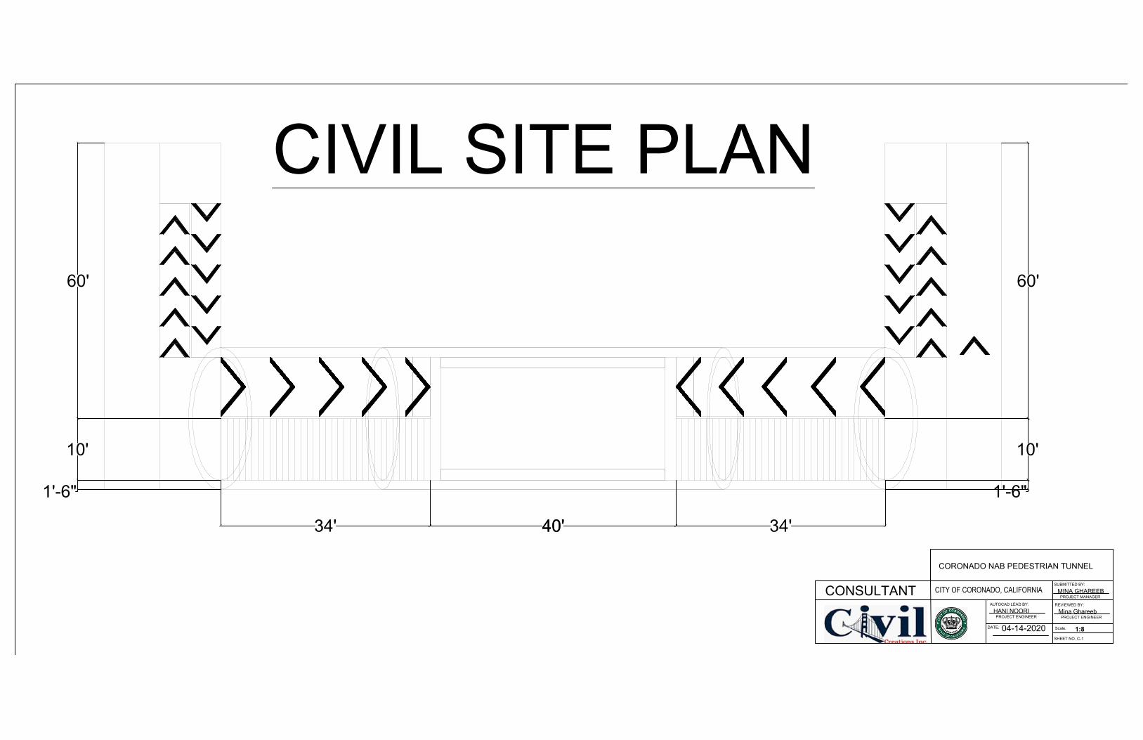
10'
60'
1'-6"
34'40'
CIVIL SITE PLAN
CONSULTANT
CORONADO NAB PEDESTRIAN TUNNEL
CITY OF CORONADO, CALIFORNIA
SUBMITTED BY:
MINA GHAREEB
PROJECT MANAGER
REVIEWED BY:
Mina GhareebPROJECT ENGINEER
SHEET NO. C-1
DATE:
AUTOCAD LEAD BY:
HANI NOORI
PROJECT ENGINEER
Scale.
04-14-20201:8
10'
60'
1'-6"
34' 40'

SIDE VIEW
CONCRETE BED
4'
8'
23'
PLAN
FRONT VIEWCONSULTANT
CORONADO NAB PEDESTRIAN TUNNEL
CITY OF CORONADO, CALIFORNIA
SUBMITTED BY:
MINA GHAREEB
PROJECT MANAGER
REVIEWED BY:
AYA ALABOOSI
PROJECT ENGINEER
SHEET NO. C-2
DATE:
AUTOCAD LEAD BY:
HANI NOORI
PROJECT ENGINEER
Scale.04-14-2020 1:8
TUNNEL
PROFILE &
FOUNDATION
108' 19'19'
87'-10
1
16
" 19'19'
19' 35'22'

SILVER STRAND ROAD
TA
RA
WA
R
OA
D
PURPOSED TUNNEL
SITE
PURPOSED BUS
STOP
RE
ND
OV
A R
OA
D
+10'
PS-N2
N-IN 155
PS-N2
PS15-PS8 18"DIP
15" VCP
V8
CT-IN318
CT-IN320
CT-IN319
CT-IN321
18"
18"
18"
18"
M
PS
P
S
8
1
5
"
V
C
P
12" VCP
MH 461,12.1'
MH 461,12.1'
MH 461,12.1'
MH 461,12.1'
GRADING PLAN
SITE WATER WAY
8" DIA OR
GREATER
LEGENDS
CONSULTANT
CORONADO NAB PEDESTRIAN TUNNEL
CITY OF CORONADO, CALIFORNIA
SUBMITTED BY:
MINA GHAREEB
PROJECT MANAGER
REVIEWED BY:
MUSTAFA RASHEEDPROJECT ENGINEER
SHEET NO. C-3
DATE:
AUTOCAD LEAD BY:
LARA AL ISOOPROJECT ENGINEER
Scale.
04-22-2020 1:8
CONTOUR LINE
STORM WATER
PIPE
SEWERAGE
MANHOLE
STORM WATER
MANHOLE
32° 40' 21" N 117° 10"01"W
32° 40' 22" N 117° 10"02"W
32° 40' 23" N 117° 10"03"W
32° 40' 24" N 117° 10"05"W
32° 40' 25" N 117° 10"06"W
32° 40' 25" N 117° 10"06"W
-12'-0"
STORM WATER
INLET (PRIVATE)
SEWER VENT
STORM GRAVITY
MAIN (PRIVATE)
LEVELS BETWEEN
CONTOURS IS 6"

P
S
-
N
2
N
-
I
N
1
5
5
P
S
-
N
2
C
T
-
I
N
1
6
1
T
A
R
A
W
A
R
O
A
D
S
I
L
V
E
R
S
T
R
A
N
D
B
L
S
T
R
A
N
D
W
Y
P
S
1
5
-
P
S
8
1
8
"
D
I
P
1
5
"
V
C
P
V
8
C
T
-
I
N
3
1
8
C
T
-
I
N
3
2
0
C
T
-
I
N
3
1
9
C
T
-
I
N
3
2
1
1
8
"
1
8
"
1
8
"
1
8
"
R
E
N
D
O
V
A
R
D
M
P
S
P
S
8
1
5
"
V
C
P
1
2
"
V
C
P
M
H
4
6
1
,
1
2
.
1
'
M
H
4
6
1
,
1
2
.
1
'
CITY OF CORONADO
WASTE WATER & STORM WATER MAP
BOOK
WASTE WATER
SYSTEM
CLEAN WATER OUT
SEWER DEAD END
SEWER PUMP STATION
PS
SEWER PUMP STATION (PRIVATE)
PS
SEWER MANHOLE
SEWER MANHOLE (PRIVATE)
SEWER METERING STATION
M
SEWER GRAVITY MAIN
SEWER GRAVITY MAIN (AB)
SEWER FORCE MAIN
SEWER GRAVITY MAIN (PRIVATE)
SEWER FORCE MAIN (PRIVATE)
STORM WATER
SYSTEM
STORM WATER HOLE
STORM WATER HOLE (PRIVATE)
STORM WATER INLET
STORM WATER INLET (ABANDONED)
STORM WATER INLET (PRIVATE)
STORM WATER OUTLET
STORM WATER OUTLET (PRIVATE)
SEWER VENT
STORM GRAVITY MAIN
STORM GRAVITY MAIN (AB)
STORM GRAVITY MAIN (PRIVATE)
STORM FORCE MAIN
STORM PUMP STATIONPS
STORM DIVERTER
STORM DIVERTER
PARCEL BOUNDARY601
(AB) = ABANDONED
(PRIVATE) - SYSTEM ID
CT - CAL TRANS HD - HOTEL DEL PT - PORT
L - LOEWS N - NAVY
SH - SHORES ST - STATE
M
H
4
6
1
,
1
2
.
1
'
M
H
4
6
1
,
1
2
.
1
'
CONSULTANT
CORONADO NAB PEDESTRIAN TUNNEL
CITY OF CORONADO, CALIFORNIA
SUBMITTED BY:
MINA GHAREEB
PROJECT MANAGER
REVIEWED BY:
AYAT ALOBIDIPROJECT ENGINEER
SHEET NO. C-4
DATE:
AUTOCAD LEAD BY:
Mustafa RasheedPROJECT ENGINEER
Scale.
04-16-2020 1:8
UTILITY PLAN

SIL
VE
R S
TR
AN
D R
OA
D
SIL
VE
R S
TR
AN
D
RO
AD
EX
CA
VA
TIO
N
PU
RP
OS
ED
BU
S
ST
OP
TA
RA
W
A R
OA
D
DE
MO
LIS
H
TR
UC
K L
OA
DIN
G A
RE
A
OF
FIC
E T
RA
ILE
R
DU
MP
SIT
E
W
OR
KIN
G A
RE
A D
UR
ING
CO
NS
TR
UC
TIO
N
EQ
UIP
ME
NT
TR
AIL
ER
LA
Y D
OW
N A
RE
A
S-7
5 R
OA
D
FE
NC
E
FE
NC
E
FE
NC
E
FE
NC
E
SIL
T F
EN
CE
BIO
FIL
TE
R
ST
RE
ET
SW
EE
PIN
G
BIO
FIL
TE
R
BIO
FIL
TE
R
BIO FILTER
FENCE
SILT FENCE
LEGENDS
CONSULTANT
CORONADO NAB PEDESTRIAN TUNNEL
CITY OF CORONADO, CALIFORNIA
SUBMITTED BY:
MINA GHAREEB
PROJECT MANAGER
REVIEWED BY:
Lara Al IssoPROJECT ENGINEER
SHEET NO. C-5
DATE:
AUTOCAD LEAD BY:
Mustafa RasheedPROJECT ENGINEER
Scale.
EROSION CONTROL PLAN
04-19-2020 1:8
MA
IN H
OLE
S
CONTOUR LINE

CONSULTANT
CORONADO NAB PEDESTRIAN TUNNEL
CITY OF CORONADO, CALIFORNIA
SUBMITTED BY:
MINA GHAREEB
PROJECT MANAGER
REVIEWED BY:
AYA ALABOOSI
PROJECT ENGINEER
SHEET NO.C-6
DATE:
AUTOCAD LEAD BY:
HANI NOORI
PROJECT ENGINEER
Scale.
SILVER STRAND ROAD
TA
RA
WA
R
OA
D
CURRENT BUS
STOP
DEMOLISH PLAN
04-14-2020
TREES &
BUSHES
1:8

CONSULTANT
CORONADO NAB PEDESTRIAN TUNNEL
CITY OF CORONADO, CALIFORNIA
SUBMITTED BY:
MINA GHAREEB
PROJECT MANAGER
REVIEWED BY:
AYA AL ABOOSIPROJECT ENGINEER
SHEET NO. C-7
DATE:
AUTOCAD LEAD BY:
MINA GHAREEBPROJECT ENGINEER
Scale.
04-18-2020
1:8
17'1'-6"
45° 45°
45°45°
R 10'
1'-6"
REINFORCE CONCRETE
LINING
WATER PROOF
CONCRETE LINING
#12 @ 6"C/C
CONCRETE PAVEMENT
COMPACTED
AGGREGATE
ASPHALT COURSE
8" DRAINAGE
PIPE
CONSTRUCTION
JOINT WITH KEY
REINFORCE
CONCRETE
ASPHALT COURSE
#12 @ 6"C/C
8" DRAINAGE
PIPE
COMPACTED
AGGREGATE
STRUCTURAL PLAN AND REINFORCEMENTCONCRETE OF THE TUNNEL
DETAIL
1
CONCRETE
PAVEMENT
WATER PROOF
· SPACING= 6"
· INNER RADIUS =8'-6"
· OUTER RADIUS =10'-0"
R 8'-6"
· SPACING OF REBAR
S= 0.60^2
· CONCRETE f'c=4.01ksi
· REINFORCING STEEL
f'y=60.0ksi , Es=2900
· REINFORCING STEEL
f'y=60.0ksi , Es=2900
· AREA OF SINGLE REBAR
As-bar=0.6IN^2
· NORMAL WIGHT OF
REINFORCEMENT
CONCRETE Wc=0.150kcf
· STRIP Wstrip=1ft
MATERIAL
SPECIFICATION &
DRAWING DETAIL

SECTION
8'
21'-8"
RAMP
RAMP
STAIRS
STAIRS
TUNNEL
SIDE WALK
SIDE WALKSIDE WALK
SIDE WALK
9'10'
9' 10'
10'
CONCRETE BED
CONCRETE BED
20'
20'
1'
CROSS
SECTION
#12 @ 6"C/C
#12 @ 6"C/C
SHEAR
WALLS
TOP &
BOTTOM
SLABS
1'
CONSULTANT
CORONADO NAB PEDESTRIAN TUNNEL
CITY OF CORONADO, CALIFORNIA
SUBMITTED BY:
MINA GHAREEB
PROJECT MANAGER
REVIEWED BY:
HANI NOORIPROJECT ENGINEER
SHEET NO. C-8
DATE:
AUTOCAD LEAD BY:
AYA AL ABOOSIPROJECT ENGINEER
Scale.
04-18-20201:8
TUNNEL SECTION
& DETAIL

CO
NS
ULT
AN
T
CO
RO
NA
DO
NA
B P
ED
ES
TR
IAN
TU
NN
EL
SU
BM
ITT
ED
BY
:
MIN
A G
HA
RE
EB
PR
OJE
CT
MA
NA
GE
R
RE
VIE
WE
D B
Y:
AY
A A
LA
BO
OS
IP
RO
JEC
T E
NG
INE
ER
.SH
EE
T N
O C
-8
DA
TE
:
AU
TO
CA
D L
EA
D B
Y:
HA
NI N
OO
RI
PR
OJE
CT
EN
GIN
EE
R
Sca
le.
04-1
9-2
020
1:8
276 #12 @ 6"C/C
276 #12 @ 6"C/C
PL
AN
40 #
12 @
6"C
/C40 #
12 @
6"C
/C
#12 @
6"C
/C# 3
@ 6
"C/C
16"
SE
CT
ION
A-A
A A
SLA
B R
EIN
FO
RC
EM
EN
T
PLA
N
CLE
AR
CO
VE
R 1
"
MA
TE
RIA
L S
PE
CIF
ICA
TIO
N &
DR
AW
ING
DE
TA
IL
·S
PA
CIN
G= 6
"
·S
PA
CIN
G O
F R
EB
AR
S= 0
.60^2
·C
ON
CR
ET
E f'c
=4.0
1ksi
·R
EIN
FO
RC
ING
ST
EE
L f'y
=6
0.0
ksi ,
Es=2900
·R
EIN
FO
RC
ING
ST
EE
L f'y
=6
0.0
ksi ,
Es=2900
·A
RE
A O
F S
ING
LE
RE
BA
R
As-b
ar=
0.6
IN^2
·N
OR
MA
L W
IGH
T O
F
RE
INF
OR
CE
ME
NT
CO
NC
RE
TE
Wc=
0.1
50kcf
·S
TR
IP W
strip
=1ft
·H
EIG
HT
OF
WA
LL H
w=1
0'
·S
EC
TIO
N H
EIG
HT
OF
TO
P S
LA
B
H=1
6"
·S
EC
TIO
N W
IDT
H O
F T
OP
SL
AB
=12"
ODUCED BY AN AUTODESK STUDENT VERSION
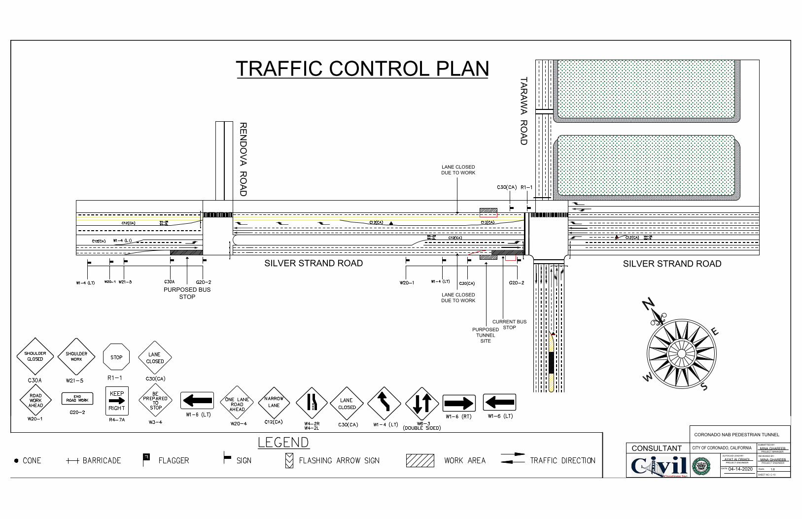
CONSULTANT
CORONADO NAB PEDESTRIAN TUNNEL
CITY OF CORONADO, CALIFORNIA
SUBMITTED BY:
MINA GHAREEB
PROJECT MANAGER
REVIEWED BY:
MINA GHAREEBPROJECT ENGINEER
SHEET NO. C-10
DATE:
AUTOCAD LEAD BY:
AYAT ALOBIADIPROJECT ENGINEER
Scale.
SILVER STRAND ROADSILVER STRAND ROAD
TA
RA
WA
R
OA
D
PURPOSED
TUNNEL
SITE
PURPOSED BUS
STOP
RE
ND
OV
A R
OA
D
CURRENT BUS
STOP
TRAFFIC CONTROL PLAN
04-14-2020
LANE CLOSED
DUE TO WORK
LANE CLOSED
DUE TO WORK
1:8