Embed Size (px)
Citation preview

1
Transmission Strategies for ThroughputMaximization in High Speed Train Communications:
From Theoretical Study to Practical AlgorithmsAyotunde O. Laiyemo, Student Member, IEEE, Harri Pennanen, Member, IEEE,
Pekka Pirinen, Senior Member, IEEE, and Matti Latva-aho, Senior Member, IEEE
Abstract—This paper focuses on improving the downlinkthroughput of the base station to train communication link in ahigh speed train (HST) scenario. First, we provide a theoreticalstudy of the throughput maximization problem in a single-cell MIMO-OFDM train scenario with and without cooperationamong carriages. The aim is to give fundamental insight into theproblem rather than providing practically realizable algorithms.The theoretical study suggests that it is highly advantageousto exploit the size of the train by increasing the number ofantennas, and further allowing the carriages to cooperate. Inthe practical system level study, we propose two low complexityMIMO-OFDM transmission schemes, which are based on simpleantenna selection methods with spatial multiplexing. The mainidea is to select the best transmit antennas among differentantenna combinations by comparing their estimated throughputperformances. The simulation results show that the proposedalgorithms outperform LTE-based dynamic rank transmissionschemes in terms of throughput and computational load inpractical HST scenarios. Unlike the exhaustive search type ofdynamic transmission schemes, our simple algorithms are alsoapplicable to large antenna arrays. In conclusion, large antennaarrays with simple antenna selection and spatial multiplexingtransmission strategies seem potential solutions to significantlyimprove the throughput of the base station to train link in HSTscenarios.
Index Terms—Antenna selection, high mobility communica-tions, MIMO-OFDM, spatial multiplexing, system level simula-tion.
I. INTRODUCTION
THE increasing interest in the deployment of high speedtrains (HSTs) in many parts of the world has evoked
the need to provide high quality wireless communicationservices to onboard users. Following the recent trend in cel-lular communications, the HST passengers also need accessto bandwidth hungry applications. However, providing highdata rates and good quality of service (QoS) to passengers
This research was supported by the Finnish Funding Agency for Tech-nology and Innovation (TEKES), Nokia Networks, Anite Telecoms, Huawei Technologies, Broadcom Communications Finland, and Elektrobit Wireless Communications.
The authors are with the Centre for Wireless Communications, University of Oulu, P.O. Box 4500, 90014 University of Oulu, Finland. (e-mail: [email protected])
in the presence of rapidly varying channel conditions is achallenging task [1]. An effective way to increase data rateis the use of multiple-input multiple-output (MIMO) and or-thogonal frequency division multiplexing (OFDM) techniques[2]. However, to achieve the available performance gains,knowing the channel characteristics is highly important. Hence,to ensure reliable communication for passengers, knowledgeabout the different types of high speed railway environmentsis required to ensure proper communication network planningand to optimize transmitter and receiver designs. The HSTrailway environment possesses distinctive propagation char-acteristics and design opportunities. Hence, the transmissionschemes tailored for the conventional cellular communicationenvironments are likely to be suboptimal. The propagationcharacteristics of the railway environment have been observedin a number of studies through channel measurements andanalyses of such environments [3]–[8]. Channel sounding forHST railway environment was examined in [9], where theauthors’ focus was on HST MIMO and coordinated multipoint(CoMP) channel measurements.
With the knowledge of the channel properties, providingreliable communication for passengers still remains a challengedue to the fast moving and well shielded carriages whichcauses severe Doppler frequency shift, high penetration loss,outdated channel feedback information, frequent and large han-dover processes, increased power consumption of passengers’mobile equipments and low data rates [10]. To overcome someof these problems, different authors have proposed variousways of efficiently providing wireless services to passengers[11]–[15]. The most promising concept is the use of a two hopnetwork architecture, where the communication link is dividedinto a base station to train link (the backhaul link) and a trainto onboard link (the access link). This network architectureenhances cellular coverage since vehicular penetration loss(VPL), which can be as high as 23 dB [16], can be eliminated.Also large simultaneous group handover processes and thepassengers’ high power consumption are significantly reducedwith the two hop network architecture. Further studies in [17]and [18] have shown that even though there is a performancegain with the network architecture compared to direct trans-mission, there are still challenges and the main bottleneck isthe backhaul link.
Studies in [19] try to tackle the frequent handovers expe-rienced over the backhaul link, with the use of two antennasmounted at the front and rear of the train. When the train

2
moves towards the cell edge, the front antenna executeshandover while the rear antenna is still connected to the servingbase station (BS). In [20], the problem of high handover failureprobability was addressed with the use of coordinated multiplepoint transmission concept to achieve diversity gain with theHST receiving signals from two adjacent BSs when movingthrough overlapping areas.
MIMO spatial multiplexing in high speed railway com-munications has been studied in [21]–[23]. Studies in [21]analyzed the achievable MIMO capacity for high speed trainwith multiple antennas based on 3-D modeling of line-of-sight(LOS) channel. The authors show that spatial multiplexinggains can be achieved with a proposed multi-group multi-antenna (MGMA) scheme, in which the capacity gain can beachieved by adjusting the weights among the MGMA arrays.On the other hand, the approach in [22], is to reconstruct thechannel through the method of principal component analysissuch that the correlation in the railway channel matrix isreduced. Hence, spatial multiplexing gains can be achieved.Reference [23] employs the selection of the appropriate an-tenna spacing to ensure that the channel response is not rankdeficient. The impact of imperfect channel state information(CSI) on high mobility systems, examined in [24], shows thataccurate estimation and tracking of the fast time-varying fadingare critical to reliable operation. Also studies in [25] haveshown that in many mobile scenarios, the upper bound ofthe achievable data rate is mainly defined by the feedbackdelay of the CSI. Due to the outdated and imperfect CSI, thethroughput gains provided by conventional precoding methodsmay be marginal or even non-existent. Conceptually simpleantenna selection methods implemented at the transmitter havebeen studied with different receive antenna combinations andtransmission schemes [26]–[30]. The performance of transmitantenna schemes relies on the required feedback of informationon selected antenna index/indices from the receiver to the BS.However, most of these studies only consider single antennaselection. In [28], multiple transmit antenna selection forspatial multiplexing was achieved by considering the detectionorder of an ordered successive interference cancellation (SIC)receiver with power control per antenna. Antenna selectionfor spatial multiplexing for practically realizable receivers wasstudied in [29] and [30]. The number of transmitted streamsin these studies were fixed and a subset among all possibletransmit antennas was chosen.
The aforementioned antenna selection schemes are designedfrom the perspective of conventional cellular systems. How-ever, there are two major differences between an HST system(considering the BS to train backhaul link) and a conventionalcellular system. The number of receiving antennas and thespeed of the receiver can be both notably higher in theHST scenario. These characteristics suggest that large antennaarrays can be used to improve the throughput performance ofan HST communication system via the achieved multiplexinggain. Moreover, the size of the train can be exploited to easethe spatial separability of the transmitted signals at the receiverside. Due to the high speed of the train, conventional precodingmethods may not provide any practical performance gains.Instead, simpler spatial multiplexing methods with antenna
selection schemes could be of practical interest. However,with large antenna arrays, adaptive transmission schemes mayrequire extensive computational load, especially if the designis based on the exhaustive search type of adaptivity. The mainaim of this paper is to address the aforementioned possibilitiesand challenges, and to study how the throughput performancecan be increased in a realistic HST communication scenario.The contributions of this paper are introduced next.
In this paper, we focus on maximizing the downlinkthroughput of the BS to train link. Our analysis is built onMIMO-OFDM techniques in theoretical link level and practicalsystem level scenarios. We first consider the throughput max-imization problem in a theoretical single-cell MIMO-OFDMtrain scenario, and describe two convex optimization basedtransmission strategies. The objective of the theoretical study isto give fundamental insight into the throughput maximizationproblem in a simple train scenario rather than providingpractically realizable transmission algorithms. The theoreticalresults demonstrate that notable gains can be obtained whenthe number of antennas is increased at the BS and train, and thecarriages of the HST cooperate with each other. In the practicalanalysis, we first apply and evaluate the LTE-based closed-loop and open-loop precoding with fixed and dynamic ranktransmission schemes to a realistic system level HST scenario.Then we compare its performance with the exhaustive searchscheme. After which we propose two low complexity transmis-sion schemes that are based on simplified antenna selectionmethods with spatial multiplexing. These practical schemescan easily fit into the LTE-Advanced transmission structure. Inthe algorithms, the best transmit antennas are selected amonga set of antenna combinations by comparing their estimatedthroughput at the train, and sending the information to the BSvia a feedback link. The key idea of the algorithms is to provideperformance close to the exhaustive search method, but withsignificantly reduced computational load (i.e., the number ofthroughput calculations). The simulation results imply that apromising practical solution to notably increase the backhaullink throughput in an HST scenario is to use low complexityantenna selection and spatial multiplexing techniques, andhave large antenna arrays at the BSs and train. The maincontributions of this paper are summarized as follows:• Theoretical study of the throughput maximization opti-
mization problem in a single-cell MIMO-OFDM trainscenario with and without cooperation among carriages.
• Practical low complexity MIMO-OFDM transmissionschemes, which are based on simple antenna selectionmethods with spatial multiplexing.
• Practical system-level performance and complexity eval-uation of the proposed transmission schemes and LTE-based open-loop and closed-loop precoding methods.
The rest of this paper is organized as follows. In SectionII, the system models for both the theoretical and practicalscenarios are introduced. The throughput maximization algo-rithms for both cooperative and non-cooperative train scenariosare described for the theoretical system in Section III. LTE-based transmission strategies are applied to an HST scenario inSection IV. In Section V, the proposed low complexity antennaselection and spatial multiplexing methods are introduced.

3
Section VI describes the simulators used for both theoreticaland practical scenarios. The simulation results are presentedin Section VII. A brief discussion on the simulation results ispresented in Section VIII and the conclusion is provided inSection IX.
The following notations are carried out in this paper. Vectorsand matrices are represented by boldface lower and upper caseletters, respectively. The conjugate transposes of a matrix Hand a vector h are denoted as HH and hH , respectively.
II. SYSTEM MODEL
We consider a train communication scenario focusing onthe BS to train link. The train has multiple carriages, eachequipped with a single moving relay node (MRN). The numberof MRNs is denoted by M . Each MRN has an external antennaarray with Nr receive antennas that are assumed to be evenlyspaced along the length of the corresponding carriage. Thenumber of transmit antennas at the BS is Nt. The systemsupports MIMO-OFDM communications. Frequency domainis divided into C subcarriers. The downlink communicationsbetween the BS and the train is analyzed in simple single-cell and realistic multi-cell systems to reflect theoretical andpractical scenarios, respectively. For the clarity of presentation,separate signal models are presented for both scenarios. In allcases, we assume linear transmit/receive design strategies.
A. Theoretical Single-Cell Scenario
With a BS connected to M MRNs, two modes of oper-ation are derived. In non-cooperative mode, each MRN isperforming reception independently and there is no form ofcooperation among the MRNs. In cooperative mode, the MRNscan cooperate with each other and act as a large receive antennaarray in order to aid data reception.
1) MRN Non-Cooperative Mode: The BS is transmittingdata to all MRNs simultaneously while each MRN is per-forming reception independently at the train. This is illustratedin Fig. 1 without the connecting link among the MRNs.This scenario is conceptually similar to a point-to-multipointMIMO-OFDM system. The downlink received signal vectoryc,m ∈ CNr at the mth MRN for the cth subcarrier is given by
yc,m =
M∑m=1
Lm∑l=1
Hc,mmc,m,lsc,m,l + nc,m (1)
where Hc,m ∈ CNr×Nt is the channel matrix between theBS and the mth MRN, mc,m,l ∈ CNt is the unnormal-ized precoding vector for the lth stream of the mth MRN,sc,m,l ∈ C denotes the corresponding data symbol and nc,m ∼CN (0, N0INr ) is the additive complex white Gaussian noisevector with zero mean and N0 variance per element. Thenumber of data streams given to the mth MRN is denotedby Lm. The total transmit power of the BS is given byP =
∑Cc=1
∑Mm=1
∑Lm
l=1 ∥mc,m,l∥22. The received signal tointerference plus noise ratio (SINR) of the lth stream at themth MRN can be written as
Γc,m,l =|wH
c,m,lHc,mmc,m,l|2
∥wc,m,l∥2N0 +M∑q=1
Lq∑i=1
(i,q)=(l,m)
|wHc,m,lHc,mmc,q,i|2
,
(2)
where wc,m,l ∈ CNr denotes the receive filter for the lth streamof the mth MRN.
2) MRN Cooperative Mode: The BS serves the whole trainsimultaneously and all MRNs can jointly perform reception,as depicted in Fig. 1. Due to cooperation among the MRNs,
MRN 1 MRN 2
BS
MRN M
Fig. 1: Single-cell train scenario.
this scenario can be conceptually interpreted as a point-to-pointMIMO-OFDM system. The signal model simplifies since allMRNs can be considered as a single receiver and the index ofMRNs can be omitted. The downlink received signal vectoryc ∈ CMNr for the cth subcarrier can be expressed as
yc =L∑
l=1
Hcmc,lsc,l + nc (3)
where mc,l ∈ CNt denotes the precoding vector of thelth stream, sc,l ∈ C is the corresponding data symbol andnc ∈ CMNr is the additive complex white Gaussian noisevector. The total number of data streams transmitted to allM MRNs is given by L ≤ min (Nt,MNr).The channelmatrix from the BS to the whole MRN system is denotedby Hc = [HH
c,1 . . .HHc,m . . .HH
c,M ]H ∈ CMNr×Nt . The totaltransmit power is expressed as P =
∑Cc=1
∑Ll=1 ∥mc,l∥22.
Given the receive filter wc,l ∈ CMNr over all MRNs, the SINRfor the cth subcarrier on the lth stream can be expressed as
Γc,l =|wH
c,lHcmc,l|2
∥wc,l∥2N0 +
L∑i=1i =l
|wHc,lHcmc,i|2
. (4)
B. Practical Multi-Cell ScenarioFig. 2 provides a schematic representation of the HST in
a multi-cell network configuration. The system consists oftrisector antenna sites, where each sector forms a cell. The totalnumber of cells in the system is B. For the ease of presentation,we refer to sectors as BSs in the rest of the paper. Each MRNcan only have a direct connection to a single BS at a time.

4
MR
N2
MR
N8
MRN 1 MRN 2
BS
X2
BS
Trisector BS
Ground UsersMRN M
Fig. 2: Multi-cell train scenario.
In other words, a single MRN cannot be served by multipleBSs simultaneously. Different MRNs of the same HST can beconnected either to the same BS or different BSs. Thus, anHST with multiple MRNs can be served by a single BS ormultiple BSs, depending on the position of the HST in thenetwork layout. The number of MRNs jointly associated toBS b is denoted by Mb. Interference from onboard users tothe MRNs’ external antennas is omitted since half duplexingoperation is assumed. We assume perfect synchronization sincefrequency offsets caused by the velocity of the HST canbe compensated for [31] at different positions [32] alongthe predictable route despite the fast time varying Dopplershift. We also assume that Q ground macro users with lowmobility are randomly distributed in the multi-cell system andare therefore scheduled alongside the MRNs. Transmissionsto ground users are considered as interference. We modelthe fast fading channel based on a geometry-based stochasticmodeling approach, which allows the creation of an arbitrarydouble direction radio channel independent of any antennaconfiguration. Other channel parameters are based on statisticaldistributions extracted from real channel measurements andthey are obtained stochastically [33]. More details on the usedchannel model are given in Section VI.
In this scenario, we consider MIMO-OFDM system op-erating in frequency division duplexing (FDD) mode andassuming that the MRNs served by the same BS can cooperate.The number of links formed depends on the number of BSsassociated with the HST at every time instance. The MRNscoordinate within themselves and form groups based on MRNsassociating with the same BS and each group formed cooper-ates as a single receive antenna array to establish a backhaullink. For clarity, we assume that the whole train is served bya single BS in the following signal model representation (i.e.,Mb = M ). The received signal vector yc ∈ CMNr for theMIMO transmission for subcarrier c can be expressed as
yc = HcMcsc +K∑
k=1
Hc,kMc,k sc,k + nc (5)
where Hc ∈ CMNr×Nt is the channel matrix between the serv-ing BS and the entire MRN system, Mc = [mc,1 . . .mc,L] ∈
CNt×L is the unnormalized transmit precoding matrix forthe desired data streams, sc ∈ CL is the correspondingtransmit signal vector and nc ∈ CMNr is the additive whiteGaussian noise vector. Note that Mc can be expressed asMc = P1/2
c Fc, where Fc = [fc,1 . . . fc,L] is the normalizedprecoding matrix and Pc = diag(Pc,1 . . . Pc,L) consists ofthe powers allocated to each L streams. Hc,k ∈ CMNr×Nt ,Mc,k = [mc,1 . . . mc,Lk
] ∈ CNt×Lk , and sc,k ∈ CLk are thechannel matrix from interfering BS k to the MRN system, theprecoder matrix used at BS k to transmit Lk (interfering) datastreams and the corresponding signal vector. The total numberof the interfering BSs is denoted by K.
The throughput optimal linear minimum mean square error(MMSE) filtering is applied at the receiver. The MMSE filterWc = [wc,1 . . . wc,L] ∈ CMNr×L is obtained by minimizingthe mean square error defined as E
[∥sc − WH
c yc∥2], where
Wc = (HcMcMHc H
H
c + Rc)−1HcMc , (6)
where Hc and Rc are the estimates of the channel matrixHc and the interference plus noise covariance matrix Rc,respectively. The matrix Rc is given by
Rc =
K∑k=1
Hc,kMc,kMH
c,kHH
c,k +N0IMNr . (7)
The SINR of transmission stream l for subcarrier c at theoutput of the MMSE receiver is given by
Γc,l =|wH
c,lHcmc,l|2L∑
j=1,j =l
|wHc,lHcmc,j |2 + wH
c,lRcwc,l
. (8)
III. PRECODING SCHEMES FOR THEORETICAL SCENARIO
In this section, the throughput maximization problem isformulated for a downlink single-cell MIMO-OFDM trainsystem with and without cooperation between MRNs. It isassumed that the channel is known at the BS and the MRNs.We propose precoding schemes that maximize the throughputgiven the aforementioned assumptions.
A. MRN Non-Cooperative ModeIn order to maximize throughput, the optimization problem
of sum rate maximization under total transmit power constraintcan be formulated as follows
maximizemc,m,l,wc,m,lC,M,L
c=1,m=1,l=1
C∑c=1
M∑m=1
L∑l=1
log (1 + Γc,m,l)
subject toC∑
c=1
M∑m=1
L∑l=1
∥mc,m,l∥22 ≤ P.
(9)
Note that a positive weighting factor can be added to theobjective function of (9) in order to maintain a certain degree offairness among the MRNs, and possibly reflect the number ofonboard users in each carriage required to be served. Problem(9) is non-convex, and thus, it cannot be solved in its currentform. However, (9) can be reformulated and approximated

5
to obtain an efficient (sub-optimal) solution where the ob-jective function (i.e., sum rate) converges. However, globaloptimality cannot be guaranteed due to the non-convexity ofthe original problem. The proposed algorithm is an extensionof the approach in [34] to a multi-carrier system. The ideaof the algorithm is to divide (9) into precoder and receivefilter design problems, which are solved alternatingly until theobjective function converges. In other words, the precoders areoptimized while the receive filters are fixed, and vice versa.The optimal receive filters per-subcarrier are obtained by usingthe linear MMSE criterion. This is given by
wc,m,l =
(M∑
m=1
L∑l=1
Hc,mmc,m,lmHc,m,lH
Hc,m+
INrN0
)−1
Hc,mmc,m,l.
(10)
In order to solve the precoders, the sum rate maximizationproblem can be reformulated as a sum log-mean square error(MSE) minimization problem, expressed as
minimizemc,m,lC,M,L
c=1,m=1,l=1
C∑c=1
M∑m=1
L∑l=1
log (ϵc,m,l)
subject toC∑
c=1
M∑m=1
L∑l=1
∥mc,m,l∥22 ≤ P
(11)
where ϵc,m,l is the MSE at the mth MRN for the cth subcarrieron the lth stream and the relation between the MSE and SINR[35] is expressed as
ϵ−1c,m,l = 1 + Γc,m,l. (12)
With fixed receive filters, the sum log-MSE minimizationproblem is still a non-convex problem. Therefore, the transmitprecoder design is reformulated using difference of convexfunction program (DCP) by introducing an auxiliary constraint
ϵc,m,l ≤ 2−tc,m,l (13)
where the auxiliary variable tc,m,l is assumed to be suchthat 2tc,m,l ≥ 1. This implies that the domain of the con-vex MSE upper bounding function 2−tc,m,l is in the rangeof possible MSE values, i.e., between 0 and 1. Note thatalso other exponential functions are applicable if they satisfythese assumptions. Applying (13) and relaxing the objectiveaccordingly, the resulting problem is given by
maximizemc,m,l,tc,m,lC,M,L
c=1,m=1,l=1
C∑c=1
M∑m=1
L∑l=1
tc,m,l
subject toC∑
c=1
M∑m=1
L∑l=1
∥mc,m,l∥22 ≤ P
ϵc,m,l ≤ 2−tc,m,l ∀c,m, l.
(14)
The relaxation is tight since the inequality constraints achievethe optimal solution with equality. Problem (14) is still
non-convex. Next, we apply successive convex approxima-tion (SCA) method to approximate (14), and then, we it-eratively solve the resulting convex problems such that theobjective function converges. Now, a linear approximation off(tc,m,l) = 2−tc,m,l is found by taking the first order Taylorseries approximation at a point t(i)c,m,l. This is expressed as
f(tc,m,l, t(i)c,m,l) = f(t
(i)c,m,l) + (tc,m,l − t
(i)c,m,l)f
′tc,m,l
(t(i)c,m,l)
= −a(i)c,m,ltc,m,l + b
(i)c,m,l
(15)
where f ′ denotes the partial derivative and
a(i)c,m,l = ln(2)2−t
(i)c,m,l , b
(i)c,m,l = 2−t
(i)c,m,l
(1 + ln(2)t
(i)c,m,l
).
(16)
As a result, we can formulate the following optimizationproblem at the ith iteration of the SCA method for fixedt(i)c,m,l
C,M,Lc=1,m=1,l=1
maximizemc,m,l,tc,m,lC,M,L
c=1,m=1,l=1
C∑c=1
M∑m=1
L∑l=1
tc,m,l
subject toC∑
c=1
M∑m=1
L∑l=1
∥mc,m,l∥22 ≤ P
ϵc,m,l ≤ −a(i)c,m,ltc,m,l + b
(i)c,m,l.
(17)The next point of approximation t
(i+1)c,m,l can be found by using
a line search method in [34]. The SCA-based convex problemswith the updated approximation points are repeatedly solved.The objective value converges since it increases monotonicallyat each iteration of the SCA method and the receive filterupdate via the MMSE. The complete method is described inAlgorithm 1.
Algorithm 1 Precoder and receive filter design for MRN non-cooperative mode.
1: Set i = 0. Initialize precoders and point of approximationsmc,m,l, t
(0)c,m,l
C,M,Lc=1,m=1,l=1.
2: repeat3: Compute receive filters wc,m,lC,M,L
c=1,m=1,l=1 using (10).4: repeat5: Compute SCA values a(i)c,m,l, b
(i)c,m,l
C,M,Lc=1,m=1,l=1 using
(16).6: Compute precoders mc,m,lC,M,L
c=1,m=1,l=1 using (17).7: Update tc,m,l using line search method.8: i = i+ 1.9: until desired level of convergence.
10: until desired level of convergence.
B. MRN Cooperative ModeTo maximize throughput, well known singular value decom-
position (SVD) and water-filling principles can be exploited.Specifically, we apply SVD to each per-subcarrier channel

6
matrix and use the resulting right singular vectors as precodersand left singular vectors as receive filters. This is writtenmathematically as Hc = UcΛcVH
c , where the columns of Vc ∈CNt×Nt and Uc ∈ CMNr×MNr are the right and left singularvectors, respectively. The diagonal entries of Λc ∈ RMNr×Nt
are the ordered singular values (λc,1, ..., λc,L) of Hc with theremaining entries equal to zero. The optimal power allocationis achieved by extending the MIMO water-filling algorithmin [36] to MIMO-OFDM systems, where the resulting water-filling algorithm is performed over the independent MIMOchannels and subcarriers. This transmission technique is alsocapacity achieving strategy. The overall transmitter-receiverstrategy achieves the channel capacity as follows
C =C∑
c=1
L∑l=1
log
(1 +
P ∗c,l|uH
c,lHcvc,l|2
N0
), with
P ∗c,l =
(µ− N0
|uHc,lHcvc,l|2
)+ (18)
where the so-called water-level µ is chosen to satisfy the totalpower constraint, i.e.,
∑Cc=1
∑Ll=1 P
∗c,l = P . Symbols vc,l and
uc,l denote the lth column of Vc and Uc, respectively.
IV. LTE PRECODING SCHEMES APPLIED TO HIGH SPEEDTRAIN SCENARIO
This section examines the existing LTE precoding codebookschemes and how we apply them to the HST scenario forperformance evaluation. The type of the codebooks usedand the rationale behind the choice is briefly explained first.Precoding at the BS requires information about the MIMOchannel. The channel information can be obtained via feedbackfrom the MRNs. Unfortunately, the feedback of the channelinformation involves a significant overhead on the uplinkcapacity for most systems, especially on systems with highbandwidth and/or high mobility [37]. Thus, a necessary andpractical solution is the use of limited feedback, where boththe BS and radio terminal share a common codebook. Theradio terminal searches the codebook for vectors/matrices thatcan maximize the overall system performance and the indexof that vector/matrix is fed back to the BS. A combinationof discrete fourier transform (DFT) based codebook [38] andhouseholder (HH) based codebook [39] is adopted by LTEand LTE-A due to its high precoding gain, lower feedbackoverhead, lower complexity and flexible support for variousantenna configurations.
Based on the HH codebook design, we examine the impactof the LTE based closed-loop and open-loop spatial multiplex-ing schemes on the railway network. In the closed-loop spatialmultiplexing scheme, the MRN/receiver estimates the channelfeedback information, which includes the channel qualityindicator (CQI), precoding matrix indicator (PMI), and rankindicator (RI) and feeds back the channel feedback informationto the BS in order to maximize the spectral efficiency. TheCQI value, which is based on the derived SINR, indicates theoptimum modulation and coding scheme (MCS) to be used forthe next transmission. The PMI chooses the optimum precoder
matrix from a predefined codebook and the index of the chosenprecoder matrix is conveyed to the BS. While the RI choosesthe optimum number of layers for MIMO transmissions. Inthe case of the open-loop spatial multiplexing scheme, theestimated channel feedback information includes only the CQIand the RI. The feedback of the PMI is not required, howevera subset of codebook is applied at the BS together with cyclicdelay diversity (CDD). The open-loop pre-coding matrix isdefined as
Fc = Fn[i]DcU (19)where Fn[i] ∈ CNt×L is the ith precoding matrix from thechosen subset of the nth codebook, Dc is a CDD matrix ofsize L×L that changes with the index of the sub-carriers, U isa fixed DFT matrix of size L×L. The CDD Dc and the DFTU matrices are defined for 2, 3, and 4 transmission layers in[40], [41].
The selection criteria for the PMI and RI are based onmaximizing the throughput, which is defined as
Tr,f =
C∑c=1
r∑l=1
log2 (1 + Γc,l) (20)
where the subscript f signifies the selected precoder matrixand r, which can vary from 1 to ≤ min (Nt, Nr), is thenumber of transmission rank/streams selected. The SINR Γc,l
is taken from (8). When fixed rank transmissions are consid-ered r = min (Nt, Nr). The throughput maximizing PMI andRI values for the closed-loop scheme involves an exhaustivesearch through the codebook, which size grows exponentiallywith an increase in the number of transmit antennas. Thesevalues are chosen according to
(r∗, f∗) = arg maxr∈R,f∈B
Tr,f (21)
where r∗ is the selected transmission rank from the setR, which consists of possible transmission ranks, i.e, R =1, ...,min (Nt, Nr). The index f∗ is the chosen precodermatrix from the codebook B, which includes the predefinedset of precoders for different transmission ranks. On the otherhand, the throughput maximizing RI value in the open-loopspatial multiplexing scheme is chosen according to
r∗ = argmaxr∈R
Tr,f (22)
where f is a precoder matrix selected in a predefined anddeterministic way according to (19). It is worth noting thateven if the transmission rank changes, all transmit antennasare always used for data transmissions.
V. PRACTICAL TRANSMISSION SCHEMES BASED ONANTENNA SELECTION AND SPATIAL MULTIPLEXING
In this section, two low complexity transmission schemeswith simplified antenna selection and spatial multiplexing areproposed for the HST scenario. Before a detailed description,the rationale behind these schemes is given. There are twofundamental differences between a HST system (consideringthe BS to train backhaul link) and a conventional cellular sys-tem. The receiver speed and the number of receiving antennascan be both significantly higher in the HST scenario than inthe traditional cellular system. Thus, designing practical trans-mission schemes for the HST scenario requires a change of

7
perspective to start with. In LTE systems, the use of codebook-based precoding schemes can provide improved throughputperformance in conventional cellular scenarios. However, inhigh mobility scenarios, such as HST, the achievable gains inthroughput performance by using precoding may be minimalor even non-existent as compared with transmission strategieswithout precoding, as will be shown via numerical examplesin Section VII. Moreover, the conventional LTE-based dy-namic rank transmissions, where the number of data streamsis adapted to the prevailing channel conditions, are mainlydesigned for mobile users with low number of receivingantennas. Using LTE-based precoding schemes with dynamicrank transmissions, the performance metric is calculated forall different precoder/stream combinations, and the one withthe highest value is selected for the next transmission. This ex-haustive search type of process may require extensive amountof computation since the number of different combinations canbe high, especially while having large antenna arrays also atthe receiver side.
In this respect, we propose two low complexity algorithmsthat are based on spatial multiplexing and simplified antennaselection. The algorithms are less complex and provide im-proved performance as compared with the LTE precodingschemes with dynamic rank transmissions. Furthermore, theselow complexity algorithms are also applicable to the casewhere large number of antennas is used at the transmitterand receiver. The proposed practical transmission schemes areimplemented at the receiver side of a communication linkby utilizing the estimated MIMO channels using cooperativeMRNs at the train. The information on the selected numberand positions of the transmit antennas is fed back to the BS,which then performs data transmission using spatial multi-plexing with the chosen set of antennas. In the used spatialmultiplexing technique, precoding is not used, and each datastream is sent from a single transmit antenna. At the receiverside, each MRN performs the linear MMSE reception. Due tocooperation between the MRNs, all the MRNs connected tothe same BS within a transmission time interval can be seenas a large MMSE receiver.
A. Adaptive Transmission Scheme Based on Two-Phase An-tenna Selection
The first practical algorithm has two phases for a properselection of the transmit antennas. The target of the first phaseis to select an appropriate number of transmit antennas tobe used for the spatial multiplexing transmission. The secondphase aims to select the proper antenna positions for the givennumber of antennas chosen in the first phase. In both phases,the appropriate options are chosen that provide the highestestimated throughput assuming spatial multiplexing transmis-sion. There are different ways to estimate the throughputperformance at the receiver side. Since the MMSE receiveris used, it is logical to calculate post-MMSE throughput byassuming spatial multiplexing transmission, as given by
TNt =C∑
c=1
Nt∑l=1
log2
(1 +
Pc,l||wHc,lhc,l||2
N0 +
Nt∑i =l
Pc,i||wHc,ihc,i||2
), (23)
where wc,l is the MMSE receiver for stream l at subcarrierc, and it is obtained from (6). For the later usage, the MIMOchannel at subcarrier c is denoted by Hc = [hc,1, ..., hc,Nt ].Equation (23) gives the total throughput over the subcarriersand transmission streams. The index Nt denotes the number oftransmit antennas used. Another possible performance metricis pre-MMSE throughput given by
TNt =C∑
c=1
Nt∑l=1
log2
(1 +
Pc,l||hc,l||2
N0 +
Nt∑i =l
Pc,i||hc,i||2
). (24)
Note that (23) is more accurate metric, whereas (24) iscomputationally less complex. It is worthwhile to mentionthat alternative performance metrics than throughput can alsobe used. One such metric can be composed by calculatingreceived signal powers and correlation levels for differentcombinations of antenna counts and positions. This idea isdescribed in [42].
The key idea of the algorithm is to significantly reduce thenumber of combinations, which need to be compared to eachother. This is obtained by selecting only a subset of possiblecombinations to be compared with each other in both phasesof the algorithm. The intuition here is that the most relevantcombinations are chosen for the subsets to be compared witheach other, and the less relevant ones are left out from the com-parison. The sizes of the subsets can be considered as designparameters, and there is a complexity-performance trade-off.Here the complexity refers to computational load, which isdefined as the number of throughput calculations. The largerthe size of the subset is, the better the performance and thehigher the computational load. However, choosing the subsetsproperly the computational load can be significantly reducedwhile providing performance close to exhaustive search, as willbe demonstrated via numerical examples in Section VII. It isassumed that the train has higher or equal number of antennasthan that of the serving BS. The proposed antenna selectionbased transmission scheme is summarized in Algorithm 2.
The predefined set of options N depends on the maximumnumber of transmit antennas Ntmax available and the levelof complexity that can be accommodated. The basic ideabehind downsizing the number of antenna options is to choosethe combinations that will most probably provide the highestthroughput performance. Given that the large size of the traincan be utilized at the reception for the spatial separability of thetransmitted streams, having high number of transmit antennaswill most probably provide high throughput. In other words,there will be no point to check the combinations with lownumber of antennas, especially when the maximum antennacount is large. For example, antenna counts less than 10 maybe omitted if the maximum number of transmit antennas is 20.
8
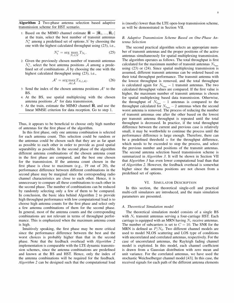
Algorithm 2 Two-phase antenna selection based adaptivetransmission scheme for HST scenario.
1: Based on the MIMO channel estimate H = [H1, ..., HC ]at the train, select the best number of transmit antennasN∗
t among a predefined set of options N by choosing theone with the highest calculated throughput using (23), i.e.,
N∗t = arg max
Nt∈NTNt . (25)
2: Given the previously chosen number of transmit antennasN∗
t , select the best antenna positions A among a prede-fined set of combinations A by choosing the one with thehighest calculated throughput using (23), i.e.,
A∗ = argmaxA∈A
TNt(A). (26)
3: Send the index of the chosen antenna positions A∗ to theBS.
4: At the BS, use spatial multiplexing with the chosenantenna positions A∗ for data transmission.
5: At the train, estimate the MIMO channel H, and use thelinear MMSE criterion for data reception. Go to step 1.
Thus, it appears to be beneficial to choose only high numberof antennas for the first phase of the algorithm.
In this first phase, only one antenna combination is selectedfor each antenna count. This selection could be random orthe antennas could be chosen such that they are as far apartas possible to each other in order to provide as good spatialseparability as possible. In the second phase of the algorithmdifferent antenna combinations of the chosen antenna countin the first phase are compared, and the best one chosenfor the transmission. If the antenna count chosen in thefirst phase is close to maximum (e.g., 19 out of 20), theperformance difference between different combinations in thesecond phase may be marginal since the corresponding radiochannel characteristics are close to each other. Hence, it isunnecessary to compare all these combinations to each other inthe second phase. The number of combinations can be reducedby randomly selecting only a few of them to be compared.In conclusion, the basic idea behind Algorithm 2 to providehigh throughput performance with low computational load is tochoose high antenna counts for the first phase and select onlya few antenna combinations of them for the second phase.In general, most of the antenna counts and the correspondingcombinations are not relevant in terms of throughput perfor-mance. This is emphasized when the maximum antenna countis high.
Intuitively speaking, the first phase may be more criticalsince the performance difference between the best and theworst choices is probably higher than that in the secondphase. Note that the feedback overhead with Algorithm 2implementation is comparable with the LTE dynamic transmis-sion schemes, since the antenna combinations are predefinedand known at the BS and HST. Hence, only the index ofthe antenna combinations will be required for the feedback.Algorithm 2 can be designed such that the computational load
is (mostly) lower than the LTE open-loop transmission scheme,as will be demonstrated in Section VII.
B. Adaptive Transmission Scheme Based on One-Phase An-tenna Selection
The second practical algorithm selects an appropriate num-ber of transmit antennas and the proper positions of the activeantennas simultaneously for spatial multiplexing transmission.The algorithm operates as follows. The total throughput is firstcalculated for the maximum number of transmit antennas Ntmax
using (23) or (24). Since spatial multiplexing transmission isassumed, different transmit antennas can be ordered based ontheir total throughput performance. The transmit antenna withthe lowest throughput is removed, and the total throughputis calculated again for Ntmax − 1 transmit antennas. The twocalculated throughput values are compared. If the first value ishigher, the maximum number of transmit antennas is chosenfor spatial multiplexing based data transmission. Otherwise,the throughput of Ntmax − 1 antennas is compared to thethroughput calculated for Ntmax − 2 antennas when the secondworst antenna is removed. The process of reducing the numberof transmit antennas one after the other based on the lowestper transmit antenna throughput is repeated until the totalthroughput is decreased. In practice, if the total throughputdifference between the current and previous case is relativelysmall, it may be worthwhile to continue the process until theperformance difference is large enough. Therefore, there canbe a predefined threshold α for the throughput difference,which needs to be exceeded to stop the process, and selectthe previous number and positions of the transmit antennas.The second antenna selection based transmission scheme issummarized in Algorithm 3. It will be shown in Section VIIthat Algorithm 3 has even lower computational load than thatof Algorithm 2. However, the feedback overhead is somewhathigher since the antenna positions are not chosen from apredefined set of options.
VI. SIMULATOR DESCRIPTION
In this section, the theoretical single-cell and practicalmulti-cell simulators are introduced, and the main simulationparameters are presented.
A. Theoretical Simulation modelThe theoretical simulation model consists of a single BS
with Nt transmit antennas serving a four-carriage HST. Eachcarriage is equipped with an MRN having Nr receive antennas.The number of subcarriers is set to C = 10. The SNR for theMRN is defined as P/N0. Two different channel models areused to model NLOS scattering and LOS type of conditionswith uncorrelated and correlated antennas, respectively. For thecase of uncorrelated antennas, the Rayleigh fading channelmodel is exploited. In this model, each channel coefficientis drawn from a Gaussian distribution with zero mean andunit variance. For the correlated antennas, we have used thestochastic Weichselberger channel model [43]. In this case, thereceived signals for each path of the different antenna elements

9
Algorithm 3 One-phase antenna selection based adaptivetransmission scheme for HST scenario.
1: Based on the MIMO channel estimate H = [H1, ..., HC ] atthe train, calculate the total throughput for the maximumnumber of transmit antennas Ntmax using (23). Set Nt =Ntmax .
2: Remove the antenna with the lowest throughput, andcalculate the total throughput for Nt − 1 antennas using(23). Compare the throughput values TNt and TNt−1.
3: ifTNt > TNt−1 (27)
4: Stop, and choose Nt transmit antennas and the corre-sponding antenna positions.
5: else6: Set Nt = Nt − 1, and go to step 2.7: end8: Send the information of the chosen transmit antennas to
the BS.9: At the BS, use spatial multiplexing with the chosen
transmit antennas for data transmission.10: At the train, estimate the MIMO channel H, and use the
linear MMSE criterion for data reception. Go to step 1.
are to be spatially correlated. Hence, spatial correlation matri-ces are generated to reflect the spatial correlation among theantenna elements. The spatial correlation coefficients for theBS and MRNs are generated according to
Rb =
1 ρb1,2 · · · ρb1,Nt
ρb2,1 1 · · · ρb2,Nt
......
. . ....
ρbNt,1ρbNt,2
· · · 1
, Rr =
1 ρr1,2 · · · ρr1,G
ρr2,1 1 · · · ρr2,G...
.... . .
...ρrG,1 ρrG,2 · · · 1
(28)
where G is defined as G = Nr and G = MNr for MRN non-cooperative mode and MRN cooperative mode respectively.The correlation coefficients are defined as
ρbi,j = Lijµ, ∀i = 1, ..., Nt; l = 1, ..., Nt i = j
ρrk,l = Lklµ, ∀k = 1, ..., G; l = 1, ..., G k = l(29)
where µ denotes a correlation factor generated randomly froma uniform distribution in the range (0, 1), while Lij and Lkl arenormalized path losses generated from the ”Rural Macro” pathloss model in [44]. The perpendicular distance between the BSand train, antenna spacing and mean angle of arrival (AoA) aretaken into account in the calculation of the path losses. Themean AoA is derived from a uniform distribution in the range(−π/2, π/2). The overall channel was modeled according tothe Weichselberger model Hc = UBS(Ω ⊙Hiid)U
TMRN [43],
which gives a better correlation structure than the Kroneckerchannel model [45]. UBS and UMRN are the orthonormaleigenvectors derived from the spatial correlation matricesfor the BS and MRN, respectively. Symbol ⊙ representsan element-wise multiplication and the coupling matrix Ω,whose structure reflects the spatial arrangement of scatteringobjects, is derived from the eigenvalues of Rb and Rr. In eachsimulation, the performance is averaged over 1000 independent
channel realizations. The main simulation parameters for thecase of correlated antennas are listed in Table I.
TABLE I: Simulation parameters for theoretical scenario (withcorrelated antennas).
Parameters ValuesCarrier frequency 2 GHz
Number of channel realization 1000
BS antenna spacing 0.5 wavelength
Length of each carriage 40 m
⊥ distance (BS → HST) 70 m
MRN antenna spacing Length of carriage/number of MRN antennas
Number of BS/MRN antennas 4, 8, 12, 16
correlation factor Uniform distribution (0, 1)
Angle of arrival Uniform distribution (−π/2, π/2)
B. Practical Simulation ModelThe practical HST simulation model is based on a realistic
wrap around multi-cell environment with a central layoutof 57 cells (19 tri-sector antenna sites). This central layoutis wrapped around with the copies of it to ensure uniforminterference levels across the 57 cells, as shown in Fig. 2.The simulation run consists of 1000 drops with 50 channelsamples per drop. 100 ground users are randomly distributedthroughout the central layout at the start of each drop. Therail is laid across the central layout with a radius of 5 kmsuch that the closest distance to any BS along the rail is 50m. The movement of the HST is modeled such that the HSTmoves incrementally along the rail at the start of each drop.The ground users and MRNs on the HST are paired with 57cells providing the strongest received signal strength, which iscalculated based on distance dependent pathloss and angularantenna gain. The pairings remain constant throughout eachdrop, therefore handover processes are not considered as such.MIMO-OFDM system operating in FDD mode is consideredwith a channel bandwidth of 10 MHz according to the LTEstandards [46].
At every transmission time interval (TTI), the resourcescheduler at the BS distributes available resources among theactive ground users and MRNs such that the overall throughputis maximized and the resources are fairly distributed. Theresources are shared based on a modified proportional fairscheduling algorithm. First, the scheduler differentiates groundusers from MRN and then splits the resources between groundusers and MRN backhaul links based on the number of activeground users and MRNs. A maximum of 50 percent of theresources are made available to the BS to train backhaul linksdue to the half duplex operation of the MRN. Schedulingrelies on channel information feedback, which may includeCQI, PMI, RI and the proposed antenna selection indexing.Following the LTE framework, the channel feedback informa-tion is obtained by the receiver/MRN and is made availableto the scheduler with a periodicity of 6 ms interval and 2 msdelay. The values of the feedback periodicity and delay dependon factors such as the granularity of the channel feedbackinformation subband reporting, the capability of user equip-ment, and higher layer message (e.g., radio resource control

10
(RRC) Connection Reconfiguration, RRC Connection Setup)[46]. The calculated channel feedback information is based onthe channel coefficients made available at the receiver/MRN.Random errors are introduced into the channel coefficientsbefore calculating the channel feedback information, to modelchannel estimation errors as no specific channel estimator wasimplemented. The channel coefficients are generated based onthe WINNER II channel model [33]. It is a geometry basedmodel that enables the separation of propagation parametersand antennas. Some of the parameters needed for the channelgeneration include the propagation scenario, the speed anddirection of the UE, number, height, and location of the BSand MS/MRN, antenna field patterns, system centre frequency,etc. Based on the delayed channel feedback information, amodulation and coding scheme (MCS) is set for each terminalat the BS for the next transmission.
A link to system (L2S) level interface is used to map the linklevel SINR values to the system level throughput performance.More precisely, the obtained SINRs are mapped to mutualinformation values using mutual information effective SINRmetric (MIESM) link layer abstraction [47]. The MCS valuesdetermine the frame error probability (FEP) at the link tosystem level interface and define the transport block size, i.e.,the number of bits transmitted. The success of transmissionsis identified by hybrid automatic repeat request (HARQ) ac-knowledgements, which are determined in the system level in-terface and fed back to the BS after a delay. The number of bitstransmitted for successful transmissions and retransmissionsare used in the throughput calculations. The described systemlevel simulator is LTE compliant. The simulation parametersare set according to the guidelines established by the inter-national telecommunications union radiocommunication sector(ITU-R) for international mobile telecommunications advanced(IMT-A) radio interface evaluation [48]. The main simulationparameters are listed in Table II.
TABLE II: Simulation parameters for practical scenario.
Parameters ValuesCarrier frequency 2 GHz
System bandwidth 10 MHz
Transmit power 46 dBm
Number of ground users 100
Number of MRNs 8 (1 in each carriage)
Propagation scenario suburban macro/rural moving networks
Inter-site distance (ISD) 1.3 km
Traffic Model Full buffer
MRN duplex mode half duplex FDD
Length of each carriage 30 m
Transmission scheme spatial multiplexing
HARQ chase combining
HARQ processes 6
Receiver type MMSE
L2S interface metric MIESM
Train speed 300 km/h
VII. SIMULATION RESULTS
In this section, the performance of different MIMO-OFDMtransmission schemes is evaluated via numerical examples in
5 10 15 20 250
10
20
30
40
50
60
70
80
90
100
110
120
SNR [dB]
Rate
[b/s
/Hz]
COP: Nt= 4; N
rTot= 4
COP: Nt= 8; N
rTot= 8
COP: Nt= 12; N
rTot= 12
COP: Nt= 16; N
rTot= 16
NonCOP: Nt= 4; N
rTot= 4
NonCOP: Nt= 8; N
rTot= 8
NonCOP: Nt= 12; N
rTot= 12
NonCOP: Nt= 16; N
rTot= 16
(a) i.i.d channel
5 10 15 20 250
10
20
30
40
50
60
70
80
90
100
SNR [dB]
Rate
[b/s
/Hz]
COP: Nt= 4; N
rTot= 4
COP: Nt= 8; N
rTot= 8
COP: Nt= 12; N
rTot= 12
COP: Nt= 16; N
rTot= 16
NonCOP: Nt= 4; N
rTot= 4
NonCOP: Nt= 8; N
rTot= 8
NonCOP: Nt= 12; N
rTot= 12
NonCOP: Nt= 16; N
rTot= 16
(b) Correlated channel
Fig. 3: Achieved sum rate for cooperative and non-cooperativeMRN system.
theoretical and practical simulation models. First, we com-pare the performance of the cooperative and non-cooperativeMRN systems with the increasing number of transmit andreceive antennas in a simple single-cell scenario. Then, theperformance of the LTE-based precoding schemes and theproposed simplified antenna selection algorithms are comparedin a practical HST scenario. Finally, we study how muchthe throughput performance can be improved by increasingthe number of transmit and receive antennas in the practicalscenario.
In Fig. 3, the achieved sum rate is plotted against SNR forthe cooperative (COP) and non-cooperative (NonCOP) MRNsystems with different numbers of transmit and receive anten-nas in uncorrelated and correlated channels. The total numberof receive antennas at the train is denoted by NrTot = MNr.The simulation results show that the cooperation of MRNs ishighly beneficial compared to non-cooperative scheme at allSINR values. The performance gain increases with the increas-

11
ing number of transmit and receive antennas. The gains areeven higher in the correlated channel conditions, even thoughthe absolute performance is somewhat decreased comparedto the uncorrelated channels due to the reduction of spatialdegrees of freedom. The superior performance of cooperativescheme is due to a fact that the overall MIMO channel from theBS to the entire train can be divided into parallel interference-free sub-channels with proper transmit and receive processingthrough the SVD. In the non-cooperative scheme with theindependent data reception of each MRN, inter-MRN andinter-stream interferences limit the throughput performance. Inother words, the spatial separability of the transmitted signalsat the receiver side is more efficient for the cooperative schemesince it can exploit all the receive antennas and the physicallength of the train. In conclusion, the theoretical results implythat the MRNs in the train should cooperate if possible andthe antenna arrays at the BS and the train should be as large aspractically possible. Hence for the rest of the paper, we onlyconsider the cooperative scheme.
Before examining the performance analysis for differenttransmission schemes, we show the impact of different trainspeeds on the throughput of the cooperative scheme. Fig. 4
0 10 20 30 40 50 60 70 80 90 1000
0.1
0.2
0.3
0.4
0.5
0.6
0.7
0.8
0.9
1
Throughput [Mb/s]
C D
F
HST Speed: 300 km/h
HST Speed: 75 km/h
HST Speed: 3 km/h
Fig. 4: CDF plot of throughput for different HST speed.
shows the cumulative distribution function (CDF) of thethroughput for three different train speeds with antenna con-figuration of Nt = 4 and Nr = 2 for each of the MRN. Theresults show the trend that throughput decreases as the speedincreases. The difference in the throughput is mainly a result ofthe impact of the delayed feedback of the channel informationw.r.t. the channel and speed of the HST.1 Due to high speed,feedback information gets outdated fast.
In all the following simulations, the total transmit power ofa BS is assumed fixed (i.e., 46 dBm) and this power is equallydivided among the transmit antennas, regardless of the numberof antennas used. Fig. 5 illustrates the CDF of the throughput
1The effect of Doppler shift and handover at different vehicular speeds wereexamined in [49].
for different transmission schemes at 300 km/h train speed.The following transmission schemes are considered• Spatial multiplexing: fixed rank (S-MUX)• LTE closed-loop: fixed rank (LTE CL)• LTE open-loop: fixed rank (LTE OL)• LTE closed-loop: dynamic rank (LTE CL-dynamic rank)• LTE open-loop: dynamic rank (LTE OL-dynamic rank)• Spatial multiplexing: exhaustive search over all possible
antenna combinations (S-MUX exhaustive search).
20 40 60 80 100 1200
0.1
0.2
0.3
0.4
0.5
0.6
0.7
0.8
0.9
1
Throughput [Mbps]
C D
F
S−MUX
LTE CL
LTE OL
LTE CL−dynamic rank
LTE OL−dynamic rank
S−MUX exhaustive search
Fig. 5: CDF plot of throughput for fixed and adaptive trans-mission schemes with Nt = 4 and Nr = 4.The results show that all the fixed rank transmission schemeshave nearly comparable performance, regardless of the precod-ing. Thus, precoding-based schemes hardly provide any gainover the S-MUX. However, the dynamic rank transmissionsprovide significant performance gains as compared with thefixed rank schemes. It can be seen that the LTE OL-dynamicrank scheme slightly outperforms the CL one. The superiorthroughput performance can be achieved by using the S-MUX with exhaustive search. The results imply that usingprecoding may not provide any gains in a practical HSTscenario. However, significant gains seem to be available byusing adaptive transmission schemes.
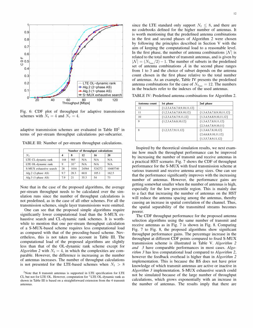
In Fig. 6, the CDF throughput performance of the proposedantenna selection (AS) algorithms is compared with the LTEOL-dynamic rank and the S-MUX exhaustive search transmis-sion schemes. The proposed algorithms are represented as• Alg.2 (2-phase AS)• Alg.3 (1-phase AS).
As can be seen, the proposed algorithms achieve almostcomparable performance to that of the S-MUX with exhaustivesearch, yet with significantly reduced computational load. Theresults also show that the proposed algorithms provide someperformance gains when compared with the LTE OL-dynamicrank transmission scheme.
The computational loads involved for performing different
12
20 40 60 80 100 1200
0.1
0.2
0.3
0.4
0.5
0.6
0.7
0.8
0.9
1
Throughput [Mbps]
C D
F
LTE OL−dynamic rank
Alg.2 (2−phase AS)
Alg.3 (1−phase AS)
S−MUX exhaustive search
Fig. 6: CDF plot of throughput for adaptive transmissionschemes with Nt = 4 and Nr = 4.
adaptive transmission schemes are evaluated in Table III2 interms of per-stream throughput calculations per-subcarrier.
TABLE III: Number of per-stream throughput calculations.
Number of throughput calculationsNt 4 8 12 16 20LTE CL-dynamic rank 144 905 N/A N/A N/A
LTE OL-dynamic rank 9 35∗ N/A N/A N/A
S-MUX exhaustive search 28 1016 24564 524272 10485740
Alg.2 (2-phase AS) 9.7 28.3 60.8 105.1 162.5
Alg.3 (1-phase AS) 7.9 21 35.3 54 73
Note that in the case of the proposed algorithms, the averageper-stream throughput needs to be calculated over the sim-ulation runs since the number of throughput calculations isnot predefined, as in the case of all other schemes. For all thetransmission schemes, single layer transmissions were omitted.
One can see that the proposed simple algorithms requiresignificantly lower computational load than the S-MUX ex-haustive search and CL-dynamic rank schemes. It is worth-while to mention that one per-stream throughput calculationof a S-MUX-based scheme requires less computational loadas compared with that of the precoding-based scheme. Nev-ertheless, this is not taken into account in Table III. Thecomputational load of the proposed algorithms are slightlyless than that of the OL-dynamic rank scheme except forAlgorithm 2 with Nt = 4, in which the complexities are com-parable. However, the difference is increasing as the numberof antennas increases. The number of throughput calculationsis not presented for the LTE-based schemes when Nt > 8
2Note that 8 transmit antennas is supported in LTE specification for LTECL but not for LTE OL. However, computation for ∗LTE OL-dynamic rank asshown in Table III is based on a straightforward extension from the 4 transmitantennas.
since the LTE standard only support Nt ≤ 8, and there areno codebooks defined for the higher number of antennas. Itis worth mentioning that the predefined antenna combinationsin the first and second phases of Algorithm 2 were chosenby following the principles described in Section V with theaim of keeping the computational load to a reasonable level.In the first phase, the number of antenna combinations |N | isrelated to the total number of transmit antennas, and is given by|N | = (Ntmax/2)− 1. The number of subsets in the predefinedset of antenna combinations A in the second phase rangesfrom 1 to 3 and the choice of subset depends on the antennacount chosen in the first phase relative to the total numberof antennas. As an example, Table IV presents the predefinedantenna combinations for the case of Ntmax = 12. The numbersin the brackets refer to the indexes of the used antennas.
TABLE IV: Predefined antenna combinations for Algorithm 2.
Antenna count 1st phase 2nd phase12 1,2,3,4,5,6,7,8,9,10,11,12 -
11 1,2,3,4,5,6,7,8,9,10,12 1,3,4,5,6,7,8,9,10,11,1210 1,2,3,4,5,6,7,9,11,12 1,3,4,5,6,8,9,10,11,129 1,2,3,4,5,6,8,10,12 1,3,4,5,7,8,9,11,12
2,3,4,6,7,8,9,10,118 1,2,3,5,7,9,11,12 1,3,4,6,7,8,10,12
2,4,6,8,9,10,11,121,3,5,7,8,9,11,12
Inspired by the theoretical simulation results, we next exam-ine how much the throughput performance can be improvedby increasing the number of transmit and receive antennas ina practical HST scenario. Fig. 7 shows the CDF of throughputperformance for the S-MUX with fixed transmission scheme atvarious transmit and receive antenna array sizes. One can seethat the performance significantly improves with the increasingnumber of antennas. However, the performance gains aregetting somewhat smaller when the number of antennas is high,especially for the low percentile region. This is mainly dueto a fact that increasing the number of antennas on the HSTwill reduce the antenna spacing among the antennas, therebycausing an increase in spatial correlation of the channel. Thus,the spatial separability of the transmitted streams becomespoorer.
The CDF throughput performance for the proposed antennaselection algorithms using the same number of transmit andreceive antennas as in Fig. 7 is shown in Fig. 8. ComparingFig. 7 to Fig. 8, the proposed algorithms show significantthroughput performance gains. The percentage increase in thethroughput at different CDF points compared to fixed S-MUXtransmission scheme is illustrated in Table V. Algorithm 2and 3 have comparable performances in most cases. Algo-rithm 3 has less computational load compared to Algorithm 2,however the feedback overhead is higher than in Algorithm 2implementation. This is because the BS does not have priorknowledge of which transmit antennas are active or inactive inAlgorithm 3 implementation. S-MUX exhaustive search couldnot be simulated because of the large number of throughputcalculations, which grows exponentially with an increase inthe number of antennas. The results imply that there are

13
50 100 150 200 250 3000
0.1
0.2
0.3
0.4
0.5
0.6
0.7
0.8
0.9
1
Throughput [Mbps]
C D
F
S−MUX: Nt= 8; N
r= 8
S−MUX: Nt= 12; N
r= 12
S−MUX: Nt= 16; N
r= 16
S−MUX: Nt= 20; N
r= 20
Fig. 7: CDF plot of throughput for fixed S-MUX transmissionwith increasing number of antennas.
50 100 150 200 250 300 350 4000
0.1
0.2
0.3
0.4
0.5
0.6
0.7
0.8
0.9
1
Throughput [Mbps]
C D
F
Nt= 8: Alg.2 (2−phase AS)
Nt= 8: Alg.3 (1−phase AS)
Nt= 12: Alg.2 (2−phase AS)
Nt= 12: Alg.3 (1−phase AS)
Nt= 16: Alg.2 (2−phase AS)
Nt= 16: Alg.3 (1−phase AS)
Nt= 20: Alg.2 (2−phase AS)
Nt= 20: Alg.3 (1−phase AS)
Fig. 8: CDF plot of throughput for the proposed adaptivetransmission schemes with increasing number of antennas.
significant throughput gains available by increasing the numberof antennas and using the proposed low complexity algorithms.
VIII. DISCUSSION
The simulation results imply that the key point for im-proving the throughput performance in a HST scenario is touse sufficiently large antenna arrays at the BS and train. Theresults also demonstrate that precoding is somewhat irrelevant,but transmission rank adaption via exhaustive search type ofprocess is highly beneficial. However, rank adaptation requiresa lot of computation, especially when using large antennaarrays. The key insight in reducing the computational loadof the system is to simplify the exhaustive search process bycomparing only the most relevant combinations, i.e., focusingon choosing the right number of transmit antennas rather
TABLE V: Performance gains of the proposed adaptive algo-rithms over fixed S-MUX scheme.
% increase in throughput performance compared to S-MUXCDF Alg.2 (2-phase AS) Alg.3 (1-phase AS)Nt 4 8 12 16 20 4 8 12 16 20
0.2 32% 45% 22% 42% 48% 35% 44% 30% 39% 42%
0.5 6.3% 34% 19% 27% 22% 6.3% 34% 26% 19% 22%
0.7 17% 20% 22% 22% 18% 17% 20% 25% 12% 17%
0.9 30% 21% 9% 19% 11% 30% 17% 9% 18% 11%
than going through all the possible combinations. It wasshown that the proposed low complexity algorithms includingspatial multiplexing with simplified antenna selection provideperformance almost comparable with that of the exhaustivesearch scheme, but with notably reduced computational load.In conclusion, large antenna arrays at the transmitting andreceiving sides, with simple spatial multiplexing and antennaselection transmission scheme seem an appropriate solution tosignificantly improve the backhaul link throughput in a practi-cal HST communication scenario. These simplified algorithmsalso fit in well to real-time demanding scenarios such as thehigh speed moving receivers, where the time taken to selectan appropriate transmission scheme is significantly reduced asa result of the reduced computational load.
IX. CONCLUSION
This paper considered a MIMO-OFDM HST communica-tion system where the focus was on the backhaul link optimiza-tion with the aim of throughput maximization. This problemwas approached from both theoretical and practical aspects.The theoretical results showed that cooperation between theMRNs and increasing the number of antennas is highly bene-ficial. In a practical HST scenario, it was shown that adaptiverank transmission schemes provide significant throughput gainsover fixed rank schemes. However, adaptive schemes mayrequire extensive amount of computation, especially whenthe number of antennas is high. To significantly reduce thecomputational load, we proposed two low complexity trans-mission schemes with simplified antenna selection and spatialmultiplexing. The practical simulation results demonstratedthat the proposed simple algorithms provide almost similarperformance as compared with the spatial multiplexing withexhaustive search and improved throughput performance ascompared with the LTE-based dynamic rank schemes. Further-more, computational load was significantly reduced. It was alsoshown that the throughput is further improved by combiningthe proposed low complexity algorithms with large antennaarrays.
REFERENCES
[1] X. Zhu, S. Chen, H. Hu, X. Su, and Y. Shi, “TDD-based mobile com-munication solutions for high-speed railway scenarios,” IEEE WirelessCommun. Mag., vol. 20, no. 6, pp. 22–29, Dec. 2013.
[2] H. Bolcskei, “MIMO-OFDM wireless systems: basics, perspectives, andchallenges,” IEEE Trans. Wireless Commun., vol. 13, no. 4, pp. 31–37,Aug. 2006.
14
[3] R. He, Z. Zhong, B. Ai, G. Wang, J. Ding, and A. F. Molisch,“Measurements and analysis of propagation channels in high-speedrailway viaducts,” IEEE Trans. Wireless Commun., vol. 12, no. 2, pp.794–805, Feb. 2013.
[4] R. He, Z. Zhong, and B. Ai, “Path loss measurements and analysis forhigh-speed railway viaduct scene,” in Proc. Int. Wireless Commun. andMobile Computing Conf., Jun. 2010, pp. 266–270.
[5] R. He, Z. Zhong, B. Ai, and J. Ding, “Measurements and analysisof short-term fading behavior for high-speed rail viaduct scenario,” inProc. IEEE Int. Conf. Commun., Jun. 2012, pp. 4563–4567.
[6] R. He, Z. Zhong, B. Ai, J. Ding, Y. Yang, and A. F. Molisch, “Short-termfading behavior in high-speed railway cutting scenario: measurements,analysis, and statistical models,” IEEE Trans. Antennas Propag., vol. 61,no. 4, pp. 2209–2222, Apr. 2013.
[7] F. Luan, Y. Zhang, L. Xiao, C. Zhou, and S. Zhou, “Fading characteris-tics of wireless channel on high-speed railway in hilly terrain scenario,”Int. J. Antennas and Propag., vol. 2013, Jan. 2013.
[8] P. Aikio, R. Gruber, and P. Vainikainen, “Wideband radio channelmeasurements for train tunnels,” in Proc. IEEE Veh. Technol. Conf.,vol. 1, May 1998, pp. 460–464.
[9] T. Zhou, C. Tao, S. Salous, L. Liu, and Z. Tan, “Channel soundingfor high-speed railway communication systems,” IEEE Commun. Mag.,vol. 53, no. 10, pp. 70–77, Oct. 2015.
[10] B. Ai, X. Cheng, T. Kurner, Z.-D. Zhong, K. Guan, R.-S. He, L. Xiong,D. Matolak, D. Michelson, and C. Briso-Rodriguez, “Challenges towardwireless communications for high-speed railway,” IEEE Trans. Intell.Transp. Syst., vol. 15, no. 5, pp. 2143–2158, 2014.
[11] J. Wang, H. Zhu, and N. J. Gomes, “Distributed antenna systemsfor mobile communications in high speed trains,” IEEE J. Sel. AreasCommun., vol. 30, no. 4, pp. 675–683, May 2012.
[12] V. Van Phan, K. Horneman, L. Yu, and J. Vihriala, “Providing enhancedcellular coverage in public transportation with smart relay systems,” inProc. IEEE Veh. Networking Conf., Dec. 2010, pp. 301–308.
[13] D. T. Fokum and V. S. Frost, “A survey on methods for broadbandinternet access on trains,” IEEE Commun. Surveys Tuts., vol. 12, no. 2,pp. 171–185, Second Quarter 2010.
[14] G. Tingting and S. Bin, “A high-speed railway mobile communicationsystem based on LTE,” in Proc. IEEE Int. Conf. Electron. and Inform.Eng., vol. 1, Aug. 2010, pp. 414–417.
[15] B. Ai, K. Guan, M. Rupp, T. Kurner, X. Cheng, X.-F. Yin, Q. Wang, G.-Y. Ma, Y. Li, L. Xiong et al., “Future railway services-oriented mobilecommunications network,” IEEE Commun. Mag., vol. 53, no. 10, pp.78–85, Oct. 2015.
[16] E. Tanghe, W. Joseph, L. Verloock, and L. Martens, “Evaluation ofvehicle penetration loss at wireless communication frequencies,” IEEETrans. Veh. Technol., vol. 57, no. 4, pp. 2036–2041, Jul. 2008.
[17] S. Scott, J. Leinonen, P. Pirinen, J. Vihriala, V. Van Phan, and M. Latva-aho, “A cooperative moving relay node system deployment in a highspeed train,” in Proc. IEEE Veh. Technol. Conf., Jun. 2013, pp. 1–5.
[18] Y. Sui, J. Vihriala, A. Papadogiannis, M. Sternad, W. Yang, andT. Svensson, “Moving cells: a promising solution to boost performancefor vehicular users,” IEEE Commun. Mag., vol. 51, no. 6, pp. 62–68,Jun. 2013.
[19] L. Tian, J. Li, Y. Huang, J. Shi, and J. Zhou, “Seamless dual-linkhandover scheme in broadband wireless communication systems forhigh-speed rail,” IEEE J. Sel. Areas Commun., vol. 30, no. 4, pp. 708–718, May 2012.
[20] W. Luo, R. Zhang, and X. Fang, “A CoMP soft handover scheme forLTE systems in high speed railway,” EURASIP J. Wireless Commun.and Networking, vol. 2012, no. 1, pp. 1–9, Jun. 2012.
[21] W. Luo, X. Fang, M. Cheng, and Y. Zhao, “Efficient multiple-groupmultiple-antenna (MGMA) scheme for high-speed railway viaducts,”IEEE Trans. Veh. Technol., vol. 62, no. 6, pp. 2558–2569, Jul. 2013.
[22] X. Cheng and X. Fang, “Principal component analysis based multiplex-
ing solution for MIMO systems in high-speed railway,” in Proc. HighMobility Wireless Commun. (HMWC), Nov. 2014, pp. 48–52.
[23] J.-Y. Zhang, Z.-H. Tan, and H.-B. Wang, “Optimum capacity of MIMOsystems for high-speed railway with spare antenna array,” in Proc. IEEEVeh. Technol. Conf., May 2011, pp. 1–4.
[24] N. Sun and J. Wu, “Maximizing spectral efficiency for high mobilitysystems with imperfect channel state information,” IEEE Trans. WirelessCommun., vol. 13, no. 3, pp. 1462–1470, Mar. 2014.
[25] S. Valentin and T. Wild, “Studying the sum capacity of mobile multiuserdiversity systems with feedback errors and delay,” in Proc. IEEE Veh.Technol. Conf., Sep. 2010, pp. 1–5.
[26] A. Yilmaz and O. Kucur, “Performances of transmit antenna selection,receive antenna selection, and maximal-ratio-combining-based hybridtechniques in the presence of feedback errors,” IEEE Trans. Veh.Technol., vol. 63, no. 4, pp. 1976–1982, May 2014.
[27] L. Li, S. A. Vorobyov, and A. B. Gershman, “Transmit antenna selectionbased strategies in MISO communication systems with low-rate channelstate feedback,” IEEE Trans. Wireless Commun., vol. 8, no. 4, pp. 1660–1666, Apr. 2009.
[28] C. Mun, “Transmit-antenna selection for spatial multiplexing withordered successive interference cancellation,” IEEE Trans. Commun.,vol. 54, no. 3, pp. 423–429, Mar. 2006.
[29] D. A. Gore, R. W. Heath Jr, and A. J. Paulraj, “Transmit selection inspatial multiplexing systems,” IEEE Commun. Lett., vol. 6, no. 11, pp.491–493, Nov. 2002.
[30] R. W. Heath Jr, S. Sandhu, and A. Paulraj, “Antenna selection for spatialmultiplexing systems with linear receivers,” IEEE Commun. Lett., vol. 5,no. 4, pp. 142–144, Apr. 2001.
[31] R. Klotsche, K. Wunstel, and T.-R. Banniza, “Doppler compensationcontrol for radio transmission,” Jan. 26 2010, US Patent 7,653,347.
[32] J. Li and Y. Zhao, “Radio environment map-based cognitive Dopplerspread compensation algorithms for high-speed rail broadband mobilecommunications,” EURASIP Journal Wireless Commun. and Network-ing, vol. 2012, no. 1, pp. 1–18, Aug. 2012.
[33] “WINNER II channel models, D1.1.2 V1.2 http://http://www.ist-winner.org/deliverables.html.”
[34] J. Kaleva, A. Tolli, and M. Juntti, “Weighted sum rate maximizationfor interfering broadcast channel via successive convex approximation,”in Proc. IEEE Global Commun. Conf., Dec. 2012, pp. 3838–3843.
[35] Q. Shi, M. Razaviyayn, Z.-Q. Luo, and C. He, “An iteratively weightedMMSE approach to distributed sum-utility maximization for a MIMOinterfering broadcast channel,” IEEE Trans. Signal Process., vol. 59,no. 9, pp. 4331–4340, Sep. 2011.
[36] D. Tse and P. Viswanath, Fundamentals of Wireless Communication.Cambridge University Press, 2005.
[37] D. J. Love, R. W. Heath, W. Santipach, and M. L. Honig, “What is thevalue of limited feedback for MIMO channels?” IEEE Commun. Mag.,vol. 42, no. 10, pp. 54–59, Oct. 2004.
[38] B. M. Hochwald, T. L. Marzetta, T. J. Richardson, W. Sweldens, andR. Urbanke, “Systematic design of unitary space-time constellations,”IEEE Trans. Inf. Theory, vol. 46, no. 6, pp. 1962–1973, Sep. 2000.
[39] A. G. Dabak, C. Lin, E. N. Onggosanusi, and B. Varadarajan, “Code-book and pre-coder selection for closed-loop MIMO,” May 24 2011,US Patent 7,949,064.
[40] J. Lee, J.-K. Han, and J. Zhang, “MIMO technologies in 3GPP LTEand LTE-Advanced,” EURASIP J. Wireless Commun. and Networking,vol. 2009, Jul. 2009.
[41] J. Roessler, “LTE-Advanced (3GPP Rel. 12) technology introductionwhite paper,” Feb. 2015.
[42] A. O. Laiyemo, P. Pirinen, and M. Latva-aho, “Alternative to dynamicrank transmission for LTE mobile relay node system,” in Proc. Euro-pean Wireless Conf., May 2014, pp. 1–6.
[43] W. Weichselberger, M. Herdin, H. Ozcelik, and E. Bonek, “A stochastic
15
MIMO channel model with joint correlation of both link ends,” IEEETrans. Wireless Commun., vol. 5, no. 1, pp. 90–100, Jan. 2006.
[44] “3rd Generation Partnership Project; Technical Specification GroupRadio Access Network; Evolved Universal Terrestrial Radio Access(E-UTRA); Further advancements for E-UTRA physical layer aspects,”3GPP, Rep. TR 36.814 V9.0.0,” Technical Specification, 2010.
[45] J. P. Kermoal, L. Schumacher, K. I. Pedersen, P. E. Mogensen, andF. Frederiksen, “A stochastic MIMO radio channel model with exper-imental validation,” IEEE J. Sel. Areas Commun., vol. 20, no. 6, pp.1211–1226, Aug. 2002.
[46] “3rd Generation Partnership Project; Technical Specification GroupRadio Access Network; Evolved Universal Terrestrial Radio Access (E-UTRA); Physical layer procedures,” 3GPP, Rep. TR 36.213 V10.6.0,”Technical Specification, 2012.
[47] X. He, K. Niu, Z. He, and J. Lin, “Link layer abstraction in MIMO-OFDM system,” in Proc. IEEE Int. Workshop on Cross Layer Design(IWCLD), Sep. 2007, pp. 41–44.
[48] M. Series, “Guidelines for evaluation of radio interface technologies forIMT-Advanced,” ITU, Tech. Rep., 2009.
[49] S. Tenorio, P. Spence, B. Garriga, J. Lopez, A. Garcıa, and M. Arranz,“3G HSPA for broadband communications with high speed vehicles,”in Proc. IEEE Veh. Technol. Conf., Apr. 2010, pp. 1–5.


![Throughput Maximization for Two-way Relay Channels with ... · arXiv:1504.07615v2 [cs.IT] 29 Apr 2015 1 Throughput Maximization for Two-way Relay Channels with Energy Harvesting Nodes:](https://img.dokumen.tips/doc/110x75/5ad10ce27f8b9ae2138e68d1/throughput-maximization-for-two-way-relay-channels-with-150407615v2-csit.jpg)


![Throughput Maximization in Wireless Powered ...arXiv:1304.7886v4 [cs.IT] 21 Jul 2014 Throughput Maximization in Wireless Powered Communication Networks Hyungsik Ju and Rui Zhang Abstract](https://img.dokumen.tips/doc/110x75/5e9602c0573273188b47b1d3/throughput-maximization-in-wireless-powered-arxiv13047886v4-csit-21-jul.jpg)


![New Throughput Maximization with an Average Age of Information … · 2019. 11. 19. · arXiv:1911.07499v1 [cs.IT] 18 Nov 2019 1 Throughput Maximization with an Average Age of Information](https://img.dokumen.tips/doc/110x75/604576c808b5d145af3f17b2/new-throughput-maximization-with-an-average-age-of-information-2019-11-19-arxiv191107499v1.jpg)