Embed Size (px)
Citation preview

ISSN: 2277-3754
ISO 9001:2008 Certified International Journal of Engineering and Innovative Technology (IJEIT)
Volume 6, Issue 3, September 2016
8
Abstract—This paper examines the probability of the bit
error rate (BER) and the spectral efficiency of the Orthogonal
Frequency Division Multiplexing (OFDM) system and introduces
the performance enhancement of using adaptive modulation in
the system. Best modulation scheme according to higher data
rates is investigated on the basis of channel quality indicators
(SNR, Doppler shift generated by receiver speed, and BER) for
different modulation types (QPSK, and M-QAM). Rayleigh
fading channel corrupted by AWGN is considered in the
simulation. The work also introduces an idea when channel
prediction is most valuable to adaptive modulation and when it is
not. The tables at the end of the paper show the conditions by
which the modulation type can changed. Matlab program has
been used to implement the whole system.
Index Terms—Bit Error Rate (BER), Signal to Noise Ratio
(SNR), Orthogonal Frequency Division Multiplexing (OFDM)
Adaptive Modulation, Cyclic-prefix (CP), Digital Modulation
Schemes, channel quality indicator (CQI) ,Rayleigh Fading
Channel, Doppler Effect and Additive White Gaussian Noise
(AWGN).
I. INTRODUCTION
During the past few years, there has been a huge
development in wireless technology. This development has
opened new applications of wireless communication without
location or movement constrains. These days, the maximum
data rates for 4G network is 1GB/s for indoor and 100MB/s
for outdoor environments [1].
These high data rates for indoor and outdoor
environments cannot be achieved by using single carrier
systems, because at high data rates the problem of inter-
symbol interference will arise and one symbol interferes to
another symbol periods. The data will be highly distorted,
therefore the need for multicarrier transmission systems
arises [2]. Multicarrier transmissions can be achieved by
dividing the available bandwidth into a number of narrow
bands called sub-bands. Each sub-band is modulated by a
sub-carrier and transmitted simultaneously with other sub-
carriers [3].
In recent years orthogonal frequency division
multiplexing (OFDM) has proven that it is one of the most
successful techniques. In context of wired environments,
OFDM techniques are also known as Discrete Multi-Tone
(DMT) transmissions and are employed in American
National Standard Institute’s (ANSI’s) Asymmetric Digital
Subscriber Line (ADSL) and Very high Digital Subscriber
Line (VDSL) standards as well as in the European
Telecommunication Standard Institute’s (ETSI’s). In
wireless scenario, OFDM has been used by many European
standards such as Digital Audio Broadcasting (DAB) Digital
Video Broadcasting for Terrestrial Television (DVB-T)
Digital Video Broadcasting for Handheld Terminals (DVB-
H), Wireless Location Area Networks (WLANs) and
Broadband Radio Access Networks (BRANs) [4] [5].
Arthur H. Ballard in 1966 [9] claimed a new technique for
multiplex communication, in which orthogonal pulse
waveforms were transmitted as simultaneous subcarriers.
Information signals were carried in the form of independent
amplitude modulations of each subcarrier, and were
extracted by means of waveform correlation. He named the
claimed new technique as ORTHOMUX (orthogonal
multiplexing), which offers the advantages of
1) High spectrum efficiency.
2) Maximum rejection of crosstalk and noise.
3) Information response down to zero frequency.
4) Mixed information rates.
5) Simple, compact equipment.
6) Modular flexibility.
Before 1971 the use of OFDM technique was limited on
the military applications because it required a bank of
sinusoidal subcarrier generators and demodulators. After
1971 Weinstein and Ebert [11] suggested that modulation
and demodulation processes of the OFDM system can be
implemented by using Inverse Discrete Fourier Transform
(IFFT) at the transmitter and Discrete Fourier Transform at
the receiver, which significantly reduces the complexity of
the OFDM system [4] [6].
Adaptive modulation is another important technique used
to increase the data rate, to get maximum data throughput
with acceptance Bit Error Rate (BER) [7]. The adaptive
modulation is done by estimated the channel SNR and the
Doppler frequency shift [8].
The need for communication with high data rate and
accepted bit error rate (BER) led to look for and investigate
new techniques of digital communication, and to use the
available bandwidth in efficient ways. Dinesh B. Bhoyar
et.al. in 1997 [1] tried to increase the spectrum efficiency
by using a good channel estimator with high order
modulation schemes.
J.Faezah, and K.Sabira in 2009 [10] considered only
adaptive modulation and investigated the OFDM system
performance of uncoded adaptive modulation using
quadrature amplitude modulation (QAM) and phase shift
keying (PSK). To further enhance the system, they tried to
employ convolutional coding to OFDM system. The
Data Throughput Maximization for Moving
Receiver Using Adaptive Modulation with
OFDM System Mohammed B. Shukur, Younis M. Abbosh

ISSN: 2277-3754
ISO 9001:2008 Certified International Journal of Engineering and Innovative Technology (IJEIT)
Volume 6, Issue 3, September 2016
9
obtained results show that a significant improvements in
terms of bit error rate (BER) and throughput can be
achieved demonstrating the superiority of the adaptive
modulation schemes compared to fixed transmission
schemes.
Sami H.O. Salih and Mamoun M.A. Suliman in 2011 [11]
Proposed high order modulation schemes which are used
with good conditions of the channel. The lower order
modulation schemes (BPSK, QPSK) are used with bad
conditions of the channel.
In 2012 Salima El Makhtari et.al [12] investigated the
performance evaluation of OFDM LTE downlink physical
layer according to the latest 3GPP specifications. The
investigation had been done by using AGWN channel and
for static receiver and transmitter.
Mustafa Dh. Hassib in 2014 [13] proposed a method to
estimate the link performance for space time block code
(STBC) systems with maximum likelihood detector (MLD).
This can be achieved by using a dispersion of receiving
symbols(DOS) in the constellation mapping to represent the
current channel state information (CSI) in subsequent frame
followed by the selection of an appropriate modulation
coding scheme for the next frame.
II. OFDM WIRELESS COMMUNICATION SYSTEM
The OFDM technique is the basic for many modern
communication systems such as the 3GPP Long Term
Evolution as a downlink transmission scheme, WiMax and
the Digital Video Broadcasting (DVB). The OFDM
transmission can be characterized as a multicarrier
transmission.
The basic characteristics of OFDM transmission are:[16]
1. Number of narrow subcarriers are simultaneously
transmitted to occupy the available bandwidth in
efficient way and some times the number of
subcarriers may be huge and can reach to thousand
subcarriers.
2. Usually the subcarrier spacing is ,
where is the per-subcarrier modulation symbol
time which is illustrated in Figure1. The subcarrier
spacing therefore equals to the per-subcarrier
modulation rate .
Fig 1 OFDM subcarrier spacing [16].
The term Orthogonal Frequency Division Multiplex is due
to the fact that two modulated OFDM subcarriers and
are mutually orthogonal over the time
interval ”, i.e. [16]
III. OFDM IMPLEMENTATION USING IFFT/FFT
PROCESSING
Although an OFDM modulation and demodulation can be
achieved by using a bank of parallel modulators and
correlators, respectively, but in actual implementation it is
difficult to get large numbers of modulators and correlators
that can work synchronously. In addition, the subcarrier
spacing which is equal to the per-subcarrier symbol
rate leads to huge structure implementation. These
problems were resolved after the invitation of the IFFT/FFT
where IFFT/FFT circuit can be used instead of the bank of
modulators/correlators respectively. Of course, the
IFFT/FFT circuits are much easier to implement and more
economic.
To prove that the IFFT/FFT can be used instead of
modulators/correlators, since ; where
is the sampling rate, number of samples and is the
subcarrier bandwidth and is the sampling time, then
parameter N should be chosen so that the sampling theorem
is sufficiently fulfilled. As can be seen as the
nominal bandwidth of the OFDM signal, this implies that
should exceed with a sufficient margin. With these
assumptions, the time-discrete OFDM signal can be
expressed as [16]
Where
Thus, the sequence ,i.e. the sampled OFDM signal, has
the size-N Inverse Discrete Fourier Transform (IDFT) of the
block of modulation symbols extended with
zeros to length N”. Therefore, OFDM system modulation
can be implemented by using IDFT with digital to analog
converter as shown in figure2.

ISSN: 2277-3754
ISO 9001:2008 Certified International Journal of Engineering and Innovative Technology (IJEIT)
Volume 6, Issue 3, September 2016
10
Fig 2 OFDM modulation by means of IFFT processing [16].
By choosing the size of the IDFT so that it is equal to
where is an integer value, the OFDM modulation can
be implemented by means of implementation-efficient
radix-2 Inverse Fast Fourier Transform.
Similar to the OFDM modulation, the OFDM
demodulation can be achieved by using FFT instead of a
bank of parallel correlators and by using a sampler with
sampling rate , as shown in figure3 [16].
Fig 3OFDM demodulation by means of FFT processing [16].
The whole OFDM system that is implemented by using
IFFT/FFT can be shown in Figure 4.
Data
sourceFCE
coding
Bit
interleaver
Mapper
(QAM,PSK)
Serial
to
Parallel
S/P
IFFTAdd
CP
Windowin
g
Paralle
l to
serial
P/S
D
A
C
RF
Tx
Wireless
channel
Pilot symbol and
virtual carrier
Data
sink
FCE
decodin
g
Bit
deinterleaver
Demapper
QAM
demoduater
and PSK
demoduater
F
F
T
Serial
to
parallel
S/P
A
D
C
RF
Rx
+AWGN
Remove
CPChannel
equalizer
Parallel
to
serial
P/S
Training frequency
synchronization
and channel
estimation
Bit Stream QAM,PSK
modulated symbolOFDM signal
OFDM signalQAM,PSK
modulated
symbol
Bit Stream
Fig 4 Block diagram of transmitter and receiver in an OFDM
system [18].
IV. CYCLIC-PREFIX INSERTION
To overcome the problem of the interference between
subcarriers due to time dispersive channel and to get an
insensitive OFDM signal to time dispersive channel, a
cyclic-prefix insertion is used. As shown in Figure5, cyclic-
prefix insertion implies that the last part of the OFDM
symbol is copied and inserted at the beginning of the OFDM
symbol [17]. Therefore the length of the OFDM symbol
increases from to due to the insertion of cyclic
prefix, where is the length of the cyclic prefix, with a
corresponding reduction in the OFDM symbol rate as a
consequence. As illustrated in the lower part of Figure5, if
the correlation at the receiver side is still only carried out
over a time interval , subcarrier orthogonality will
then be preserved also in case of a time-dispersive channel,
as long as the span of the time dispersion is shorter than the
cyclic- prefix length [16].
Fig 5 Cyclic-prefix insertion [16].
V. EQUALIZATION AND CHANNEL ESTIMATION
If is the original information signal and is the
combined complex baseband impulse response of the
channel then the signal received by the equalizer is [14].
……………... (2.13)
Where is the complex conjugate of , is the
baseband noise at the input of the equalizer, and denotes
the convolution operator. If the impulse response of the
equalizer is , then the output of the equalizer is [14]
(2.14)
The aim of the equalizer is to get
…………… (2.15)
Where and F are the Fourier transforms of
and , respectively.
A flat fading channel can be characterized as multipath
channel which has only one path and represented as a single
tab filter. Therefore, the convolution operation between the
signal and channel can be converted into multiplication as
shown in equation (2.16) [20]
………………… (2.16)

ISSN: 2277-3754
ISO 9001:2008 Certified International Journal of Engineering and Innovative Technology (IJEIT)
Volume 6, Issue 3, September 2016
11
VI. LINK ADAPTATION
The idea of the link adaptation is to get a maximum data
throughput with acceptable bit error rate (or with acceptable
block error rate (BLER)) [22]. The main idea of the link
adaptation depends on the state of the channel. The channel
state is determined by the receiver side then transmitted
back to the transmitter side every time to live (TTL). The
process of the channel state transmission from the receiver
to the transmitter is known as channel quality indicator
(CQI) report. The CQI is determined according to the
received signal to noise ratio at the receiver. After receiving
the CQI report by the transmitter side, the modulation and
the code scheme of the transmitted data will change
accordingly. That means, the data rate may be changed with
each received CQI report according to the link adaptation
algorithm which is pre-identified. Also the capability of the
receiver data processing time and the memory speed should
be taken in to account by the link adaptation algorithm
[15].In some wireless communication applications, a power
controller is used to adjust the transmitted signal power in
order to get an approximately constant SNR at the receiver.
A constant SNR means that the power controller is used to
compensate the channel fading effects. In poor channel
conditions, the power controller transmits high power and
vice-versa. The constant SNR at the receiver leads to a
nearly constant BER which is needed in many
communication systems such as WCDMA and CDMA2000
[16].
VII. PRACTICAL WORK
A. LTE Time domain of OFDM symbol without CP
According to the LTE protocol [19], the available
bandwidth is , subcarrier spacing is and
number of subcarriers is subcarriers and carrier
frequency is . Two carriers are used to modulate the
OFDM symbols, the sine carrier is used to modulate the real
part and the cosine carrier is used to modulate the complex
part or vice versa. Each OFDM subcarrier is modulated with
different complex symbol (QPSK, 16QAM, 32QAM,
64QAM, 128QAM or 256QAM). The modulation process of
the subcarriers is done by using IFFT of size 2048 ( ).
The first 424 and the last 424 IFFT inputs are zeros padded
in order to get a symmetric zero padding. The remaining
1200 inputs of the IFFT are connected to the complex
modulated symbols that are produced from the used
modulation scheme. According to the IFFT size, the OFDM
symbol consists of 2048 complex samples which are
obtained after the parallel to serial convertor. The number of
the transmitted OFDM real samples is equal to 2048. The
number of the transmitted OFDM imaginary samples is
equal to 2048. Therefore, two signals are transmitted
simultaneously. The first signal represents the real samples
and up converted by using the sine carrier. The second
signal represents the imaginary samples and up converted by
using the cosine carrier. The time space between each
adjacent OFDM samples is
( ) so the overall OFDM symbol
duration is . The bandwidth occupied by the
OFDM symbol is equal to ( ). The
remaining is used as guard band. Figure 6 shows a
normalized ODFM symbol in time domain before channel
and noise effects. Also in this case there is no cyclic prefix
insertion. In this work the normalization is always applied
and has no effect on the system performance because a
percentage noise is added to the signal to get the desired
signal to noise ratio at the receiver.
Fig 6 Transmitted OFDM symbol for QPSK modulation and
without cyclic prefix (a) real part (b) imaginary part.
To have a clear idea about the OFDM symbol spectrum, the
power spectral of the OFDM symbol is plotted by taking the
( ) and
( ) where is the
complex OFDM symbol and F.T is the Fourier transform.
Figure 7 shows the power spectrum of one OFDM symbol.
Fig 7 Power spectrum of the transmitted OFDM symbol
without CP (a) real part (b) imaginary part
Figure7 shows that the bandwidth of the real and
imaginary parts are the same. To determine the bandwidth
of the transmitted OFDM symbol, one can use the real or the
imaginary part only. Figure 8 shows the real part OFDM
symbol bandwidth in zooming.

ISSN: 2277-3754
ISO 9001:2008 Certified International Journal of Engineering and Innovative Technology (IJEIT)
Volume 6, Issue 3, September 2016
12
Fig 8 OFDM symbol bandwidth (a) without zooming (b), (c)
with zooming.
Figure 8 shows that the OFDM bandwidth is equal to
18MHz (6.43MHz-24.3MHz). The power spectrum outside
the mentioned range is fast decaying from 0db to around -
40db. Also in practice a band pass filter is used to attenuate
the frequencies outside the specified bandwidth range in
order to reduce the interference with the adjacent bands. In
this work the band pass filter is not considered since there is
no interference with adjacent spectrums because the
MATLAB software assumes there is no other
communication systems.
B. Cyclic prefix insertion
Although the OFDM system is used to eliminate the
problem of the Inter-symbol interference (ISI) but there is an
ISI in the initial part of the OFDM symbol only. The
solution to this problem is by copying the last part of the
OFDM symbol and insert it at the beginning of it, this
process is known as cyclic prefix insertion (CP). The added
cyclic prefix to the OFDM symbol at the transmitter should
be removed at the receiver. In this work the CP duration is
chosen to be equal according to the LTE protocol.
After CP insertion, the OFDM symbol duration becomes
as shown in figure 9.
Fig 9 CP insertion in the transmitted OFDM symbol (a) real
part (b) imaginary part.
To see the details of the power spectrum of the OFDM
symbol, zooming was done on parts of the graph before
adding the CP and after adding it. Figure 10 shows that
zooming, only a real part of the complex OFDM symbol is
considered in the graph since imaginary part has the same
details.
Fig 10 (a) Power spectrum of the OFDM symbol before adding
CP and after adding it (b), (c) zommed of the beginning and
the end of (a).
It is obvious from figure 10 that the bandwidth needed to
transmit one OFDM symbol before and after adding CP is
the same. Therefore, the added CP does not introduce extra
bandwidth to the transmitted OFDM symbol and that is
because the added CP is a part of the OFDM symbol itself
and contains the same frequency spectrum. Figure 11 shows
the bandwidth of the CP part of the OFDM symbol.
Fig 11 Power spectrum of the CP part of the transmitted
OFDM symbol (a) real part (b) imaginary part.
Figure 11 shows, that the added CP to the OFDM symbol
has the same bandwidth of the OFDM symbol before adding
the CP. therefore; the added CP does not introduce an extra
bandwidth to the transmitted OFDM symbol.
C. OFDM receiver
In the OFDM receiver, a single tab equalizer is used to
compensate the Rayleigh fading channel effects. A single
tab equalizer in the OFDM system receiver can be used
instead of multi tab equalizers because the idea of the
OFDM system is to convert the transmitted signal into a
multiple of narrow band subcarriers. Each narrow band
subcarrier is affected by flat fading channel. As mentioned
previously the transmitted OFDM symbol is consisting of
real part and imaginary part, each one is transmitted
separately with sine or cosine wave.
After the equalization of the real part and imaginary part,
the two equalized parts are summed to reproduce the
transmitted complex OFDM symbol of size 2048 complex
samples affected by the noise. The recovered complex
OFDM symbol is applied to a Fourier Transformation of
ISSN: 2277-3754
ISO 9001:2008 Certified International Journal of Engineering and Innovative Technology (IJEIT)
Volume 6, Issue 3, September 2016
13
size 2048 which is similar to the transmitting side where the
modulated symbols were applied to Inverse Fourier
Transform of size 2048. Also the first 424 and the last 424
complex samples of the FFT output are ignored since in
IFFT those samples were considered as zeros. Although the
ignored samples may have small complex values rather than
zero because the samples may be corrupted by AWGN. At
the last the remaining samples become 1200 which are
containing all the transmitted information but corrupted with
noise. The 1200 complex samples are then applied to a
proper demodulation scheme (QPSK, 16QAM, 32QAM,
64QAM, 128QAM or 256QAM). The selected
demodulation scheme in the receiver side to recover the
transmitted data in the binary form is complement of the
modulation scheme that is used in the transmitter side.
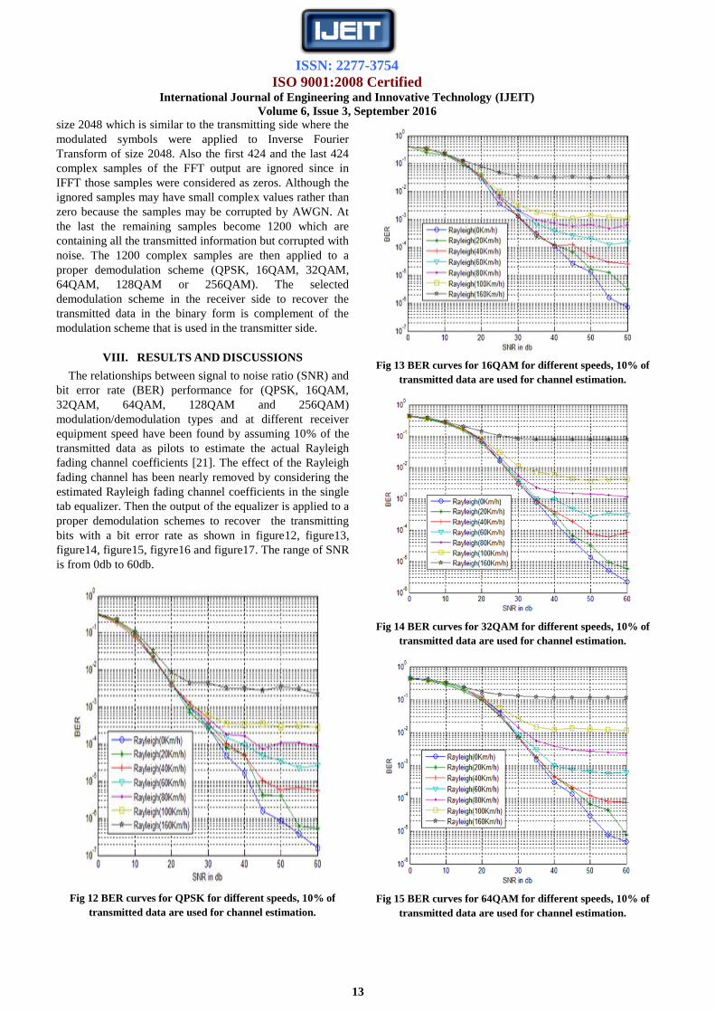
VIII. RESULTS AND DISCUSSIONS
The relationships between signal to noise ratio (SNR) and
bit error rate (BER) performance for (QPSK, 16QAM,
32QAM, 64QAM, 128QAM and 256QAM)
modulation/demodulation types and at different receiver
equipment speed have been found by assuming 10% of the
transmitted data as pilots to estimate the actual Rayleigh
fading channel coefficients [21]. The effect of the Rayleigh
fading channel has been nearly removed by considering the
estimated Rayleigh fading channel coefficients in the single
tab equalizer. Then the output of the equalizer is applied to a
proper demodulation schemes to recover the transmitting
bits with a bit error rate as shown in figure12, figure13,
figure14, figure15, figyre16 and figure17. The range of SNR
is from 0db to 60db.
Fig 12 BER curves for QPSK for different speeds, 10% of
transmitted data are used for channel estimation.
Fig 13 BER curves for 16QAM for different speeds, 10% of
transmitted data are used for channel estimation.
Fig 14 BER curves for 32QAM for different speeds, 10% of
transmitted data are used for channel estimation.
Fig 15 BER curves for 64QAM for different speeds, 10% of
transmitted data are used for channel estimation.
ISSN: 2277-3754
ISO 9001:2008 Certified International Journal of Engineering and Innovative Technology (IJEIT)
Volume 6, Issue 3, September 2016
14
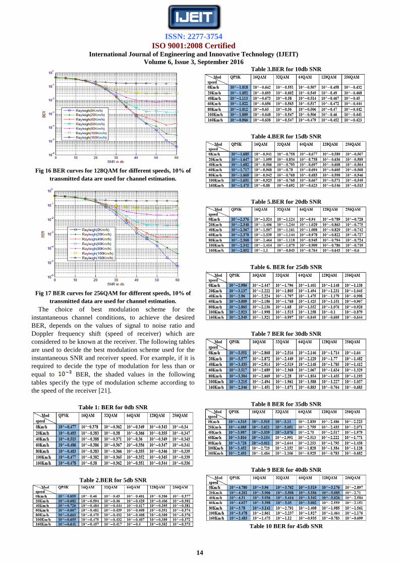
Fig 16 BER curves for 128QAM for different speeds, 10% of
transmitted data are used for channel estimation.
Fig 17 BER curves for 256QAM for different speeds, 10% of
transmitted data are used for channel estimation.
The choice of best modulation scheme for the
instantaneous channel conditions, to achieve the desired
BER, depends on the values of signal to noise ratio and
Doppler frequency shift (speed of receiver) which are
considered to be known at the receiver. The following tables
are used to decide the best modulation scheme used for the
instantaneous SNR and receiver speed. For example, if it is
required to decide the type of modulation for less than or
equal to BER, the shaded values in the following
tables specify the type of modulation scheme according to
the speed of the receiver [21].
Table 1: BER for 0db SNR
Table 2.BER for 5db SNR
Table 3.BER for 10db SNR
Table 4.BER for 15db SNR
Table 5.BER for 20db SNR
Table 6. BER for 25db SNR
Table 7 BER for 30db SNR
Table 8 BER for 35db SNR
Table 9 BER for 40db SNR
Table 10 BER for 45db SNR

ISSN: 2277-3754
ISO 9001:2008 Certified International Journal of Engineering and Innovative Technology (IJEIT)
Volume 6, Issue 3, September 2016
15
Table11 BER for 50db SNR
Table 12 BER for 55db SNR
Table 13 BER for 60db SNR
IX. CONCLUSION
Best type of modulation scheme now can be identified
according to the SNR and the speed of the receiver (Doppler
effects) of the channel. Usually for any acceptable SNR, the
QPSK modulation does not offer any problem while using
256QAM is the worst in term of BER. On the other hand
QPSK carries less information than 256QAM; therefore for
good channel conditions and low speed of receiver, high
order modulation schemes such as 32QAM 64QAM,
128QAM and 256QAM are more preferable. For example
for 10^-3 BER at the receiver in a physical layer, and for
160Km/h and 100Km/h speeds of receiver, the QPSK
modulation should be used. But for 80Km/h speed, the
QPSK and 16QAM can be used on condition that the SNR is
equal or greater than 35db. For 60Km/h speed, the 16QAM
can be used on condition that the SNR is greater than 35db,
the 32QAM and the 64QAM can be used on condition that
the SNR is greater than 40db. For 40Km/h speed, the
128QAM can be used on condition that the SNR is greater
than 40db and the 256QAM can be used on condition that
the SNR is greater than 50db. For 20Km/h and stationary
receiver, the 256QAM can be used on condition that the
SNR is greater than 45db.
.
REFERENCES [1] Chang-Joo Kim, Goo-Young Jeong, Han-Kyu Park and Sang-
sam Choi, “New Rayleigh Channel Estimator Based On
PSAM Channel sounding Technique,” ETRI, Taejeon,
Korea, 1997 IEEE, pp.1518 -1520.
[2] National Instruments, “OFDM and Multi-Channel
Communication Systems”, Publish Date: Jun 19, 2013.
[3] Mohammed AboudKadhim, Widad Ismail, “Implementation
of WIMAX IEEE802.16d Baseband Transceiver on Multi-
Core Software-Defined Radio Platform”, ISSN: 1109-2742,
Issue 5, Volume 9, May 2010.
[4] Kyongkuk Cho and Dongweon Yoon, “On the General BER
Expression of One- and Two-Dimensional Amplitude
Modulations,” IEEE Transactions on Communications, vol.
50, no.7, pp. 1074-1080, July 2002.
[5] Larry Riche, Khalil Sujaee, and Roy George, “The
performance of high order modulation QAM-OFDM in the
presence multipath fading channels”, IEEE Explore, 2012.
[6] Sridhar V., Anil Kumar M., M. Renuka, “Embedded
Universal Audio Scrambler using OFDM Technique”, ISSN:
2278-067X, Volume 1, Issue 2, PP.25-28, (May 2012).
[7] Rainer Grünheid and Hermann Rohling, “Adaptive
Modulation and Multiple Access for the OFDM Transmission
Technique”, Wireless Personal Communications 13, Kluwer
Academic Publishers, 2000.
[8] K. SeshadriSastry and M. S. Prasad Babu, “Fuzzy logic based
Adaptive Modulation Using Non Data Aided SNR Estimation
for OFDM system”, International Journal of Engineering
Science and Technology, Vol. 2(6), 2010.
[9] Arthur H. Ballard, “A New Multiplex Technique for
Communication Systems”, IEEE transactions on power
apparatus and systems, VOL. PAS-85, NO.10, October-1966.
[10] J.Faezah, and K.Sabira, “Adaptive Modulation for OFDM
Systems”, International Journal of Communication Networks
and Information Security (IJCNIS), Vol. 1, No. 2, August
2009.
[11] Sami H. O. Salih and Mamoun M. A. Suliman1,
“Implementation of Adaptive Modulation and Coding
Technique using,” International Journal of Scientific &
Engineering Research Volume2, Issue 5, pp.1-4 May-2011.
[12] Salima El Makhtari, Mohamed Moussaoui and Hassan
Samadi, “Performance Evaluation of AMC turbo Coded
OFDM for 3GPP Long Term Evolution downlink system”
978-1-4673-1520-3/12/$31.00 ©2012 IEEE.
[13] Mustafa Dh. Hassib ,“Symbol Dispersion to Represent the
Adaptive Modulation and Coding for Space-Time Block
Coded OFDM System”, Pensee Journal, ISI Thomson
Reuters, Paris/France, Vol 76, No. 4;Apr 2014.
[14] Theodore S. Rappaport, “Wireless Communication Principles
and Practice,” second edition, Prentice Hall PTR, 1996.
[15] LajosHanzo, Yosef (Jos) Akhtman and Li Wang, “MIMO-
OFDM for LTE, Wi-Fi and WiMAX”, A John Wiley and
Sons, Ltd, Publication, 2011.
[16] Erik Dahlman, Stefan Parkvall, Johan Skold and Per Beming,
“3G Evolution HSPA and LTE for Mobile Broadband”,
Published by Elsevier, 2008.
[17] Mitalee Agrawal, YudhishthirRaut, “BER Analysis of MIMO
OFDM System for AWGN & Rayleigh Fading Channel”,
International Journal of Computer Applications, Volume 34–
No.9, November 2011.

ISSN: 2277-3754
ISO 9001:2008 Certified International Journal of Engineering and Innovative Technology (IJEIT)
Volume 6, Issue 3, September 2016
16
[18] Yong Soo Cho, JaekwonKim, Won Young Yang, Chung G.
Kang, “MIMO-OFDM WIRELESS COMMUNICATIONS
WITH MATLAB”, John Wiley & Sons (Asia) Pte Ltd, 2010.
[19] Christopher Cox, “An Introduction to LTE”, A John Wiley &
Sons, Ltd., 2012.
[20] Krzysztof Wesolowski, “Mobile Communication Systems”,
JOHN WILEY & SONS, LTD, 2002.
[21] Mohammed B. Shukur, Younis M. Abbosh, “Data
Throughput Maximization Using Adaptive Modulation for
Single Carrier Base Band Transmission System”,
International Journal of Emerging Technology and Advanced
Engineering (IJETAE), Volume 4, Issue 10, pp.16-25,
October 2014).
[22] Raymond Chan, “Channel Prediction for Adaptive
Modulation in Wireless Communications”, M.Sc. dissertation
in Electrical Engineering, Virginia Polytechnic and State
University, 2003.
AUTHOR BIOGRAPHY First Author Communication Engineering Department/College of
Electronics Engineering/University of Mosul/Mosul/Iraq.
Second Author Computer Engineering Department/College of Electronics
Engineering/University of Ninveha/Mosul/Iraq


