Embed Size (px)
Citation preview
November/December 2011 www.geartechnology.com46 www.geartechnology.com November/December 2011 www.geartechnology.com November/December 2011
Management SummaryMaximization of gear transmission density is important in that it delivers increased
output torque within given dimensional constraints. This is critical, for instance, in rac-ing gearboxes or in reducing size and weight of aerospace gear drives. It can also yield reduced costs for automotive and consumer product gear trains, for example. There are several ways to increase gear drive load capacity, including advanced design, materials and technologies.
This paper presents an approach that provides optimization of both gearbox kinematic arrangement and gear tooth geometry to achieve a high-density gear transmission. It intro-duces dimensionless gearbox volume functions that can be minimized by the internal gear ratio optimization. Different gearbox arrangements are analyzed to define a minimum of the volume functions. Application of asymmetric gear tooth profiles for power density maximization is also considered.
Introduction: Volume FunctionsThe gearbox weight minimization software
(Ref. 1) defines internal gear distribution for different gear drive arrangements. However, it does not take into account the gear volume utilization, i.e., the ratio of the actual gear volume to the pitch cylinder volume. It also is not applicable to multi-branch epicyclic gear drive arrangements (Fig. 6). Load capacity or transmission density is defined by a gear tooth’s working flank surface durability, which is limited by allowable contact stress level. For a pair of mating gears, this can be described by the gear transmission density coefficient K
o
(Ref. 2) that is equal to:
(1)
where:
T1 Driving pinion torque d
w1 Pinion operating pitch diameter b
w Effective gear face width in
mesh
Gear Transmission Density Maximization
Alexander L. Kapelevich and Viacheslav M. Ananiev
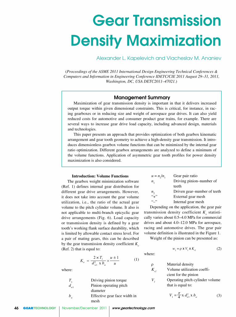
u = n2/n1 Gear pair ratio n1 Driving pinion–number of teeth n2 Driven gear–number of teeth “+” External gear mesh “–” Internal gear mesh
Depending on the application, the gear pair transmission density coefficient K
o statisti-
cally varies about 0.5–4.0 MPa for commercial drives and about 4.0–12.0 MPa for aerospace, racing and automotive drives. The gear pair volume definition is illustrated in the Figure 1.
Weight of the pinion can be presented as:
(2)where:
r Material density K
v1 Volume utilization coeffi-
cient for the pinion V
1 Operating pitch cylinder volume
that is equal to:
(3)
1
w1
2 1o
T uK
× ×d 2 x b
w u
w1 = ρ x V1 x Kv1
4 w1V1 = x d2 x bw
π
(Proceedings of the ASME 2011 International Design Engineering Technical Conferences & Computers and Information in Engineering Conference IDETC/CIE 2011 August 29–31, 2011,
Washington, DC, USA DETC2011–47021.)

www.geartechnology.com November/December 2011 www.geartechnology.com November/December 2011 47
sun gear is defined by Equation 4 with a “+” sign because the sun gear is in the external mesh with the planet gear. The planet gear operating pitch cylinder volume is defined by Equation 5. The operating pitch cylinder vol-ume of the ring gear is:
(12)
where:
dw3 Ring gear operating pitch
diameterK
bw = b
wi / b
we Effective gear face width
ratio in the epicyclic gear stageb
we Effective gear face width in
the sun/planet gear meshb
wi Effective gear face width in
the planet/ring gear mesh p = |n3 / n1| Ring/sun gear ratio in the epicyclic stagen3 Ring gear number of teethAssuming the same density material for all
gears, the total weight of gears in the epicyclic gear stage is:
(13)
where:
Kv3 Volume utilization coeffi-
cient of the sun gear;n
p Number of planet gears.
Applying Equations 5 and 12, the total weight is:
(14)
Then considering Equation 4, the epicyclic gear stage volume function is:
continued
Figure 1—Gear pair volume definition: A = external gearing; B = inter-nal gearing.
which, considering Equation 1, also can be presented as:
(4)
The operating pitch cylinder volume of the mating gear is
(5)
where: d
w2 Gear operating pitch diameter
Total weight of two mating gears is:
(6)
where: Kv1 Volume utilization coefficient of the pinion Kv2 Volume utilization coefficient of the mating gear
Then applying Equation 5:
(7)
or applying Equation 4:
(8)
where:
Fv Dimensionless volume function
For the cylindrical pair of gears the volume function is:
(9)
where:
(10)
is the pinion volume function;
(11)is the mating gear volume function.
The epicyclic gear stage volume definition is illustrated in Figure 2. In this case the sub-script indexes 1–3 (1, 2, 3) are related to the sun gear, planet gear and ring gear accordingly.
The operating pitch cylinder volume of the
1
1
12 o
T uV
K uπ ±
= × ×
2 22 2 14 w wV d b u V
π × × ×
1 2
1 1 2 2( )v v
w w w
V K V Kρ= + =
× × + ×
21 2 1 2
1( )v v v v v
uF F F K u K
u±
= + = × + ×
1 1
1v v
uF Ku
±= ×
2 2( 1)v vF u u K= ± × ×
1
2 vo
Tw F
Kπρ= × × ×
2 23 3 14 w wi bwV d b p V K
π= × × = × ×
dw2
dw1
dw1
dw2
bw
bw
A B
21 1 2( )v vw V K u Kρ= × × + ×
2 21 1 2 3( )v p v v bww V K u n K p K Kρ= × × + × × + × ×
1 2 3
1 1 2 2 3 3( )p
v p v v
w w n w wV K n V K V Kρ
×
× × × × ×

November/December 2011 www.geartechnology.com48 www.geartechnology.com November/December 2011 www.geartechnology.com November/December 2011
(15)
where:
(16)
is the sun gear volume function;
(17)
is the planet gear volume function,
(18)
is the planet gear volume function.
The more planet gears in the epicyclic gear stage, the lower its volume function and more compact the gearbox. However, the selected number of planet gears must exclude the inter-ference between them.
The volume utilization coefficients Kv
depend on the gear body shape (solid body or with central and lightening holes, rim, web, spokes, etc.) and, for driving pinions (sun gears), varies approximately in a range of 0.8–1.0; for driven (or planet) gears, 0.3–0.7; and for internal (or ring) gears, 0.05–0.1.
Unlike the convex-convex sun/planet gear contact, the planet/ring gear mesh has the convex-concave gear contact. This allows reduction of the effective gear facewidth in the planet/ring gear mesh in order to achieve a level similar to the contact stress. This typi-cally makes the effective gear face width ratio K
b < 1.0; or, typically, 0.7–0.9.When the input torque and gear ratio are
given, and the gear transmission density coef-ficient Ko is selected according to the appli-cation, volume functions allow for estimat-ing both size and weight of the gearbox at a very preliminary stage of design for different options of gear arrangement.
Volume Functions for Different Gear Arrangements
The volume functions are defined for four two-stage gear arrangements.
1. External gear arrangement (Fig. 3)The gearbox with this simple gear arrange-
ment has a minimal number of gears and bear-ings; it is less expensive in production and
dw3
dw2
dw1
bwe
bwi
OutputShaft
InputShaft
n1II
n1
n2I
n2II
n1II
n2II
n1I
n2In2
I
n2I
n2II
n1II n1
II
n1I
A
B
C
Figure 2—Epicyclic gear stage volume definition.
Figure 3—A = two-stage external gear train; B = one-transmission-branch arrangement; C = two-transmission-branch arrangement.
1 2 3
2 21 2 3
1( )
ve ve p ve ve
v p v v bwp
F F n F F
u K u n K p K Ku n
= + × + =
+× + × × + × ×
×
1 1
1ve v
p
uF K
u n+
= ××
2 2
1ve v
p
uF u Kn
= × ×
F p K K= × × × 2
3 31
ve v bwp
uu n+×
www.geartechnology.com November/December 2011 www.geartechnology.com November/December 2011 49
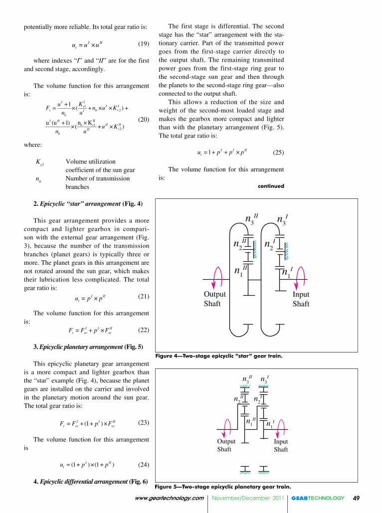
The first stage is differential. The second stage has the “star” arrangement with the sta-tionary carrier. Part of the transmitted power goes from the first-stage carrier directly to the output shaft. The remaining transmitted power goes from the first-stage ring gear to the second-stage sun gear and then through the planets to the second-stage ring gear—also connected to the output shaft.
This allows a reduction of the size and weight of the second-most loaded stage and makes the gearbox more compact and lighter than with the planetary arrangement (Fig. 5). The total gear ratio is:
(25)
The volume function for this arrangement is:
continued
potentially more reliable. Its total gear ratio is:
(19)
where indexes “I” and “II” are for the first and second stage, accordingly.
The volume function for this arrangement is:
(20)
where:
Kv3 Volume utilization
coefficient of the sun gear n
b Number of transmission
branches
2. Epicyclic “star” arrangement (Fig. 4)
This gear arrangement provides a more compact and lighter gearbox in compari-son with the external gear arrangement (Fig. 3), because the number of the transmission branches (planet gears) is typically three or more. The planet gears in this arrangement are not rotated around the sun gear, which makes their lubrication less complicated. The total gear ratio is:
(21)
The volume function for this arrangement is:
(22)
3. Epicyclic planetary arrangement (Fig. 5)
This epicyclic planetary gear arrangement is a more compact and lighter gearbox than the “star” example (Fig. 4), because the planet gears are installed on the carrier and involved in the planetary motion around the sun gear. The total gear ratio is:
(23)
The volume function for this arrangement is
(24)
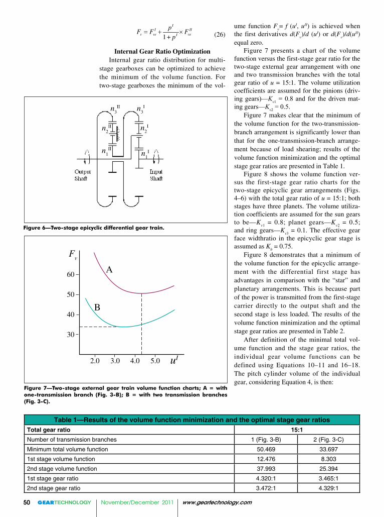
4. Epicyclic differential arrangement (Fig. 6)
I IItu u u= ×
1
2
12
1( )
( 1)( )
III Iv
v b vIb
III IIII IIb v
vIIb
KuF n u K
n u
n Ku uu K
n u
+= × + × × +
×+× + ×
I IItu p p= ×
I I IIv ve veF F p F= + ×
(1 ) (1 )I IItu p p= + × +
(1 )I I IIv ve veF F p F= + + ×
OutputShaft
InputShaft
n3In3
II
n2II n2
I
n1II n1
I
Figure 4—Two-stage epicyclic “star” gear train.
OutputShaft
InputShaft
n3In3
II
n2II n2
I
n1II
n1I
Figure 5—Two-stage epicyclic planetary gear train.
1 I I IItu p p p= + + ×
November/December 2011 www.geartechnology.com50 www.geartechnology.com November/December 2011 www.geartechnology.com November/December 2011
(26)
Internal Gear Ratio OptimizationInternal gear ratio distribution for multi-
stage gearboxes can be optimized to achieve the minimum of the volume function. For two-stage gearboxes the minimum of the vol-
ume function Fv= f (uI, uII) is achieved when
the first derivatives d(Fv)/d (uI) or d(F
v)/d(uII)
equal zero.Figure 7 presents a chart of the volume
function versus the first-stage gear ratio for the two-stage external gear arrangement with one and two transmission branches with the total gear ratio of u = 15:1. The volume utilization coefficients are assumed for the pinions (driv-ing gears)—Kv1 = 0.8 and for the driven mat-ing gears—Kv2 = 0.5.
Figure 7 makes clear that the minimum of the volume function for the two-transmission-branch arrangement is significantly lower than that for the one-transmission-branch arrange-ment because of load shearing; results of the volume function minimization and the optimal stage gear ratios are presented in Table 1.
Figure 8 shows the volume function ver-sus the first-stage gear ratio charts for the two-stage epicyclic gear arrangements (Figs. 4–6) with the total gear ratio of u = 15:1; both stages have three planets. The volume utiliza-tion coefficients are assumed for the sun gears to be—K
v1 = 0.8; planet gears—Kv2 = 0.5;
and ring gears—Kv3 = 0.1. The effective gear
face widthratio in the epicyclic gear stage is assumed as K
b = 0.75.
Figure 8 demonstrates that a minimum of the volume function for the epicyclic arrange-ment with the differential first stage has advantages in comparison with the “star” and planetary arrangements. This is because part of the power is transmitted from the first-stage carrier directly to the output shaft and the second stage is less loaded. The results of the volume function minimization and the optimal stage gear ratios are presented in Table 2.
After definition of the minimal total vol-ume function and the stage gear ratios, the individual gear volume functions can be defined using Equations 10–11 and 16–18. The pitch cylinder volume of the individual gear, considering Equation 4, is then:
Table 1—Results of the volume function minimization and the optimal stage gear ratiosTotal gear ratio 15:1Number of transmission branches 1 (Fig. 3-B) 2 (Fig. 3-C)
Minimum total volume function 50.469 33.697
1st stage volume function 12.476 8.303
2nd stage volume function 37.993 25.394
1st stage gear ratio 4.320:1 3.465:1
2nd stage gear ratio 3.472:1 4.329:1
Figure 7—Two-stage external gear train volume function charts; A = with one-transmission branch (Fig. 3-B); B = with two transmission branches (Fig. 3-C).
Fv
A
B
60
50
40
30
2.0 3.0 4.0 5.0 uI
1
II II
v ve veI
pF F F
p ×
+
n3II n3
I
n2II n2
I
n1II
n1I
Figure 6—Two-stage epicyclic differential gear train.

www.geartechnology.com November/December 2011 www.geartechnology.com November/December 2011 51
continued
(27)
From here:
(28)or:
(29)
where:
Kv Volume utilization
coefficienty= b
w/d
w Aspect ratio that
varies in a range of 0.05–1.2 or higher (Ref. 2)
This allows definition of all the gear diameters and size of all gears in assembly. However, the total volume and weight of the gearbox is not in direct proportion to its volume function. The share of the gear vol-ume and weight is usually higher for simple arrangements like the external gear train. In a more complicated epicyclic gear arrangement, this share could be much lower because of a higher number and volume of other gear-box parts and components, such as carriers, bearings, shafts, lubrication system parts, etc. Statistical data of the gear volume share for the selected type of gear arrangement allow one to define the approximate size of the gearbox. In many cases, the gearbox is built in the overall mechanism assembly, and minimization of its size and weight should be considered to achieve optimum operating characteristics of the whole product, including, for example, cost, lifetime, noise and vibration.
The approach utilizing the volume func-tions allows estimation of the volume and weight of the gearbox for any multi-stage arrangement in a very early stage of prod-
Fve A
B
15
10
5
2.0 3.0 4.0 pI
C
Figure 8—Two-stage epicyclic gear train volume function charts; A = “star” arrangement (Fig. 4); B = planetary (Fig. 5); C = with first differential stage (Fig. 6).
1
02 v
TV F
Kπ
= × ×
2 1
0
24w w v
v
Td b V F
K Kπ×
× = × = ××
1
3
0
2 vw
v
T Fd
K K ψ× ×
=× ×
Table 2—Results of the volume function minimization and the optimal stage gear ratiosTotal gear ratio 15:1Gear arrangement ( Fig. 8) A B C
Min. total volume function 14.32 9.66 4.09
1st stage volume function 3.22 2.03 2.24
2nd stage volume function 11.09 7.63 1.85
1st stage planet/sun gear ratio 1.55:1 0.97:1 1.09:1
2nd stage planet/sun gear ratio 1.33:1 0.91:1 1.20:1
1st stage ring/sun gear ratio 4.11:1 2.93:1 3.19:1
2nd stage ring/sun gear ratio 3.65:1 2.82:1 3.40:1
uct development. The next phase of gearbox design includes the gear and other component parameter calculation, and stress analysis pro-duces a more accurate definition of the volume and weight of the gearbox.
Gear Tooth Geometry for Higher Transmission Density
In most high-load-capacity gear transmis-sions, the tooth load on one flank is signifi-cantly higher and is applied for longer periods of time than for the opposite one; this creates the possibility of using gears with asymmetric teeth (Ref. 3).
The design intent of asymmetric gear teeth is to improve performance of the primary drive profiles at the expense of performance of the opposite coast profiles. The coast profiles are unloaded or lightly loaded during a relative-ly short work period. Asymmetric tooth pro-
November/December 2011 www.geartechnology.com52 www.geartechnology.com November/December 2011 www.geartechnology.com November/December 2011
• Application of gears with asymmetric teeth provides enhanced gear drive transmission density.
References 1. Gearbox weight minimization software: UTS 580 system.2. Vulgakov, E.B. et al. Aviation Gearboxes Handbook, published by Machine Building, Moscow, 1981.3. Kapelevich, A.L. “Geometry and Design of Involute Spur Gears with Asymmetric Teeth,” Mechanism and Machine Theory, 2000, Issue 35, pp. 117–130.4. Brown, F.W., S.R. Davidson, D.B. Hanes, D.J. Weires and A.L. Kapelevich. “Analysis and Testing of Gears with Asymmetric Involute Tooth Form and Optimized Fillet Form for Potential Application in Helicopter Main Drives,” Gear Technology, June/July 2011, 46–55.5. Novikov, A.S., A.G. Paikin, V.L. Dorofeyev, V.M. Ananiev and A.L. Kapelevich. “Application of Gears with Asymmetric Teeth in Turboprop Engine Gearbox,” Gear Technology, January/February 2008, 60–65.
Alexander L. Kapelevich is a gear design con-sultant at AKGears, LLC, Shoreview, Minnesota. He holds a Ph.D. in mechanical engineering, Moscow State Technical University and a MS in mechanical engineering from Moscow Aviation Institute. He is a developer of the trademarked Direct Gear Design methodology, which has been implemented in many custom gear drives for a variety of applications. Kapelevich is the author of numerous technical publications and patents, and is a member of the AGMA Aerospace and Plastic Gearing Committees, SME, ASME and SAE International.
files also make it possible to simultaneously increase the contact ratio and operating pres-sure angle beyond conventional gears’ limits. The main advantage of asymmetric gears is reduction of gear dimensions while maintain-ing the allowable contact stress level, result-ing in higher transmission density coefficient K
o. Asymmetric gear testing at the rotorcraft
division of the Boeing Company demonstrated superior scoring performance when compared to conventional (baseline) symmetric gears. The mean value for a limited data set showed an improvement of approximately 25% (Ref. 4).
The combination of the volume function approach and gears with asymmetric teeth achieved extremely high power density in the turboprop engine gearbox (Ref. 5).
Summary• The dimensionless volume functions
were introduced and correlated to gear transmission density.
• The gear train volume functions are described and defined for the gear pair and epicyclic gear stage.
• Different two-stage gear train arrangement volume functions were
analyzed to find their minimum and optimal stage gear ratio distribution.
Viacheslav M. Ananiev is a lead scientific researcher of the Central Institute of Aviation Motors (CIAM), Moscow, Russia. With Ph.D. and MS degrees in mechanical engineering from Moscow State Technical University, Ananiev is a prominent and longtime gear expert in the Russian aerospace industry—particularly in mechanical drive systems—and author of many technical publications.