Embed Size (px)
Citation preview

Supporting information
Substituting copolymeric poly(alkylenetetrasulfide) for elemental sulfur
to diminish the shuttling effect of modified intermediate polysulfides for
high-performance lithium-sulfur batteries
He Zhou,1 Faqi Yu,1 Min Wei,1 Yunlan Su,2 Yuchen Ma,1 Dujin wang,2 Qiang Shen1*
(Corresponding E-mail: [email protected])
Experimental:
Materials and sample preparation
All the chemicals such as sublimed sulfur (S8), dichloromethane (CH2Cl2) and dichloroethane
(ClCH2CH2Cl) are of analytical grade and were used as purchased. Ultrapure water (18.2 MΩ·cm)
was used throughout solution preparation.
Synthesis and characterization of serial copolymeric poly(alkylenetetrasulfide) with the formula of
[(CH2)yS4]n (y = 1 or 2; n ~ the number of repeating units) have been well demonstrated in
literatures.1-4 At first, yellow-orange aqueous solution of sodium tetrasulfide (Na2S4) was obtained by
the stoichiometric reaction of aqueous NaOH and molecular S8, and then aqueous Na2S4 (50 mL) was
transferred into a 100-mL three-necked round bottom flask equipped with a dropping funnel,
condenser and thermometer. Subsequently, CH2Cl2 or ClCH2CH2Cl liquid (2 mL) was dropwise
added into the aqueous Na2S4-containing flask at 40C, and then a condensation polymerization
reaction proceeded under vigorous stirring, shown as the following equation (1):
(1)2nNaCl]S)[(CHSnNaCl)nCl(CH n4y242y2
Electronic Supplementary Material (ESI) for ChemComm.This journal is © The Royal Society of Chemistry 2019

Finally, at a reaction interval of 2 h, a lumpy mass of linear copolymer poly(methylenetetrasulfide)
or poly(ethylenetetrasulfide), abbreviated as PMTS or PETS, was taken out of the reaction system and
was thoroughly washed with hot water.
Chitosan-derived porous carbon (CPC) was self-made in laboratory, and this guaranteed both the
graphitization of framework CPC and its mainly microporous feature as demonstrated previously.5,6
The dispersion of a polymer PMTS/PETS in carbon disulfide (CS2) or the solution of molecular S8 in
CS2 was thoroughly soaked into CPC, resulting in a copolymer-containing or sulfur-encapsulated
composite after the complete evaporation of the solvent. To assay the better cycling performance of a
copolymer/CPC composite than that of composite S/CPC, the effective S-content in each composite
was kept at a constant value of ~40 wt%.2,7-9
Structural and electrochemical characterization
Fourier transform infrared spectroscopy (FT IR) data was obtained on a VERTEX-70 spectrometer
using KBr tablet method. Nitrogen adsorption isotherms were measured on a micromeritics ASAP
2020 porosimeter at 77 K using a 10 s equilibrium interval. X-ray diffraction (XRD) patterns were
recorded on a Rigaku D/max 2400 kV powder X-ray diffractometer with Cu Ka radiation (λ=1.5406 Å,
40 kV, 120 mA) in the 2Theta range of 10 and 70. Raman spectra were measured using a 632.8 nm
laser with a LABRAM-HR confocal laser micro-Raman spectrometer. Thermogravimetric analysis
(TGA) profiles were obtained on a Mettler Toledo TGA/SDTA851 machine with a heating rate of 10
℃ min-1 under N2 atmosphere. Samples were dispersed in ethanol by ultrasonication and then
deposited on a carbon film supported by copper grid, prior to transmission electron microscopy (TEM)
and high-resolution TEM (HR TEM) measurements on a JEM 2100 microscope (200 kV). Scanning
electron microscopy (SEM) was carried out with a JEOL JSM-6700F combined X-ray energy
dispersive spectroscopy (EDS). X-ray photoelectron spectroscopy (XPS) analysis was performed on a
VG Scientific ESCALAB 220i-XL electron spectrometer using Al K radiation.
Cathode material (e.g., PMTS/CPC composite), acetylene black and sodium alginate binder were
mixed in water at a mass ratio of 7.0:1.5:1.5, and the resulting slurry was pasted onto an aluminum
foil and dried at 60C for 12 h. And then, the aluminum foil was cut into discs (12 mm in diameter)
and used as working electrodes with a mass loading of 1.4 0.4 mg cm-2. Lithium foil, Celgard 2300
polymeric film and nickel foam were used as counter electrode, separator and current collector,
respectively. An electrolyte solution (35 L) of lithium bis(trifluoromethanesulfonyl)imide (LiTFSI,
1.0 M) and LiNO3 (2.0 %) in the mixed solvent of 1,3-dioxanes and 1,2-dimethoxyethane (1:1, vol:vol)
was used to assemble 2032-type coin cells in an argon-filled glove box.
Galvanostatic cycling tests were conducted on a Land CT2001A battery system at 30C between
1.8-2.7 V (vs. Li+/Li and hereafter). Cyclic voltammetry (CV) curves were recorded using an LK
2005A electrochemical workstation at 0.1 mV s-1 within 1.5-3.0 V. Electrochemical impedance
spectroscopy (EIS) data was obtained by an EG&G PAR 273A electrochemical workstation in the
frequency range of 0.1 MHz - 0.01 Hz with an AC voltage amplitude of 5 mV.
Theoretical calculationTheoretical calculations were performed using the Vienna Ab-initio Simulation Package (VASP)
and the exchange-correlation term was the standard generalized gradient approximation (GGA) of
Perdew-Burke-Ernzerhof (PBE) functionals.10,11 In view of the highly microporous nature of
graphitized CPC framework, its single-layer graphene-like surface was defined as a polyaromatic
hydrocarbon molecule containing 24 carbon atoms and 12 hydrogen atoms. The binding energy (Eb)
between one lithium polysulfide (e.g., Li2Sn, n = 4 or 6) and the graphene-like surface of graphitized
CPC was etimated according to the expression of . 21totalb EEEE
Wherein, E1, E2 and Etotal represent the energies of lithium polysulfide, single-layer graphene and
their integrative configuration of Li2Sn-CPC system, respectively. To simplify the calculation, van der
Waals (vdW) interactions within density functional theory (DFT) were focused, and a plane-wave
basis set at the kinetic energy cutoff of 400 eV was employed until the value of residual forces is
smaller than 0.02 eV Å-1.12

Fig. S1 FT IR spectra of as-synthesized PMTS and PETS copolymers, showing the characteristic
adsorptions of S-S (450-466 cm-1), C-S (640-870 cm-1), C-H bending (1050-1450 cm-1)
By comparison, along with the change of PMTS to PETS, the blue shift of C-H bending and the red
shift of C-H stretching are observed, which may be attributed to the increasing number of methylene
(-CH2-) for the non-sulfur segments in these copolymeric backbones.
Fig. S2 (a) N2 adsorption-desorption isotherms and (b) pore size distributions of pristine CPC and
composite PMTS/CPC, and an inset in panel (d) presents the microspore size distribution of CPC.
Pristine porous carbon (CPC) has a high specific surface area of 2225.8 m2 g-1 (the microporous
fraction ~ 1388.0 m2 g-1) and a total pore volume of 1.16 cm3 g-1 (the micropore size distribution, 0.5 -
1.2 nm; the microporous volume, 0.55 cm3 g-1), and by comparison the specific surface area and
average pore size of composite PMTS/CPC or PETS/CPC are too small to be omitted.

Fig. S3 (a, b) XRD patterns and (c, d) Raman spectra of pristine CPC, as-synthesized copolymer
PMTS or PETS and composite PMTS/CPC or PETS/CPC.
XRD patterns and Raman spectra of composites PMTS/CPC and PETS/CPC only reveal the
typical characteristics of a partially graphitized carbon, indicating the “homogeneous” distribution of
polymer PMTS (or PETS) within the porous framework of CPC.
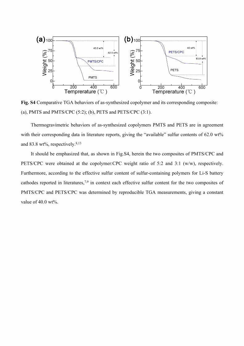
Fig. S4 Comparative TGA behaviors of as-synthesized copolymer and its corresponding composite:
(a), PMTS and PMTS/CPC (5:2); (b), PETS and PETS/CPC (3:1).
Thermogravimetric behaviors of as-synthesized copolymers PMTS and PETS are in agreement
with their corresponding data in literature reports, giving the “available” sulfur contents of 62.0 wt%
and 83.8 wt%, respectively.8,13
It should be emphasized that, as shown in Fig.S4, herein the two composites of PMTS/CPC and
PETS/CPC were obtained at the copolymer:CPC weight ratio of 5:2 and 3:1 (w/w), respectively.
Furthermore, according to the effective sulfur content of sulfur-containing polymers for Li-S battery
cathodes reported in literatures,7,9 in context each effective sulfur content for the two composites of
PMTS/CPC and PETS/CPC was determined by reproducible TGA measurements, giving a constant
value of 40.0 wt%.

Fig. S5 (a) SEM images of pristine CPC, (b) SEM and (c) corresponding C, N, O and S elemental
mapping images of PMTS/CPC composite.
Self-made framework of CPC belongs to a three-dimensional (3D) macro-/micro-porous
structure (Fig.S5), and its electron-conductive nature mainly depends upon the clustering and
orientation of sp2-hybrided carbon sites. As shown in Fig.S3, the actual graphitization of porous
framework CPC could be explained by both the small sp2-carbon domains (e.g., 5 nm) with a
disordered arrangement and the large structural domains (e.g., 1 m) with a parallel
arrangement.2,5,7,14-17

Fig. S6 (a) A high-resolution SEM image and its inserted overview of PETS/CPC composite. (b) SEM
and (c) corresponding C, S, N and O elemental mapping images of PETS/CPC composite.
As shown in Fig.S5 or S6, the thoroughly mixing of PMTS or PETS with porous framework CPC
guarantees the homogeneous distribution of elemental S or C therein.
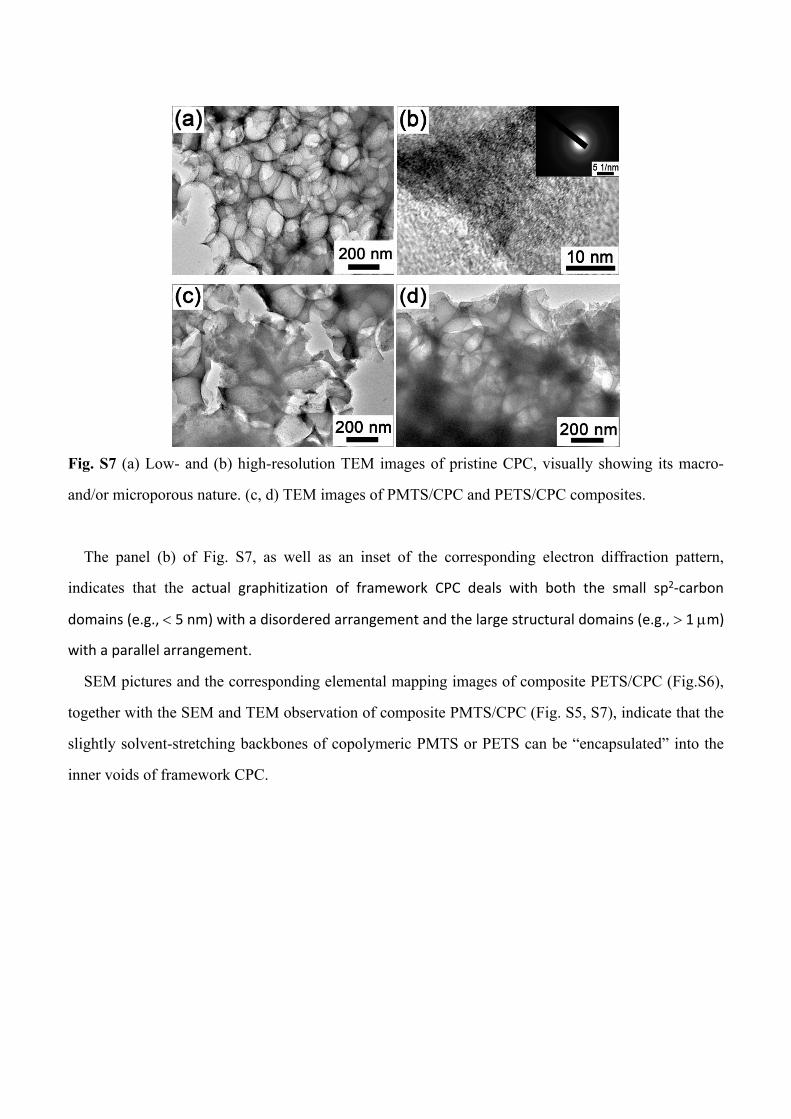
Fig. S7 (a) Low- and (b) high-resolution TEM images of pristine CPC, visually showing its macro-
and/or microporous nature. (c, d) TEM images of PMTS/CPC and PETS/CPC composites.
The panel (b) of Fig. S7, as well as an inset of the corresponding electron diffraction pattern,
indicates that the actual graphitization of framework CPC deals with both the small sp2-carbon
domains (e.g., 5 nm) with a disordered arrangement and the large structural domains (e.g., 1 m)
with a parallel arrangement.
SEM pictures and the corresponding elemental mapping images of composite PETS/CPC (Fig.S6),
together with the SEM and TEM observation of composite PMTS/CPC (Fig. S5, S7), indicate that the
slightly solvent-stretching backbones of copolymeric PMTS or PETS can be “encapsulated” into the
inner voids of framework CPC.

Fig. S8 Voltage profiles of S/CPC, PMTS/CPC and PETS/CPC composite electrodes operated at a
current density of 0.2 C (1 C = 1675 mAh g-1) within the voltage range of 1.8 - 2.7 V vs. Li+/Li.
Insofar as the 2nd discharge curve of each composite cathode is concerned, composites S/CPC and
PMTS/CPC display two discharge plateaus at the first/second voltages of 2.32/2.08 and 2.31/2.09 V,
respectively, whereas composite PETS/CPC interestingly presents three discharge plateaus at the
first/second/third voltages of 2.34/2.15/2.08 V. These voltage profiles of composite cathodes S/CPC,
PMTS/CPC and PETS/CPC coincide well with their CV behaviors (Fig. 2a-c) correspondingly.
Because the second discharge-voltage platform of PETS/CPC is too small to be negligible or
may be integrated into the first discharge-voltage platform, the shape of the discharge curves of
composite PETS/CPC is similar to that of PMTS/CPC or S/CPC.
As for the lithiation and PETS, the modified Li2S6-like intermediate is Li2S4CH2CH2 in chemical
formula, while the chemical formula of Li2S4-like polysulfide is Li2S2CH2CH2. According to the
experimental design and assumption listed in context, herein the Li2S4-like polysulfide of
Li2S2CH2CH2 is electrochemically stable or cannot be further lithiated to produce Li2S3-like
intermediate. That is, herein the intermediate Li2S3 or the products Li2S2/Li2S originate from the long-
chain polysulfides (e.g., Li2S8-like form of Li2S6CH2CH2).
Therefore, the modification of an intermediate polysulfide (e.g., only the one modified Li2S4 of Li-
S-CH2CH2-S-Li, PETS) may influence the capacity ratio. By estimation, herein the capacities from
PETS to Li-S-CH2CH2-S-Li and from Li-S-CH2CH2-S-Li to Li-S-Li are 360 and 1113 mAh g-1, the
capacity ratio between PETS to Li-S-CH2CH2-S-Li and Li-S-CH2CH2-S-Li to Li-S-Li is 1:3.1.

References
1 M. R. Kalaee, M. H. N. Famili and H. Mahdavi, Macromol. Symp., 2009, 277, 81-86.2 M. R. Kalaee, M. H. N. Famili, M. Dadgar, M. R. T. B. Olyai and A. Naderi, Phosphorus, Sulfur,
Silicon and the Relat. Elem., 2010, 185, 588-594.3 H. S. Nasrabadi, M. R. Kalaee, M. Abdouss, M. Sheydaei and S. Mazinani, J. Inorg. and
Organomet. Polym. Mater., 2013, 23, 950-957.4 H. S. Nasrabadi, M. R. Kalaee, S. Mazinani, M. Abdouss and N. Sedaghat, Polym. Plast. Technol.
Eng., 2014, 53, 767-774.5 H. Zhang, D. Jia, Z. Yang, F. Yu, Y. Su, D. Wang and Q. Shen, Carbon, 2017, 122, 547-555.6 D. Jia, Z. Yang, H. Zhang, F. Liu and Q. Shen, J. Alloys Compd., 2018, 746, 27-35.7 B.-C. Yu, J.-W. Jung, K. Park and J. B. Goodenough, Energy Environ. Sci., 2017, 10, 86-90.8 M. R. Kalaee, M. H. N. Famili, H. Mahdavi and A. Naderi, Polym. Sci. Ser. B, 2010, 52, 286-291.9 S. Zeng, L. Li, L. Xie, D. Zhao, N. Zhou, N. Wang and S. Chen, Carbon, 2017, 122, 106-113.10 G. Kresse and J. Furthmüller, Phys. Rev. B, 1996, 54, 11169-11186.
11 G. Kresse and J. Furthmüller, Comput. Mater. Sci., 1996, 6, 15-20.12 S. Grimme, J. Comput. Chem. 2006, 27, 1787-1799.13 M.R. Kalaee, M.H.N. Famili, M. Dadgar, M.R.T.B. A. Olyai, Sulfur Silicon Relat. Elem. 2010,
185: 588-594.14 X. Ji, K. T. Lee and L. F. Nazar, Nat. Mater., 2009, 8, 500-506.15 M. Chen, S. Jiang, C. Huang, X. Wang, S. Cai, K. Xiang, Y. Zhang and J. Xue, ChemSusChem,
2017, 10, 1803-1812.16 S. Osswald, J. Chmiola and Y. Gogotsi, Carbon, 2012, 50, 4880-4886.
17 M. Pawlyta, J.-N. Rouzaud and S. Duber, Carbon, 2015, 84, 479-490.