Embed Size (px)
Citation preview
8/12/2019 02 - Current TFs, Voltage TFs & Shunts
http://slidepdf.com/reader/full/02-current-tfs-voltage-tfs-shunts 1/32
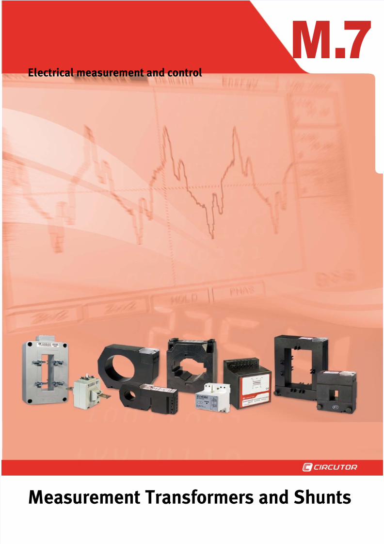
Electrical measurement and control
M.7
Measurement Transformers and Shunts
8/12/2019 02 - Current TFs, Voltage TFs & Shunts
http://slidepdf.com/reader/full/02-current-tfs-voltage-tfs-shunts 2/32
M.7Measurement Transformers and Shunts
7-2
M.7 - Measurement Transformers and Shunts
Introduction · · · · · · · · · · · · · · · · · · · · · · · · · · · · · · · · · · · · · · · · · · · · · · · · · · · · · · · · · · · · · · · · · · · · · · · · · · · · · · · · · · · · · · · · · · · · · · · · 3
Product selection table · · · · · · · · · · · · · · · · · · · · · · · · · · · · · · · · · · · · · · · · · · · · · · · · · · · · · · · · · · · · · · · · · · · · · · · · · · · · · · · · · · · · · 6
serie TC
Narrow-prole current transformer · · · · · · · · · · · · · · · · · · · · · · · · · · · · · · · · · · · · · · · · · · · · · · · · · · · · · · · · · · · · · · · · · · · · · · · · · · · · · · · · · 7
serie TCH
Top-performance current transformer · · · · · · · · · · · · · · · · · · · · · · · · · · · · · · · · · · · · · · · · · · · · · · · · · · · · · · · · · · · · · · · · · · · · · · · · · · · · · · 10
serie TA
Large-scale current transformer · · · · · · · · · · · · · · · · · · · · · · · · · · · · · · · · · · · · · · · · · · · · · · · · · · · · · · · · · · · · · · · · · · · · · · · · · · · · · · · · · · 12
serie TP
Split-core current transformer · · · · · · · · · · · · · · · · · · · · · · · · · · · · · · · · · · · · · · · · · · · · · · · · · · · · · · · · · · · · · · · · · · · · · · · · · · · · · · · · · · · · 14
serie TA 210
High-accuracy wound primary current transformer · · · · · · · · · · · · · · · · · · · · · · · · · · · · · · · · · · · · · · · · · · · · · · · · · · · · · · · · · · · · · · · · · · · · 17
serie TM 45
Wound primary current transformer · · · · · · · · · · · · · · · · · · · · · · · · · · · · · · · · · · · · · · · · · · · · · · · · · · · · · · · · · · · · · · · · · · · · · · · · · · · · · · · 18
serie TW 25
Entrance bar current transformer · · · · · · · · · · · · · · · · · · · · · · · · · · · · · · · · · · · · · · · · · · · · · · · · · · · · · · · · · · · · · · · · · · · · · · · · · · · · · · · · · 19
serie TC 020 / TC 420
Narrow-prole current transformer with a built-in converter, with an output of 0...20 mA / 4...20 mA · · · · · · · · · · · · · · · · · · · · · · · · · · · · · · ·
20
serie TP 420
Split-core current transformer with built-in converter · · · · · · · · · · · · · · · · · · · · · · · · · · · · · · · · · · · · · · · · · · · · · · · · · · · · · · · · · · · · · · · · · · · 22
serie TI 420
Large-scale current transformer with built-in converter · · · · · · · · · · · · · · · · · · · · · · · · · · · · · · · · · · · · · · · · · · · · · · · · · · · · · · · · · · · · · · · · · 24
serie TCB 420
Large-scale current transformer with built-in converter · · · · · · · · · · · · · · · · · · · · · · · · · · · · · · · · · · · · · · · · · · · · · · · · · · · · · · · · · · · · · · · · · 25
serie TCM 420
Current transformer for DIN rails with built-in converter · · · · · · · · · · · · · · · · · · · · · · · · · · · · · · · · · · · · · · · · · · · · · · · · · · · · · · · · · · · · · · · · 26
serie SH
Shunt to measure DC in high amperages · · · · · · · · · · · · · · · · · · · · · · · · · · · · · · · · · · · · · · · · · · · · · · · · · · · · · · · · · · · · · · · · · · · · · · · · · · ·
27
serie VT
Voltage transformers · · · · · · · · · · · · · · · · · · · · · · · · · · · · · · · · · · · · · · · · · · · · · · · · · · · · · · · · · · · · · · · · · · · · · · · · · · · · · · · · · · · · · · · · · · 29
serie TE
Transformer used to increase the impedance · · · · · · · · · · · · · · · · · · · · · · · · · · · · · · · · · · · · · · · · · · · · · · · · · · · · · · · · · · · · · · · · · · · · · · · · 30
serie TSR
Current adding transformers, xed on a DIN rail · · · · · · · · · · · · · · · · · · · · · · · · · · · · · · · · · · · · · · · · · · · · · · · · · · · · · · · · · · · · · · · · · · · · · · 30
Relation between products and accessories · · · · · · · · · · · · · · · · · · · · · · · · · · · · · · · · · · · · · · · · · · · · · · · · · · · · · · · · · · · · · · · · 31
8/12/2019 02 - Current TFs, Voltage TFs & Shunts
http://slidepdf.com/reader/full/02-current-tfs-voltage-tfs-shunts 3/32
Measurement Transformers and Shunts .7M
M7-3
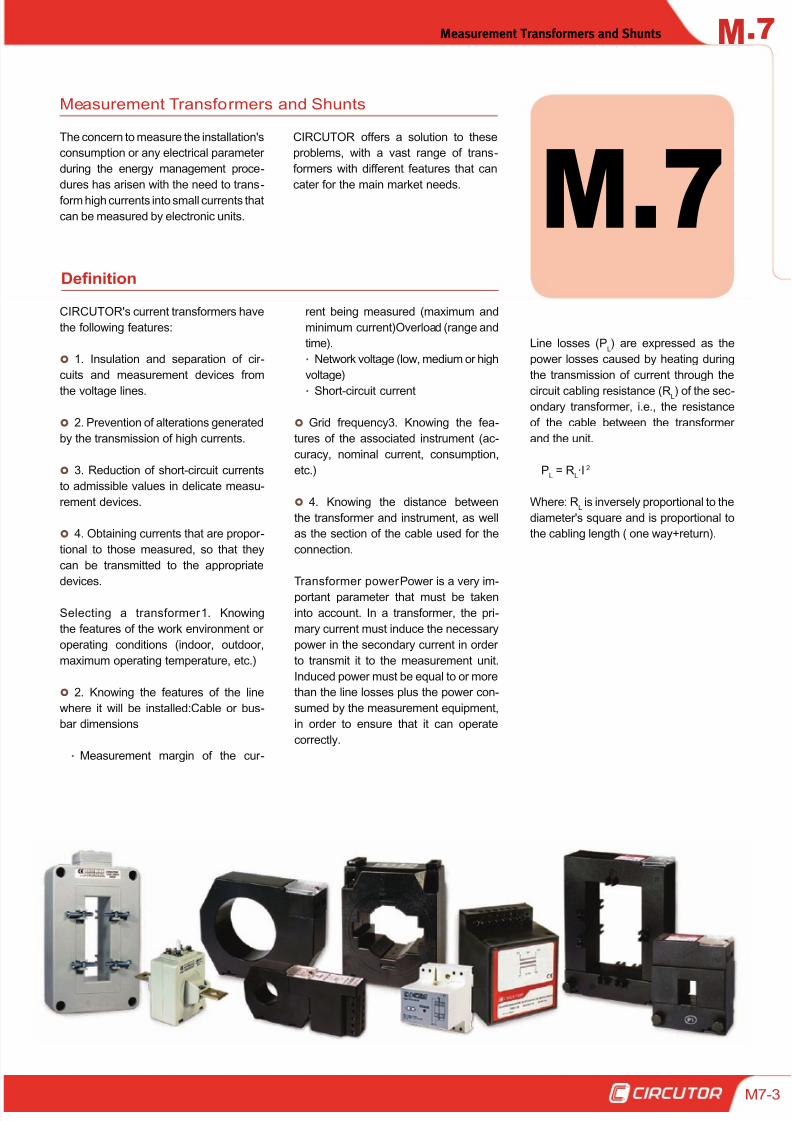
The concern to measure the installation's
consumption or any electrical parameter
during the energy management proce-
dures has arisen with the need to trans-
form high currents into small currents that
can be measured by electronic units.
Measurement Transformers and Shunts
M.7Definition
CIRCUTOR's current transformers have
the following features:
1. Insulation and separation of cir -
cuits and measurement devices from
the voltage lines.
2. Prevention of alterations generated
by the transmission of high currents.
3. Reduction of short-circuit currents
to admissible values in delicate measu-
rement devices.
4. Obtaining currents that are propor -
tional to those measured, so that they
can be transmitted to the appropriate
devices.
Selecting a transformer 1. Knowing
the features of the work environment or
operating conditions (indoor, outdoor,
maximum operating temperature, etc.)
2. Knowing the features of the line
where it will be installed:Cable or bus-
bar dimensions
Measurement margin of the cur -
rent being measured (maximum and
minimum current)Overload (range and
time).
Network voltage (low, medium or high
voltage)
Short-circuit current
Grid frequency3. Knowing the fea-
tures of the associated instrument (ac-
curacy, nominal current, consumption,
etc.)
4. Knowing the distance between
the transformer and instrument, as well
as the section of the cable used for the
connection.
Transformer power Power is a very im-
portant parameter that must be taken
into account. In a transformer, the pri-
mary current must induce the necessary
power in the secondary current in order
to transmit it to the measurement unit.
Induced power must be equal to or more
than the line losses plus the power con-
sumed by the measurement equipment,
in order to ensure that it can operate
correctly.
Line losses (PL) are expressed as the
power losses caused by heating during
the transmission of current through the
circuit cabling resistance (RL) of the sec-ondary transformer, i.e., the resistance
of the cable between the transformer
and the unit.
PL = R
L·I 2
Where: RL is inversely proportional to the
diameter's square and is proportional to
the cabling length ( one way+return).
CIRCUTOR offers a solution to these
problems, with a vast range of trans-
formers with different features that can
cater for the main market needs.
8/12/2019 02 - Current TFs, Voltage TFs & Shunts
http://slidepdf.com/reader/full/02-current-tfs-voltage-tfs-shunts 4/32
.7 Measurement Transformers and ShuntsM
7-4
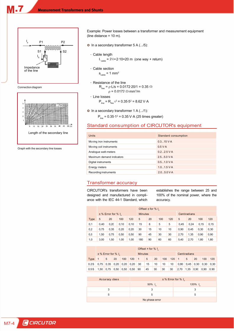
Example: Power losses between a transformer and measurement equipment
(line distance = 10 m).
In a secondary transformer 5 A (.../5):
Cable lengthx
Cable sectionx
Resistance of the linex
Line lossesx
In a secondary transformer 1 A (.../1):
Pline = 0.35·12 = 0.35 V·A (25 times greater)
Connection diagram
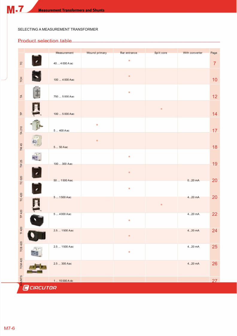
Graph with the secondary line losses
Units Standard consumption
Moving iron instruments 0.3...15 V·A
Moving coil instruments 0.5 V·A
Analogue watt-meters 0.2...2.5 V·A
Maximum demand indicators 2.5...5.0 V·A
Digital instruments 0.5...1.0 V·A
Energy meters 1.0...1.5 V·A
Recording instruments 2.0...5.0 V·A
CIRCUTOR's transformers have been
designed and manufactured in compli-
ance with the IEC 44-1 Standard, which
Type
± % Error for % In
Offset ± for % In
Minutes Centiradians
5 20 100 120 5 20 100 120 5 20 100 120
0,1 0,40 0,20 0,10 0,10 15 8 5 5 0,45 0,24 0,15 0,15
0,2 0,75 0,35 0,20 0,20 30 15 10 10 0,90 0,45 0,30 0,30
0,5 1,50 0,75 0,50 0,50 90 45 30 30 2,70 1,35 0,90 0,90
1,0 3,00 1,50 1,00 1,00 180 90 60 60 5,40 2,70 1,80 1,80
Type
± % Error for % In
Offset ± for % In
Minutes Centiradians
1 5 20 100 120 1 5 20 100 120 1 5 20 100 120
0.2 S 0,75 0,35 0,20 0,20 0,20 30 15 10 10 10 0,90 0,45 0,30 0,30 0,30
0.5 S 1,50 0,75 0,50 0,50 0,50 90 45 30 30 30 2,70 1,35 0,90 0,90 0,90
Accur acy clas s ± % Error for % In
50% In
120% In
3 3 3
5 5 5
No phase error
Impedanceof the line
Ip P1 P2
S1 S2
IS
RL
Length of the secondary line
Standard consumption of CIRCUTOR's equipment
Transformer accuracy
establishes the range between 25 and
100% of the nominal power, where the
accuracy.
Lcable
= 2·I= 2·10=20 m (one way + return)
Pline = R
line·I2 = 0.35·52 = 8.62 V·A
Rline = ρ·L/s = 0.0172·20/1 = 0.35 Ω
ρ = 0.0172 Ω·mm2/m
scable
= 1 mm2

8/12/2019 02 - Current TFs, Voltage TFs & Shunts
http://slidepdf.com/reader/full/02-current-tfs-voltage-tfs-shunts 5/32
Measurement Transformers and Shunts .7M
M7-5
Converting a high nominal current to a
lower current so that it can be measured
by the unit.
Here are some examples of applications
that use CIRCUTOR's transformers:
Applications with TC + CVMk2 trans-
formers:
The busbar or cable can be disconnect-
ed to insert the transformer.
Applications
A transformer will become saturated
when its primary current or load are
above the nominal values.
The linearity of the current transforma-
tion between the primary and second-
ary decreases, so that the error can be
quite high. The saturation of the trans-
former is inversely proportional to the
load. (See Fig.1)
Fig.1, Graph Ip / I
s
In the case of current transformers,
they are saturated by overloads in or -
der to make sure that the equipment is
not damaged from the secondary. The
Fs parameter (Safety Factor) shows
the number of primary current trans-
missions the transformer is capable of
transferring to the measurement equip-
ment before it is saturated.
Transformer saturation
Applications with TP + CVM Mini
transformers:
The busbar or cable can not be discon-
nected to insert the transformer.
Applications with shunts + MK-DC:
The active energy in a DC installation is
measured.
8/12/2019 02 - Current TFs, Voltage TFs & Shunts
http://slidepdf.com/reader/full/02-current-tfs-voltage-tfs-shunts 6/32
.7 Measurement Transformers and ShuntsM
7-6
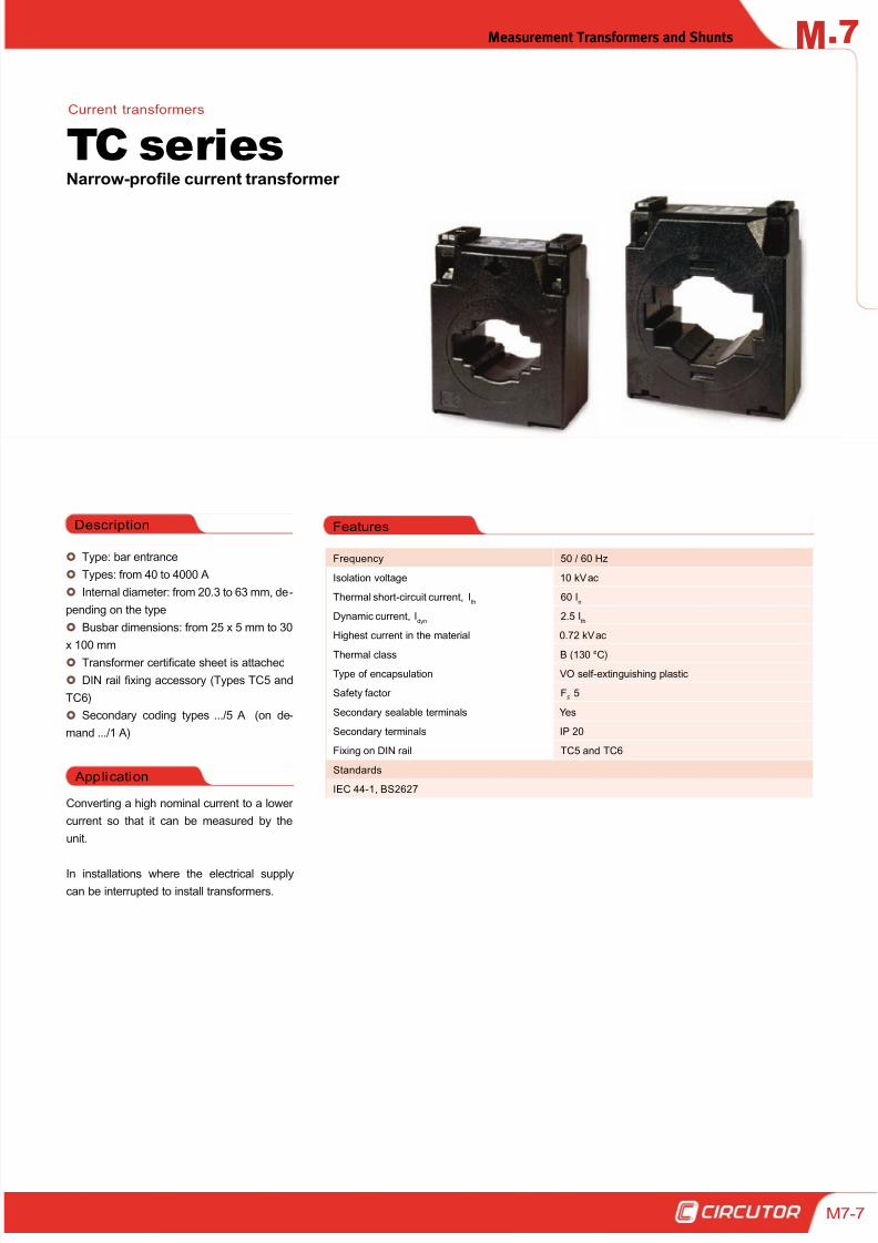
Product selection table
Measurement Wound primary Bar entrance Split core With converter Page
T C 40 . .. 4 000 A ac 7
T C H
100 ... 4 000 A ac 10
T A 750 ... 5 000 A ac 12
T P 100 ... 5 000 A ac 14
T A 2 1 0
5 ... 400 A ac 17
T M 4 5
5 ... 50 A ac 18
T W 2
5
100 .. . 300 A ac 19
T C 0 2 0
50 ... 1 500 A ac 0...20 mA 20
T C 4 2 0
5 ... 1 500 A ac 4...20 mA 20
T P 4 2 0
5 ... 4 000 A ac 4...20 mA 22
T I 4 2 0
2.5 ... 1 500 A ac 4...20 mA 24
T C B 4 2 0
2.5 ... 1 500 A ac 4...20 mA 25
T C M 4 2 0
2.5 ... 300 A ac 4...20 mA 26
S H U N T S
1 .. . 15 000 A dc 27
SELECTING A MEASUREMENT TRANSFORMER
8/12/2019 02 - Current TFs, Voltage TFs & Shunts
http://slidepdf.com/reader/full/02-current-tfs-voltage-tfs-shunts 7/32
Measurement Transformers and Shunts .7M
M7-7
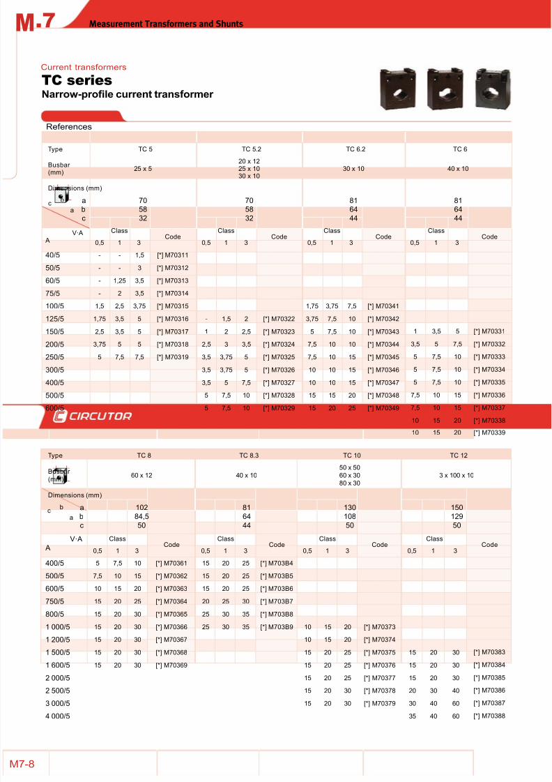
Type: bar entrance
Types: from 40 to 4000 A
Internal diameter: from 20.3 to 63 mm, de-
pending on the type
Busbar dimensions: from 25 x 5 mm to 30
x 100 mm
Transformer certificate sheet is attached
DIN rail fixing accessory (Types TC5 and
TC6)
Secondary coding types .../5 A (on de-
mand .../1 A)
Application
Converting a high nominal current to a lower
current so that it can be measured by the
unit.
In installations where the electrical supply
can be interrupted to install transformers.
FeaturesDescription
Narrow-profile current transformer
TC seriesCurrent transformers
Frequency 50 / 60 Hz
Isolation voltage 10 kV ac
Thermal short-circuit current, Ith
60 In
Dynamic current, Idyn
2.5 Ith
Highest current in the material 0.72 kV ac
Thermal class B (130 ºC)
Type of encapsulation VO self-extinguishing plastic
Safety factor FS 5
Secondary sealable terminals Yes
Secondary terminals IP 20
Fixing on DIN rail TC5 and TC6
Standards
IEC 44-1, BS2627
8/12/2019 02 - Current TFs, Voltage TFs & Shunts
http://slidepdf.com/reader/full/02-current-tfs-voltage-tfs-shunts 8/32
.7 Measurement Transformers and ShuntsM
7-8
References
Narrow-profile current transformer
TC seriesCurrent transformers
Type TC 5 TC 5.2 TC 6.2 TC 6
Busbar (mm)
25 x 520 x 1225 x 1030 x 10
30 x 10 40 x 10
Dimensions (mm)
ab
c
7058
32
7058
32
81
64
44
81
64
44
V·A A
ClassCode
ClassCode
ClassCode
ClassCode
0,5 1 3 0,5 1 3 0,5 1 3 0,5 1 3
40/5 - - 1,5 [*] M70311
50/5 - - 3 [*] M70312
60/5 - 1,25 3,5 [*] M70313
75/5 - 2 3,5 [*] M70314
100/5 1,5 2,5 3,75 [*] M70315 1,75 3,75 7,5 [*] M70341
125/5 1,75 3,5 5 [*] M70316 - 1,5 2 [*] M70322 3,75 7,5 10 [*] M70342
150/5 2,5 3,5 5 [*] M70317 1 2 2,5 [*] M70323 5 7,5 10 [*] M70343 1 3,5 5 [*] M70331
200/5 3,75 5 5 [*] M70318 2,5 3 3,5 [*] M70324 7,5 10 10 [*] M70344 3,5 5 7,5 [*] M70332
250/5 5 7,5 7,5 [*] M70319 3,5 3,75 5 [*] M70325 7,5 10 15 [*] M70345 5 7,5 10 [*] M70333
300/5 3,5 3,75 5 [*] M70326 10 10 15 [*] M70346 5 7,5 10 [*] M70334
400/5 3,5 5 7,5 [*] M70327 10 10 15 [*] M70347 5 7,5 10 [*] M70335
500/5 5 7,5 10 [*] M70328 15 15 20 [*] M70348 7,5 10 15 [*] M70336
600/5 5 7,5 10 [*] M70329 15 20 25 [*] M70349 7,5 10 15 [*] M7033710 15 20 [*] M70338
10 15 20 [*] M70339
Type TC 8 TC 8.3 TC 10 TC 12
Busbar
(mm)60 x 12 40 x 10
50 x 50
60 x 30
80 x 30
3 x 100 x 10
Dimensions (mm)
a
b
c
102
84,5
50
81
64
44
130
108
50
150
129
50
V·A
A
Class
Code
Class
Code
Class
Code
Class
Code0,5 1 3 0,5 1 3 0,5 1 3 0,5 1 3
400/5 5 7,5 10 [*] M70361 15 20 25 [*] M703B4
500/5 7,5 10 15 [*] M70362 15 20 25 [*] M703B5
600/5 10 15 20 [*] M70363 15 20 25 [*] M703B6
750/5 15 20 25 [*] M70364 20 25 30 [*] M703B7
800/5 15 20 30 [*] M70365 25 30 35 [*] M703B8
1 000/5 15 20 30 [*] M70366 25 30 35 [*] M703B9 10 15 20 [*] M70373
1 200/5 15 20 30 [*] M70367 10 15 20 [*] M70374
1 500/5 15 20 30 [*] M70368 15 20 25 [*] M70375 15 20 30 [*] M70383
1 600/5 15 20 30 [*] M70369 15 20 25 [*] M70376 15 20 30 [*] M70384
2 000/5 15 20 25 [*] M70377 15 20 30 [*] M70385
2 500/5 15 20 30 [*] M70378 20 30 40 [*] M70386
3 000/5 15 20 30 [*] M70379 30 40 60 [*] M70387
4 000/5 35 40 60 [*] M70388
b
ac
b
ac
8/12/2019 02 - Current TFs, Voltage TFs & Shunts
http://slidepdf.com/reader/full/02-current-tfs-voltage-tfs-shunts 9/32
Measurement Transformers and Shunts .7M
M7-9
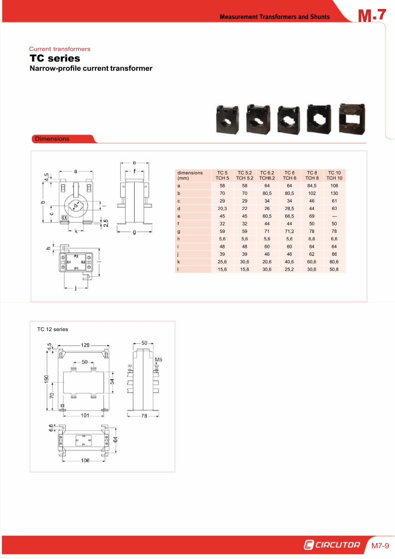
Dimensions
dimensions(mm)
TC 5TCH 5
TC 5.2TCH 5.2
TC 6.2TCH6.2
TC 6TCH 6
TC 8TCH 8
TC 10TCH 10
a 58 58 64 64 84,5 108
b 70 70 80,5 80,5 102 130
c 29 29 34 34 46 61
d 20,3 22 26 28,5 44 63
e 45 45 60,5 66,5 69 ---
f 32 32 44 44 50 50
g 59 59 71 71,2 78 78
h 5,6 5,6 5,6 5,6 6,6 6,6
i 48 48 60 60 64 64
j 39 39 46 46 62 86
k 25,6 30,6 20,6 40,6 60,6 80,6
l 15,6 15,6 30,6 25,2 30,6 50,8
TC 12 series
Narrow-profile current transformer
TC seriesCurrent transformers
8/12/2019 02 - Current TFs, Voltage TFs & Shunts
http://slidepdf.com/reader/full/02-current-tfs-voltage-tfs-shunts 10/32
.7 Measurement Transformers and ShuntsM
7-10
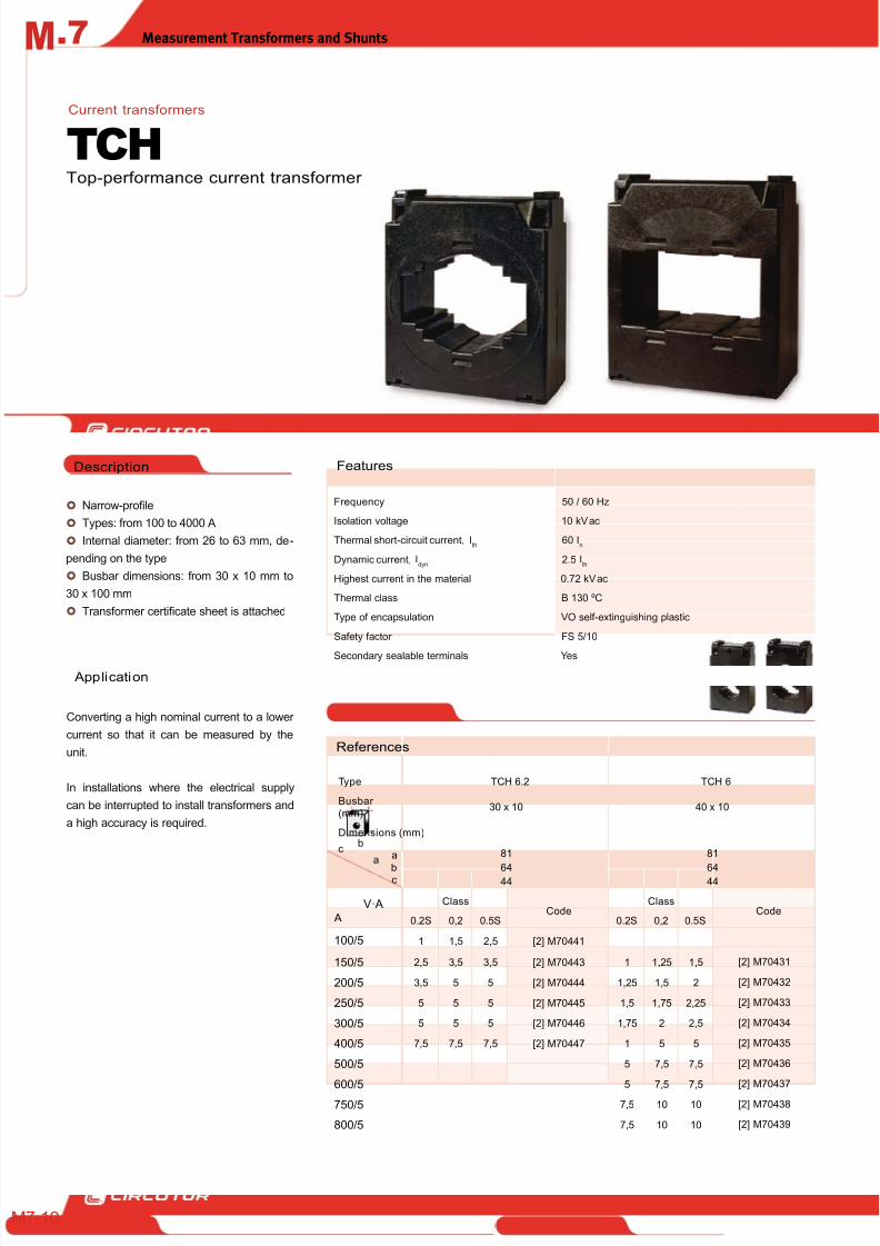
Narrow-profile
Types: from 100 to 4000 A
Internal diameter: from 26 to 63 mm, de-
pending on the type
Busbar dimensions: from 30 x 10 mm to
30 x 100 mm
Transformer certificate sheet is attached
Application
Converting a high nominal current to a lower
current so that it can be measured by the
unit.
In installations where the electrical supply
can be interrupted to install transformers and
a high accuracy is required.
FeaturesDescription
Top-performance current transformer
TCH
Frequency 50 / 60 Hz
Isolation voltage 10 kV ac
Thermal short-circuit current, Ith
60 In
Dynamic current, Idyn
2.5 Ith
Highest current in the material 0.72 kV ac
Thermal class B 130 ºC
Type of encapsulation VO self-extinguishing plastic
Safety factor FS 5/10
Secondary sealable terminals Yes
References
Current transformers
Type TCH 6.2 TCH 6
Busbar (mm)
30 x 10 40 x 10
Dimensions (mm)
a
bc
81
64
44
81
64
44
V·A
A
ClassCode
ClassCode
0.2S 0,2 0.5S 0.2S 0,2 0.5S
100/5 1 1,5 2,5 [2] M70441
150/5 2,5 3,5 3,5 [2] M70443 1 1,25 1,5 [2] M70431
200/5 3,5 5 5 [2] M70444 1,25 1,5 2 [2] M70432
250/5 5 5 5 [2] M70445 1,5 1,75 2,25 [2] M70433
300/5 5 5 5 [2] M70446 1,75 2 2,5 [2] M70434
400/5 7,5 7,5 7,5 [2] M70447 1 5 5 [2] M70435
500/5 5 7,5 7,5 [2] M70436
600/5 5 7,5 7,5 [2] M70437
750/5 7,5 10 10 [2] M70438
800/5 7,5 10 10 [2] M70439
b
ac
8/12/2019 02 - Current TFs, Voltage TFs & Shunts
http://slidepdf.com/reader/full/02-current-tfs-voltage-tfs-shunts 11/32
Measurement Transformers and Shunts .7M
M7-11
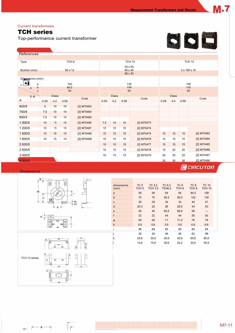
References
Top-performance current transformer
TCH seriesCurrent transformers
Type TCH 8 TCH 10 TCH 12
Busbar (mm) 60 x 12
50 x 50
60 x 30
80 x 30
3 x 100 x 10
Dimensions (mm)
a
b
c
102
84,5
50
130
108
50
150
129
50
V·A A
ClassCode
ClassCode
ClassCode
0.2S 0,2 0.5S 0.2S 0,2 0.5S 0.2S 0,2 0.5S
600/5 5 10 10 [2] M70463
750/5 7,5 10 10 [2] M70464
800/5 7,5 10 10 [2] M70465
1 000/5 10 15 15 [2] M70466 7,5 10 10 [2] M70473
1 200/5 10 15 15 [2] M70467 10 10 10 [2] M70474
1 500/5 10 15 15 [2] M70468 10 10 15 [2] M70475 10 15 15 [2] M70483
1 600/5 10 15 15 [2] M70469 10 10 15 [2] M70476 10 15 15 [2] M70484
2 000/5 10 10 15 [2] M70477 10 15 15 [2] M70485
2 500/5 10 10 15 [2] M70478 15 20 20 [2] M70486
3 000/5 10 10 15 [2] M70479 20 25 25 [2] M70487
4 000/5 25 30 30 [2] M70488
TCH 12 series
Dimensions
dimensions(mm)
TC 5TCH 5
TC 5.2TCH 5.2
TC 6.2TCH6.2
TC 6TCH 6
TC 8TCH 8
TC 10TCH 10
a 58 58 64 64 84,5 108
b 70 70 80,5 80,5 102 130
c 29 29 34 34 46 61
d 20,3 22 26 28,5 44 63
e 45 45 60,5 66,5 69 ---
f 32 32 44 44 50 50
g 59 59 71 71,2 78 78
h 5,6 5,6 5,6 5,6 6,6 6,6
i 48 48 60 60 64 64
j 39 39 46 46 62 86
k 25,6 30,6 20,6 40,6 60,6 80,6
l 15,6 15,6 30,6 25,2 30,6 50,8
b
ac
8/12/2019 02 - Current TFs, Voltage TFs & Shunts
http://slidepdf.com/reader/full/02-current-tfs-voltage-tfs-shunts 12/32
.7 Measurement Transformers and ShuntsM
7-12
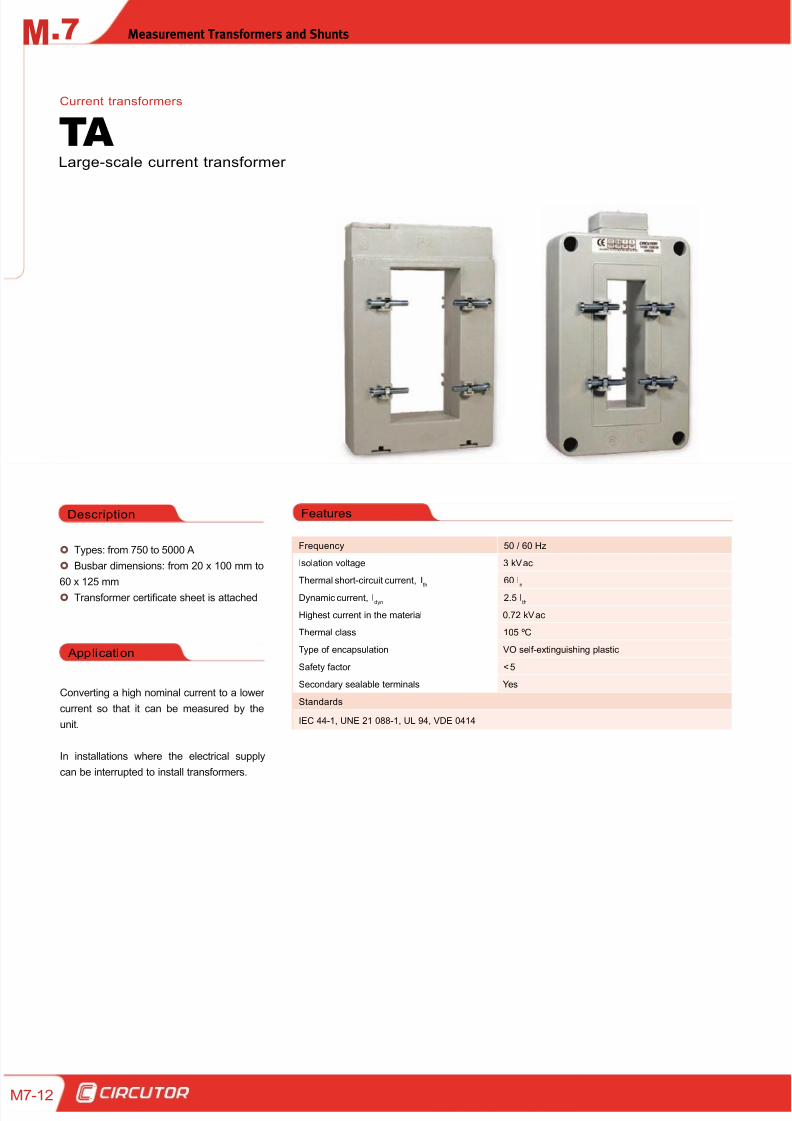
Types: from 750 to 5000 A
Busbar dimensions: from 20 x 100 mm to
60 x 125 mm
Transformer certificate sheet is attached
Application
Converting a high nominal current to a lower
current so that it can be measured by the
unit.
In installations where the electrical supply
can be interrupted to install transformers.
FeaturesDescription
Large-scale current transformer
TA
Frequency 50 / 60 Hz
Isolation voltage 3 kV ac
Thermal short-circuit current, Ith
60 In
Dynamic current, Idyn
2.5 Ith
Highest current in the material 0.72 kV ac
Thermal class 105 ºC
Type of encapsulation VO self-extinguishing plastic
Safety factor < 5
Secondary sealable terminals Yes
Standards
IEC 44-1, UNE 21 088-1, UL 94, VDE 0414
Current transformers
8/12/2019 02 - Current TFs, Voltage TFs & Shunts
http://slidepdf.com/reader/full/02-current-tfs-voltage-tfs-shunts 13/32
Measurement Transformers and Shunts .7M
M7-13
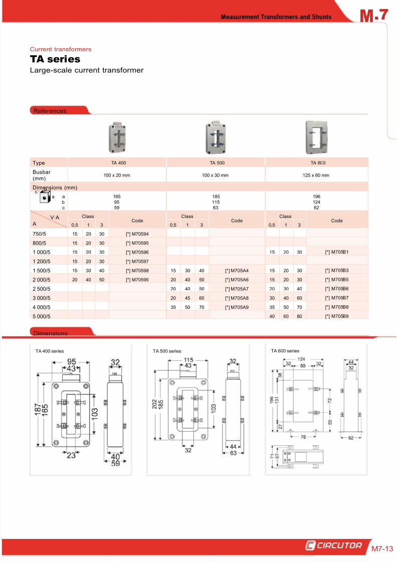
Large-scale current transformer
TA series
References
Current transformers
Type TA 400 TA 500 TA 600
Busbar (mm)
100 x 20 mm 100 x 30 mm 125 x 60 mm
Dimensions (mm)
abc
1659559
18511563
19612462
V·A
A
ClassCode
ClassCode
ClassCode
0,5 1 3 0,5 1 3 0,5 1 3
750/5 15 20 30 [*] M70594
800/5 15 20 30 [*] M70595
1 000/5 15 20 30 [*] M70596 15 20 30 [*] M705B1
1 200/5 15 20 30 [*] M70597
1 500/5 15 30 40 [*] M70598 15 30 40 [*] M705A4 15 20 30 [*] M705B3
2 000/5 20 40 50 [*] M70599 20 40 50 [*] M705A6 15 20 30 [*] M705B5
2 500/5 20 40 50 [*] M705A7 20 30 40 [*] M705B6
3 000/5 20 45 60 [*] M705A8 30 40 60 [*] M705B7
4 000/5 35 50 70 [*] M705A9 35 50 70 [*] M705B8
5 000/5 40 60 80 [*] M705B9
TA 400 series
Dimensions
TA 500 series TA 600 series
b
a
c
8/12/2019 02 - Current TFs, Voltage TFs & Shunts
http://slidepdf.com/reader/full/02-current-tfs-voltage-tfs-shunts 14/32
.7 Measurement Transformers and ShuntsM
7-14
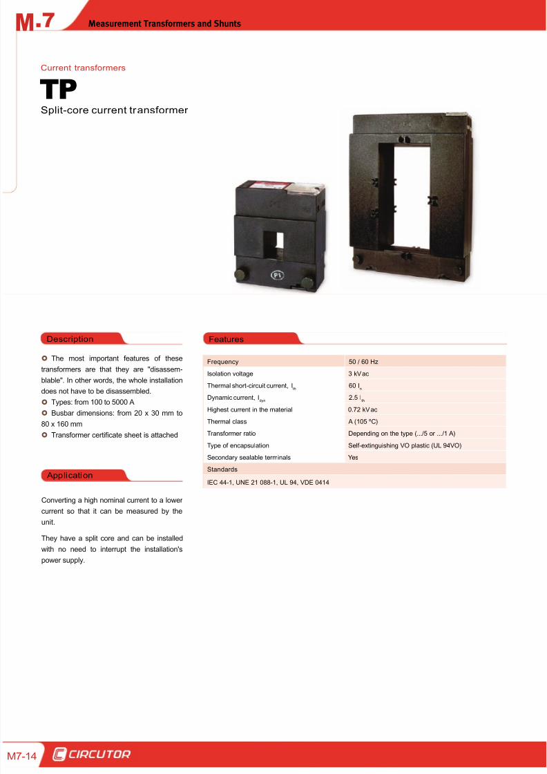
The most important features of these
transformers are that they are "disassem-
blable". In other words, the whole installation
does not have to be disassembled.
Types: from 100 to 5000 A
Busbar dimensions: from 20 x 30 mm to
80 x 160 mm
Transformer certificate sheet is attached
Application
Converting a high nominal current to a lower
current so that it can be measured by the
unit.
They have a split core and can be installed
with no need to interrupt the installation's
power supply.
FeaturesDescription
Split-core current transformer
TPCurrent transformers
Frequency 50 / 60 Hz
Isolation voltage 3 kV ac
Thermal short-circuit current, Ith
60 In
Dynamic current, Idyn
2.5 Ith
Highest current in the material 0.72 kV ac
Thermal class A (105 ºC)
Transformer ratio Depending on the type (.../5 or .../1 A)
Type of encapsulation Self-extinguishing VO plastic (UL 94VO)
Secondary sealable terminals Yes
Standards
IEC 44-1, UNE 21 088-1, UL 94, VDE 0414
8/12/2019 02 - Current TFs, Voltage TFs & Shunts
http://slidepdf.com/reader/full/02-current-tfs-voltage-tfs-shunts 15/32
Measurement Transformers and Shunts .7M
M7-15
References
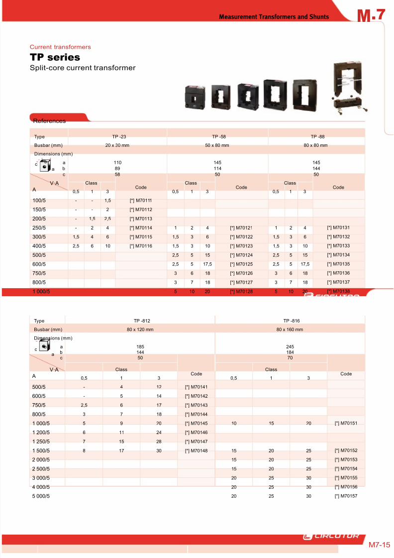
Type TP -812 TP -816
Busbar (mm) 80 x 120 mm 80 x 160 mm
Dimensions (mm)
a
bc
185
14450
245
18470
V·A
A
ClassCode
ClassCode
0,5 1 3 0,5 1 3
500/5 - 4 12 [*] M70141
600/5 - 5 14 [*] M70142
750/5 2,5 6 17 [*] M70143
800/5 3 7 18 [*] M70144
1 000/5 5 9 20 [*] M70145 10 15 20 [*] M70151
1 200/5 6 11 24 [*] M70146
1 250/5 7 15 28 [*] M70147
1 500/5 8 17 30 [*] M70148 15 20 25 [*] M70152
2 000/5 15 20 25 [*] M70153
2 500/5 15 20 25 [*] M70154
3 000/5 20 25 30 [*] M70155
4 000/5 20 25 30 [*] M701565 000/5 20 25 30 [*] M70157
Type TP -23 TP -58 TP -88
Busbar (mm) 20 x 30 mm 50 x 80 mm 80 x 80 mm
Dimensions (mm)
a
b
c
110
89
58
145
114
50
145
144
50
V·A
A
ClassCode
ClassCode
ClassCode
0,5 1 3 0,5 1 3 0,5 1 3
100/5 - - 1,5 [*] M70111
150/5 - - 2 [*] M70112
200/5 - 1,5 2,5 [*] M70113
250/5 - 2 4 [*] M70114 1 2 4 [*] M70121 1 2 4 [*] M70131
300/5 1,5 4 6 [*] M70115 1,5 3 6 [*] M70122 1,5 3 6 [*] M70132
400/5 2,5 6 10 [*] M70116 1,5 3 10 [*] M70123 1,5 3 10 [*] M70133
500/5 2,5 5 15 [*] M70124 2,5 5 15 [*] M70134
600/5 2,5 5 17,5 [*] M70125 2,5 5 17,5 [*] M70135
750/5 3 6 18 [*] M70126 3 6 18 [*] M70136
800/5 3 7 18 [*] M70127 3 7 18 [*] M70137
1 000/5 5 10 20 [*] M70128 5 10 20 [*] M70138
Split-core current transformer
TP seriesCurrent transformers
b
ac
b
ac
8/12/2019 02 - Current TFs, Voltage TFs & Shunts
http://slidepdf.com/reader/full/02-current-tfs-voltage-tfs-shunts 16/32
.7 Measurement Transformers and ShuntsM
7-16
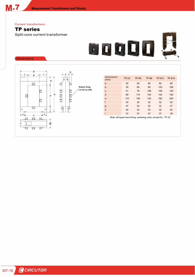
Dimensions
dimensions(mm)
TP-23 TP-58 TP-88 TP-812 TP-816
a 20 50 80 80 80
b 30 80 80 120 160
c 51 78 108 108 120
d 89 114 144 144 184
e 110 145 145 185 245
f 34 32 32 32 52
g 47 32 32 32 47
h 40 32 32 32 52
i 32 32 32 32 38
Note: All types have fixing centering units, except for TP-23
Split-core current transformer
TP seriesCurrent transformers
8/12/2019 02 - Current TFs, Voltage TFs & Shunts
http://slidepdf.com/reader/full/02-current-tfs-voltage-tfs-shunts 17/32
Measurement Transformers and Shunts .7M
M7-17
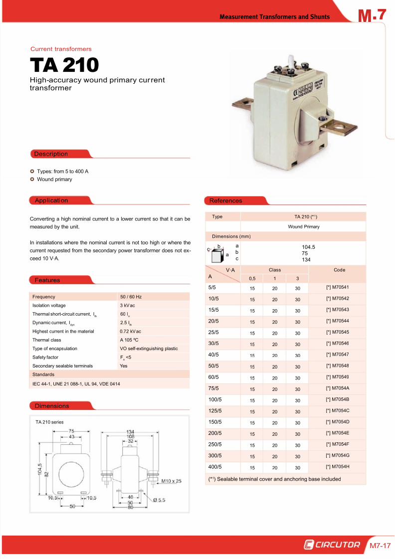
Types: from 5 to 400 A
Wound primary
Application
Converting a high nominal current to a lower current so that it can be
measured by the unit.
In installations where the nominal current is not too high or where the
current requested from the secondary power transformer does not ex-
ceed 10 V·A.
Description
High-accuracy wound primary currenttransformer
TA 210
Frequency 50 / 60 Hz
Isolation voltage 3 kV ac
Thermal short-circuit current, Ith
60 In
Dynamic current, Idyn
2.5 Ith
Highest current in the material 0.72 kV ac
Thermal class A 105 ºC
Type of encapsulation VO self-extinguishing plastic
Safety factor Fs <5
Secondary sealable terminals Yes
Standards
IEC 44-1, UNE 21 088-1, UL 94, VDE 0414
TA 210 series
Current transformers
Type TA 210 (*1)
Wound Primary
Dimensions (mm)
a
b
c
104.575
134
V·A
A
Class Code
0,5 1 3
5/5 15 20 30 [*] M70541
10/5 15 20 30 [*] M70542
15/5 15 20 30 [*] M70543
20/5 15 20 30 [*] M70544
25/5 15 20 30 [*] M70545
30/5 15 20 30 [*] M70546
40/5 15 20 30 [*] M70547
50/5 15 20 30 [*] M70548
60/5 15 20 30 [*] M70549
75/515 20 30
[*] M7054A
100/5 15 20 30 [*] M7054B
125/5 15 20 30 [*] M7054C
150/5 15 20 30 [*] M7054D
200/5 15 20 30 [*] M7054E
250/5 15 20 30 [*] M7054F
300/5 15 20 30 [*] M7054G
400/5 15 20 30 [*] M7054H
(*1) Sealable terminal cover and anchoring base included
Dimensions
Features
References
b
ac
8/12/2019 02 - Current TFs, Voltage TFs & Shunts
http://slidepdf.com/reader/full/02-current-tfs-voltage-tfs-shunts 18/32
.7 Measurement Transformers and ShuntsM
7-18
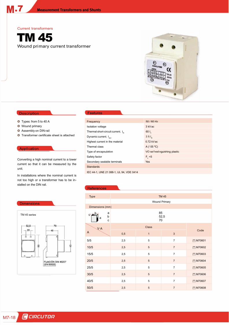
Types: from 5 to 40 A
Wound primary
Assembly on DIN rail
Transformer certificate sheet is attached
Application
Converting a high nominal current to a lower
current so that it can be measured by the
unit.
In installations where the nominal current is
not too high or a transformer has to be in-
stalled on the DIN rail.
Description
Wound primary current transformer
TM 45Current transformers
Frequency 50 / 60 Hz
Isolation voltage 3 kV ac
Thermal short-circuit current, Ith
60 In
Dynamic current, Idyn
2.5 Ith
Highest current in the material 0.72 kV ac
Thermal class A (105 ºC)
Type of encapsulation VO self-extinguishing plastic
Safety factor Fs <5
Secondary sealable terminals Yes
Standards
IEC 44-1, UNE 21 088-1, UL 94, VDE 0414
References
TM 45 series
Dimensions
Features
Type TM 45
Wound Primary
Dimensions (mm)
ab
c
8552,5
70
V·A A
ClassCode
0,5 1 3
5/5 2,5 5 7 [*] M70601
10/5 2,5 5 7 [*] M70602
15/5 2,5 5 7 [*] M70603
20/5 2,5 5 7 [*] M70604
25/5 2,5 5 7 [*] M70605
30/5 2,5 5 7 [*] M70606
40/5 2,5 5 7 [*] M70607
50/5 2,5 5 7 [*] M70608
b
ac
8/12/2019 02 - Current TFs, Voltage TFs & Shunts
http://slidepdf.com/reader/full/02-current-tfs-voltage-tfs-shunts 19/32
Measurement Transformers and Shunts .7M
M7-19
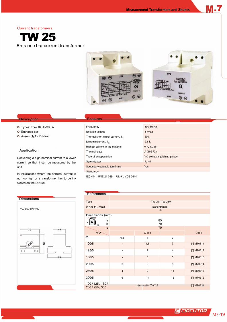
Types: from 100 to 300 A
Entrance bar
Assembly for DIN rail
Application
Converting a high nominal current to a lower
current so that it can be measured by the
unit.
In installations where the nominal current is
not too high or a transformer has to be in-
stalled on the DIN rail.
Description
Entrance bar current transformer
TW 25Current transformers
Frequency 50 / 60 Hz
Isolation voltage 3 kV ac
Thermal short-circuit current, Ith
60 In
Dynamic current, Idyn
2.5 Ith
Highest current in the material 0.72 kV ac
Thermal class A (105 ºC)
Type of encapsulation VO self-extinguishing plastic
Safety factor Fs <5
Secondary sealable terminals Yes
Standards
IEC 44-1, UNE 21 088-1, UL 94, VDE 0414
Dimensions
Features
Type TW 25 / TW 25M
inner Ø (mm) Bar entrance
25
Dimensions (mm)
ab
c
8570
70
V·A A
Class Code
0,5 1 3
100/5 - 1,5 3 [*] M70611
125/5 - 2 4 [*] M70612
150/5 - 3 5 [*] M70613
200/5 3 5 8 [*] M70614
250/5 4 9 11 [*] M70615
300/5 6 11 13 [*] M70616
100 / 125 / 150 /
200 / 250 / 300Identical to TW 25 [*] M70621
References
TW 25 / TW 25M
b
a
c
8/12/2019 02 - Current TFs, Voltage TFs & Shunts
http://slidepdf.com/reader/full/02-current-tfs-voltage-tfs-shunts 20/32
.7 Measurement Transformers and ShuntsM
7-20
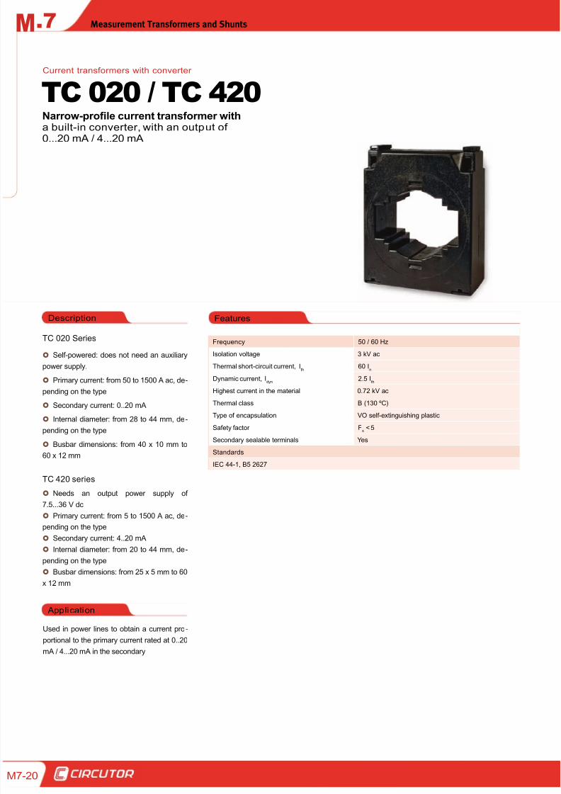
TC 020 Series
Self-powered: does not need an auxiliary
power supply.
Primary current: from 50 to 1500 A ac, de-
pending on the type
Secondary current: 0..20 mA
Internal diameter: from 28 to 44 mm, de-
pending on the type
Busbar dimensions: from 40 x 10 mm to
60 x 12 mm
TC 420 series
Needs an output power supply of
7.5...36 V dc
Primary current: from 5 to 1500 A ac, de-
pending on the type
Secondary current: 4..20 mA
Internal diameter: from 20 to 44 mm, de-
pending on the type
Busbar dimensions: from 25 x 5 mm to 60
x 12 mm
Application
Used in power lines to obtain a current pro -
portional to the primary current rated at 0..20
mA / 4...20 mA in the secondary
FeaturesDescription
Frequency 50 / 60 Hz
Isolation voltage 3 kV ac
Thermal short-circuit current, Ith
60 In
Dynamic current, Idyn
2.5 Ith
Highest current in the material 0.72 kV ac
Thermal class B (130 ºC)
Type of encapsulation VO self-extinguishing plasticSafety factor F
s < 5
Secondary sealable terminals Yes
Standards
IEC 44-1, B5 2627
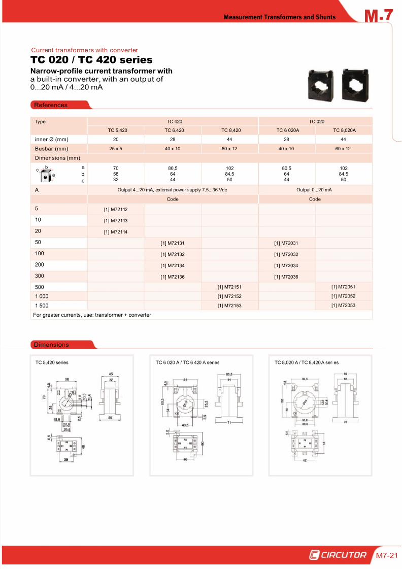
Narrow-profile current transformer witha built-in converter, with an output of
0...20 mA / 4...20 mA
TC 020 / TC 420Current transformers with converter
8/12/2019 02 - Current TFs, Voltage TFs & Shunts
http://slidepdf.com/reader/full/02-current-tfs-voltage-tfs-shunts 21/32
Measurement Transformers and Shunts .7M
M7-21
Narrow-profile current transformer witha built-in converter, with an output of0...20 mA / 4...20 mA
TC 020 / TC 420 seriesCurrent transformers with converter
References
TC 6 020 A / TC 6 420 A series
Dimensions
TC 8,020 A / TC 8,420 A seri es
Type TC 420 TC 020
TC 5,420 TC 6,420 TC 8,420 TC 6 020A TC 8,020A
inner Ø (mm) 20 28 44 28 44
Busbar (mm) 25 x 5 40 x 10 60 x 12 40 x 10 60 x 12
Dimensions (mm)
a
b
c
70
58
32
80,5
64
44
102
84,5
50
80,5
64
44
102
84,5
50
A Output 4...20 mA, external power supply 7.5...36 Vdc Output 0...20 mA
Code Code
5 [1] M72112
10 [1] M72113
20 [1] M72114
50 [1] M72131 [1] M72031
100 [1] M72132 [1] M72032
200 [1] M72134 [1] M72034
300 [1] M72136 [1] M72036
500 [1] M72151 [1] M72051
1 000[1] M72152 [1] M72052
1 500 [1] M72153 [1] M72053
For greater currents, use: transformer + converter
TC 5,420 series
b
ac
8/12/2019 02 - Current TFs, Voltage TFs & Shunts
http://slidepdf.com/reader/full/02-current-tfs-voltage-tfs-shunts 22/32
.7 Measurement Transformers and ShuntsM
7-22
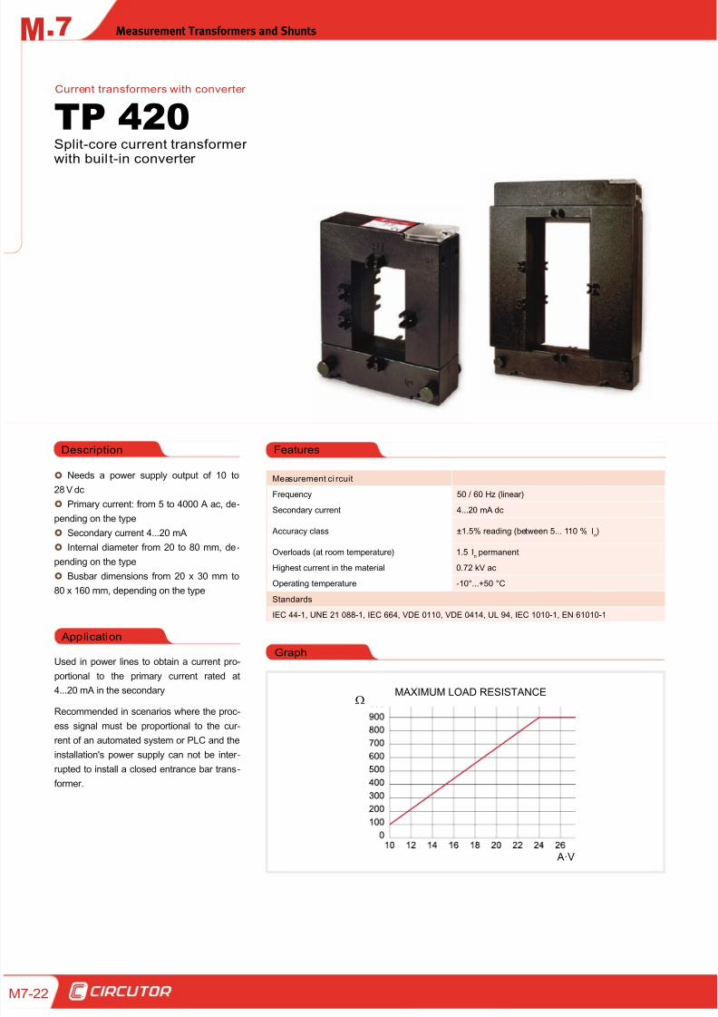
Features
Needs a power supply output of 10 to
28 V dc
Primary current: from 5 to 4000 A ac, de-
pending on the type
Secondary current 4...20 mA
Internal diameter from 20 to 80 mm, de-
pending on the type
Busbar dimensions from 20 x 30 mm to
80 x 160 mm, depending on the type
Application
Used in power lines to obtain a current pro-
portional to the primary current rated at
4...20 mA in the secondary
Recommended in scenarios where the proc-
ess signal must be proportional to the cur -
rent of an automated system or PLC and the
installation's power supply can not be inter -
rupted to install a closed entrance bar trans-
former.
Description
Measurement ci rcuit
Frequency 50 / 60 Hz (linear)
Secondary current 4...20 mA dc
Accuracy class ±1.5% reading (between 5... 110 %In)
Overloads (at room temperature) 1.5 In permanent
Highest current in the material 0.72 kV ac
Operating temperature -10°...+50 °C
Standards
IEC 44-1, UNE 21 088-1, IEC 664, VDE 0110, VDE 0414, UL 94, IEC 1010-1, EN 61010-1
Split-core current transformerwith buil t-in converter
TP 420Current transformers with converter
MAXIMUM LOAD RESISTANCE
A·V
Graph
8/12/2019 02 - Current TFs, Voltage TFs & Shunts
http://slidepdf.com/reader/full/02-current-tfs-voltage-tfs-shunts 23/32
Measurement Transformers and Shunts .7M
M7-23
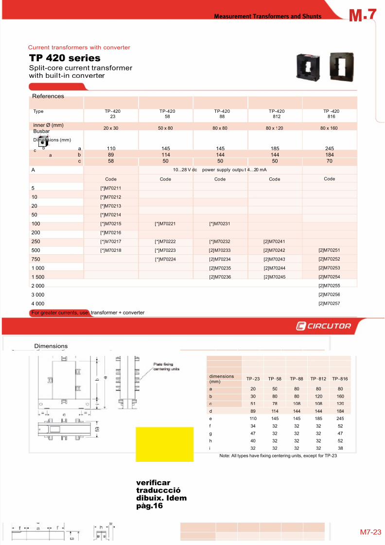
Type TP-42023
TP-42058
TP-42088
TP-420812
TP -420816
inner Ø (mm)Busbar
20 x 30 50 x 80 80 x 80 80 x 120 80 x 160
Dimensions (mm)
a
b
c
110
89
58
145
114
50
145
144
50
185
144
50
245
184
70
A 10...28 V dc power supply outpu t 4...20 mA
Code Code Code Code Code
5 [*]M70211
10 [*]M70212
20 [*]M70213
50 [*]M70214
100 [*]M70215 [*]M70221 [*]M70231
200 [*]M70216
250 [*]M70217 [*]M70222 [*]M70232 [2]M70241
500 [*]M70218 [*]M70223 [2]M70233 [2]M70242 [2]M70251
750 [*]M70224 [2]M70234 [2]M70243 [2]M70252
1 000 [2]M70235 [2]M70244 [2]M70253
1 500 [2]M70236 [2]M70245 [2]M70254
2 000 [2]M70255
3 000 [2]M70256
4 000 [2]M70257
For greater currents, use: transformer + converter
References
Dimensions
Split-core current transformerwith buil t-in converter
TP 420 series
Current transformers with converter
dimensions
(mm)TP-23 TP-58 TP-88 TP-812 TP-816
a 20 50 80 80 80
b 30 80 80 120 160
c 51 78 108 108 120
d 89 114 144 144 184
e 110 145 145 185 245
f 34 32 32 32 52
g 47 32 32 32 47
h 40 32 32 32 52
i 32 32 32 32 38
Note: All types have fixing centering units, except for TP-23
b
ac
verificar
traduccció
dibuix. Idem
pàg.16
8/12/2019 02 - Current TFs, Voltage TFs & Shunts
http://slidepdf.com/reader/full/02-current-tfs-voltage-tfs-shunts 24/32
.7 Measurement Transformers and ShuntsM
7-24
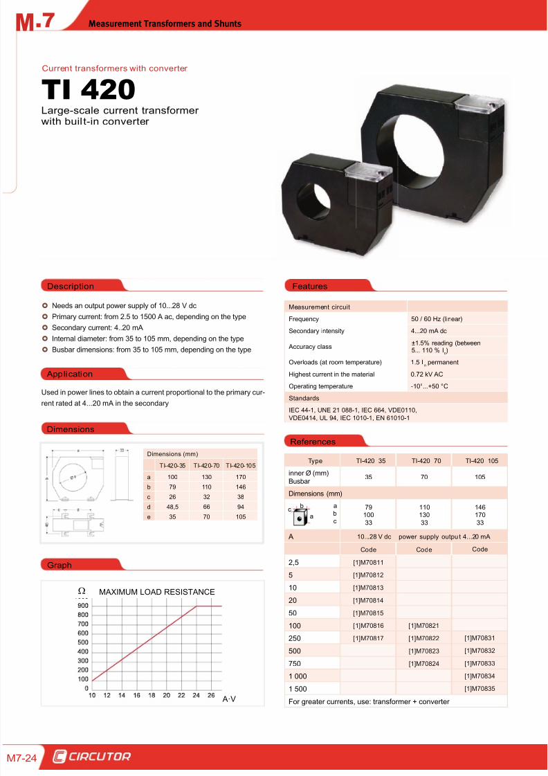
Needs an output power supply of 10...28 V dc
Primary current: from 2.5 to 1500 A ac, depending on the type
Secondary current: 4..20 mA
Internal diameter: from 35 to 105 mm, depending on the type
Busbar dimensions: from 35 to 105 mm, depending on the type
Application
Used in power lines to obtain a current proportional to the primary cur -
rent rated at 4...20 mA in the secondary
Description
Measurement circuit
Frequency 50 / 60 Hz (linear)
Secondary intensity 4...20 mA dc
Accuracy class±1.5% reading (between5... 110 % I
n)
Overloads (at room temperature) 1.5 In permanent
Highest current in the material 0.72 kV AC
Operating temperature -10°...+50 °C
Standards
IEC 44-1, UNE 21 088-1, IEC 664, VDE0110,VDE0414, UL 94, IEC 1010-1, EN 61010-1
Large-scale current transformerwith buil t-in converter
TI 420Current transformers with converter
Type TI-420 35 TI-420 70 TI-420 105
inner Ø (mm)Busbar
35 70 105
Dimensions (mm)
a
bc
79100
33
110130
33
146170
33
A 10...28 V dc power supply outpu t 4...20 mA
Code Code Code
2,5 [1]M70811
5 [1]M70812
10 [1]M70813
20 [1]M70814
50 [1]M70815
100 [1]M70816 [1]M70821
250 [1]M70817 [1]M70822 [1]M70831
500 [1]M70823 [1]M70832
750 [1]M70824 [1]M70833
1 000[1]M70834
1 500 [1]M70835
For greater currents, use: transformer + converter
Features
References
Dimensions
Dimensions (mm)
TI-420-35 TI-420-70 TI-420-105
a 100 130 170
b 79 110 146
c 26 32 38
d 48,5 66 94
e 35 70 105
MAXIMUM LOAD RESISTANCE
A·V
Graph
b
ac
8/12/2019 02 - Current TFs, Voltage TFs & Shunts
http://slidepdf.com/reader/full/02-current-tfs-voltage-tfs-shunts 25/32
Measurement Transformers and Shunts .7M
M7-25
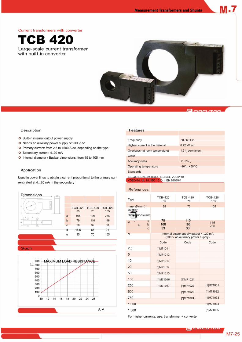
Built-in internal output power supply
Needs an auxiliary power supply of 230 V ac
Primary current: from 2.5 to 1500 A ac, depending on the type
Secondary current: 4..20 mA
Internal diameter / Busbar dimensions: from 35 to 105 mm
Application
Used in power lines to obtain a current proportional to the primary cur -
rent rated at 4...20 mA in the secondary
Description
Frequency 50 / 60 Hz
Highest current in the material 0.72 kV ac
Overloads (at room temperature) 1.5 In permanent
Class
Accuracy class ±1.5% In
Operating temperature -10°... +50 °C
Standards
IEC 44-1, UNE 21 088-1, IEC 664, VDE0110,
VDE0414, UL 94, IEC 1010-1, EN 61010-1
Large-scale current transformerwith buil t-in converter
TCB 420Current transformers with converter
Features
TypeTCB- 420
35
TCB -420
70
TCB- 420
105
inner Ø (mm)Busbar
35 70 105
Dimensions (mm)
a
bc
79166
33
110
19633
146236
A internal power suppl y output 4...20 mA
(230 V ac auxiliary power supply)
Code Code Code
2,5 [*]M71011
5 [*]M71012
10 [*]M71013
20 [*]M71014
50 [*]M71015
100 [*]M71016 [1]M71021
250 [*]M71017 [*]M71022 [1]M71031
500 [*]M71023 [*]M71032
750[*]M71024
[1]M71033
1 000 [1]M71034
1 500 [*]M71035
For higher currents, use: transformer + converter
References
TCB- 42035
TCB- 42070
TCB -420105
a 166 196 236
b 79 110 146
c 26 32 38
d 48,5 66 94
e 35 70 105
Dimensions
MAXIMUM LOAD RESISTANCE
A·V
Graph
b
ac
8/12/2019 02 - Current TFs, Voltage TFs & Shunts
http://slidepdf.com/reader/full/02-current-tfs-voltage-tfs-shunts 26/32
.7 Measurement Transformers and ShuntsM
7-26
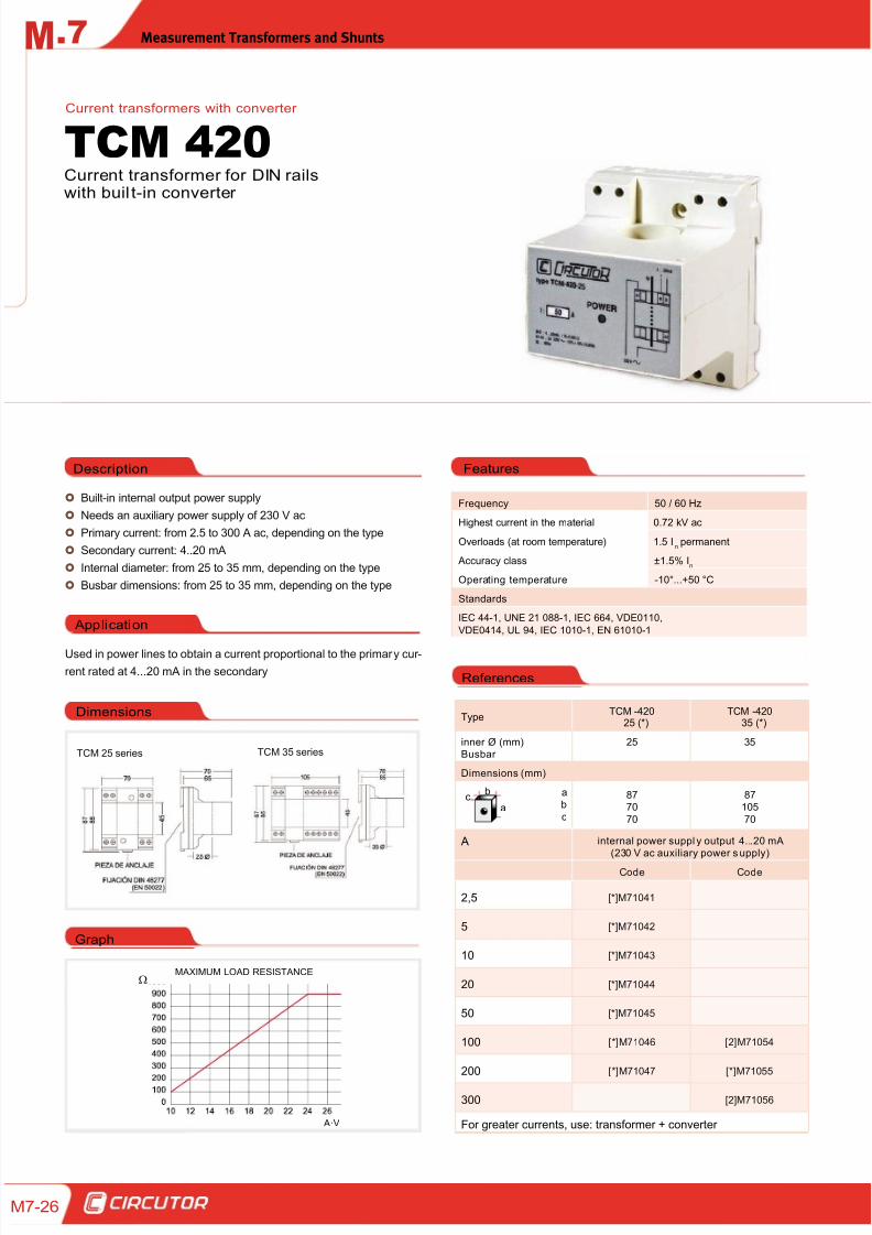
Built-in internal output power supply
Needs an auxiliary power supply of 230 V ac
Primary current: from 2.5 to 300 A ac, depending on the type
Secondary current: 4..20 mA
Internal diameter: from 25 to 35 mm, depending on the type
Busbar dimensions: from 25 to 35 mm, depending on the type
Application
Used in power lines to obtain a current proportional to the primary cur -
rent rated at 4...20 mA in the secondary
Description
Frequency 50 / 60 Hz
Highest current in the material 0.72 kV ac
Overloads (at room temperature) 1.5 In permanent
Accuracy class ±1.5% In
Operating temperature -10°...+50 °C
Standards
IEC 44-1, UNE 21 088-1, IEC 664, VDE0110,
VDE0414, UL 94, IEC 1010-1, EN 61010-1
Current transformer for DIN railswith buil t-in converter
TCM 420Current transformers with converter
TypeTCM -420
25 (*)TCM -420
35 (*)
inner Ø (mm)Busbar
25 35
Dimensions (mm)
ab
c
8770
70
87105
70
A internal power suppl y output 4...20 mA(230 V ac auxiliary power s upply)
Code Code
2,5 [*]M71041
5 [*]M71042
10 [*]M71043
20 [*]M71044
50 [*]M71045
100 [*]M71046 [2]M71054
200 [*]M71047 [*]M71055
300 [2]M71056
For greater currents, use: transformer + converter
Dimensions
Features
References
MAXIMUM LOAD RESISTANCE
A·V
TCM 25 series TCM 35 series
Graph
b
ac
8/12/2019 02 - Current TFs, Voltage TFs & Shunts
http://slidepdf.com/reader/full/02-current-tfs-voltage-tfs-shunts 27/32
Measurement Transformers and Shunts .7M
M7-27
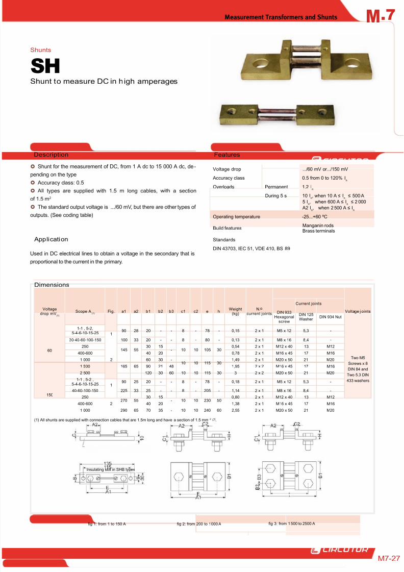
Voltage drop .../60 mV or.../150 mV
Accuracy class 0.5 from 0 to 120% In
Overloads Permanent 1.2 In
During 5 s 10 In, when 10 A ≤ I
n ≤ 500 A
5 In, when 600 A ≤ In ≤ 2 000 A2 I
n, when 2500 A ≤ I
n
Operating temperature -25...+60 ºC
Build featuresManganin rodsBrass terminals
Standards
DIN 43703, IEC 51, VDE 410, BS 89
Shunt for the measurement of DC, from 1 A dc to 15 000 A dc, de-
pending on the type
Accuracy class: 0.5
All types are supplied with 1.5 m long cables, with a section
of 1.5 m2
The standard output voltage is .../60 mV, but there are other types of
outputs. (See coding table)
Application
Used in DC electrical lines to obtain a voltage in the secondary that is
proportional to the current in the primary.
FeaturesDescription
Shunt to measure DC in high amperages
SH
Dimensions
Shunts
Voltagedrop mV
(1)
Scope A(1)
Fig. a1 a2 b1 b2 b3 c1 c2 e hWeight
(kg)N.o
current joints
Current joints
Voltage j ointsDIN 933Hexagonal
screw
DIN 125Washer
DIN 934 Nut
60
1-1 , 5-2,5-4-6-10-15-25 1
90 28 20 - - 8 - 78 - 0,15 2 x 1 M5 x 12 5,3 -
Two M5
Screws x 8
DIN 84 and
Two 5.3 DIN
433 washers
30-40-60-100-150 100 33 20 - - 8 - 80 - 0,13 2 x 1 M8 x 16 8,4 -
250
2
145 5530 15
- 10 10 105 300,54 2 x 1 M12 x 40 13 M12
400-600 40 20 0,78 2 x 1 M16 x 45 17 M16
1 000
165 65
60 30 -10 10 115 30
1,49 2 x 1 M20 x 50 21 M20
1 500 90 21 48 1,95 2 x 2 M16 x 45 17 M16
2 500 120 30 60 10 10 115 30 3 2 x 2 M20 x 50 21 M20
150
1-1 , 5-2 ,5-4-6-10-15-25 1
90 25 20 - - 8 - 78 - 0,18 2 x 1 M5 x 12 5,3 -
40-60-100-150 225 33 25 - - 8 - 205 - 1,14 2 x 1 M8 x 16 8,4 -
250
2 270 55
30 15
- 10 10 230 50
0,80 2 x 1 M12 x 40 13 M12
400-600 40 20 1,38 2 x 1 M16 x 45 17 M16
1 000 290 65 70 35 - 10 10 240 60 2,55 2 x 1 M20 x 50 21 M20
(1) All shunts are supplied with connection cables that are 1.5m long and have a section of 1.5 mm2 .
Insulating slot in SHB types
fig 1: from 1 to 150 A fig 2: from 200 to 1 000 A fig 3: from 1 500 to 2500 A
8/12/2019 02 - Current TFs, Voltage TFs & Shunts
http://slidepdf.com/reader/full/02-current-tfs-voltage-tfs-shunts 28/32
.7 Measurement Transformers and ShuntsM
7-28
References
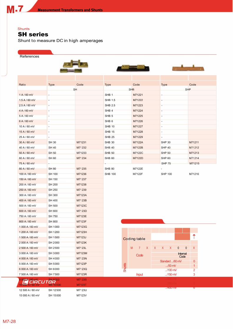
Shunt to measure DC in high amperages
SH seriesShunts
Ratio Type Code Type Code Type Code
SH SHB SHP
1 A / 60 mV - SHB 1 M71221 -
1.5 A / 60 mV - SHB 1.5 M71222 -
2.5 A / 60 mV - SHB 2.5 M71223 -
4 A / 60 mV - SHB 4 M71224 -
5 A / 60 mV - SHB 5 M71225 -
6 A / 60 mV - SHB 6 M71226 -
10 A / 60 mV - SHB 10 M71227 -
15 A / 60 mV - SHB 15 M71228 -
25 A / 60 mV - SHB 25 M71229 -
30 A / 60 mV SH 30 M71231 SHB 30 M7122A SHP 30 M71211
40 A / 60 mV SH 40 M71232 SHB 40 M7122B SHP 40 M71212
50 A / 60 mV SH 50 M71233 SHB 50 M7122C SHP 50 M71213
60 A / 60 mV SH 60 M71234 SHB 60 M7122D SHP 60 M71214
75 A / 60 mV - - SHP 75 M71215
80 A / 60 mV SH 80 M71235 SHB 80 M7122E -
100 A / 60 mV SH 100 M71236 SHB 100 M7122F SHP 100 M71216
150 A / 60 mV SH 150 M71237
200 A / 60 mV SH 200 M71238
250 A / 60 mV SH 250 M71239
300 A / 60 mV SH 300 M7123A
400 A / 60 mV SH 400 M7123B
500 A / 60 mV SH 500 M7123C
600 A / 60 mV SH 600 M7123D
750 A / 60 mV SH 750 M7123E
800 A / 60 mV SH 800 M7123F
1 000 A / 60 mV SH 1000 M7123G
1 200 A / 60 mV SH 1200 M7123H
1 500 A / 60 mV SH 1500 M7123J
2 000 A / 60 mV SH 2000 M7123K
2 500 A / 60 mV SH 2500 M7123L
3 000 A / 60 mV SH 3000 M7123M
4 000 A / 60 mV SH 4000 M7123N
5 000 A / 60 mV SH 5000 M7123P
6 000 A / 60 mV SH 6000 M7123Q
7 500 A / 60 mV SH 7500 M7123R
8 000 A / 60 mV SH 8000 M7123S
10 000 A / 60 mV SH 10000 M7123T
12 500 A / 60 mV SH 12500 M7123U
15 000 A / 60 mV SH 15000 M7123V
Coding table
S h u n t s
M 7 X X X X 0 0 X
CodeInternalCode
Input
Standard .../60 mV 0
.../50 mV 1
.../100 mV 2
.../150 mV 3
.../200 mV 4
.../300 mV 5
.../400 mV 6
8/12/2019 02 - Current TFs, Voltage TFs & Shunts
http://slidepdf.com/reader/full/02-current-tfs-voltage-tfs-shunts 29/32
Measurement Transformers and Shunts .7M
M7-29
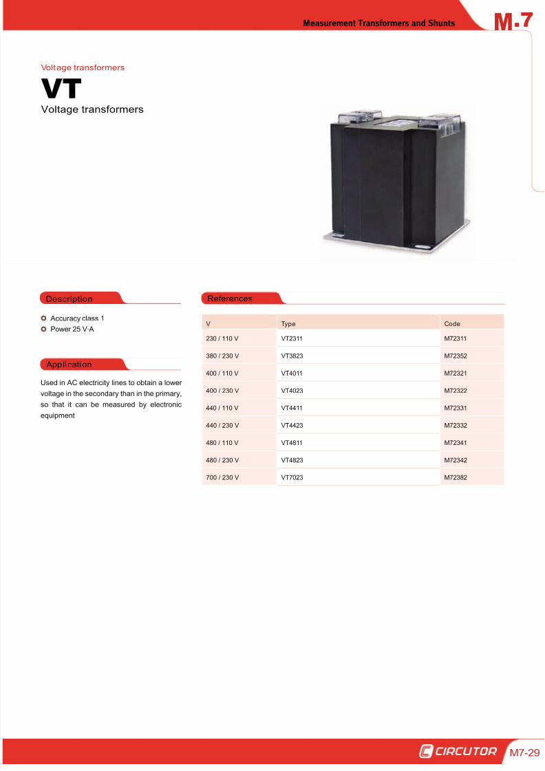
Accuracy class 1
Power 25 V·A
Application
Used in AC electricity lines to obtain a lower
voltage in the secondary than in the primary,
so that it can be measured by electronicequipment
Description
Voltage transformers
VTVoltage transformers
References
V Type Code
230 / 110 V VT2311 M72311
380 / 230 V VT3823 M72352
400 / 110 V VT4011 M72321
400 / 230 V VT4023 M72322
440 / 110 V VT4411 M72331
440 / 230 V VT4423 M72332
480 / 110 V VT4811 M72341
480 / 230 V VT4823 M72342
700 / 230 V VT7023 M72382
8/12/2019 02 - Current TFs, Voltage TFs & Shunts
http://slidepdf.com/reader/full/02-current-tfs-voltage-tfs-shunts 30/32
.7 Measurement Transformers and ShuntsM
7-30
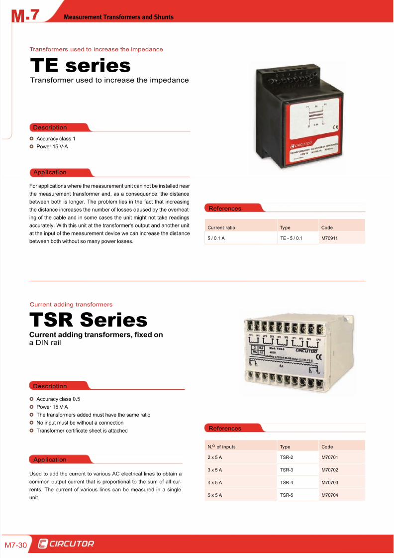
Accuracy class 1
Power 15 V·A
Application
For applications where the measurement unit can not be installed near
the measurement transformer and, as a consequence, the distancebetween both is longer. The problem lies in the fact that increasing
the distance increases the number of losses caused by the overheat-
ing of the cable and in some cases the unit might not take readings
accurately. With this unit at the transformer's output and another unit
at the input of the measurement device we can increase the distance
between both without so many power losses.
Description
Transformer used to increase the impedance
TE seriesTransformers used to increase the impedance
References
Current ratio Type Code
5 / 0.1 A TE - 5 / 0.1 M70911
Accuracy class 0.5
Power 15 V·A
The transformers added must have the same ratio
No input must be without a connection
Transformer certificate sheet is attached
Application
Used to add the current to various AC electrical lines to obtain a
common output current that is proportional to the sum of all cur -
rents. The current of various lines can be measured in a single
unit.
Description
Current adding transformers, fixed ona DIN rail
TSR SeriesCurrent adding transformers
References
N.o of inputs Type Code
2 x 5 A TSR-2 M70701
3 x 5 A TSR-3 M70702
4 x 5 A TSR-4 M70703
5 x 5 A TSR-5 M70704
8/12/2019 02 - Current TFs, Voltage TFs & Shunts
http://slidepdf.com/reader/full/02-current-tfs-voltage-tfs-shunts 31/32
Measurement Transformers and Shunts .7M
M7-31
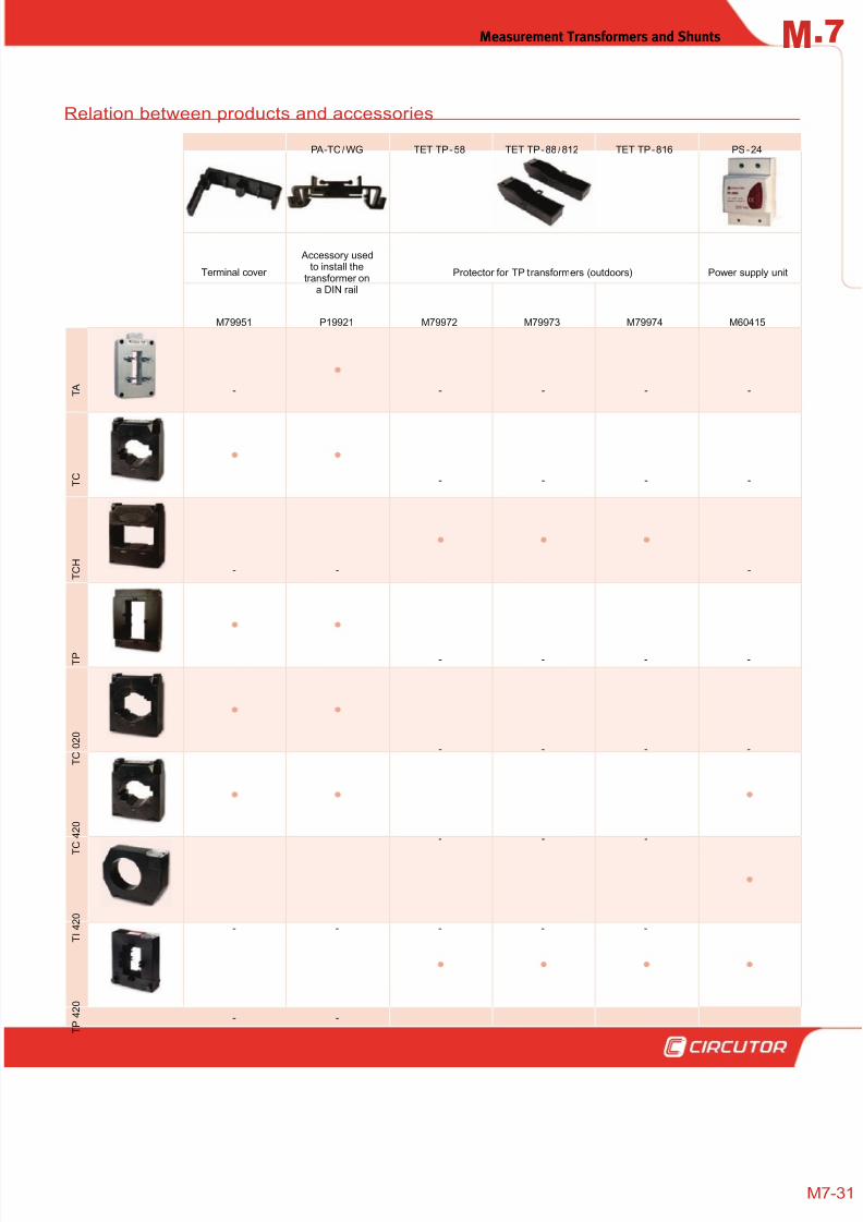
Relation between products and accessories
PA-TC/WG TET TP-58 TET TP-88 /812 TET TP-816 PS-24
Terminal cover
Accessory usedto install the
transformer ona DIN rail
Protector for TP transformers (outdoors) Power supply unit
M79951 P19921 M79972 M79973 M79974 M60415
T A - - - - -
T C - - - -
T C H
- - -
T P - - - -
T C 0 2 0
- - - -
T C 4 2 0
- - -
T I 4 2 0
- - - - -
T P 4 2 0
- -

8/12/2019 02 - Current TFs, Voltage TFs & Shunts
http://slidepdf.com/reader/full/02-current-tfs-voltage-tfs-shunts 32/32