Embed Size (px)
Citation preview

1
AUTOSAR
AUTomotive Open System ARchitecture
Contents
• Automotive Systems and SW Engineering
• Use Cases of AUTOSAR Results
• Main Concepts: Architecture
• Main Concepts: Methodology
• Main Concepts: Application Interfaces
2
1
2

2
Automotive Systems and SW Engineering
Automotive Open System Architecture
Cooperate on standards – compete on implementation
4
3
4
3
AUTOSAR Managing Complexity
5
Project Objectives and Main Working Topics
6
Architecture
ApplicationInterfaces Methodology
Implementation andstandardization of basic system functions as an OEM wide “Standard Core” solution
Scalability to different vehicle and platform variants
Transferability of functions throughout network
Integration of functional modules from multiple suppliers
Maintainabilitythroughout the whole “Product Life Cycle”
Increased use of “Commercial off the shelf hardware”
Software updatesand upgrades over vehicle lifetime
Redundancyactivation
Consideration of availability and safetyrequirements
5
6

4
Main Working Topics
7
Architecture
ApplicationInterfaces Methodology
Architecture:Software architecture including a complete basic or environmental software stack for ECUs – the so called AUTOSAR Basic Software – as an integration platform for hardware independent software applications.
Architecture
ApplicationInterfaces Methodology
Methodology:Exchange formats or description templates to enable a seamless configuration process of the basic software stack and the integration of application software in ECUs and it includes even the methodology how to use this framework.
Architecture
ApplicationInterfaces Methodology
Application Interfaces:Specification of interfaces of typical automotive applications from all domains in terms of syntax and semantics, which should serve as a standard for application software.
Technical Scope of AUTOSAR
8
Methodology
ExchangeFormats
Meta Model
InputTemplates
Virtual FunctionBus (VFB)
RunTimeEnvironment
ErrorHandling
ConfigurationConcept
MemoryServices
OS Kernel
ModeManagement
NetworkManagement
Comm.ServicesDiagnostics
GatewayBus systems
Drivers
ComplexDrivers
MCUAbstraction
ECUAbstraction
New concepts
Industry-wide consolidation of ‘existing’ basic software designs
7
8
5
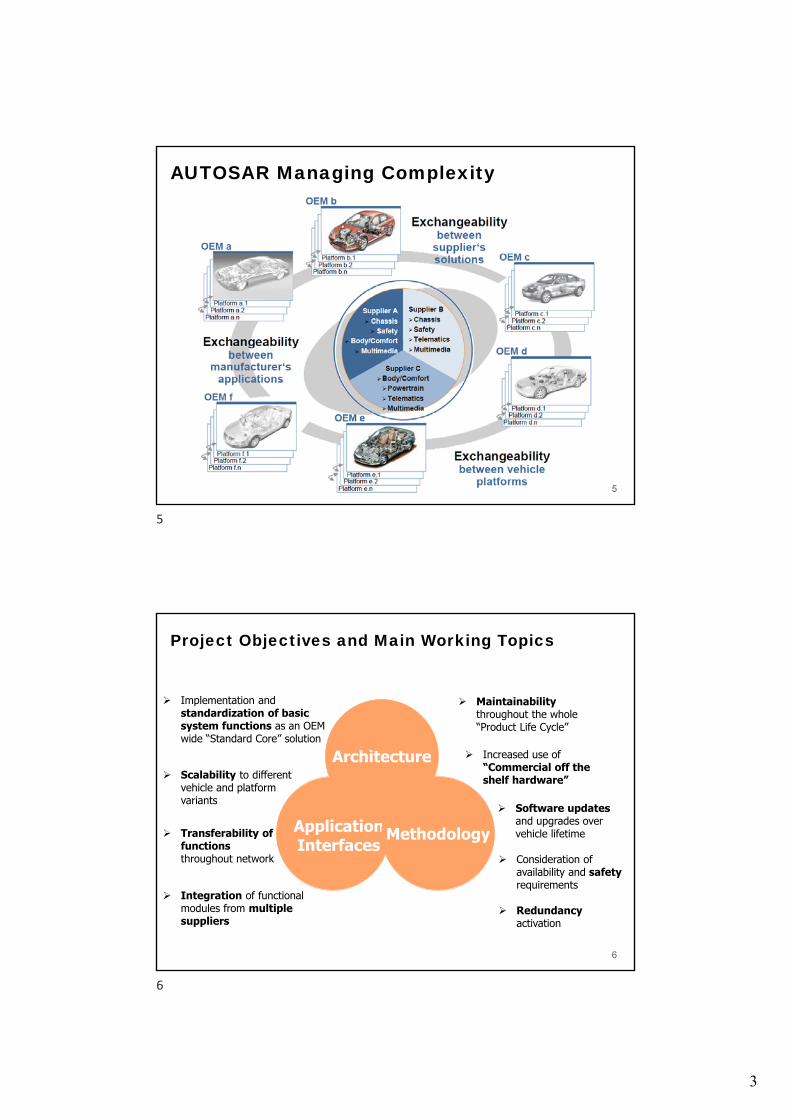
Benefits from AUTOSAR
9
OEM
OEM overlapping reuse of software modules Maintaining ability to compete on innovative functions,
enlarged design flexibility Simplification of the integration task Reduction of total SW development costs
Supplier Reduction of version proliferation Development partitioning among suppliers Increase of efficiency in functional development New business models possible
Tool Provider Common interfaces with development
processes Seamless, manageable, task optimized
(time dependent) tool landscape
New Marketentrant
Transparent and defined interfaces enable new business models
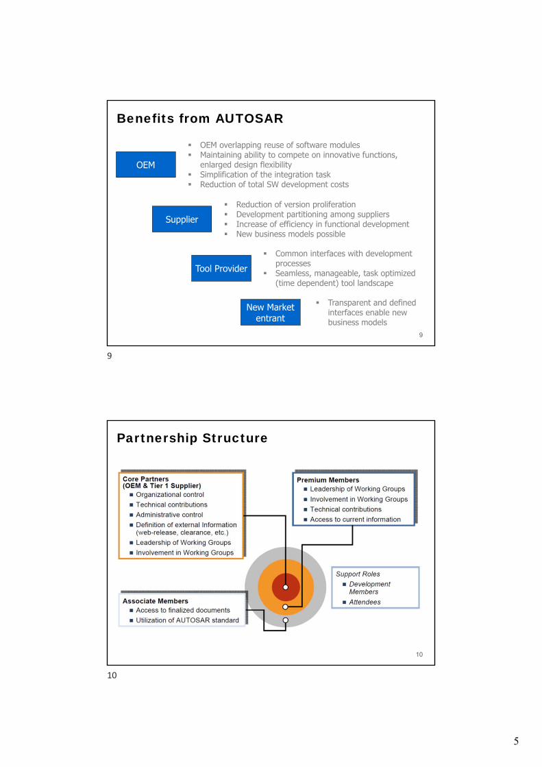
Partnership Structure
10
9
10

6
Core Partners and Members
11
Up-to-date status see: http://www.autosar.org
Top Level Schedule for AUTOSAR
12
11
12

7
AUTOSAR Phase II 2007 - 2009
• Exploitation and maintenance— Already in 2008 the first cars on the road with AUTOSAR technology
inside— All core partners have planned the introduction of AUTOSAR products
until 2010— Establish conformance test specifications and process
• Further development and amendment of the standard, e.g.— Functional safety features— Support for multi core microcontrollers— Vehicle & application mode management— Debugging and error handling— Variant handling— Timing model— Standardization of application interfaces
13
AUTOSAR Phase III 2010 - 2012
• Basic development of the standard• Selective enhancement of the standard based on a stable
architecture and methodology• Maintenance and improved maintainability of the different
releases used for series production and support of the exploitation into the market
14
13
14
8
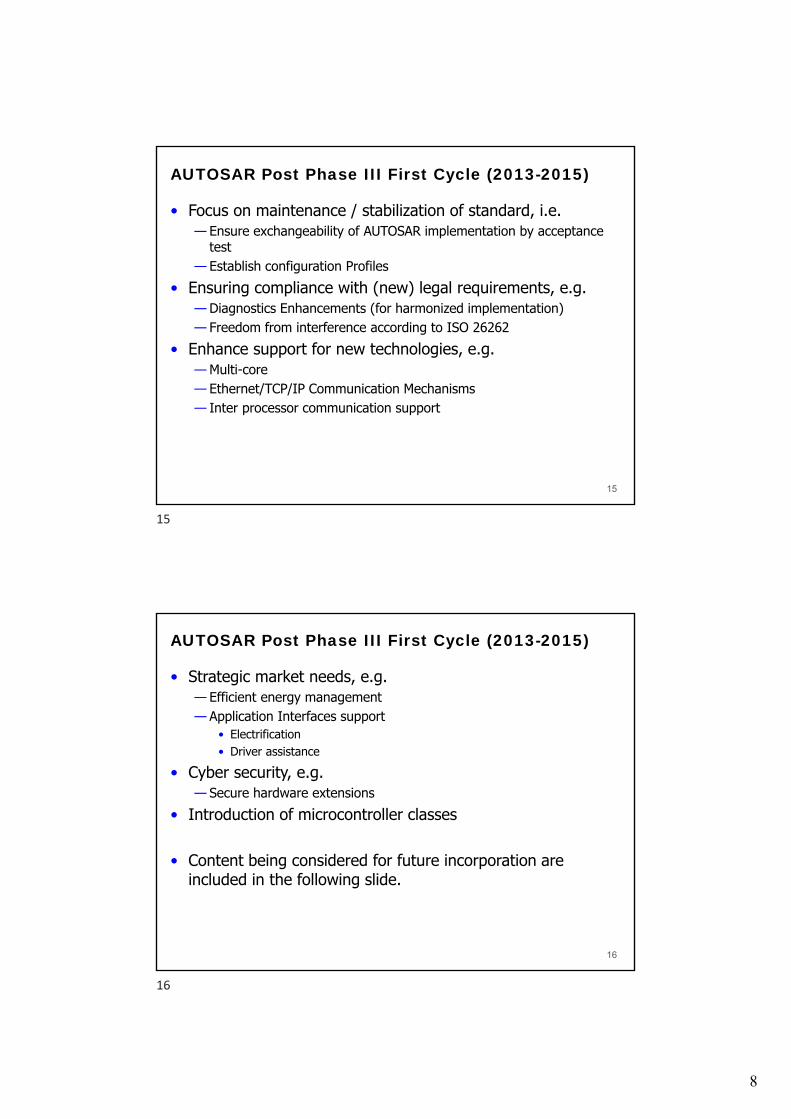
AUTOSAR Post Phase III First Cycle (2013-2015)
• Focus on maintenance / stabilization of standard, i.e.— Ensure exchangeability of AUTOSAR implementation by acceptance
test— Establish configuration Profiles
• Ensuring compliance with (new) legal requirements, e.g.— Diagnostics Enhancements (for harmonized implementation)— Freedom from interference according to ISO 26262
• Enhance support for new technologies, e.g.— Multi-core— Ethernet/TCP/IP Communication Mechanisms— Inter processor communication support
15
AUTOSAR Post Phase III First Cycle (2013-2015)
• Strategic market needs, e.g.— Efficient energy management— Application Interfaces support
• Electrification• Driver assistance
• Cyber security, e.g.— Secure hardware extensions
• Introduction of microcontroller classes
• Content being considered for future incorporation are included in the following slide.
16
15
16

9
Technical Content under discussion for 4.x
17
Work Package Breakdown Structure
18
17
18

10
Use Cases of AUTOSAR Results
Exchange of SW-Components Re-use of SW components for different
platforms
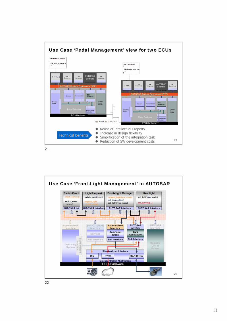
Use Case ‘Pedal Management’ view for one ECU
• Implementation of functions independent on distribution on different ECU as communication will be done via ECU-individual AUTOSAR-RTE exclusively
20
19
20
11
Use Case ‘Pedal Management’ view for two ECUs
21
Technical benefits Reuse of Intellectual Property Increase in design flexibility Simplification of the integration task Reduction of SW development costs
Use Case ‘Front-Light Management’ in AUTOSAR
22
21
22

12
Exchange of type of front-light
23
Distribution on ECUs
24
23
24
13
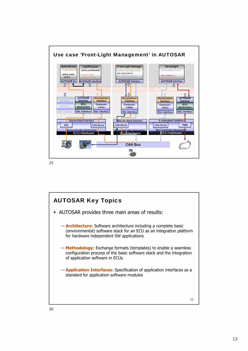
Use case ‘Front-Light Management’ in AUTOSAR
25
AUTOSAR Key Topics
• AUTOSAR provides three main areas of results:
— Architecture: Software architecture including a complete basic (environmental) software stack for an ECU as an integration platform for hardware independent SW applications
— Methodology: Exchange formats (templates) to enable a seamless configuration process of the basic software stack and the integration of application software in ECUs
— Application Interfaces: Specification of application interfaces as a standard for application software modules
26
25
26

14
Main Concepts: Architecture
Basic Software modules Run time environment and communication AUTOSAR Specification
Standardized AUTOSAR Interfaces
28
AUTOSAR• Standardized, openly
disclosed interfaces• HW independent SW layer• Transferability of functions• Redundancy activation
AUTOSAR RTEBy specifying interfaces and their communication mechanisms, the applications are decoupled from the underlying HW and Basic SW, enabling the realization of Standard Library Functions.
27
28

15
Standardized AUTOSAR Interfaces
29
AUTOSAR Basic Software
30
29
30
16
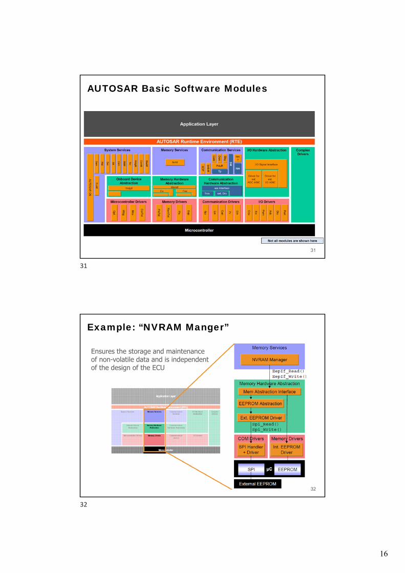
AUTOSAR Basic Software Modules
31
Example: “NVRAM Manger”
32
Ensures the storage and maintenance of non-volatile data and is independent of the design of the ECU
31
32
17
Example: “NVRAM Manger”
33
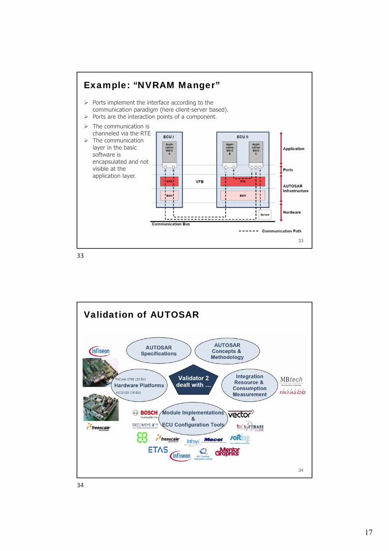
Ports implement the interface according to the communication paradigm (here client-server based).
Ports are the interaction points of a component. The communication is
channeled via the RTE The communication
layer in the basic software is encapsulated and not visible at the application layer.
Validation of AUTOSAR
34
33
34

18
Used AUTOSAR specifications
35
Validation of Standardized SW Specifications:Functionality & Scalability
36
The specified application provides ‘realistic’ functionality: Calculating of the vehicle speed based on several inputs Displaying the calculated speed
35
36

19
System Test Approach: Functionality & Scalability
37
Scalability is divided into 3 aspects: Distribution of the given application on several nodes. Using the appropriate communication bus technology Using the appropriate platform for each node.
Experience with AUTOSAR concepts and methodology: RTE
38
RTE concept was validated in the system test where a “dummy” real world application was created with a couple of AUTOSAR SW-C’s and IO Hardware Abstraction
RTE overhead = low !
Lessons learned:
Configuration of RTE might be very complex as long the requirements of the RTE and the OS are not optimized.
Close linkage of RTE & OS requires close cooperation between implementers
37
38
20
Experience with AUTOSAR concepts and methodology: IO Hardware Abstraction
39
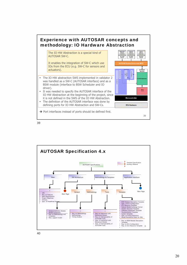
The IO HW Abstraction is a special kind of AUTOSAR SW-C.
It enables the integration of SW-C which use IOs from the ECU (e.g. SW-C for sensors and actuators).
The IO HW abstraction SWS implemented in validator 2 was handled as a SW-C (AUTOSAR interface) and as a BSW module (interface to BSW Scheduler and IO driver).
It was needed to specify the AUTOSAR interface of the IO HW Abstraction at the beginning of the project, since it is not defined in the SWS of the IO HW Abstraction.
The definition of the AUTOSAR interface was done by defining ports for IO HW Abstraction and SW-Cs.
Port interfaces instead of ports should be defined first.
AUTOSAR Specification 4.x
40
MainMain
AUTOSAR SpecificationsAUTOSAR Specifications
x
• VFB• Req. on Features• Main Requirements• Project Objectives• Glossary• Spec. of Predefined Names
SW ArchitectureSW Architecture Methodology & TemplatesMethodology & Templates Application InterfacesApplication Interfaces
Standard SpecificationAuxiliary Material
Next PageMethodology Tools Template
x
• Req. on Methodology• Methodology• Timing Analysis
x
• Req. on Interaction with Behavioral Models
• Req. on Interoperability of AUTOSAR Tools
• Spec. of Interaction with Behavioral Models
• Spec. of Interoperability of AUTOSAR Tools
• BSW Module Description Template• Spec. of ECU Configuration• ECU Resource Template• Feature Model Exchange Format• Generic Structure Template• Software Component Template• Standardization Template• System Template• Spec. of Timing Extensions• Model Persistence Rules for XML
• Req. on BSW Module Description Template
• Req. on ECU Configuration• Req. on ECU Resource Template• …
General
• General Definition Models• Model Constraints• Req. on Methodology and
Templates• Misc. support model
Next Page
39
40

21
AUTOSAR Specification 4.x
41
• Spec. of BSW Modules
• Spec. of Standard Types
• Explanation of Error Handling on App. Level
• Complex Driver Design & Integration Guideline
• Desc. Of Standard Errors• Exp. Interrupt Handling• Layered SW Architecture• Multi-Core Guide• Req. BSW Modules• BSW Module List• Modeling Guidelines of
BSW EA UML Model• Technical Safety
Concept Status Report
Standard SpecificationAuxiliary MaterialSW ArchitectureSW Architecture
GeneralCommunication
StackSystemServices
DiagnosticServices
Memory Stack
PeripheralsImplementation
IntegrationRTE
• Spec. of CAN Driver, CAN Interface, COM, Ethernet Driver …
• Req. on CAN, COM, Ethernet,FlexRay, Gateway, LIN, SAEJ11939, TTCAN, XCP
• Req. on IPDU Multiplexer• Req. on Network Management• Example of a Serialization
Protocol
• OS• WatchdogManager• ECU_StateManager• CRC_Routines• ModeManagement• BSW_Scheduler
….
• Req. on …
• Diagnostic Comm. Manager• Development Error Tracer• Diagnostic Event Manager• Function Inhibition manager• J1939 DCM
• Req. on Diagnostic• Req. FIM
• EEPROM Abstraction• EEPROM Driver• Flash Driver• Flash EEPROM Emulation• Memory Abstraction
Interface• NVRAM Manager• RAM Test
• Req. on EEPROM Driver• Req. on Flash Driver• Req. on Memory HW
Abstraction Layer• Req. on Memory Services• Req. on RAM Test
• ADC Driver, Core Test, DIO Driver, Flash Test, GPT Driver, ICU Driver, MCU Driver, OCU Driver, Port Driver, PWM Driver, SPI Handler Driver, Watchdog Driver, Watchdog Interface
• Req. on ADC, DIO …
• Compiler Abstraction• Memory Mapping• Platform Types
X
• Spec. of RTE
• Req. of RTE
AUTOSAR Specification 4.x
42
• AI Specification Model
• Application Interfaces User Guide
• AI Spec. Ex. Model• AI Table Model• Req. SWC Modeling• Unique Names for
Documentation, Measurement, Calibration
• SW-C and System Modeling Guide
Standard SpecificationAuxiliary MaterialApplication InterfacesApplication Interfaces
GeneralBody and Comport
Powertrain ChassisOccupant &
Pedestrian SafetyHMI MultimediaAnd Telematics
X
• Explanation of Application Interfaces of the Body and Comfort Domain
X
• Explanation of Application Interfaces of the Powertrain Domain
X
• Explanation of Application Interfaces of the Chassis Domain
X
• Explanation of Application Interfaces of the Occupant Pedestrian Safety Systems Domain
X
• Explanation of Application Interfaces of the HMI Multimedia and Telematics Domain
41
42
22
AUTOSAR Architecture - Conclusion
43
1 AUTOSAR harmonizes already existing basic software solutions and closes gaps for a seamless basic software architecture.
2 AUTOSAR aims at finding the best solution for each requirement and not finding the highest common multiple.
3 The decomposition of the AUTOSAR layered architecture into some 76 modules has proven to be functional and complete.
4 The AUTOSAR 4.1 specifications for the modules of the layered architecture have been successfully implemented and integrated.
5 Conformance tests and processes are being prepared to ensure and to maintain a stable standard.
Main Concepts: Methodology
Overall methodology Structure of configuration information System Design – Implementation Process Meta-model structure
43
44

23
AUTOSAR Methodology
45
Functional software is described formally in terms of “Software Components” (SW-C).
Using “Software Component Descriptions” as input, the “virtual Functional Bus” validates the interaction of all components and interfaces before software implementation.
Mapping of “Software Components” to ECUs and configuration of basic software.
The AUTOSAR Methodology supports the generation of an E/E architecture.
Derive E/E architecture from the formal descriptions of software and hardware components.
AUTOSAR Methodology
46
45
46

24
System Configuration
47
To configure the system, input descriptions of all software components, ECU resources and system constraints are necessary.
System Configuration
48
The system configuration maps software components to ECUs and links interface connections to bus signals.
47
48
25
System Design – Implementation Process
49
The Virtual Functional Bus (VFB)
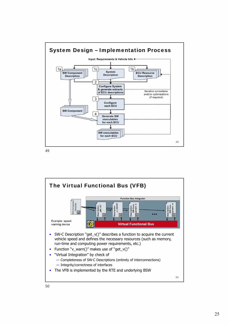
• SW-C Description “get_v()” describes a function to acquire the current vehicle speed and defines the necessary resources (such as memory, run-time and computing power requirements, etc.)
• Function “v_warn()” makes use of “get_v()”• “Virtual Integration” by check of
— Completeness of SW-C Descriptions (entirety of interconnections)— Integrity/correctness of interfaces
• The VFB is implemented by the RTE and underlying BSW50
49
50

26
AUTOSAR – Input Descriptions (1 of 3)Step 1a): Description of SW-C independently of HW
51
AUTOSAR – Input Descriptions (2 of 3)Step 1b): Description of HW independently of application software
52
51
52
27
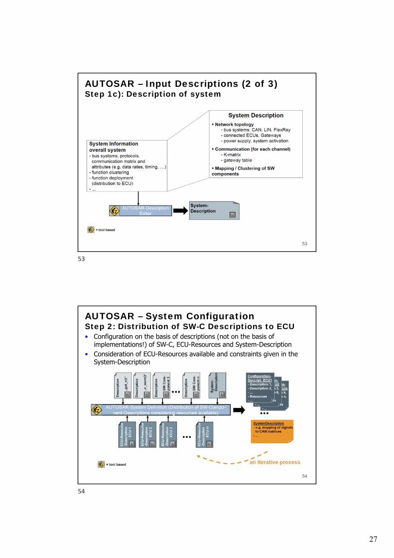
AUTOSAR – Input Descriptions (2 of 3)Step 1c): Description of system
53
AUTOSAR – System ConfigurationStep 2: Distribution of SW-C Descriptions to ECU• Configuration on the basis of descriptions (not on the basis of
implementations!) of SW-C, ECU-Resources and System-Description• Consideration of ECU-Resources available and constraints given in the
System-Description
54
53
54
28
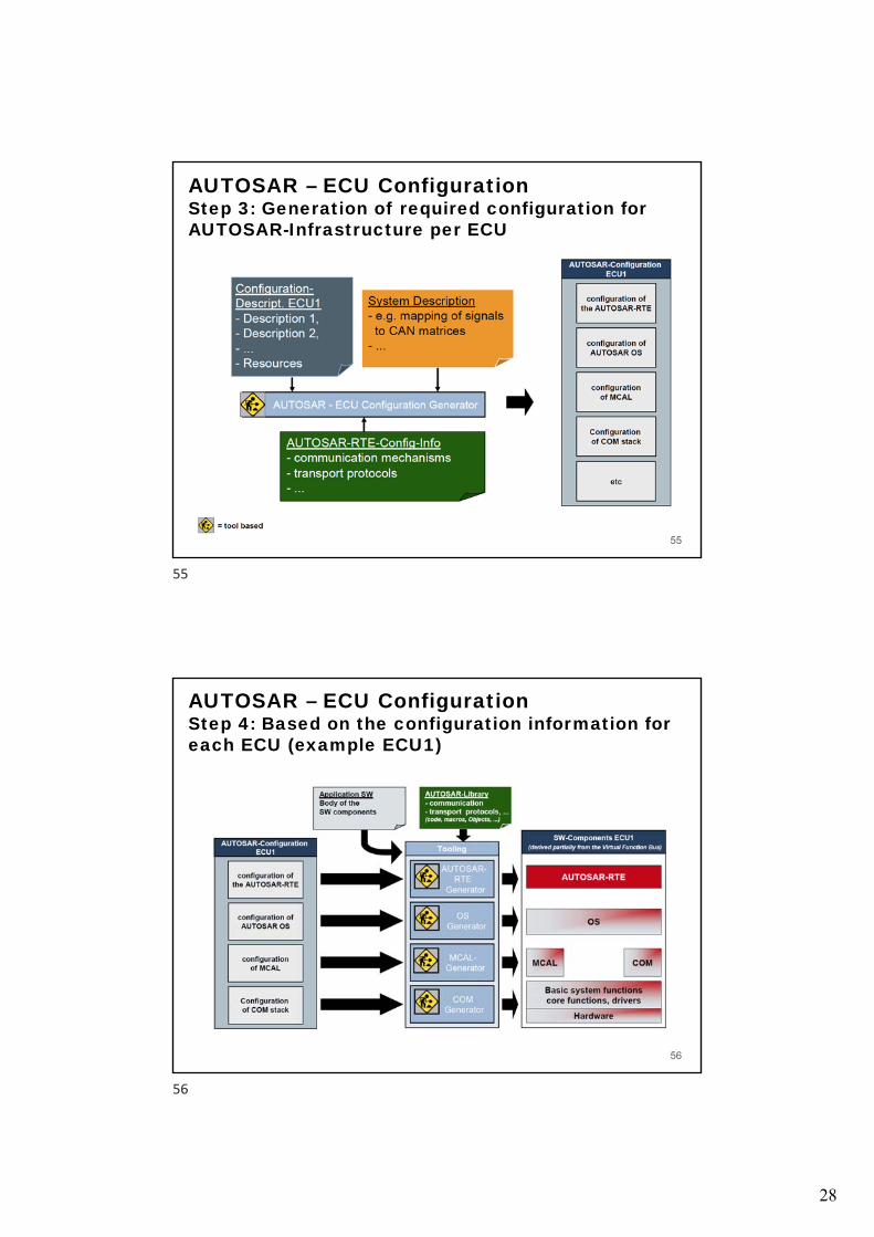
AUTOSAR – ECU ConfigurationStep 3: Generation of required configuration for AUTOSAR-Infrastructure per ECU
55
AUTOSAR – ECU ConfigurationStep 4: Based on the configuration information for each ECU (example ECU1)
56
55
56

29
AUTOSAR Methodology
57
AUTOSAR MetamodelFormal description of all methodology related information• The metamodel is modeled in UML
• The structure of the information can be clearly visualized
• The consistency of the information is guaranteed
• Using XML, a data exchange format can be generated automatically out of the metamodel
58
57
58
30
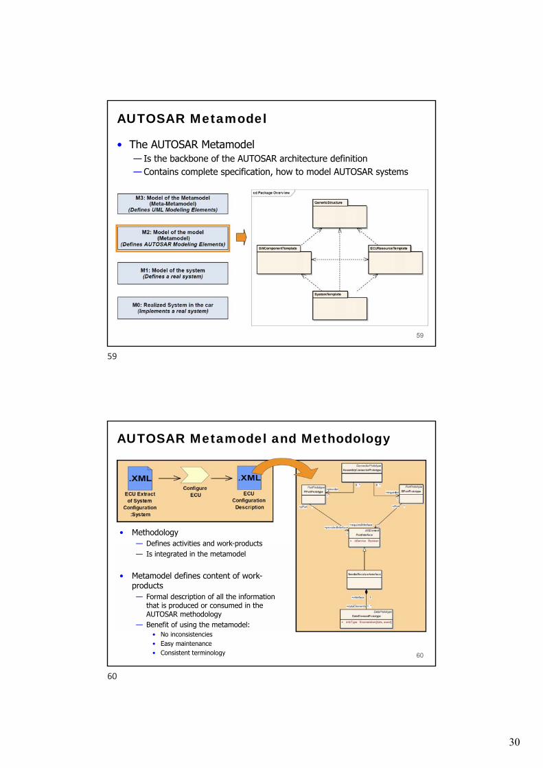
AUTOSAR Metamodel
• The AUTOSAR Metamodel— Is the backbone of the AUTOSAR architecture definition— Contains complete specification, how to model AUTOSAR systems
59
AUTOSAR Metamodel and Methodology
• Methodology— Defines activities and work-products— Is integrated in the metamodel
• Metamodel defines content of work-products— Formal description of all the information
that is produced or consumed in the AUTOSAR methodology
— Benefit of using the metamodel:• No inconsistencies• Easy maintenance• Consistent terminology 60
59
60

31
AUTOSAR Methodology - Conclusion
61
1 The E/E system architecture can be described by means of AUTOSAR.
2The meta model approach and the tool support for specifying the AUTOSAR information model allow working at the right level of abstraction.
3 A methodology to integrate AUTOSAR software modules has been designed.
4 AUTOSAR pushes the paradigm shift from an ECU based approach to a function based approach in automotive software development.
Main Concepts: Application Interfaces
Standardization approach Current stage of standardization
61
62
32
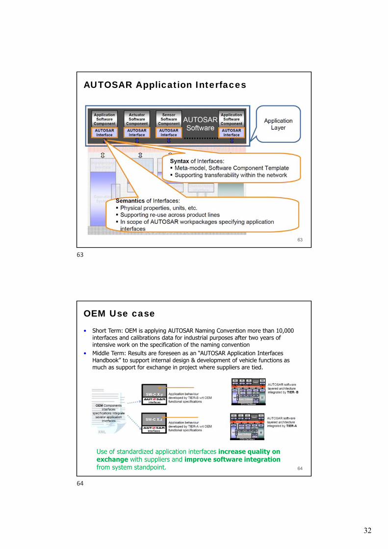
AUTOSAR Application Interfaces
63
OEM Use case
• Short Term: OEM is applying AUTOSAR Naming Convention more than 10,000 interfaces and calibrations data for industrial purposes after two years of intensive work on the specification of the naming convention
• Middle Term: Results are foreseen as an “AUTOSAR Application Interfaces Handbook” to support internal design & development of vehicle functions as much as support for exchange in project where suppliers are tied.
64
Use of standardized application interfaces increase quality on exchange with suppliers and improve software integrationfrom system standpoint.
63
64

33
Supplier Use case
• Specification of application interfaces will support integration of SW-Cs.
65
Use of 10.x application interfaces increase quality on integration, i.e. they prevent from inconsistencies.
Reusability
• To ease the re-use of software components across several OEMs, AUTOSAR proceeds on the standardization of the application interfaces agreed among the partners.
66
65
66
34
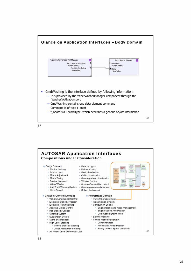
Glance on Application Interfaces – Body Domain
• CmdWashing is the interface defined by following information:— It is provided by the WiperWasherManager component through the
[Washer]Activation port— CmdWashing contains one data element command— Command is of type t_onoff— t_onoff is a RecordType, which describes a generic on/off information
67
AUTOSAR Application InterfacesCompositions under Consideration
68
67
68
35
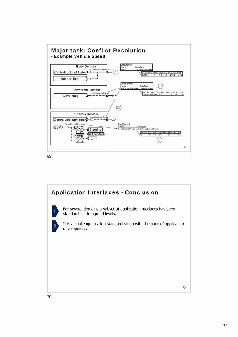
Major task: Conflict Resolution- Example Vehicle Speed
69
Application Interfaces - Conclusion
70
1 For several domains a subset of application interfaces has been standardized to agreed levels.
2 It is a challenge to align standardization with the pace of application development.
69
70