Embed Size (px)
Citation preview
Glossary AUTOSAR FO Release 1.0.0
1 of 95 Document ID 055: AUTOSAR_TR_Glossary
- AUTOSAR confidential -
Document Title Glossary Document Owner AUTOSAR
Document Responsibility AUTOSAR
Document Identification No 055
Document Classification Auxiliary
Document Status Final
Part of AUTOSAR Standard Foundation
Part of Standard Release 1.0.0
Document Change History Date Release Changed by Change Description
2016-11-30 1.0.0 AUTOSAR
Release
Management
--Migration of document to standard
“Foundation”--
Following terms added:
AUTOSAR Blueprint (3.19)
Bypassing (3.38)
Hook (3.137)
OS Event (3.174)
Post-build Hooking (3.185)
Pre-build Hooking (3.187)
Rapid Prototyping (RP) (3.195)
Rapid Prototyping Memory Interface
(3.196)
Rapid Prototyping Tool (3.197)
Reentrancy (3.200)
Standardized AUTOSAR Blueprint
(3.236)
Standardized Blueprint (3.238)
Following terms changed:
Asset (3.11)
Asynchronous Function (3.13)
AUTOSAR Application Interface
(3.17)
Availability (3.31)
ECU Abstraction Layer (3.77)
Feature (3.100)
Function (3.127)
Microcontroller Abstraction Layer
(MCAL) (3.162)
Glossary AUTOSAR FO Release 1.0.0
2 of 95 Document ID 055: AUTOSAR_TR_Glossary
- AUTOSAR confidential -
Document Change History Date Release Changed by Change Description
2015-07-31 4.2.2 AUTOSAR
Release
Management
Following terms changed:
ECU Abstraction Layer (3.77)
Standardized AUTOSAR Interface
(3.237)
Following terms removed:
Software Module
2014-10-31 4.2.1 AUTOSAR
Release
Management
Following terms changed:
Data Variant Coding (3.67)
OS-Application (3.173)
Post-build time configuration (3.186)
Standardized AUTOSAR Interface
(3.237)
2014-03-31 4.1.3 AUTOSAR
Release
Management
Extended Abbreviations (0)
Following terms changed:
Software Component (SW-C)
(3.229)
2013-03-15 4.1.1 AUTOSAR
Administration
Extended Abbreviations (0)
Following terms added:
Application Interface (3.4)
Asynchronous Functions (3.13)
AUTOSAR Application Interface
(3.17)
Dynamic PDU (3.73)
Life Cycle (3.155)
MetaDataLength (3.161)
PDU MetaData (3.179)
Pretended Networking (3.189)
Synchronous Functions (3.245)
2011-12-22 4.0.3 AUTOSAR
Administration
Extended Abbreviations (0)
Following terms added:
Callback (3.40)
Callout (3.41)
ECU (3.76)
2009-12-18 4.0.1 AUTOSAR
Administration
Following terms added:
AUTOSAR Partial Model (3.25)
Bus Wake-Up (3.37)
Empty Function (3.82)

Glossary AUTOSAR FO Release 1.0.0
3 of 95 Document ID 055: AUTOSAR_TR_Glossary
- AUTOSAR confidential -
Document Change History Date Release Changed by Change Description
2010-02-02 3.1.4 AUTOSAR
Administration
Following terms added:
Automotive Safety Integrity Levels
(ASIL) (3.16)
Bit Position (3.34)
Category 1 Interrupt (3.43)
Category 2 Interrupt (3.44)
Code Generator (3.50)
Coordinate (3.63)
E2E Profile (3.75)
Error Detection Rate (3.85)
Failure Rate (3.95)
ICC1 (Implementation Conformance
Class 1) (3.139)
ICC2 (Implementation Conformance
Class 2) (3.140)
ICC3 (Implementation Conformance
Class 3) (3.141)
Interrupt Frames (3.148)
Interrupt Handler (3.149)
Interrupt Logic (3.150)
Meta Model (3.159)
Mode (3.164)
Model (3.165)
Network Interface (NWI) (3.169)
NM Coordination Cluster (3.170)
NM Coordinator (3.171)
Rate Conversion (3.198)
Residual Error Rate (3.205)
SAE J1939 (3.213)
Safety Protocol (3.215)
Software Component Interface (SW-
CI) (3.230)
Synchronize (3.243)
Variability (3.256)
Variant (3.257)
Variation Binding (3.259)
Variation Binding Time (3.260)

Glossary AUTOSAR FO Release 1.0.0
4 of 95 Document ID 055: AUTOSAR_TR_Glossary
- AUTOSAR confidential -
Document Change History Date Release Changed by Change Description
Variation Definition Time (3.261)
Variation Point (3.262)
Formal adaptations
Legal disclaimer revised
2008-08-13 3.1.1 AUTOSAR
Administration
Legal disclaimer revised
2007-12-21 3.0.1 AUTOSAR
Administration
Following terms added:
Debugging (3.69)
Implementation Conformance
Statement (3.142)
Document meta information
extended
Small layout adaptations made
2007-01-24 2.1.15 AUTOSAR
Administration
“Advice for users” revised
“Revision Information” added
2007-11-28 2.1.14 AUTOSAR
Administration
Following terms added:
FlexRay (3.104)
Vendor ID (3.263)
Callback (3.40)
Interrupt frames (3.148)
Interrupt vector table(3.152)
Accreditation (3.1)
Accreditation Body (3.2)
Conformance Test Agency (3.59)
Assessment (3.10)
Surveillance (3.242)
Attestation (3.14)
(Conformance) Declaration (3.70)
First party and (3.101)
Third party (3.252)
Safety (3.214)
ECU Configuration (3.78)
ECU Configuration Description
(3.79)
Legal disclaimer revised
2006-05-16 2.0 AUTOSAR
Administration
removed and added some terms
rework of several descriptions
and some formal changes

Glossary AUTOSAR FO Release 1.0.0
5 of 95 Document ID 055: AUTOSAR_TR_Glossary
- AUTOSAR confidential -
Document Change History Date Release Changed by Change Description
2005-05-31 1.0 AUTOSAR
Administration
Initial Release
Glossary AUTOSAR FO Release 1.0.0
6 of 95 Document ID 055: AUTOSAR_TR_Glossary
- AUTOSAR confidential -
Disclaimer This specification and the material contained in it, as released by AUTOSAR, is for the purpose of information only. AUTOSAR and the companies that have contributed to it shall not be liable for any use of the specification. The material contained in this specification is protected by copyright and other types of Intellectual Property Rights. The commercial exploitation of the material contained in this specification requires a license to such Intellectual Property Rights. This specification may be utilized or reproduced without any modification, in any form or by any means, for informational purposes only. For any other purpose, no part of the specification may be utilized or reproduced, in any form or by any means, without permission in writing from the publisher. The AUTOSAR specifications have been developed for automotive applications only. They have neither been developed, nor tested for non-automotive applications. The word AUTOSAR and the AUTOSAR logo are registered trademarks.
Advice for users AUTOSAR specifications may contain exemplary items (exemplary reference models, "use cases", and/or references to exemplary technical solutions, devices, processes or software). Any such exemplary items are contained in the specifications for illustration purposes only, and they themselves are not part of the AUTOSAR Standard. Neither their presence in such specifications, nor any later documentation of AUTOSAR conformance of products actually implementing such exemplary items, imply that intellectual property rights covering such exemplary items are licensed under the same rules as applicable to the AUTOSAR Standard.

Glossary AUTOSAR FO Release 1.0.0
7 of 95 Document ID 055: AUTOSAR_TR_Glossary
- AUTOSAR confidential -
Table of Contents
0 Abbreviations........................................................................................................ 13
1 Introduction ........................................................................................................... 17
2 How to read this document .................................................................................. 18
2.1 <Definition> ................................................................................................... 18
3 Definitions ............................................................................................................. 19
3.1 Accreditation ................................................................................................. 19
3.2 Accreditation Body ........................................................................................ 19
3.3 Application .................................................................................................... 19
3.4 Application Interface ..................................................................................... 19
3.5 Application Programming Interface (API) ..................................................... 20
3.6 Application Software Component ................................................................. 20
3.7 Architecture ................................................................................................... 20
3.8 Artifact ........................................................................................................... 20
3.9 Asserted Property ......................................................................................... 21
3.10 Assessment .................................................................................................. 21
3.11 Asset ............................................................................................................. 21
3.12 Asynchronous Communication ..................................................................... 21
3.13 Asynchronous Function ................................................................................ 22
3.14 Attestation ..................................................................................................... 22
3.15 Atomic Software Component ........................................................................ 22
3.16 Automotive Safety Integrity Levels (ASIL) .................................................... 22
3.17 AUTOSAR Application Interface ................................................................... 23
3.18 AUTOSAR Authoring Tool ............................................................................ 23
3.19 AUTOSAR Blueprint ..................................................................................... 23
3.20 AUTOSAR Converter Tool ........................................................................... 23
3.21 AUTOSAR Definition .................................................................................... 24
3.22 AUTOSAR Interface ..................................................................................... 24
3.23 AUTOSAR Metamodel .................................................................................. 24
3.24 AUTOSAR Model .......................................................................................... 24
3.25 AUTOSAR Partial Model .............................................................................. 25
3.26 AUTOSAR Processor Tool ........................................................................... 25
3.27 AUTOSAR Service ....................................................................................... 25
3.28 AUTOSAR Tool ............................................................................................. 25
3.29 AUTOSAR XML description ......................................................................... 26
3.30 AUTOSAR XML Schema .............................................................................. 26
3.31 Availability ..................................................................................................... 26
3.32 Basic Software (BSW) .................................................................................. 26
3.33 Basic Software Module ................................................................................. 27
3.34 Bit Position .................................................................................................... 27
3.35 Blueprint ........................................................................................................ 27
3.36 Bulk Data ...................................................................................................... 27
3.37 Bus Wake-Up ................................................................................................ 28
3.38 Bypassing ..................................................................................................... 28
3.39 Calibration ..................................................................................................... 28
3.40 Callback ........................................................................................................ 29
Glossary AUTOSAR FO Release 1.0.0
8 of 95 Document ID 055: AUTOSAR_TR_Glossary
- AUTOSAR confidential -
3.41 Callout ........................................................................................................... 29
3.42 Call Point ....................................................................................................... 29
3.43 Category 1 Interrupt ...................................................................................... 30
3.44 Category 2 Interrupt ...................................................................................... 30
3.45 Causality of Transmission ............................................................................ 30
3.46 Client ............................................................................................................. 31
3.47 Client-Server Communication ....................................................................... 31
3.48 Client-Server Interface .................................................................................. 31
3.49 Cluster Signal ................................................................................................ 31
3.50 Code Generator ............................................................................................ 32
3.51 Code Variant Coding .................................................................................... 32
3.52 Communication Attribute .............................................................................. 32
3.53 Complex Driver (CDD) .................................................................................. 32
3.54 Composition .................................................................................................. 33
3.55 Compositionality............................................................................................ 33
3.56 Conditioned Signal ........................................................................................ 33
3.57 Configuration ................................................................................................. 34
3.58 Confirmation .................................................................................................. 34
3.59 Conformance Test Agency (CTA) ................................................................ 34
3.60 Conformance Test Suite (CTS) .................................................................... 34
3.61 Connector ..................................................................................................... 35
3.62 Control Flow .................................................................................................. 35
3.63 Coordinate .................................................................................................... 35
3.64 Data ............................................................................................................... 35
3.65 Data Element ................................................................................................ 35
3.66 Data Flow ...................................................................................................... 36
3.67 Data Variant Coding ..................................................................................... 36
3.68 Deadline ........................................................................................................ 36
3.69 Debugging ..................................................................................................... 36
3.70 (Conformance) Declaration .......................................................................... 37
3.71 Dependability ................................................................................................ 37
3.72 Diagnostic Event ........................................................................................... 37
3.73 Dynamic PDU ............................................................................................... 37
3.74 Dynamic Routing........................................................................................... 38
3.75 E2E Profile .................................................................................................... 38
3.76 ECU ............................................................................................................... 38
3.77 ECU Abstraction Layer ................................................................................. 38
3.78 ECU Configuration ........................................................................................ 39
3.79 ECU Configuration Description ..................................................................... 39
3.80 Electronic Control Unit (ECU) ....................................................................... 39
3.81 Electrical Signal ............................................................................................ 40
3.82 Empty Function ............................................................................................. 40
3.83 Entry Point .................................................................................................... 40
3.84 Error .............................................................................................................. 40
3.85 Error Detection Rate ..................................................................................... 41
3.86 Event ............................................................................................................. 41
3.87 Event Message (SOME/IP) .......................................................................... 41
3.88 Execution Time ............................................................................................. 41
3.89 Exit Point ....................................................................................................... 42
3.90 Fail-degraded ................................................................................................ 42

Glossary AUTOSAR FO Release 1.0.0
9 of 95 Document ID 055: AUTOSAR_TR_Glossary
- AUTOSAR confidential -
3.91 Fail-operational ............................................................................................. 42
3.92 Fail-safe ........................................................................................................ 42
3.93 Fail-silent ....................................................................................................... 43
3.94 Failure ........................................................................................................... 43
3.95 Failure Rate .................................................................................................. 43
3.96 Fault .............................................................................................................. 43
3.97 Fault Detection .............................................................................................. 44
3.98 Fault Reaction ............................................................................................... 44
3.99 Fault Tolerance ............................................................................................. 44
3.100 Feature ...................................................................................................... 44
3.101 First party .................................................................................................. 45
3.102 Flag ............................................................................................................ 45
3.103 FlexRay Base Cycle .................................................................................. 45
3.104 FlexRay Bus .............................................................................................. 46
3.105 FlexRay Cell .............................................................................................. 46
3.106 FlexRay Channel ....................................................................................... 46
3.107 FlexRay Cluster ......................................................................................... 47
3.108 FlexRay Cycle ........................................................................................... 47
3.109 FlexRay Cycle Number ............................................................................. 47
3.110 FlexRay Cycle Offset ................................................................................ 47
3.111 FlexRay Cycle Repetition .......................................................................... 48
3.112 FlexRay Frame .......................................................................................... 48
3.113 FlexRay Global Time ................................................................................. 48
3.114 FlexRay L-PDU ......................................................................................... 49
3.115 FlexRay L-PDU-Identifier .......................................................................... 49
3.116 FlexRay L-SDU-Identifier .......................................................................... 50
3.117 FlexRay Matrix .......................................................................................... 50
3.118 FlexRay Network ....................................................................................... 51
3.119 FlexRay Node............................................................................................ 51
3.120 FlexRay Physical Communication Link ..................................................... 51
3.121 FlexRay Slot .............................................................................................. 52
3.122 FlexRay Slot Multiplexing .......................................................................... 52
3.123 FlexRay Slot Number ................................................................................ 53
3.124 FlexRay Star .............................................................................................. 53
3.125 Frame ........................................................................................................ 54
3.126 Frame PDU ............................................................................................... 54
3.127 Function ..................................................................................................... 54
3.128 Functional Network ................................................................................... 55
3.129 Functional Unit .......................................................................................... 55
3.130 Functionality .............................................................................................. 55
3.131 Gateway .................................................................................................... 55
3.132 Gateway ECU............................................................................................ 55
3.133 Hardware Connection ............................................................................... 56
3.134 Hardware Element .................................................................................... 56
3.135 Hardware Interrupt .................................................................................... 56
3.136 Hardware Port ........................................................................................... 56
3.137 Hook .......................................................................................................... 57
3.138 I-PDU ......................................................................................................... 57
3.139 ICC1 (Implementation Conformance Class 1) .......................................... 57
3.140 ICC2 (Implementation Conformance Class 2) .......................................... 58

Glossary AUTOSAR FO Release 1.0.0
10 of 95 Document ID 055: AUTOSAR_TR_Glossary
- AUTOSAR confidential -
3.141 ICC3 (Implementation Conformance Class 3) .......................................... 59
3.142 Implementation Conformance Statement ................................................. 59
3.143 Indication ................................................................................................... 60
3.144 Integration ................................................................................................. 60
3.145 Integration Code ........................................................................................ 61
3.146 Interface .................................................................................................... 61
3.147 Interrupt ..................................................................................................... 61
3.148 Interrupt Frames ........................................................................................ 61
3.149 Interrupt Handler ....................................................................................... 62
3.150 Interrupt Logic ........................................................................................... 62
3.151 Interrupt Service Routine (ISR) ................................................................. 62
3.152 Interrupt Vector Table ............................................................................... 62
3.153 Invalid Flag ................................................................................................ 62
3.154 Invalid Value of Signal............................................................................... 63
3.155 Life Cycle ................................................................................................... 63
3.156 Link time configuration .............................................................................. 63
3.157 Mapping ..................................................................................................... 63
3.158 MCAL Signal ............................................................................................. 64
3.159 Meta Model ................................................................................................ 64
3.160 Metadata ................................................................................................... 64
3.161 MetaDataLength ........................................................................................ 64
3.162 Microcontroller Abstraction Layer (MCAL) ................................................ 65
3.163 Mistake ...................................................................................................... 65
3.164 Mode.......................................................................................................... 65
3.165 Model ......................................................................................................... 66
3.166 Multimedia Stream .................................................................................... 66
3.167 Multiple Configuration Sets ....................................................................... 66
3.168 Multiplexed PDU ....................................................................................... 67
3.169 Network Interface (NWI) ........................................................................... 67
3.170 NM Coordination Cluster ........................................................................... 68
3.171 NM Coordinator ......................................................................................... 68
3.172 Notification ................................................................................................. 68
3.173 OS-Application .......................................................................................... 68
3.174 OS Event ................................................................................................... 69
3.175 Partial Model ............................................................................................. 69
3.176 Partitioning ................................................................................................ 69
3.177 PCI ............................................................................................................. 69
3.178 PDU ........................................................................................................... 70
3.179 PDU MetaData .......................................................................................... 70
3.180 PDU Timeout ............................................................................................. 71
3.181 Peripheral Hardware ................................................................................. 71
3.182 Personalization .......................................................................................... 71
3.183 Port ............................................................................................................ 71
3.184 Port Interface ............................................................................................. 72
3.185 Post-build Hooking .................................................................................... 72
3.186 Post-build time configuration ..................................................................... 72
3.187 Pre-build Hooking ...................................................................................... 72
3.188 Pre-Compile time configuration ................................................................. 72
3.189 Pretended Networking............................................................................... 73
3.190 Private Interface (API 3) ............................................................................ 73

Glossary AUTOSAR FO Release 1.0.0
11 of 95 Document ID 055: AUTOSAR_TR_Glossary
- AUTOSAR confidential -
3.191 Probability of failure ................................................................................... 73
3.192 Procedure Call........................................................................................... 73
3.193 Process ..................................................................................................... 74
3.194 Provide Port ............................................................................................... 74
3.195 Rapid Prototyping (RP) ............................................................................. 74
3.196 Rapid Prototyping Memory Interface ........................................................ 74
3.197 Rapid Prototyping Tool.............................................................................. 75
3.198 Rate Conversion ....................................................................................... 75
3.199 Redundancy .............................................................................................. 75
3.200 Reentrancy ................................................................................................ 75
3.201 Reliability ................................................................................................... 76
3.202 Relocatability ............................................................................................. 76
3.203 Require Port .............................................................................................. 76
3.204 Required property ..................................................................................... 76
3.205 Residual Error Rate ................................................................................... 77
3.206 Resource ................................................................................................... 77
3.207 Resource-Management............................................................................. 77
3.208 Response Time ......................................................................................... 77
3.209 Risk ............................................................................................................ 78
3.210 Robustness ............................................................................................... 78
3.211 RTE Event ................................................................................................. 78
3.212 Runnable Entity ......................................................................................... 78
3.213 SAE J1939 ................................................................................................ 79
3.214 Safety ........................................................................................................ 79
3.215 Safety Protocol .......................................................................................... 79
3.216 Sample Application ................................................................................... 79
3.217 Scalability .................................................................................................. 80
3.218 Scheduler .................................................................................................. 80
3.219 SDU ........................................................................................................... 80
3.220 Security ..................................................................................................... 80
3.221 Sender-Receiver Communication ............................................................. 81
3.222 Sender-Receiver Interface ........................................................................ 81
3.223 Sensor/Actuator SW-Component ............................................................. 81
3.224 Server ........................................................................................................ 81
3.225 Service ...................................................................................................... 82
3.226 Service Port ............................................................................................... 82
3.227 Services Layer........................................................................................... 82
3.228 Shipping .................................................................................................... 82
3.229 Software Component (SW-C) ................................................................... 83
3.230 Software Component Interface (SW-CI) ................................................... 83
3.231 Software Configuration.............................................................................. 83
3.232 Software Interrupt ...................................................................................... 84
3.233 Software Signal ......................................................................................... 84
3.234 Special Periphery Access ......................................................................... 84
3.235 Standard Periphery Access ...................................................................... 84
3.236 Standardized AUTOSAR Blueprint ........................................................... 85
3.237 Standardized AUTOSAR Interface ........................................................... 85
3.238 Standardized Blueprint .............................................................................. 85
3.239 Standardized Interface .............................................................................. 85
3.240 Standard Software .................................................................................... 86
Glossary AUTOSAR FO Release 1.0.0
12 of 95 Document ID 055: AUTOSAR_TR_Glossary
- AUTOSAR confidential -
3.241 Static Configuration ................................................................................... 86
3.242 Surveillance ............................................................................................... 86
3.243 Synchronize ............................................................................................... 86
3.244 Synchronous Communication ................................................................... 87
3.245 Synchronous Function .............................................................................. 87
3.246 System ...................................................................................................... 87
3.247 System Constraint ..................................................................................... 87
3.248 System Signal ........................................................................................... 88
3.249 Task ........................................................................................................... 88
3.250 Technical Signal ........................................................................................ 88
3.251 Template ................................................................................................... 88
3.252 Third party ................................................................................................. 89
3.253 Timeout ..................................................................................................... 89
3.254 Use Case ................................................................................................... 89
3.255 Validation ................................................................................................... 89
3.256 Variability ................................................................................................... 90
3.257 Variant ....................................................................................................... 90
3.258 Variant Coding........................................................................................... 90
3.259 Variation Binding ....................................................................................... 90
3.260 Variation Binding Time .............................................................................. 91
3.261 Variation Definition Time ........................................................................... 91
3.262 Variation Point ........................................................................................... 91
3.263 Vendor ID .................................................................................................. 91
3.264 Verification ................................................................................................. 92
3.265 VFB View ................................................................................................... 92
3.266 Virtual Functional Bus (VFB) ..................................................................... 92
3.267 Virtual Integration ...................................................................................... 92
3.268 Worst Case Execution Time ..................................................................... 93
3.269 Worst Case Response Time ..................................................................... 93
Annex 1: Literature ...................................................................................................... 94
Glossary AUTOSAR FO Release 1.0.0
13 of 95 Document ID 055: AUTOSAR_TR_Glossary
- AUTOSAR confidential -
0 Abbreviations
Abbreviation Description
ADC Analog Digital Converter
AMM Application Mode Management
API Application Programming Interface
ARP Address Resolution Protocol
ASAM Association for Standardization of Automation and Measuring systems
ASIL Automotive Safety Integrity Levels
ASW Application SoftWare
AUTOSAR AUTomotive Open System Architecture
BFx Bitfield functions for fixed point
BSW Basic SoftWare
BSWM Basic SoftWare Mode manager
BSWMD Basic SoftWare Module Description
CAN Controller Area Network
CDD Complex Driver
COM Communication
CPU Central Processing Unit
CRC Cyclic Redundancy Check
CTA Conformance Test Agency
CTS Conformance Test Suite
DAC Digital to Analog Converter
DEM Diagnostic Event Manager
DET Development Error Tracer
DHCP Dynamic Host Configuration Protocol
DIO Digital Input/Output
DLC Data Length Code
DoIP Diagnostics over Internet Protocol
DTD Document Type Definition
E2E End to End
ECU Electronic Control Unit
EEPROM Electrically Erasable Programmable Read-Only Memory
EFx Extended Mathematical library – Fixed point
Glossary AUTOSAR FO Release 1.0.0
14 of 95 Document ID 055: AUTOSAR_TR_Glossary
- AUTOSAR confidential -
FIFO First In First Out
FPU Floating Point Unit
FW Fire Wire
GPT General Purpose Timer
GSM Global System for Mobile Communication
HW Hardware
I-PDU Interaction Layer Protocol Data Unit
ICC Implementation Conformance Class
ICMP Internet Control Message Protocol
ICOM Intelligent COMmunication controller
ICU Input Capture Unit
IEC International Electrotechnical Commission
IFI Interpolation Floating point
IFx Interpolation Fixed point
IO Input/ Output
ISR Interrupt Service Routine
L-PDU Protocol Data Unit of the data Link layer
L-SDU SDU of the data Link layer
LIFO Last In First Out
LIN Local Interconnected Network
LSB Least Significant Bit
C MicroController
MCAL MicroController Abstraction Layer
MCU Micro Controller Unit
MFI Mathematical Floating point
MFx Math – Fixed Point
MIPS Million Instructions Per Second
MMU Memory Management Unit
MMI Man Machine Interface
MOST Media Oriented Systems Transport
P MicroProcessor
MPU Memory Protection Unit
MSB Most Significant Bit
N-PDU Protocol Data Unit of the Network layer (transport protocols)
Glossary AUTOSAR FO Release 1.0.0
15 of 95 Document ID 055: AUTOSAR_TR_Glossary
- AUTOSAR confidential -
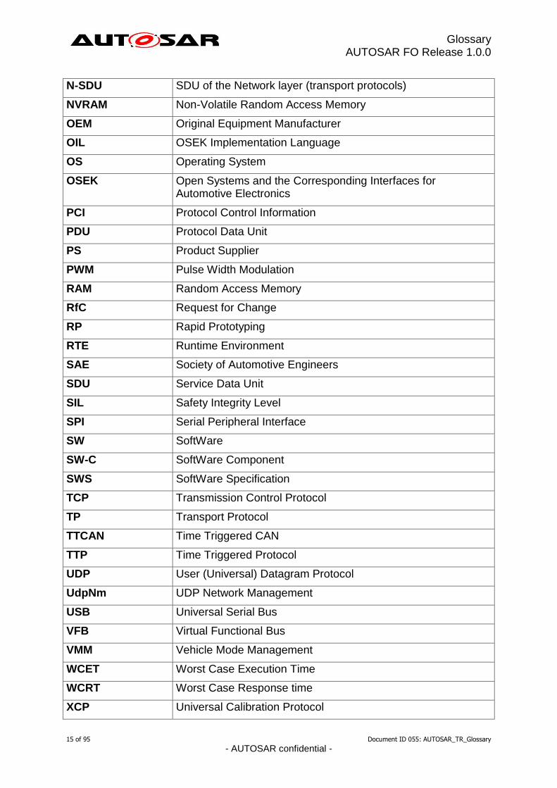
N-SDU SDU of the Network layer (transport protocols)
NVRAM Non-Volatile Random Access Memory
OEM Original Equipment Manufacturer
OIL OSEK Implementation Language
OS Operating System
OSEK Open Systems and the Corresponding Interfaces for Automotive Electronics
PCI Protocol Control Information
PDU Protocol Data Unit
PS Product Supplier
PWM Pulse Width Modulation
RAM Random Access Memory
RfC Request for Change
RP Rapid Prototyping
RTE Runtime Environment
SAE Society of Automotive Engineers
SDU Service Data Unit
SIL Safety Integrity Level
SPI Serial Peripheral Interface
SW SoftWare
SW-C SoftWare Component
SWS SoftWare Specification
TCP Transmission Control Protocol
TP Transport Protocol
TTCAN Time Triggered CAN
TTP Time Triggered Protocol
UDP User (Universal) Datagram Protocol
UdpNm UDP Network Management
USB Universal Serial Bus
VFB Virtual Functional Bus
VMM Vehicle Mode Management
WCET Worst Case Execution Time
WCRT Worst Case Response time
XCP Universal Calibration Protocol

Glossary AUTOSAR FO Release 1.0.0
16 of 95 Document ID 055: AUTOSAR_TR_Glossary
- AUTOSAR confidential -
XML Extensible Markup Language

Glossary AUTOSAR FO Release 1.0.0
17 of 95 Document ID 055: AUTOSAR_TR_Glossary
- AUTOSAR confidential -
1 Introduction This document is the overall glossary of AUTOSAR. It contains definitions of all major terms and notions used within AUTOSAR. It does not claim to be complete and please keep in mind that some WPs have more specific terms defined within their domain specific glossary.
Glossary AUTOSAR FO Release 1.0.0
18 of 95 Document ID 055: AUTOSAR_TR_Glossary
- AUTOSAR confidential -
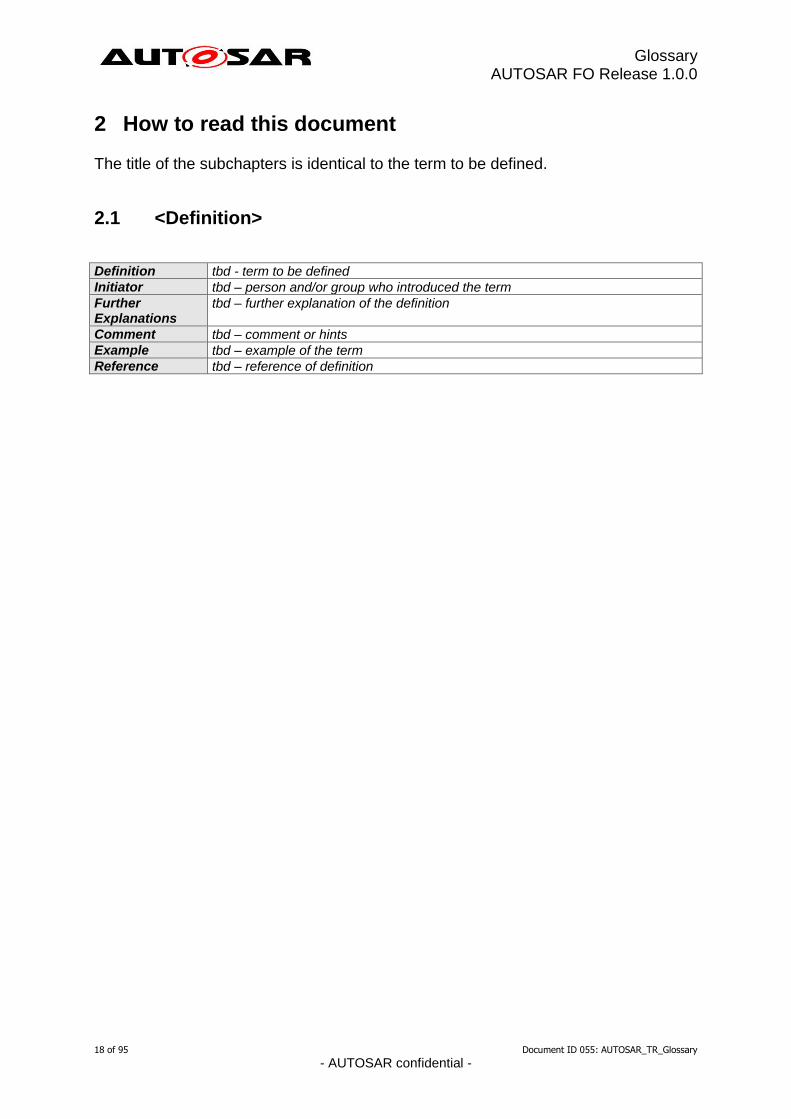
2 How to read this document The title of the subchapters is identical to the term to be defined.
2.1 <Definition>
Definition tbd - term to be defined
Initiator tbd – person and/or group who introduced the term
Further Explanations
tbd – further explanation of the definition
Comment tbd – comment or hints
Example tbd – example of the term
Reference tbd – reference of definition
Glossary AUTOSAR FO Release 1.0.0
19 of 95 Document ID 055: AUTOSAR_TR_Glossary
- AUTOSAR confidential -
3 Definitions
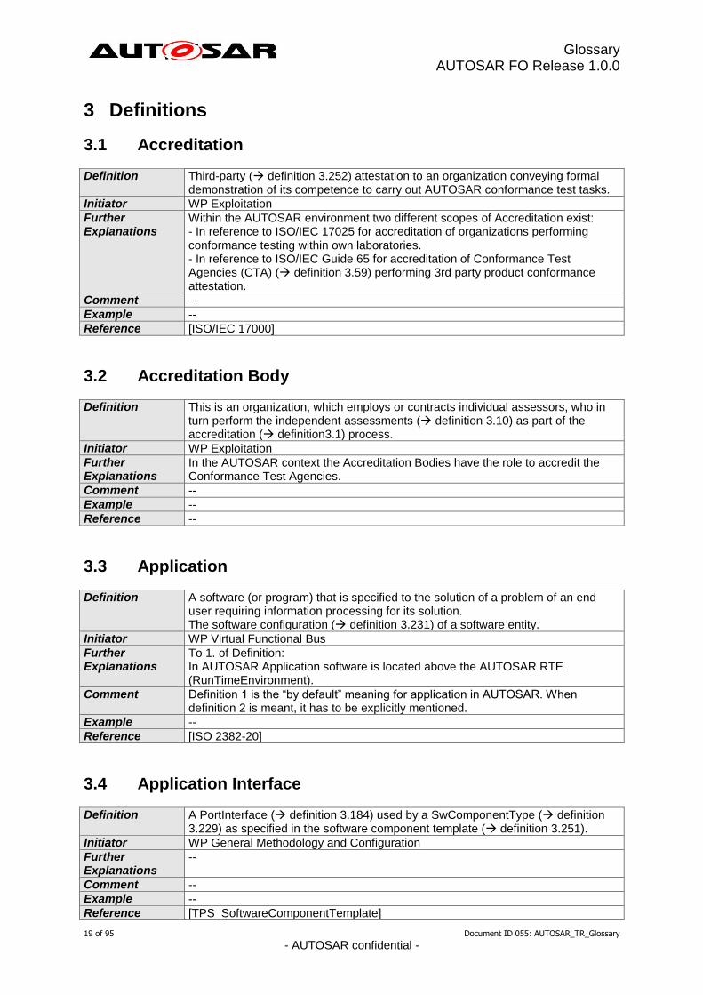
3.1 Accreditation
Definition Third-party ( definition 3.252) attestation to an organization conveying formal demonstration of its competence to carry out AUTOSAR conformance test tasks.
Initiator WP Exploitation
Further Explanations
Within the AUTOSAR environment two different scopes of Accreditation exist: - In reference to ISO/IEC 17025 for accreditation of organizations performing conformance testing within own laboratories. - In reference to ISO/IEC Guide 65 for accreditation of Conformance Test Agencies (CTA) ( definition 3.59) performing 3rd party product conformance attestation.
Comment --
Example --
Reference [ISO/IEC 17000]
3.2 Accreditation Body
Definition This is an organization, which employs or contracts individual assessors, who in turn perform the independent assessments ( definition 3.10) as part of the accreditation ( definition3.1) process.
Initiator WP Exploitation
Further Explanations
In the AUTOSAR context the Accreditation Bodies have the role to accredit the Conformance Test Agencies.
Comment --
Example --
Reference --
3.3 Application
Definition A software (or program) that is specified to the solution of a problem of an end user requiring information processing for its solution. The software configuration ( definition 3.231) of a software entity.
Initiator WP Virtual Functional Bus
Further Explanations
To 1. of Definition: In AUTOSAR Application software is located above the AUTOSAR RTE (RunTimeEnvironment).
Comment Definition 1 is the “by default” meaning for application in AUTOSAR. When definition 2 is meant, it has to be explicitly mentioned.
Example --
Reference [ISO 2382-20]
3.4 Application Interface
Definition A PortInterface ( definition 3.184) used by a SwComponentType ( definition 3.229) as specified in the software component template ( definition 3.251).
Initiator WP General Methodology and Configuration
Further Explanations
--
Comment --
Example --
Reference [TPS_SoftwareComponentTemplate]
Glossary AUTOSAR FO Release 1.0.0
20 of 95 Document ID 055: AUTOSAR_TR_Glossary
- AUTOSAR confidential -
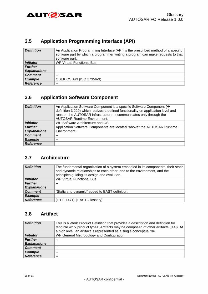
3.5 Application Programming Interface (API)
Definition An Application Programming Interface (API) is the prescribed method of a specific software part by which a programmer writing a program can make requests to that software part.
Initiator WP Virtual Functional Bus
Further Explanations
--
Comment --
Example OSEK OS API (ISO 17356-3)
Reference --
3.6 Application Software Component
Definition An Application Software Component is a specific Software Component ( definition 3.229) which realizes a defined functionality on application level and runs on the AUTOSAR infrastructure. It communicates only through the AUTOSAR Runtime Environment.
Initiator WP Software Architecture and OS
Further Explanations
Application Software Components are located "above" the AUTOSAR Runtime Environment.
Comment --
Example --
Reference --
3.7 Architecture
Definition The fundamental organization of a system embodied in its components, their static and dynamic relationships to each other, and to the environment, and the principles guiding its design and evolution.
Initiator WP Virtual Functional Bus
Further Explanations
--
Comment “Static and dynamic” added to EAST definition.
Example --
Reference [IEEE 1471], [EAST-Glossary]
3.8 Artifact
Definition This is a Work Product Definition that provides a description and definition for tangible work product types. Artifacts may be composed of other artifacts ([14]). At a high level, an artifact is represented as a single conceptual file.
Initiator WP General Methodology and Configuration
Further Explanations
--
Comment --
Example --
Reference --
Glossary AUTOSAR FO Release 1.0.0
21 of 95 Document ID 055: AUTOSAR_TR_Glossary
- AUTOSAR confidential -
3.9 Asserted Property
Definition A property or quality of a design entity (e.g. SW component or system) is asserted, if the design entity guarantees that this property or quality is fulfilled.
Initiator WP Body and Comfort
Further Explanations
A property or quality of a design unit can be asserted by the design unit itself or in combination with another design unit.
Comment --
Example If the worst case execution time of a task (w.r.t. a certain CPU etc.) is asserted to be 3 ms, the execution time of this task will under any circumstances be less than or equal to 3 ms.
Reference Compare required property ( definition 3.204)
3.10 Assessment
Definition Activity conducted by an assessor to demonstrate that the assessed organization fulfills the set requirements.
Initiator WP Exploitation
Further Explanations
Within the AUTOSAR context after the initial assessment a new full-set assessment will be repeated every 4 years. In between, surveillances ( definition 3.242) take place once a year.
Comment --
Example --
Reference [ISO/IEC 17011]
3.11 Asset
Definition An item that has been designed for use in multiple contexts.
Initiator WP Virtual Functional Bus
Further Explanations
--
Comment --
Example An asset can be design, specifications, source code, documentation, test suits, manual procedures, etc.. From a security perspective anything that has a value to any of the stakeholders such as critical data (information, software) and critical functions, that could potentially be subject to attacks and possibly, but not necessarily, motivates countermeasures.
Reference [IEEE 1517], [EAST-Glossary]
3.12 Asynchronous Communication
Definition Asynchronous communication does not block the sending software entity. The sending software entity continues its operation without getting a response from the communication partner(s).
Initiator WP Virtual Functional Bus
Further Explanations
There could be an acknowledgement by the communication system about the sending of the information. A later response to the sending software entity is possible.
Comment --
Example --
Reference --
Glossary AUTOSAR FO Release 1.0.0
22 of 95 Document ID 055: AUTOSAR_TR_Glossary
- AUTOSAR confidential -
3.13 Asynchronous Function
Definition A Function ( definition 3.127 #2) is called asynchronous if the described functionality is not guaranteed to be completed the moment the function returns to the caller.
Initiator WP Software Architecture and OS
Further Explanations
--
Comment --
Example --
Reference --
3.14 Attestation
Definition Issue of a statement, based on a decision following a review, that fulfillment of specified requirements has been demonstrated.
Initiator WP Exploitation
Further Explanations
The resulting statement, referred to in the International Standard as a "statement of conformity", conveys the assurance that the specified requirements have been fulfilled. Such an assurance does not, of itself, afford contractual or other legal guarantees.
Comment --
Example Attestation of product conformance given by a third party like a CTA ( definition 3.59). Attestation of product conformance given by a first party like the Product Supplier (also called declaration).
Reference [ISO/IEC 17000]
3.15 Atomic Software Component
Definition Non-composed Software-Component.
Initiator WP Software Architecture and OS
Further Explanations
An Atomic Software Component might access HW or not, therefore not all Atomic SW-Cs are relocatable.
Comment --
Example Application Software-Component, Complex Driver
Reference --
3.16 Automotive Safety Integrity Levels (ASIL)
Definition Automotive Safety Integrity Levels (ASIL) are used within ISO 26262 to express the level of risk reduction required to prevent a specific hazard, with ASIL D representing the highest and ASIL A the lowest. The ASIL is assigned to the according safety goal and inherited to the safety requirements derived from it.
Initiator WP Functional Safety and Processes
Further Explanations
--
Comment --
Example --
Reference --
Glossary AUTOSAR FO Release 1.0.0
23 of 95 Document ID 055: AUTOSAR_TR_Glossary
- AUTOSAR confidential -
3.17 AUTOSAR Application Interface
Definition A set of Blueprints ( definition 3.35) which are standardized by AUTOSAR and which can be used for creating AUTOSAR Interfaces ( definition 3.22) of an Application ( definition 3.3). AUTOSAR interfaces that are derived from Standardized Blueprints ( definition 3.238) are Standardized AUTOSAR Interfaces ( definition 3.237).
Initiator WP General Methodology and Configuration
Further Explanations
--
Comment --
Example --
Reference [EXP_AIUserGuide]
3.18 AUTOSAR Authoring Tool
Definition An AUTOSAR Tool used to create and modify AUTOSAR XML Descriptions ( definition 3.29).
Initiator WP Authoring Tools
Further Explanations
--
Comment --
Example System Description Editor
Reference --
3.19 AUTOSAR Blueprint
Definition An AUTOSAR Blueprint is a Blueprint ( definition 3.35) for an AUTOSAR element. It also includes that it is specified within the AUTOSAR project which attributes are mandatory to be specified for the blueprint of a specific class of AUTOSAR element types as well as how to derive an AUTOSAR object from that blueprint.
Initiator WP Application Interfaces
Further Explanations
The AUTOSAR meta-model supports the pre-definition of model elements taken as the basis for further modeling. These pre-definitions are called blueprints. [TPS_STDT_00002]
Comment --
Example --
Reference [TPS Standardization Template]
3.20 AUTOSAR Converter Tool
Definition An AUTOSAR Tool used to create AUTOSAR XML files by converting information from other AUTOSAR XML files.
Initiator WP General Methodology and Configuration
Further Explanations
--
Comment --
Example ECU Flattener
Reference --

Glossary AUTOSAR FO Release 1.0.0
24 of 95 Document ID 055: AUTOSAR_TR_Glossary
- AUTOSAR confidential -
3.21 AUTOSAR Definition
Definition This is the definition of parameters which can have values. One could say that the parameter values are instances of the definitions. But in the meta model hierarchy of AUTOSAR, definitions are also instances of the meta model and therefore considered as a description.
Initiator WP General Methodology and Configuration
Further Explanations
--
Comment --
Example EcucParameterDef, PostBuildVariantCriterion, SwSystemconst
Reference --
3.22 AUTOSAR Interface
Definition The AUTOSAR Interface of a software component ( definition 3.229) refers to the collection of all ports ( definition 3.183) of that component through which it interacts with other components.
Initiator WP Virtual Functional Bus
Further Explanations
--
Comment Note that an AUTOSAR Interface is different from a Port Interface ( definition 3.184). The latter characterizes one specific port of a component.
Example --
Reference [AUTOSAR Specification of Virtual Functional Bus], Chapter “ Modeling of Communication, Graphical Notation”
3.23 AUTOSAR Metamodel
Definition The AUTOSAR metamodel is a UML2.0 model that defines the language for describing AUTOSAR systems and related artifacts.
Initiator WG Meta Model Team
Further Explanations
The AUTOSAR metamodel is a graphical representation of a template ( definition 3.251). UML2.0 class diagrams are used to describe the attributes and their interrelationships. Stereotypes and OCL (object constraint language) are used for defining specific semantics and constraints.
Comment The AUTOSAR XML Schema ( definition 3.30) is derived from the AUTOSAR metamodel.
Example --
Reference [UML 2.0]
3.24 AUTOSAR Model
Definition This is a representation of an AUTOSAR product. The AUTOSAR model represents aspects suitable to the intended use according to the AUTOSAR methodology.
Initiator WP General Methodology and Configuration
Further Explanations
Strictly speaking, this is an instance of the AUTOSAR metamodel ( definition 3.23). The information contained in the AUTOSAR model can be anything that is representable according to the AUTOSAR meta-model.
Comment --
Example --
Reference --
Glossary AUTOSAR FO Release 1.0.0
25 of 95 Document ID 055: AUTOSAR_TR_Glossary
- AUTOSAR confidential -
3.25 AUTOSAR Partial Model
Definition In AUTOSAR, the possible partitioning of models is marked in the meta-model by <<atpSplitable>>. One partial model is represented in an AUTOSAR XML description ( definition 3.29) by one file. The partial model does not need to fulfill all semantic constraints applicable to an AUTOSAR model.
Initiator WP General Methodology and Configuration
Further Explanations
--
Comment --
Example --
Reference --
3.26 AUTOSAR Processor Tool
Definition An AUTOSAR Tool used to create non-AUTOSAR files by processing information from AUTOSAR XML files.
Initiator WP General Methodology and Configuration
Further Explanations
--
Comment --
Example RTE Generator
Reference --
3.27 AUTOSAR Service
Definition An AUTOSAR Service is a logical entity of the basic software ( definition 3.32) offering general functionality to be used by various software components. The functionality is accessed via Standardized AUTOSAR Interfaces ( definition 3.237).
Initiator WP Virtual Functional Bus
Further Explanations
--
Comment Parts of the basic software required to realize AUTOSAR communication patterns and communication attributes are not called AUTOSAR services.
Example Error memory for diagnosis. Timer service. ECU state manager.
Reference --
3.28 AUTOSAR Tool
Definition This is a software tool which supports one or more tasks defined as AUTOSAR tasks in the methodology. Depending on the supported tasks, an AUTOSAR tool can act as an authoring tool ( definition 3.18), a converter tool ( definition 3.20), a processor tool ( definition 3.26) or as a combination of those.
Initiator WP General Methodology and Configuration
Further Explanations
--
Comment --
Example --

Glossary AUTOSAR FO Release 1.0.0
26 of 95 Document ID 055: AUTOSAR_TR_Glossary
- AUTOSAR confidential -
Reference --
3.29 AUTOSAR XML description
Definition In AUTOSAR this means "Filled Template". In fact an AUTOSAR XML description is the XML representation of an AUTOSAR model ( definition 3.24). The AUTOSAR XML description can consist of several files. Each individual file represents an AUTOSAR partial model ( definition 3.25) and must validate successfully against the AUTOSAR XML schema ( definition 3.30).
Initiator WP General Methodology and Configuration
Further Explanations
--
Comment --
Example --
Reference --
3.30 AUTOSAR XML Schema
Definition The AUTOSAR XML Schema is an XML language definition for exchanging AUTOSAR models ( definition 3.24) and descriptions.
Initiator WP Authoring Tools
Further Explanations
The AUTOSAR XML Schema is a W3C XML schema that defines the language for exchanging AUTOSAR models. This Schema is derived from the AUTOSAR metamodel ( definition 3.23). The AUTOSAR XML Schema defines the AUTOSAR data exchange format.
Comment --
Example --
Reference --
3.31 Availability
Definition 1. Probability that a system or functional unit is able to perform its normal operation under specified conditions at a specific time. 2. The property of data or resources being accessible and usable on demand by an authorized entity.
Initiator WP Safety Aspect
Further Explanations
The time can be used to model a decrease of the availability over time due to e.g. aging of components.
Comment 1. Degraded modes are covered by this definition (see example)
Example 1. Power Steering: if the support function fails it is not available while the steering as a base function has full availability. 2. From a security perspective availability is an attribute that ensures correct and timely access upon demand by an authorized entity.
Reference based on [ISO 2382-14], [ISO 2382-8], Reliability ( definition 3.201)
3.32 Basic Software (BSW)
Definition The Basic Software provides the infrastructural (schematic dependent and schematic independent) functionalities of an ECU ( definition 3.80). It consists of Integration Code ( definition 3.145) and Standard Software ( definition 3.240).
Glossary AUTOSAR FO Release 1.0.0
27 of 95 Document ID 055: AUTOSAR_TR_Glossary
- AUTOSAR confidential -
Initiator WP Virtual Functional Bus
Further Explanations
--
Comment --
Example MCAL, AUTOSAR services, communication layer
Reference --
3.33 Basic Software Module
Definition A collection of software files (code and description) that define a certain basic software functionality present on an ECU.
Initiator WP ECU Configuration
Further Explanations
Standard software ( definition 3.240) may be composed of several software modules that are developed independently. A software module may consist of Integration Code ( definition 3.145), and/or standard software ( definition 3.240).
Comment --
Example A Digital IO Driver, Complex Driver, OS are examples of basic software modules.
Reference --
3.34 Bit Position
Definition In AUTOSAR the bit position N within an I-PDU denotes the bit I, with I = N modulo 8, within the byte J, with J = N / 8. The byte J and bit position I is interpreted in accordance to the definition in OSEK COM (ISO 17356-4: COM).
Initiator WP COM Stack
Further Explanations
--
Comment --
Example --
Reference --
3.35 Blueprint
Definition This is a model from which other models can be derived by copy and refinement. Note that in contrast to meta model resp. types, this process is not an instantiation.
Initiator WP General Methodology and Configuration
Further Explanations
--
Comment --
Example Standardized Blueprint ( definition 3.238) and AUTOSAR Blueprint ( definition 3.19).
Reference --
3.36 Bulk Data
Definition “Bulk Data” is a set of data such big in size, that standard mechanisms used to handle smaller data sets become inconvenient. This implies that bulk data in a software system are modeled, stored, accessed and transported by different mechanisms than smaller data sets.
Initiator WP Virtual Functional Bus
Glossary AUTOSAR FO Release 1.0.0
28 of 95 Document ID 055: AUTOSAR_TR_Glossary
- AUTOSAR confidential -
Further Explanations
Bulk data are typically handled by adding a level of abstraction (e.g. files) which separates the containment of the data from the internal structure.
Comment The critical size, above which data must be regarded as bulk data depends on the technical infrastructure (e.g. bus system) and the considered use case (transport, storage etc.).
Example Data on a persistent medium which has a capacity of a few kBytes (e.g. EEPROM) can be directly accessed via memory addresses, address offsets can be mapped to symbols of a programming language: No bulk data mechanisms are needed. For media with bigger capacity this becomes inconvenient or even impossible, so that a file system is used: The data are treated as bulk data.
Reference --
3.37 Bus Wake-Up
Definition A bus wake-up is caused by a specific wake pulse on the bus defined within the specification of the dedicated communication standard (e.g. CAN, LIN, FR). A bus wake-up initiates that the transceiver and controller leave their energy saving mode and enter normal mode to start bus communication again.
Initiator WP Virtual Functional Bus
Further Explanations
--
Comment --
Example --
Reference --
3.38 Bypassing
Definition The experimental incorporation of new functionality within an ECU image.
Initiator WP VFB and RTE
Further Explanations
Bypassing involves the incorporation of new functionality or to replace existing functionality to an existing ECU image without requiring that the image be rebuilt.
Comment Bypassing can be either “internal” where the new/ replacement functionality is present on the ECU image or “external” where an RP tool ( definition 3.197) provides the functionality out with the ECU.
Example An RP tool intercepts the output of a bypassed RunnableEntity via the RP Memory Interface and replaces the value with the bypass result. Subsequent RunnableEntitys then process the bypass value rather than the original result.
Reference --
3.39 Calibration
Definition Calibration is the adjustment of parameters of SW-Components realizing the control functionality (namely parameters of AUTOSAR SW-Cs, ECU abstraction or Complex Drivers).
Initiator WP Virtual Functional Bus
Further Explanations
Only those software modules can be calibrated, which are above RTE and ECU Abstraction and CDD. Calibration is always done at post-build time. Used techniques to set calibration data include end-of-line programming, garage programming and adaptive calibration (e.g. in the case of anti-pinch protection for power window).
Comment --
Example The calibration of the engine control will take into account the production differences of the individual motor this system will control.
Reference --
Glossary AUTOSAR FO Release 1.0.0
29 of 95 Document ID 055: AUTOSAR_TR_Glossary
- AUTOSAR confidential -
3.40 Callback
Definition Functionality that is defined by an AUTOSAR module so that lower-level modules (i.e. lower in the Layered Software Architecture) can provide notification as required (e.g. when certain events occur or asynchronous processing completes).
Initiator WP Software Architecture and OS
Further Explanations
In AUTOSAR, modules usually provide a register mechanism for callback functions which is set through configuration. A module provides callbacks so that other modules can initiate its processing while the module calls Callouts ( definition 3.41) to execute functionality that could not be specified by AUTOSAR, i.e. integration code ( 3.125)
Comment --
Example (from the viewpoint of a particular SWS): The module being specified (Msws) should be informed about an event ( definition 3.68) in another module (Mexternal). In this example, Msws calls Mexternal to perform some processing and can only resume when Mexternal completes. Upon completion, Mexternal calls Msws's callback function. That is, the called module (Mexternal) CALLS the calling module (Msws) BACK when complete ==> a callback.
Reference --
3.41 Callout
Definition Function stubs that the system designer can replace with code to add functionality to a module which could not be specified by AUTOSAR.
Initiator WP Software Architecture and OS, Subgroup Vehicle Mode Management and Application Mode Management
Further Explanations
A module calls callouts to execute functionality that could not be specified by AUTOSAR, i.e. integration code (--> 3.125) while the module provides Callbacks (--> definition 3.40) so that other modules can initiate its processing. Callouts can be separated into two classes: 1) callouts that provide mandatory functionality and thus serve as a hardware abstraction layer 2) callouts that provide optional functionality
Comment --
Example In the EcuM: For class 1): EcuM_EnableWakeupSources For class 2): The Init Lists (EcuM_AL_DriverInitZero)
Reference --
3.42 Call Point
Definition A point in a Software-Component ( definition 3.229) where the SW-C enforce an execution entity (Entry point definition 3.83) in another SW-C.
Initiator WP Virtual Functional Bus
Further Explanations
--
Comment --

Glossary AUTOSAR FO Release 1.0.0
30 of 95 Document ID 055: AUTOSAR_TR_Glossary
- AUTOSAR confidential -
Example Request Service Send Information
Reference --
3.43 Category 1 Interrupt
Definition Category 1 (Cat1) Interrupts are supported by the OS but their code is only allowed to call a very small subset of OS functions. Furthermore they can bypass the OS. The code of Category 1 Interrupts depends (normally) on the used compiler and microcontroller. Category 1 Interrupts are not allowed to use the ISR() macro. Category 1 Interrupts need to implement/establish their own Interrupt Frame. Nevertheless they have to be configured in order to be included in the Interrupt Vector Table.
Initiator WP Software Architecture and OS
Further Explanations
--
Comment --
Example --
Reference --
3.44 Category 2 Interrupt
Definition Category 2 (Cat2) Interrupts are supported by the OS and their code can call a subset of OS functions. The definition of the Cat2 Interrupt must use the ISR() macro in order to be recognized by the OS. The Interrupt Frame of a Category 2 Interrupt is managed by the OS.
Initiator WP Software Architecture and OS
Further Explanations
--
Comment --
Example ISR(timer1) { /* here is the code which handles timer1 interrupts */ … }
Reference --
3.45 Causality of Transmission
Definition Transmit order of PDUs with the same identifier (instances of PDUs) from a source network is preserved in the destination network.
Initiator WP Gateway
Further Explanations
Transmission of PDUs ( definition 3.178) with the same identifier has a particular temporal order in a given source network. After routing over a gateway the temporal order of transmission of PDUs in a destination network may be changed. Only in case that the temporal order is the same, causality is given. Otherwise causality is violated. Causality can be in contradiction to prioritization of PDUs.
Comment --
Example --
Reference --
Glossary AUTOSAR FO Release 1.0.0
31 of 95 Document ID 055: AUTOSAR_TR_Glossary
- AUTOSAR confidential -
3.46 Client
Definition Software entity which uses services of a server ( definition 3.224).
Initiator WP Virtual Functional Bus
Further Explanations
The client and the server might be located on one ECU ( definition 3.80) or distributed on different calculation units (e.g. ECU, external diagnostic tester).
Comment Adapted from Balzert.
Example --
Reference [Balzert99]
3.47 Client-Server Communication
Definition A specific form of communication in a possibly distributed system in which software entities act as clients ( definition 3.46), servers ( definition 3.224) or both, where 1...n clients are requesting services via a specific protocol from typically one server.
Initiator WP Virtual Functional Bus
Further Explanations
Client-server communication can be realized by synchronous or asynchronous communication.
Client takes initiative: requesting that the server performs a service, e.g. client triggers action within server (server does not start action on its own)
Client is after service request blocked / non-blocked
Client expects response from server: data flow (+ control flow, if blocked) One example for 1 client to n server communication (currently not supported) is a functional request by diagnosis. This has to be treated as a specific exception.
Comment Adapted from Hyper Dictionary
Example Internet (TCP/IP)
Reference [Hyper Dictionary]
3.48 Client-Server Interface
Definition The client-server interface is a special kind of port-interface ( definition 3.184) used for the case of client-server communication ( definition 3.47). The client-server interface defines the operations that are provided by the server ( definition 3.224) and that can be used by the client ( definition 3.46).
Initiator WG System Team
Further Explanations
--
Comment --
Example --
Reference [AUTOSAR Specification of Virtual Functional Bus]
3.49 Cluster Signal
Definition A cluster signal represents the aggregating system signal on one specific communication cluster. Cluster signals can be defined independently of frames. This allows a development methodology where the signals are defined first, and are assigned to frames in a later stage.
Initiator WP System Constraint Template
Further Explanations
--
Comment --
Example --
Glossary AUTOSAR FO Release 1.0.0
32 of 95 Document ID 055: AUTOSAR_TR_Glossary
- AUTOSAR confidential -
Reference --
3.50 Code Generator
Definition The Code Generator consumes complete and correctly formed XML for a BSW module and generates code and data that configures the module.
Initiator WP Software Architecture and OS
Further Explanations
--
Comment --
Example --
Reference [AUTOSAR_InterruptHandling_Explanation.doc]
3.51 Code Variant Coding
Definition Adaptation of SW by selection of functional alternatives according to external requirements
Initiator WP Virtual Functional Bus
Further Explanations
Code Variant Coding might influences RTE (RuntimeEnvironment) and BSW modules ( definition 3.33), not only the application software modules. Code Variant Coding is always done at pre-compile time or at link time. Code Variant Coding also includes vehicle-specific (not user-specific) SW adaptation due to end-customer wishes (e.g. deactivation of speed dependent automatic locking).
Comment In case of the C language the #if or #ifdef directive can be used for creating code variants. Code Variant Coding is a design time concept.
Example The same window lifter ECU is used for cars with 2 and 4 doors, however different code segments have to be used in both cases.
Reference
3.52 Communication Attribute
Definition Communication attributes define, according to the development phase, behavioral as well as implementation aspects of the AUTOSAR communication patterns.
Initiator WP Virtual Functional Bus
Further Explanations
The exact characteristics of the communication patterns provided by AUTOSAR (client-server and sender-receiver) can be specified more precisely by communication attributes.
Comment See chapter 4.1.6 in Specification of the Virtual Functional Bus
Example --
Reference [AUTOSAR Specification of Virtual Functional Bus]
3.53 Complex Driver (CDD)
Definition A software entity not standardized by AUTOSAR that can access or be accessed via AUTOSAR Interfaces ( definition 3.22) and/ or Basic Software Modules ( definition 3.33) APIs.
Initiator WP Virtual Functional Bus
Further Explanations
CDD used to be the acronym for Complex Device Driver, but is not limited to drivers.
Comment --
Example Communication stack CDD to support the communication on a bus not supported by AUTOSAR
Glossary AUTOSAR FO Release 1.0.0
33 of 95 Document ID 055: AUTOSAR_TR_Glossary
- AUTOSAR confidential -
Reuse of legacy SW
Integration of software with high HW interraction requirements within a standardized AUTOSAR Architecture
Reference --
3.54 Composition
Definition An AUTOSAR Composition encapsulates a collaboration of software components ( definition 3.229), thereby hiding detail and allowing the creation of higher abstraction levels. Through Delegation Connectors ( definition 3.61) a Composition ( definition 3.54) explicitly specifies, which Ports ( definition 3.183) of the internal components are visible from the outside. AUTOSAR Compositions are a type of Components, e.g. they can be part of further compositions.
Initiator WP SW Component Template
Further Explanations
--
Comment See Virtual Functional Bus Specification, Chapter “VFB View, Meta-Model
Example --
Reference [AUTOSAR Specification of Virtual Functional Bus]
3.55 Compositionality
Definition Compositionality is given when the behavior of a software component or subsystem of a system is independent of the overall system load and configuration.
Initiator BMW
Further Explanations
Compositionality is an important property of deterministic systems. This property leads to a complete decoupling of systems. Smooth subsystem integration without backlashes is then easily achievable.
Comment --
Example A new component or a subsystem can be added to a system without changing the behavior of the original components.
Reference --
3.56 Conditioned Signal
Definition The conditioned signal is the internal electrical representation of the electrical signal within the ECU. It is delivered to the processor and represented in voltage and time (or, in case of logical signals, by high or low level).
Initiator --
Further Explanations
The Electrical Signal ( definition 3.81) usually can not be processed by the peripherals directly, but has to be adopted. This includes amplification and limitation, conversion from a current into a voltage and so on. This conversion is performed by some electronical devices in the ECU and the result of the conversion is called the Conditioned Signal. The description means for the Conditioned Signal can also be the same as for Technical Signals ( definition 3.250) and Electrical Signals, but limited to electrical voltage
Comment --
Example --
Reference --

Glossary AUTOSAR FO Release 1.0.0
34 of 95 Document ID 055: AUTOSAR_TR_Glossary
- AUTOSAR confidential -
3.57 Configuration
Definition The arrangement of hardware and/or software elements in a system.
Initiator WP Virtual Functional Bus
Further Explanations
A configuration in general takes place before runtime.
Comment --
Example --
Reference [AST-Glossary], [SO 61511-1]
3.58 Confirmation
Definition Service primitive defined in the ISO/OSI Reference model (ISO 7498). With the 'confirmation' service primitive a service provider informs a service user about the result of a preceding service request of the service user.
Initiator WP Virtual Functional Bus
Further Explanations
A confirmation is e.g. a specific notification generated by the underlying layer to inform about a Message Transmission Error.
Comment --
Example --
Reference [SEK BD]
3.59 Conformance Test Agency (CTA)
Definition This is an organization performing a role with specific tasks in the conformance test process. Two possibilities are distinguished, a third party ( definition 0) CTA or a first party ( definition 3.101) CTA (which is also a product supplier).
Initiator WP Exploitation
Further Explanations
The tasks/services provided by a CTA is: - Provision of a CTS - Test execution - Attestation of product conformance For a third party CTA the focus is on the attestation and for a first party the focus is on the test execution.
Comment --
Example --
Reference --
3.60 Conformance Test Suite (CTS)
Definition Is a test implementation used in the context of Conformance Testing. Typically, multiple test implementations from different vendors (e.g. CTA) will exist, each of which implements the standardized Conformance Test specifications.
Initiator WP Exploitation
Further Explanations
ISO 9646 distinguishes between Abstract Test Suites and Executable Test Suites. For AUTOSAR the earlier relates to the Conformance Test Specifications, whereas the latter to the test implementations or Conformance Test Suites.
Comment --
Example --
Reference [ISO 9646, Parts 1,2 and 4]

Glossary AUTOSAR FO Release 1.0.0
35 of 95 Document ID 055: AUTOSAR_TR_Glossary
- AUTOSAR confidential -
3.61 Connector
Definition A connector connects ports ( definition 3.183) of software components ( definition 3.229) and represents the flow of information between those ports.
Initiator WP Virtual Functional Bus
Further Explanations
--
Comment For more information see AUTOSAR Specification of VFB
Example AssemblyConnector, DelegationConnector
Reference [AUTOSAR Specification of Virtual Function Bus]
3.62 Control Flow
Definition The directed transmission of information between multiple entities, directly resulting in a state change of the receiving entity.
Initiator WP Virtual Functional Bus
Further Explanations
A state change could result in an activation of a schedulable entity.
Comment --
Example --
Reference --
3.63 Coordinate
Definition To control and harmonize two or more events or operations to act in an organized and predictable way.
Initiator WP COM Stack
Further Explanations
--
Comment --
Example Two NM Channels can be coordinated to synchronize different stages of network sleep.
Reference AUTOSAR Generic NM Interface
3.64 Data
Definition A reinterpretable representation of information in a formalized manner suitable for communication, interpretation or processing.
Initiator WP Virtual Functional Bus
Further Explanations
--
Comment --
Example Flag, Notification, etc.
Reference [ISO 2382-1]
3.65 Data Element
Definition Data elements are declared within the context of a “Sender-Receiver Interface” ( definition 3.222). They serve as the data units that are exchanged between sender and receiver.
Initiator Stefaan Sonck Thiebaut
Further --
Glossary AUTOSAR FO Release 1.0.0
36 of 95 Document ID 055: AUTOSAR_TR_Glossary
- AUTOSAR confidential -
Explanations
Comment --
Example --
Reference [AUTOSAR SoftwareComponentTemplate]
3.66 Data Flow
Definition The directed transmission of data ( definition 3.64) between multiple entities. The transmissioned data are not directly related to a state change at the receiver side.
Initiator WP Virtual Functional Bus
Further Explanations
--
Comment --
Example Asynchronous communication.
Reference --
3.67 Data Variant Coding
Definition Adaptation of SW by setup of certain characteristic data according to external requirements.
Initiator WP Virtual Functional Bus
Further Explanations
Data Variant Coding might influences RTE (RunTimeEnvironment) and BSW modules ( definition 3.33) not only the application software modules (Multiple configuration parameter sets are needed). Variant Coding also includes vehicle-specific (not user-specific) SW adaptation due to end-customer wishes (e.g. deactivation of speed dependent automatic locking). Used techniques to select variants include end-of-line programming and garage programming.
Comment The major difference with calibration is that this later doesn’t aim to adapt the SW functionality itself but only aims to adjust the characteristic data of the SW to the HW/SW environment. Characteristic data in the source code of a software function have a significant impact on the functionality of the software.
Example - Steering wheel controller adaptation to the left or right side can be done with Variant Coding. (Selection of the configuration.) - Country related adaptation of MMI with respect to speed and/or temperature unit (km/h vs. mph, °C vs. F).
Reference
3.68 Deadline
Definition The point in time when an execution of an entity must be finished.
Initiator WP Virtual Functional Bus
Further Explanations
A deadline is calculated dependent on its local reference system.
Comment --
Example --
Reference [OS Specification]
3.69 Debugging
Definition Debugging is the process of gathering information in case of a software problem. The information is used to analyze the software problem.
Glossary AUTOSAR FO Release 1.0.0
37 of 95 Document ID 055: AUTOSAR_TR_Glossary
- AUTOSAR confidential -
Initiator WP Debugging
Further Explanations
To analyze and later fix a software problem, in many cases more information than the one provided by the software API is necessary. This can be for example the state of internal variables of the software or a trace of the communication. The information can be collected by different means, e.g. an emulator or a tracing tool for the communication bus.
Comment --
Example --
Reference --
3.70 (Conformance) Declaration
Definition First-party ( definition 3.101) attestation
Initiator WP Exploitation
Further Explanations
--
Comment --
Example Attestation of product conformance given by a first party, i.e. the Product Supplier.
Reference [ISO/IEC 17000]; [ISO/IEC 17050]
3.71 Dependability
Definition Dependability is defined as the trustworthiness of a computer system such that reliance can justifiable be placed on the service it delivers.
Initiator WP Virtual Functional Bus
Further Explanations
--
Comment --
Example --
Reference [EAST-Glossary]
3.72 Diagnostic Event
Definition A diagnostic event defines the atomic unit that can be handled by the DEM module. The status of a diagnostic event represents the result of a monitor. The DEM receives the result of a monitor from SW-C via the RTE or other BSW modules.
Initiator WP Diagnostics
Further Explanations
--
Comment For definition of 'monitor' see chapter "Diagnostic monitor definition" in Specification of DEM
Example --
Reference [AUTOSAR Specification of Diagnostic Event Manager]
3.73 Dynamic PDU
Definition PDU ( definition 3.178) with dynamic identifier.
Initiator WP Software Architecture and OS
Further Explanations
Dynamic PDUs are PDUs where the <bus> identifier (e.g. CAN ID) is dynamically assigned (transmission) or evaluated (reception) at run time.
Comment AUTOSAR supports two types of dynamic PDUs in CanIf: CanIf_SetDynamicTxId
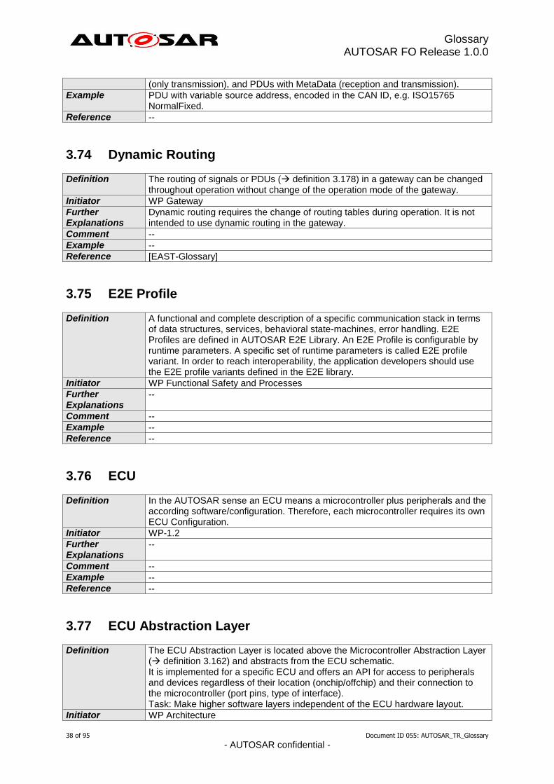
Glossary AUTOSAR FO Release 1.0.0
38 of 95 Document ID 055: AUTOSAR_TR_Glossary
- AUTOSAR confidential -
(only transmission), and PDUs with MetaData (reception and transmission).
Example PDU with variable source address, encoded in the CAN ID, e.g. ISO15765 NormalFixed.
Reference --
3.74 Dynamic Routing
Definition The routing of signals or PDUs ( definition 3.178) in a gateway can be changed throughout operation without change of the operation mode of the gateway.
Initiator WP Gateway
Further Explanations
Dynamic routing requires the change of routing tables during operation. It is not intended to use dynamic routing in the gateway.
Comment --
Example --
Reference [EAST-Glossary]
3.75 E2E Profile
Definition A functional and complete description of a specific communication stack in terms of data structures, services, behavioral state-machines, error handling. E2E Profiles are defined in AUTOSAR E2E Library. An E2E Profile is configurable by runtime parameters. A specific set of runtime parameters is called E2E profile variant. In order to reach interoperability, the application developers should use the E2E profile variants defined in the E2E library.
Initiator WP Functional Safety and Processes
Further Explanations
--
Comment --
Example --
Reference --
3.76 ECU
Definition
In the AUTOSAR sense an ECU means a microcontroller plus peripherals and the according software/configuration. Therefore, each microcontroller requires its own ECU Configuration.
Initiator WP-1.2
Further Explanations
--
Comment --
Example --
Reference --
3.77 ECU Abstraction Layer
Definition
The ECU Abstraction Layer is located above the Microcontroller Abstraction Layer ( definition 3.162) and abstracts from the ECU schematic. It is implemented for a specific ECU and offers an API for access to peripherals and devices regardless of their location (onchip/offchip) and their connection to the microcontroller (port pins, type of interface). Task: Make higher software layers independent of the ECU hardware layout.
Initiator WP Architecture
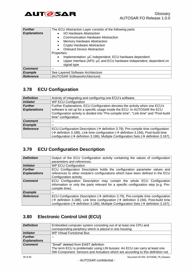
Glossary AUTOSAR FO Release 1.0.0
39 of 95 Document ID 055: AUTOSAR_TR_Glossary
- AUTOSAR confidential -
Further Explanations
The ECU Abstraction Layer consists of the following parts:
I/O Hardware Abstraction
Communication Hardware Abstraction
Memory Hardware Abstraction
Crypto Hardware Abstraction
Onboard Device Abstraction Properties:
Implementation: µC independent, ECU hardware dependent
Upper Interface (API): µC and ECU hardware independent, dependent on signal type
Comment --
Example See Layered Software Architecture
Reference [AUTOSAR SoftwareArchitecture]
3.78 ECU Configuration
Definition Activity of integrating and configuring one ECU’s software.
Initiator WP ECU Configuration
Further Explanations
Further Explanations: ECU Configuration denotes the activity when one ECU's software is set up for a specific usage inside the ECU. In AUTOSAR the ECU Configuration activity is divided into "Pre-compile time", "Link time" and "Post-build time" configuration.
Comment --
Example --
Reference ECU Configuration Description ( definition 3.79), Pre-compile time configuration ( definition 3.188), Link time configuration ( definition 3.156), Post-build time configuration ( definition 3.186), Multiple Configuration Sets ( definition 3.167).
3.79 ECU Configuration Description
Definition Output of the ECU Configuration activity containing the values of configuration parameters and references.
Initiator WP ECU Configuration
Further Explanations
ECU Configuration Description holds the configuration parameter values and references to other module's configurations which have been defined in the ECU Configuration activity.
Comment ECU Configuration Description may contain the whole ECU Configuration information or only the parts relevant for a specific configuration step (e.g. Pre-compile time).
Example --
Reference ECU Configuration Description ( definition 3.79), Pre-compile time configuration ( definition 3.188), Link time configuration ( definition 3.156), Post-build time configuration ( definition 3.186), Multiple Configuration Sets ( definition 3.167).
3.80 Electronic Control Unit (ECU)
Definition Embedded computer system consisting out of at least one CPU and corresponding periphery which is placed in one housing.
Initiator WP Virtual Functional Bus
Further Explanations
--
Comment “Small” deleted from EAST definition The term ECU is problematic using LIN busses: An ECU can carry at least one SW-Component. Sensors and Actuators which are according to this definition not
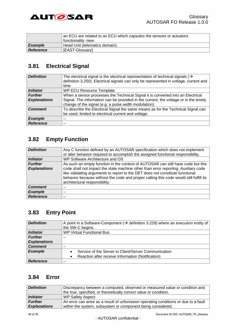
Glossary AUTOSAR FO Release 1.0.0
40 of 95 Document ID 055: AUTOSAR_TR_Glossary
- AUTOSAR confidential -
an ECU are related to an ECU which capsules the sensors or actuators functionality -new
Example Head Unit (telematics domain).
Reference [EAST-Glossary]
3.81 Electrical Signal
Definition The electrical signal is the electrical representation of technical signals ( definition 3.250). Electrical signals can only be represented in voltage, current and time
Initiator WP ECU Resource Template
Further Explanations
When a sensor processes the Technical Signal it is converted into an Electrical Signal. The information can be provided in the current, the voltage or in the timely change of the signal (e.g. a pulse width modulation).
Comment To describe the Electrical Signal the same means as for the Technical Signal can be used, limited to electrical current and voltage.
Example --
Reference --
3.82 Empty Function
Definition Any C function defined by an AUTOSAR specification which does not implement or alter behavior required to accomplish the assigned functional responsibility.
Initiator WP Software Architecture and OS
Further Explanations
As such an empty function in the context of AUTOSAR can still have code but this code shall not impact the state machine other than error reporting. Auxiliary code like validating arguments to report to the DET does not constitute functional behavior because without the code and proper calling this code would still fulfill its architectural responsibility.
Comment --
Example --
Reference --
3.83 Entry Point
Definition A point in a Software-Component ( definition 3.229) where an execution entity of the SW-C begins.
Initiator WP Virtual Functional Bus
Further Explanations
--
Comment --
Example Service of the Server in Client/Server Communication
Reaction after receive Information (Notification)
Reference --
3.84 Error
Definition Discrepancy between a computed, observed or measured value or condition and the true, specified, or theoretically correct value or condition.
Initiator WP Safety Aspect
Further Explanations
An error can arise as a result of unforeseen operating conditions or due to a fault within the system, subsystem or component being considered.
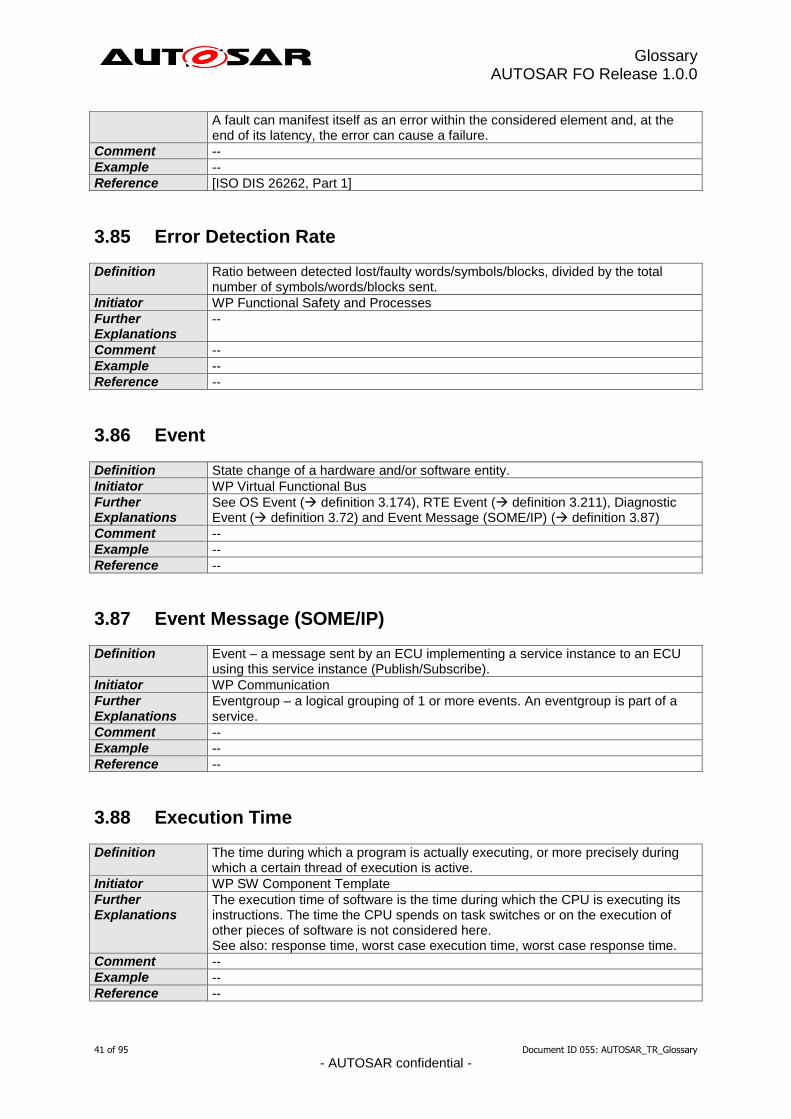
Glossary AUTOSAR FO Release 1.0.0
41 of 95 Document ID 055: AUTOSAR_TR_Glossary
- AUTOSAR confidential -
A fault can manifest itself as an error within the considered element and, at the end of its latency, the error can cause a failure.
Comment --
Example --
Reference [ISO DIS 26262, Part 1]
3.85 Error Detection Rate
Definition Ratio between detected lost/faulty words/symbols/blocks, divided by the total number of symbols/words/blocks sent.
Initiator WP Functional Safety and Processes
Further Explanations
--
Comment --
Example --
Reference --
3.86 Event
Definition State change of a hardware and/or software entity.
Initiator WP Virtual Functional Bus
Further Explanations
See OS Event ( definition 3.174), RTE Event ( definition 3.211), Diagnostic Event ( definition 3.72) and Event Message (SOME/IP) ( definition 3.87)
Comment --
Example --
Reference --
3.87 Event Message (SOME/IP)
Definition Event – a message sent by an ECU implementing a service instance to an ECU using this service instance (Publish/Subscribe).
Initiator WP Communication
Further Explanations
Eventgroup – a logical grouping of 1 or more events. An eventgroup is part of a service.
Comment --
Example --
Reference --
3.88 Execution Time
Definition The time during which a program is actually executing, or more precisely during which a certain thread of execution is active.
Initiator WP SW Component Template
Further Explanations
The execution time of software is the time during which the CPU is executing its instructions. The time the CPU spends on task switches or on the execution of other pieces of software is not considered here. See also: response time, worst case execution time, worst case response time.
Comment --
Example --
Reference --
Glossary AUTOSAR FO Release 1.0.0
42 of 95 Document ID 055: AUTOSAR_TR_Glossary
- AUTOSAR confidential -
3.89 Exit Point
Definition A point in a Software-Component ( definition 3.229) where an execution entity of the SW-C ends.
Initiator WP Virtual Functional Bus
Further Explanations
--
Comment --
Example Return point.
Reference --
3.90 Fail-degraded
Definition Property of a system or functional unit. Describes the ability of a system to continue with intended degraded operation at its output interfaces despite the presence of hardware or software faults.
Initiator WP Safety Aspect
Further Explanations
--
Comment 1. Safety means are not regarded as a part of the normal functionality respectively operation.
2. Also known as: Fail-reduced, Fail-soft
Example “Limp home” functionality for ECU (reduce torque to assure an arrival at home or service station)
Reference --
3.91 Fail-operational
Definition Property of a system or functional unit. Describes the ability of a system or functional unit to continue normal operation at its output interfaces despite the presence of hardware or software faults.
Initiator WP Safety Aspect
Further Explanations
--
Comment 1. Typically, a fail-operational system or functional unit has no safe state. 2. Safety means are not regarded as a part of the normal functionality
respectively operation.
Example Braking system
Reference --
3.92 Fail-safe
Definition Property of a system or functional unit. In case of a fault the system or functional unit transits to a safe state.
Initiator WP Safety Aspect
Further Explanations
--
Comment --
Example --
Reference --
Glossary AUTOSAR FO Release 1.0.0
43 of 95 Document ID 055: AUTOSAR_TR_Glossary
- AUTOSAR confidential -
3.93 Fail-silent
Definition Property of a system or functional unit. In case of a fault the output interfaces are disabled in a way that no further outputs are made.
Initiator WP Safety Aspect
Further Explanations
Fail-silent is a special case of the fail-safe property.
Comment --
Example The fail-silent property can be used to avoid that “babbling idiots” disturb the overall communication.
Reference --
3.94 Failure
Definition Termination of the ability of an element or an item to perform a function as required.
Initiator WP Safety Aspect
Further Explanations
Termination is a reduction in, or loss of, ability of an element or an item to perform a function as required. There is a difference between “to perform a function as required” (stronger definition, use-oriented) and ”to perform a function as specified”, so a failure can result from an incorrect specification.
Comment --
Example --
Reference [ISO DIS 26262, Part 1]
3.95 Failure Rate
Definition Frequency of occurrence of an error measured within a specific period. It is usually expressed in [1e9 * h
-¹] = [FIT], which means how many faults happen
within 1.000.000.000 hours. Error rates can be determined by physical/mathematical models and by tracking of failures of already produced units.
Initiator WP Functional Safety and Processes
Further Explanations
--
Comment --
Example --
Reference --
3.96 Fault
Definition Abnormal condition that can cause an element or an item to fail.
Initiator WP Safety Aspect
Further Explanations
In the context of AUTOSAR an element is e.g. a BSW Module ( definition 3.33), a SW-C ( definition 3.229) or the CPU.
Comment --
Example --
Reference [ISO DIS 26262, Part 1]
Glossary AUTOSAR FO Release 1.0.0
44 of 95 Document ID 055: AUTOSAR_TR_Glossary
- AUTOSAR confidential -
3.97 Fault Detection
Definition The action of monitoring errors and setting fault states to specific values is called fault detection.
Initiator WP Virtual Functional Bus
Further Explanations
The different states are called “not detected”/ “present”/ ”intermittent or maturing”/… The names of the fault states are following the ISO/SAE norms; however there is a coordination step in between the states of the DTCs (Diagnostic Trouble Code see definition in ISO 15765/ ISO14229) and the states of the faults. The SW-C’s Fault Detection is executed decentralized, e.g. each SW-C sets the state of a fault according to the defined fault qualification (SW-C Template). Therefore the Fault Detection is implemented in the SW-C (SW-C could be either Application SW Component or Basic SW Component). There are exceptions; these will be pointed out individually for each fault. The SW-C’s developer will define the conditions (=fault qualification), when these conditions are fulfilled the SW-C notifies a fault to the Diagnostic Memory Management.
Comment --
Example --
Reference [ISO 15765], [ISO14229] [AUTOSAR Specification of Virtual Functional Bus]
3.98 Fault Reaction
Definition In case of a Failure of a SW-C there is a specific action to be carried out. This action is called “Fault Reaction”.
Initiator WP Virtual Functional Bus
Further Explanations
--
Comment --
Example Fault Reactions can be implemented decentralized in the SW-C. There might also be the need of coordinating the fault reactions since there are reactions excluding each other. This will be done by a central fault reaction manager.
Reference --
3.99 Fault Tolerance
Definition Property of a system or functional unit. In case of n faults the system or functional unit continues with full functionality (n>0).
Initiator WP Safety Aspect
Further Explanations
--
Comment --
Example --
Reference --
3.100 Feature
Definition A Feature is a notable characteristic of a system.
Initiator WP Authoring Tools
Further AUTOSAR defines and interacts with many entities where the term Feature can
Glossary AUTOSAR FO Release 1.0.0
45 of 95 Document ID 055: AUTOSAR_TR_Glossary
- AUTOSAR confidential -
Explanations be applied (e.g. the AUTOSAR standard itself, its implementations, ECUs built with AUTOSAR, AUTOSAR Authoring Tools, AUTOSAR Feature Model). For each usage the term Feature may be used in a refined way - which is then defined for that specific usage (e.g. [TPS_FeatureModelExchangeFormat]).
Comment --
Example CAN FD support, Automatic windshield wiper, Editing of the FlexRay schedule
Reference [EAST-Glossary], [TPS_FeatureModelExchangeFormat]
3.101 First party
Definition An organization that provides automotive products, which are subject to AUTOSAR conformance testing.
Initiator WP Exploitation
Further Explanations
--
Comment --
Example --
Reference --
3.102 Flag
Definition A piece of data that can take on one of two values indicating whether a logical condition is true or false.
Initiator WP Virtual Functional Bus
Further Explanations
--
Comment --
Example Notification flag
Reference --
3.103 FlexRay Base Cycle
Definition One operand of the equation used to calculate the Cycle Numbers ( definition 3.109) of the FlexRay Cells ( definition 3.105) being used for periodic transmission of FlexRay Frames ( definition 3.112) in a given FlexRay Slot ( definition 3.121). Equation:
Cycle Number = (B + n * 2R)mod64
Where:
Base Cycle B = 0 … 63
Cycle Repetition 2R = 2
0 … 2
6 = 1, 2, 4, 8, … 64
Variable n = 0 … 64
B < 2R
(See also graphic in FlexRay L-SDU-Identifier definition 3.116)
Initiator WP FlexRay
Further Explanations
--
Comment Synonym: “Cycle Offset”, “Cycle Counter Offset”
Example --
Reference --

Glossary AUTOSAR FO Release 1.0.0
46 of 95 Document ID 055: AUTOSAR_TR_Glossary
- AUTOSAR confidential -
3.104 FlexRay Bus
Definition A communication system topology in which Nodes ( definition 3.119) are directly connected to a single, common communication media (as opposed to connection through Stars ( definition 3.124), gateways, etc.). The term “bus” is also used to refer to the media itself.
Initiator WP FlexRay
Further Explanations
The term “FlexRay Bus” is not to be confused with the term “FlexRay Cluster” ( definition 3.107) or “FlexRay Network” ( definition 3.118).
Comment Synonym: “FlexRay Communication Bus”
Example --
Reference [FR_PROTOCOL]
3.105 FlexRay Cell
Definition One element in a FlexRay Matrix ( definition 3.117) unequivocally defined by a combination of exactly one FlexRay Slot (or FlexRay Slot Number) ( definition 3.121) and exactly one FlexRay Cycle (or FlexRay Cycle Number) ( definition 3.108). In other words: a FlexRay Cell is defined by the tuple <Slot Number, Cycle Number>. Each FlexRay Cell represents one (possible) transmission time interval for at most one FlexRay Frame ( definition 3.112). If a FlexRay Network ( definition 3.118) consists of two Channels ( definition 3.106), there is one FlexRay Matrix per Channel , so there are also two FlexRay Cells defined by the same tuple <Slot Number, Cycle Number>, one for “Channel A” and one for “Channel B”.
Initiator WP FlexRay
Further Explanations
In order to achieve periodic transmission of FlexRay Frames in a given FlexRay Slot, the Cycle Numbers of the FlexRay Cells being used for transmission have to fulfill the following equation: Equation:
Cycle Number = (B + n * 2R)mod64
Where:
Base Cycle B = 0 … 63
Cycle Repetition 2R = 2
0 … 2
6 = 1, 2, 4, 8, … 64
Variable n = 0 … 64
B < 2R
Comment Synonym: “FlexRay Matrix Cell”
Example --
Reference --
3.106 FlexRay Channel
Definition The inter-Node ( definition 3.119) connection through which signals are conveyed for the purpose of communication. The communication channel abstracts both the network topology, i.e., Bus ( definition 3.104) or Star ( definition 3.124), as well as the physical transmission medium, i.e. electrical or optical.
Initiator WP FlexRay
Further Explanations
According to the FlexRay Protocol Specification, the two possible Channels of a FlexRay Network ( definition 3.118) are named “Channel A” and “Channel B”.
Comment Synonym: “FlexRay Communication Channel”
Example --
Reference [FR_PROTOCOL]
Glossary AUTOSAR FO Release 1.0.0
47 of 95 Document ID 055: AUTOSAR_TR_Glossary
- AUTOSAR confidential -
3.107 FlexRay Cluster
Definition A communication system of multiple Nodes ( definition 3.119) connected directly (Bus topology) or by Star Couplers (Star topology) ( definition 3.124) via a Communication Network consisting of at least one Communication Channel.
Initiator WP FlexRay
Further Explanations
The term “FlexRay Cluster” is not to be confused with the term “FlexRay Bus” ( definition 3.104) which describes a communication system topology. A FlexRay Cluster consists of a FlexRay Network ( definition 3.118) and several FlexRay Nodes.
Comment --
Example --
Reference [FR_PROTOCOL]
3.108 FlexRay Cycle
Definition One complete instance of the communication structure that is periodically repeated to comprise the media access method of the FlexRay system. The Communication Cycle consists of a Static Segment, an optional Dynamic Segment, an optional Symbol Window, and a Network Idle Time. The FlexRay Cycles are unequivocally numbered by the FlexRay Cycle Number ( definition 3.109) ranging from 0 to 63. Even if a FlexRay Network ( definition 3.118) consists of two Channels, the FlexRay Cycle is always a common quantity of both Channels, irrespective of the data transmission schedule possibly being different for the two Channels.
Initiator WP FlexRay
Further Explanations
--
Comment Synonym: “FlexRay Communication Cycle”
Example --
Reference [FR_PROTOCOL]
3.109 FlexRay Cycle Number
Definition An unequivocal number of a FlexRay Cycle ( definition 3.108), ranging from 0 to 63.
Initiator WP FlexRay
Further Explanations
--
Comment Synonym: “FlexRay Communication Cycle Number”
Example --
Reference [FR_PROTOCOL]
3.110 FlexRay Cycle Offset
Definition See definition of Base Cycle ( definition 3.103).
Initiator WP FlexRay
Further Explanations
--
Comment This term is mentioned here to simplify finding it via this document’s table of contents.
Glossary AUTOSAR FO Release 1.0.0
48 of 95 Document ID 055: AUTOSAR_TR_Glossary
- AUTOSAR confidential -
Synonym: “Cycle Counter Offset”, “Base Cycle”
Example --
Reference --
3.111 FlexRay Cycle Repetition
Definition One operand of the equation used to calculate the Cycle Numbers ( definition 3.109) of the FlexRay Cells ( definition 3.105) being used for periodic transmission of FlexRay Frames ( definition 3.112) in a given FlexRay Slot ( definition 3.121). Equation:
Cycle Number = (B + n * 2R)mod64
Where:
Base Cycle B = 0 … 63
Cycle Repetition 2R = 2
0 … 2
6 = 1, 2, 4, 8, … 64
Variable n = 0 … 64
B < 2R
(See also graphic in FlexRay L-SDU-Identifier definition 3.116)
Initiator WP FlexRay
Further Explanations
--
Comment Synonym: “Cycle Counter Repetition”
Example --
Reference --
3.112 FlexRay Frame
Definition A structure used by the communication system to exchange information within the system. A FlexRay Frame consists of a header segment, a payload segment and a trailer segment. The payload segment is used to convey application data.
Initiator WP FlexRay
Further Explanations
A FlexRay Frame is a “data package” that may be transmitted within a FlexRay Cell ( definition 3.105).
Comment Synonym: “FlexRay L-PDU”
Example --
Reference [FR_PROTOCOL]
3.113 FlexRay Global Time
Definition A tuple consisting of one specific value of the FlexRay Cycle Counter and one specific value of the FlexRay Cycle Time in Macroticks.
Initiator WP FlexRay
Further Explanations
--
Comment --
Example --
Reference [FR_PROTOCOL]
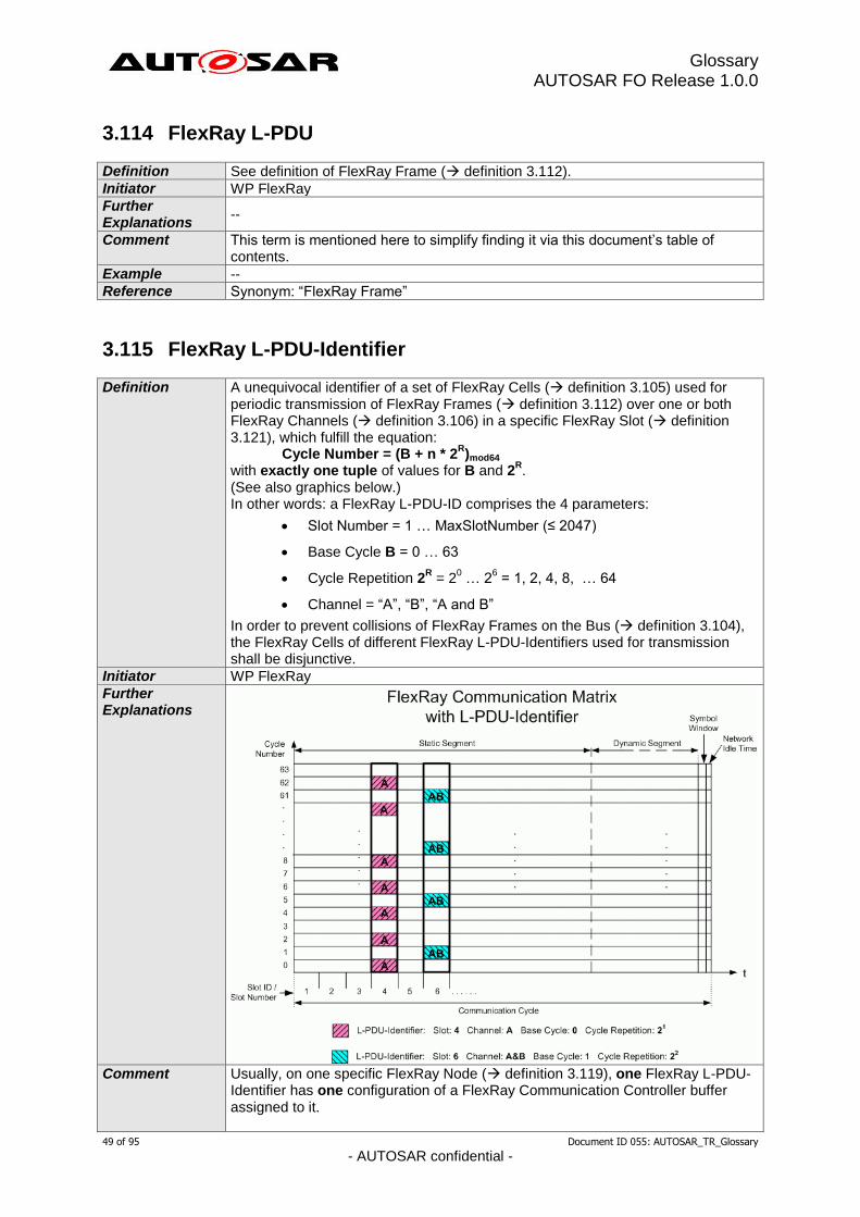
Glossary AUTOSAR FO Release 1.0.0
49 of 95 Document ID 055: AUTOSAR_TR_Glossary
- AUTOSAR confidential -
3.114 FlexRay L-PDU
Definition See definition of FlexRay Frame ( definition 3.112).
Initiator WP FlexRay
Further Explanations
--
Comment This term is mentioned here to simplify finding it via this document’s table of contents.
Example --
Reference Synonym: “FlexRay Frame”
3.115 FlexRay L-PDU-Identifier
Definition A unequivocal identifier of a set of FlexRay Cells ( definition 3.105) used for periodic transmission of FlexRay Frames ( definition 3.112) over one or both FlexRay Channels ( definition 3.106) in a specific FlexRay Slot ( definition 3.121), which fulfill the equation:
Cycle Number = (B + n * 2R)mod64
with exactly one tuple of values for B and 2R.
(See also graphics below.) In other words: a FlexRay L-PDU-ID comprises the 4 parameters:
Slot Number = 1 … MaxSlotNumber (≤ 2047)
Base Cycle B = 0 … 63
Cycle Repetition 2R = 2
0 … 2
6 = 1, 2, 4, 8, … 64
Channel = “A”, “B”, “A and B”
In order to prevent collisions of FlexRay Frames on the Bus ( definition 3.104), the FlexRay Cells of different FlexRay L-PDU-Identifiers used for transmission shall be disjunctive.
Initiator WP FlexRay
Further Explanations
Comment Usually, on one specific FlexRay Node ( definition 3.119), one FlexRay L-PDU-
Identifier has one configuration of a FlexRay Communication Controller buffer assigned to it.
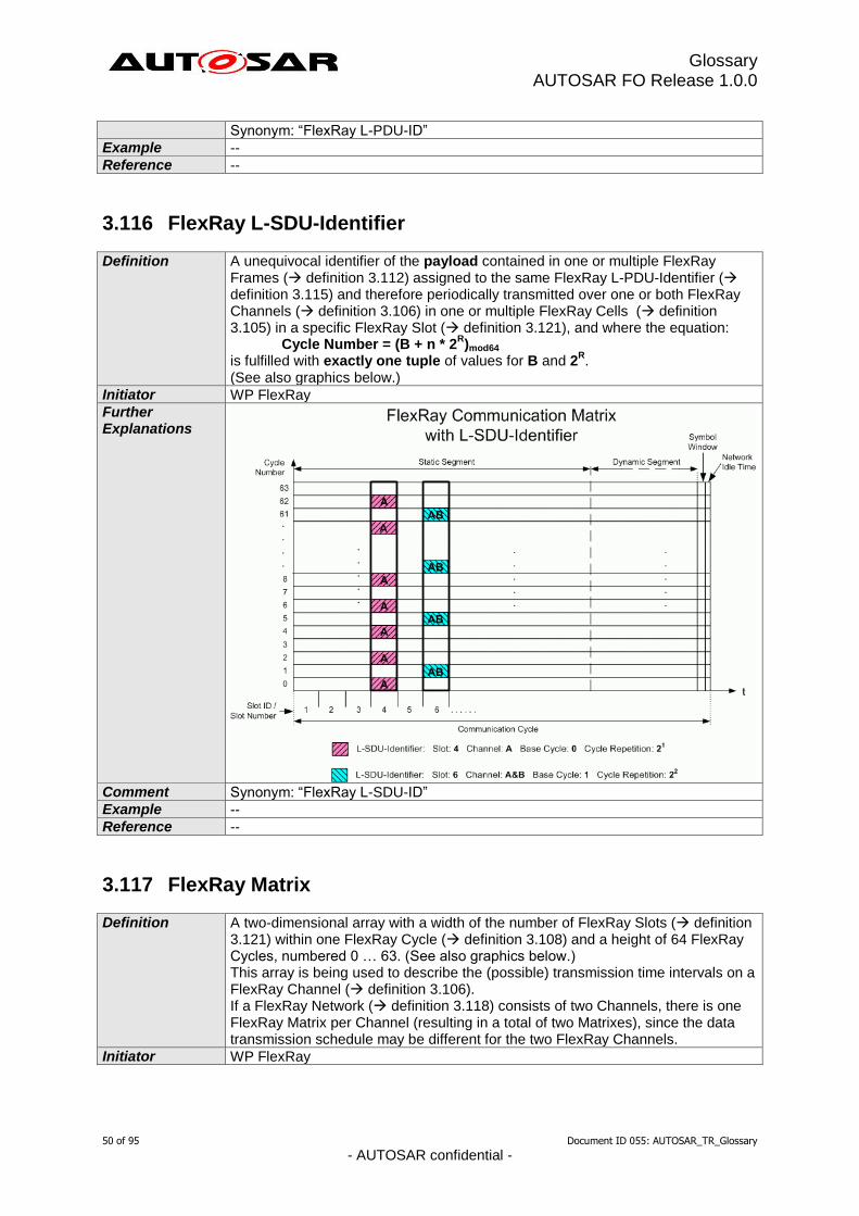
Glossary AUTOSAR FO Release 1.0.0
50 of 95 Document ID 055: AUTOSAR_TR_Glossary
- AUTOSAR confidential -
Synonym: “FlexRay L-PDU-ID”
Example --
Reference --
3.116 FlexRay L-SDU-Identifier
Definition A unequivocal identifier of the payload contained in one or multiple FlexRay Frames ( definition 3.112) assigned to the same FlexRay L-PDU-Identifier ( definition 3.115) and therefore periodically transmitted over one or both FlexRay Channels ( definition 3.106) in one or multiple FlexRay Cells ( definition 3.105) in a specific FlexRay Slot ( definition 3.121), and where the equation:
Cycle Number = (B + n * 2R)mod64
is fulfilled with exactly one tuple of values for B and 2R.
(See also graphics below.)
Initiator WP FlexRay
Further Explanations
Comment Synonym: “FlexRay L-SDU-ID”
Example --
Reference --
3.117 FlexRay Matrix
Definition A two-dimensional array with a width of the number of FlexRay Slots ( definition 3.121) within one FlexRay Cycle ( definition 3.108) and a height of 64 FlexRay Cycles, numbered 0 … 63. (See also graphics below.) This array is being used to describe the (possible) transmission time intervals on a FlexRay Channel ( definition 3.106). If a FlexRay Network ( definition 3.118) consists of two Channels, there is one FlexRay Matrix per Channel (resulting in a total of two Matrixes), since the data transmission schedule may be different for the two FlexRay Channels.
Initiator WP FlexRay

Glossary AUTOSAR FO Release 1.0.0
51 of 95 Document ID 055: AUTOSAR_TR_Glossary
- AUTOSAR confidential -
Further Explanations
Comment Synonym: “FlexRay Communication Matrix”
Example --
Reference [FR_PROTOCOL]
3.118 FlexRay Network
Definition The combination of the (up to two) FlexRay Communication Channels that connect the FlexRay Nodes ( definition 3.119) of a FlexRay Cluster ( definition 3.107).
Initiator WP FlexRay
Further Explanations
The term “FlexRay Network” is not to be confused with the term “FlexRay Cluster” or “FlexRay Bus” ( definition 3.104).
Comment Synonym: “FlexRay Communication Network”
Example --
Reference [FR_PROTOCOL]
3.119 FlexRay Node
Definition A logical entity connected to the FlexRay Network ( definition 3.118) that is capable of sending and/or receiving frames.
Initiator WP FlexRay
Further Explanations
--
Comment --
Example --
Reference [FR_PROTOCOL]
3.120 FlexRay Physical Communication Link
Definition An inter-Node ( definition 3.119) connection through which signals are conveyed for the purpose of communication. All Nodes connected to a given Physical
Glossary AUTOSAR FO Release 1.0.0
52 of 95 Document ID 055: AUTOSAR_TR_Glossary
- AUTOSAR confidential -
Communication Link share the same electrical or optical signals (i.e., they are not connected through repeaters, Stars ( definition 3.124), gateways, etc.). Examples of a Physical Communication Link include a Bus ( definition 3.104) Network or a point-to-point connection between a Node and a Star. A Communication Channel may be constructed by combining one or more Physical Communication Links together using Stars.
Initiator WP FlexRay
Further Explanations
--
Comment --
Example --
Reference [FR_PROTOCOL]
3.121 FlexRay Slot
Definition An interval of time during which access to a Communication Channel is granted exclusively (at least in the static segment) to a specific Node ( definition 3.119) for the transmission of a Frame ( definition 3.112) with a frame ID corresponding to the Slot Number ( definition 3.123) of that Slot. FlexRay distinguishes between Static Communication Slots and Dynamic Communication Slots. The FlexRay Slots are unequivocally numbered by the FlexRay Slot Number ranging from 1 to a configurable maximum number ≤ 2047. If a FlexRay Network ( definition 3.118) consists of two Channels ( definition 3.106), the Static Slots of “Channel A” and the Static Slots of “Channel B” occur concurrently, since all Static FlexRay Slots have the same length irrespective of the data transmission schedule. However, the Dynamic Slots of “Channel A” are independent from the Dynamic Slots of “Channel B”, since the data transmission schedule may be different for the two FlexRay Channels.
Initiator WP FlexRay
Further Explanations
In the dynamic segment, Slot Multiplexing between multiple Nodes is allowed. In the static segment each Slot ( definition 3.121) on a Channel is owned by exactly one Node (i.e., Slot Multiplexing is not allowed in the static segment). Slot Multiplexing (i.e., different FlexRay Nodes owning a Slot in different Cycles ( definition3.108) for data transmission) is allowed in the dynamic segment, and it is up to the application to ensure that in any given Cycle no two Nodes transmit in the same Slot on the same Channel.
Comment Synonym: “FlexRay Communication Slot”
Example --
Reference [FR_PROTOCOL]
3.122 FlexRay Slot Multiplexing
Definition A method used to fill a FlexRay Slot ( definition 3.121) on a Channel ( definition 3.106) more efficiently by alternating the Frames being sent in this Slot from Cycle ( definition 3.108) to Cycle. In order to achieve periodic transmission of FlexRay Frames ( definition 3.112) in a given FlexRay Slot, the Cycle Numbers ( definition 3.109) of the FlexRay Cells ( definition 3.105) being used for transmission have to fulfill the equation:
Cycle Number = (B + n * 2R)mod64
Where:
Base Cycle B = 0 … 63
Cycle Repetition 2R = 2
0 … 2
6 = 1, 2, 4, 8, … 64
Variable n = 0 … 64
B < 2R
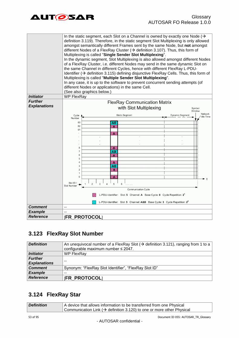
Glossary AUTOSAR FO Release 1.0.0
53 of 95 Document ID 055: AUTOSAR_TR_Glossary
- AUTOSAR confidential -
In the static segment, each Slot on a Channel is owned by exactly one Node ( definition 3.119). Therefore, in the static segment Slot Multiplexing is only allowed amongst semantically different Frames sent by the same Node, but not amongst different Nodes of a FlexRay Cluster ( definition 3.107). Thus, this form of Multiplexing is called "Single Sender Slot Multiplexing". In the dynamic segment, Slot Multiplexing is also allowed amongst different Nodes of a FlexRay Cluster, i.e. different Nodes may send in the same dynamic Slot on the same Channel in different Cycles, hence with different FlexRay L-PDU-Identifier ( definition 3.115) defining disjunctive FlexRay Cells. Thus, this form of Multiplexing is called "Multiple Sender Slot Multiplexing". In any case, it is up to the software to prevent concurrent sending attempts (of different Nodes or applications) in the same Cell. (See also graphics below.)
Initiator WP FlexRay
Further Explanations
Comment --
Example --
Reference [FR_PROTOCOL]
3.123 FlexRay Slot Number
Definition An unequivocal number of a FlexRay Slot ( definition 3.121), ranging from 1 to a configurable maximum number ≤ 2047.
Initiator WP FlexRay
Further Explanations
--
Comment Synonym: “FlexRay Slot Identifier”, “FlexRay Slot ID”
Example --
Reference [FR_PROTOCOL]
3.124 FlexRay Star
Definition A device that allows information to be transferred from one Physical Communication Link ( definition 3.120) to one or more other Physical
Glossary AUTOSAR FO Release 1.0.0
54 of 95 Document ID 055: AUTOSAR_TR_Glossary
- AUTOSAR confidential -
Communication Links. A star duplicates information present on one of its links to the other links connected to the star. A star can be either passive or active.
Initiator WP FlexRay
Further Explanations
--
Comment Synonym: “Star”, “Star Couplers”
Example --
Reference [FR_PROTOCOL]
3.125 Frame
Definition Data unit according to the data link protocol specifying the arrangement and meaning of bits or bit fields in the sequence of transfer across the transfer medium .
Initiator WP Architecture
Further Explanations
--
Comment --
Example A CAN frame consists of up to 8 bytes of payload data and additional protocol specific bits / bit fields (e.g. CAN-Identifier).
Reference [ISO 17356, Glossary]
3.126 Frame PDU
Definition A PDU that fits into 1 frame instance. e.g. it does not need to be fragmented across more than 1 frame for transmission over a network.
Initiator WP Architecture
Further Explanations
--
Comment --
Example --
Reference --
3.127 Function
Definition 1. A task, action or activity that must be accomplished to achieve a desired outcome.
2. A part of programming code that is invoked by other parts of the program to fulfill a desired purpose.
3. In mathematics, a function is an association between two sets of values in which each element of one set has one assigned element in the other set so that any element selected becomes the independent variable and its associated element is the dependent variable.
Initiator WP Virtual Functional Bus
Further Explanations
--
Comment Due to the different meanings in texts using the term application the appropriate meaning should be explained in detail or referenced.
Example 2. C-Code Function 3. Y=f(x)
Reference [IEEE12331], [EAST-Glossary]
Glossary AUTOSAR FO Release 1.0.0
55 of 95 Document ID 055: AUTOSAR_TR_Glossary
- AUTOSAR confidential -
3.128 Functional Network
Definition A logical structure of interconnections between defined functional parts of features ( definition 3.100).
Initiator WP Virtual Functional Bus
Further Explanations
--
Comment --
Example --
Reference --
3.129 Functional Unit
Definition An entity of software or hardware, or both, capable of accomplishing a specified purpose.
Initiator WP Virtual Functional Bus
Further Explanations
--
Comment --
Example ECU, Software Component, ...
Reference [ISO 2382-1]
3.130 Functionality
Definition Functionality comprises User-visible and User-non-visible functional aspects of a system.
Initiator WP Virtual Functional Bus
Further Explanations
--
Comment EAST glossary not applicable, due to use of function.
Example Functionality of a communication system is a user-non-visible aspect.
Reference --
3.131 Gateway
Definition A gateway is functionality within an ECU that performs a frame or signal mapping function between two communication systems. Communication system in this context means e.g. a CAN system or one channel of a FlexRay system.
Initiator WP System Constraint Template
Further Explanations
--
Comment --
Example --
Reference Gateway ECU 0
3.132 Gateway ECU
Definition A gateway ECU is an ECU ( definition 3.80) that is connected to two or more communication channels, and performs gateway functionality.
Initiator WP System Constraint Template
Further Explanations
--
Glossary AUTOSAR FO Release 1.0.0
56 of 95 Document ID 055: AUTOSAR_TR_Glossary
- AUTOSAR confidential -
Comment --
Example --
Reference Gateway 3.131
3.133 Hardware Connection
Definition HW Connections are used to describe the connection of HW elements ( definition 3.134) among each other. It defines/characterizes the interrelationship among HW Elements (for abstract modelling). The HW Ports ( definition 3.136) of the HW Elements serve as connection points for this purpose.
Initiator WP ECU Resource Template
Further Explanations
In AUTOSAR are 2 kinds of HW Connections defined: Assembly HW Connection Delegation HW Connection
Comment --
Example --
Reference [AUTOSAR Specfication of ECU Resource Template]
3.134 Hardware Element
Definition The HW Element is the main describing element of an ECU ( definition 3.80). It provides HW ports ( definition 3.136) for being interconnected among each others. A generic HW Element specifies definitions valid for all specific HW Elements.
Initiator WP ECU Resource Template
Further Explanations
A HW Element is the piece or a part of the piece to be described with the ECU Resource Template. It uses other elements as primitive: This means HW elements can be nested (trough HW Containers, a hierarchical structur of HW Elements). At the lowest level a HW Element only uses promitives
Comment --
Example --
Reference [AUTOSAR Specification of ECU Resource Template]
3.135 Hardware Interrupt
Definition Interrupt triggered by HW event
Initiator WP Virtual Functional Bus
Further Explanations
2 sorts of HW events
Processor-intern: events as for example division by zero, arithmetical overflow, non-implemented instruction
Processor-extern: events as for example response of peripheral device (e.g. PWM), memory error, timer
Comment --
Example --
Reference Translation/Adaptation from [VDI Lexikon]
3.136 Hardware Port
Definition The HW port exposes functionality to the exterior of the HW element ( definition 3.134). HW elements can be connected via HW Connections ( definition 3.133). It defines a connection Endpoint for the HW Element.
Initiator WG System Team
Glossary AUTOSAR FO Release 1.0.0
57 of 95 Document ID 055: AUTOSAR_TR_Glossary
- AUTOSAR confidential -
Further Explanations
HW elements provide HW ports for being interconnected among each others. Each HW port has a name which is unique within the HW element it is located in.
Comment --
Example --
Reference [AUTOSAR Specification of ECU Resource Template]
3.137 Hook
Definition An intervention point within ECU software for the exchange of data.
Initiator WP VFB and RTE
Further Explanations
--
Comment --
Example Hooks used to read ECU variables and/ or overwrite ECU variables with values generated by RP ( definition 3.195) algorithm.
Reference --
3.138 I-PDU
Definition Interaction Layer Protocol Data Unit Collection of messages for transfer between nodes in a network. At the sending node the Interaction Layer (IL) is responsible for packing messages into an I-PDU and then sending it to the Data Link Layer (DLL) for transmission. At the receiving node the DLL passes each I-PDU to the IL which then unpacks the messages sending their contents to the application.
Initiator WP Architecture
Further Explanations
--
Comment --
Example ISO 17356-4 specifies an Interaction Layer and works on I-PDUs
Reference [ISO 17356, Glossary]
3.139 ICC1 (Implementation Conformance Class 1)
Definition An ICC1 cluster offers a software-component interface (SW-CI) ( definition 3.230) and/ or an AUTOSAR network interface (NWI) ( definition 3.169). The SW-CI and NWI of an ICC1 cluster provide the functional behavior as specified in the AUTOSAR specifications on ICC3 level.
Initiator WP Conformance Test Specification
Further Explanations
In an ICC1 cluster the basic software is regarded as a black box. It allows legacy platforms to migrate to AUTOSAR: - to be integrated into an AUTOSAR network - to support SW-Cs ( definition 3.229). The features of an ICC1 cluster can be a subset of the ICC3 features (e.g. FlexRay not used). This has to be indicated in the Implementation Conformance Statement (ICS) ( definition 3.142). The functionality represented in AUTOSAR by the RTE must be a part of any ICC1 cluster that provides an SW-CI. Typically an ICC1 cluster - is not structured into Basic Software (BSW) modules (ICC3) or BSW module clusters (ICC2) - has a proprietary internal structure and might consist of legacy/proprietary or

Glossary AUTOSAR FO Release 1.0.0
58 of 95 Document ID 055: AUTOSAR_TR_Glossary
- AUTOSAR confidential -
highly optimized code. An ICC1 cluster shall provide an interface to the boot loader. ICC1 shall support SW-C compatible configuration for SW-CI and AUTOSAR Network compatible Configuration for NWI.
Comment Up to Release 4.0 the boot loader architecture is not standardized in AUTOSAR. Therefore the term ICC1 is not applicable to the boot loader architecture itself.
Example --
Reference --
3.140 ICC2 (Implementation Conformance Class 2)
Definition ICC2 clusters logically related ICC3 Basic Software (BSW) modules (2… N modules). The number of Cluster Features in an ICC2 cluster is a subset of the union of the number of features of the clustered ICC3 modules.
Initiator WP Software Architecture and OS
Further Explanations
Each ICC2 cluster presents a subset of the clustered ICC3 module’s interfaces. ICC2 cluster provides the functional behavior as specified in the AUTOSAR specifications on ICC3 level. ICC2 cluster have a proprietary internal structure and might consist of proprietary or highly optimized code. ICC2 shall support AUTOSAR ECU Configuration description as an input for the Cluster Configuration It shall be possible to combine ICC2 Clusters and ICC3 Modules in a BSW Architecture. Application interface Conformance (above RTE, software-component interface, SW-CI ( definition 3.230)) and Bus Conformance (AUTOSAR network interface, NWI ( definition 3.169)) must be testable for a BSW which contain one or more ICC2 clusters.
Comment --
Example Example of a ICC2 Cluster
ICC2 Cluster Y ( ICC3 Module A U ICC3 Module B U ICC3 Module C U ICC3 Module D )

Glossary AUTOSAR FO Release 1.0.0
59 of 95 Document ID 055: AUTOSAR_TR_Glossary
- AUTOSAR confidential -
External Interfaces relevant for ICC2 clustering, subset of ICC3 interfaces to other BSW modules or clusters. Internal Interfaces not relevant for ICC2 clustering (can be proprietary).
Reference --
3.141 ICC3 (Implementation Conformance Class 3)
Definition For ICC3 the AUTOSAR BSW consists of BSW modules as defined in the Basic Software Module List, including the RTE. ICC3 is the highest level of granularity.
Initiator WP Software Architecture and OS
Further Explanations
All Basic Software modules as defined in the BSW module list including the RTE, must comply with the defined interfaces and functionality as specified in their respective Software specification document (SWS).
Comment --
Example --
Reference --
3.142 Implementation Conformance Statement
Definition Implementation Conformance Statement (ICS) describes the actual implementation of a BSW module or a BSW cluster in terms of
(1) the actually supported values or value ranges of parameters that enable the configuration of the functionality of a module/cluster implementation and
(2) the signatures of the operations actually provided and required at the interface of a module/cluster implementation
Initiator WP Conformance Test Specification
Further Explanations
(1) An SWS of a module/cluster specifies the configurable functionality and configurable operations of all SWS-conformant module/cluster implementations
Module A
Module C
Module B
Module D
a b
c d
f h
e
g

Glossary AUTOSAR FO Release 1.0.0
60 of 95 Document ID 055: AUTOSAR_TR_Glossary
- AUTOSAR confidential -
(BSW implementations). The ICS restricts the generally configurable functionality and operations according to what a concrete module/cluster actually implements according to the specification (SWS). (2) The ICS is used to derive values of configuration parameters (CP) valid for the given implementation of a module/cluster and, e.g., to select and parameterize conformance test suites. (3) A BSW implementation can consist of variable parts, i.e., operations and functionality. A BSW implementation can be adjusted with CPs within a certain range of permitted parameter values. An ICS describes which parts a BSW implementation actually supports and to what extend. (4) For any given CP : a. The absolute range is limited by the type of the CP. b. The permitted range is limited by the SWS. c. The actual range is limited by the implementation of the BSW module or BSW cluster. A test suite or the integration of the BSW module or BSW cluster into a target platform limits the actual range to a single value.
Comment An ICS is a view on a BSW Module Description (BSWMD). An ICS can be extracted from a BSWMD.
Example (1) An ICS describes which operations a BSW module/cluster actually provides (2) The number of entries for the standard job queue of the NVRAM Manager (NvM) is defined with CP NVM_SIZE_STANDARD_JOB_QUEUE. a. The type of the CP is unit8. Thus the absolute range is 0..255. b. The SWS limits the permitted range to 1..255. c. A specific NvM implementation states to support the full range of permitted values 1..255. Tests run the specific NvM implementation with job queues of 1, 8 and 173 entries. During integration the number of queue entries is limited to 64 entries because of known application-specific usage constraints.
Reference The definition is partially based on ITU-T Recommendation X.296 [1]
3.143 Indication
Definition Service primitive defined in the ISO/OSI Reference Model (ISO 7498). With the service primitive 'indication' a service provider informs a service user about the occurrence of either an internal event or a service request issued by another service user.
Initiator WP Virtual Functional Bus
Further Explanations
An indication is e.g. a specific notification generated by the underlying layer to inform about a Message Reception Error.
Comment --
Example --
Reference --
3.144 Integration
Definition The progressive assembling of system components into the whole system.
Initiator WP Virtual Functional Bus
Further Explanations
--
Comment --
Example --
Reference [ISO 2382-20]
Glossary AUTOSAR FO Release 1.0.0
61 of 95 Document ID 055: AUTOSAR_TR_Glossary
- AUTOSAR confidential -
3.145 Integration Code
Definition Code that the Integrator needs to add to an AUTOSAR System, to adapt non-standardized functionalities. Examples are Callouts (--> definition 3.41) of the ECU State Manager and Callbacks (--> definition 3.40) of various other BSW Modules (--> definition 3.33).
Initiator WP Software Architecture and OS
Further Explanations
--
Comment --
Example --
Reference --
3.146 Interface
Definition A shared boundary between two functional units ( definition 3.129) defined by various characteristics pertaining to the functions, physical interconnections, signal exchanges, and other characteristics, as appropriate.
Initiator WP Virtual Functional Bus
Further Explanations
In AUTOSAR the interface has specific meanings: See Standardized AUTOSAR Interface ( definition 3.237) and Standardized Interface ( definition 3.239).
Comment --
Example Diagnosis Service
Reference [ISO 2382-1]
3.147 Interrupt
Definition Event that enforces the processor to change its state. This interruption causes the normal sequence of instructions to be stopped. Once an interrupt occurred, the running software entity is suspended and an interrupt service routine ( definition 0) (the one dedicated to this interrupt) is called.
Initiator WP Virtual Functional Bus
Further Explanations
Two sorts of interrupts exists: HW and SW interrupts ( definition 3.135 and definition 3.232)
Comment --
Example --
Reference Translation/Adaptation from [VDI Lexikon]
3.148 Interrupt Frames
Definition An interrupt frame is the code which handles the entering/leaving of (C written) interrupt service routines. This code is microcontroller specific and often written in assembly language. Interrupt frames are typically generated by the OS generation tool.
Initiator WP Software Architecture and OS
Further Explanations
--
Comment --
Example --
Reference [AUTOSAR_InterruptHandling_Explanation.doc]
Glossary AUTOSAR FO Release 1.0.0
62 of 95 Document ID 055: AUTOSAR_TR_Glossary
- AUTOSAR confidential -
3.149 Interrupt Handler
Definition In the case of a Category 2 interrupt, the ISR is synonymous with Interrupt Handler. In the case of Category 1 interrupt the Interrupt Handler is the function called by the hardware interrupt vector. In both cases the Interrupt handler is the user code that is normally a part of the BSW module. So the Interrupt Handler is a user level piece of code.
Initiator WP Software Architecture and OS
Further Explanations
--
Comment --
Example --
Reference [AUTOSAR_InterruptHandling_Explanation.doc]
3.150 Interrupt Logic
Definition This is the MCU logic that controls all interrupts for all devices. This is normally controlled by the OS.
Initiator WP Software Architecture and OS
Further Explanations
--
Comment --
Example --
Reference [AUTOSAR_InterruptHandling_Explanation.doc]
3.151 Interrupt Service Routine (ISR)
Definition A software routine called in case of an interrupt ( definition 3.147)
Initiator WP Virtual Functional Bus
Further Explanations
ISRs have normally higher priority than normal processes and can only be suspended by another ISR which presents a higher priority than the one running.
Comment --
Example --
Reference [VDI Lexikon]
3.152 Interrupt Vector Table
Definition An interrupt vector table is a table of interrupt vectors that associates the interrupt service routines ( definition 3.151) with the corresponding interrupt request (typically by an array of jumps or similar mechanisms).
Initiator WP Implementation and Integration
Further Explanations
--
Comment --
Example --
Reference --
3.153 Invalid Flag
Definition For a signal in a PDU an optional invalid flag can be added to the PDU payload layout. This flag indicates the validity of other signals in the payload. In case the invalid flag of a signal is set to true in a PDU instance, the respective signal in the
Glossary AUTOSAR FO Release 1.0.0
63 of 95 Document ID 055: AUTOSAR_TR_Glossary
- AUTOSAR confidential -
payload of the PDU instance does not contain a valid signal value.
Initiator WP Gateway
Further Explanations
This mechanism may be used in gateways to indicate that parts of an PDU do not contain valid data.
Comment --
Example --
Reference --
3.154 Invalid Value of Signal
Definition For a signal in a PDU an optional invalid value can be defined.
Initiator WP Gateway
Further Explanations
The invalid value is element of the signal value range that can be represented and transported by the signal. The invalid value is the value that is used in all situations where the receiver should be notified that the value in a signal is not valid.
Comment --
Example In case a PDU for a destination network of a gateway is composed from two PDUs of two different source networks, the failure to receive one PDU can be indicated as invalid values in the respective signals of the transmitted PDU in the destination network.
Reference --
3.155 Life Cycle
Definition The course of development/evolutionary stages of a model element during its life time.
Initiator WP Powertrain
Further Explanations
A life cycle consists of a set of life cycle states. A life cycle state can be attached to an element in parallel to its version information. A typical life cycle is {valid, obsolete} and means that a valid element is up to date when first introduced but is substituted later by a new one and therefore gets the life cycle state “obsolete”.
Comment --
Example --
Reference --
3.156 Link time configuration
Definition The configuration of the SW module is done during link time.
Initiator WP ECU Configuration
Further Explanations
The object code of the SW modules receives parts of its configuration from another object code file or it is defined by linker options.
Comment --
Example Initial value of a signal.
Reference --
3.157 Mapping
Definition Mapping designates the distribution of elements in the logical view to elements in the physical view.
Initiator WP Virtual Functional Bus
Glossary AUTOSAR FO Release 1.0.0
64 of 95 Document ID 055: AUTOSAR_TR_Glossary
- AUTOSAR confidential -
Further Explanations
In general several entities may be allocated to one container but an entity may be allocated to only one container.
Comment --
Example a) Mapping of AUTOSAR Signals onto Frames (for inter-ECU communication). b) Mapping of SW-C onto ECUs (Distribution of the SW-Components to the ECUs).
Reference --
3.158 MCAL Signal
Definition The MCAL signal is the software representation of the conditioned signal ( definition 3.56). It is provided by the microcontroller abstraction layer (MCAL) and is further processed by the ECU abstraction.
Initiator WP ECU Resource Template
Further Explanations
The processing unit is accessing the Conditioned Signal through some peripheral device that typically digitises the Conditioned Signal into a software representation. The transformation from the Conditioned Signal to the MCAL Signal has to take the digitalization error into account in order to provide information about the quality loss between the Technical Signal and the MCAL Signal.
Comment --
Example --
Reference --
3.159 Meta Model
Definition A Model of a Model, in other words a Model on M2.
Initiator WP General Methodology and Configuration
Further Explanations
--
Comment --
Example The AUTOSAR Meta Model is an UML2.0 model that defines the language for describing AUTOSAR systems. It is a graphical representation of a template. UML2.0 class diagrams are used to describe the attributes and their interrelationships. Stereotypes and OCL (object constraint language) are used for defining specific semantics and constraints.
Reference --
3.160 Metadata
Definition Metadata is data about data
Initiator WP Authoring Tools
Further Explanations
Metadata includes pertinent information about data, including information about the authorship, versioning, access-rights, timestamps etc..
Comment --
Example --
Reference --
3.161 MetaDataLength
Definition Number of bytes of MetaData ( definition 3.160) of a PDU.
Initiator WP Software Architecture and OS

Glossary AUTOSAR FO Release 1.0.0
65 of 95 Document ID 055: AUTOSAR_TR_Glossary
- AUTOSAR confidential -
Further Explanations
The MetaDataLength defines the number of bytes at the end of the PDU ( definition 3.178) data which are not actual PDU payload but MetaData.
Comment --
Example When MetaDataLength is set to 2, the PDU size will increase by 2, and 2 bytes of MetaData are appended to the PDU data.
Reference --
3.162 Microcontroller Abstraction Layer (MCAL)
Definition Software layer containing drivers to enable the access of onchip peripheral devices of a microcontroller and offchip memory mapped peripheral devices by a defined API ( definition 3.5). Task: make higher software layers independent of the microcontroller.
Initiator WP Architecture
Further Explanations
The Microcontroller Abstraction Layer is the lowest software layer of the Basic Software. The Microcontroller Abstraction Layer consists of the following parts:
I/O Drivers
Communication Drivers
Memory Drivers
Crypto Drivers
Microcontroller Drivers Properties:
Implementation: µC dependent
Upper Interface (API): standardizable and µC independent
Comment --
Example Examples of drivers located in the Microcontroller Abstraction Layer are:
onchip eeprom driver
onchip adc driver
offchip flash driver
Reference [AUTOSAR Software Architecture]
3.163 Mistake
Definition Human error
Initiator WP Virtual Functional Bus
Further Explanations
--
Comment --
Example --
Reference [DIN 40041]
3.164 Mode
Definition A Mode is a certain set of states of the various state machines that are running in the vehicle that are relevant to a particular entity, e.g. a SW-C, a BSW module, an application or a whole vehicle. In its lifetime, an entity changes between a set of mutually exclusive Modes. These changes are triggered by environmental data, e.g. signal reception, operation invocation.
Initiator WP VFB and RTE
Further Explanations
--
Comment --

Glossary AUTOSAR FO Release 1.0.0
66 of 95 Document ID 055: AUTOSAR_TR_Glossary
- AUTOSAR confidential -
Example --
Reference --
3.165 Model
Definition An M1 - Model, it is an instance of the Meta Model
Initiator WP General Methodology and Configuration
Further Explanations
--
Comment --
Example An AUTOSAR Model is an instance of the AUTOSAR Meta Model ( definition 3.159). The information contained in the AUTOSAR Model can be anything that is representable according to the AUTOSAR Meta Model. The AUTOSAR Model can be stored in many different ways: it might be a set of files in a file system, an XML stream, a database or memory used by some running software tools, etc.
Reference --
3.166 Multimedia Stream
Definition A consistent sequence of digital data versus time which is suited as input for devices which transfer these data into a continuous visible or audible impression to humans. When transferred over a physical link, multimedia stream data typically are produced at the same rate (by the data source), as they are consumed (by the data sinks).
Initiator --
Further Explanations
A multimedia stream usually follows a certain standard (e.g. MPEG-x). When transferred over a physical link, a multimedia stream needs a certain minimum bandwidth (in terms of bits/second) in order to allow continuous impressions. A multimedia stream in a car typically exists for several seconds (a warning signal, a navigation hint) up to several hours (a video film, a phone call, playing a radio program). Resources (e.g. bus system channels) needed by the stream have to be allocated continuously over this lifetime (this is a difference to e.g. file transfer, which may be split into several chunks of data). The source of a multimedia stream typically is a specialized device and/or software program (a tuner, a microphone, a text-to-speech engine, etc.). The same holds for the sinks (an audio amplifier or mixer, a voice recognition software, an MPEG decoder, etc.).
Comment The term “visible or audible impression to humans” should not be taken too literally, because streams can also be used to transfer machine readable data (e.g. modem, encrypted signals). But it is this condition, which defines the standards and technology used in multimedia streams.
Example Audio stream as output of or input to a telephone (mono, low bandwidth) Audio stream as output of a radio tuner (stereo, high bandwidth) Video stream as output of a television tuner An example for the physical implementation on a multimedia bus is the Firewire isochronous stream. see reference
Reference [IEEE 1394]
3.167 Multiple Configuration Sets
Definition A SW module has more than one alternative configuration (parameter) set, which can be selected according to external requirements. The set can ONLY be selected during start-up and it is not allowed to switch the set during runtime.

Glossary AUTOSAR FO Release 1.0.0
67 of 95 Document ID 055: AUTOSAR_TR_Glossary
- AUTOSAR confidential -
Initiator WP ECU Configuration
Further Explanations
Multiple configuration sets reside in the ECU non-volatile memory at the same time, the active configuration is selected at the start-up of the ECU. Only BSW modules can have multiple configuration sets
Comment Multiple configuration is a kind of data variant coding
Example The same ECU can be used for the left and the right window lifter, the actual pin setting determines which configuration set will be used.
Reference --
3.168 Multiplexed PDU
Definition A multiplexed PDU is a PDU with a configurable number of different payload layouts.
Initiator WP Gateway
Further Explanations
Each instance of a multiplexed PDU has a distinct layout. The set of possible layouts is statically defined. A selector signal defines which layout is used in a PDU instance. The selector signal must reside at the same position in all layouts. Each layout is identified by a unique selector value. The length of each instance of a multiplexed PDU is fixed.
Comment --
Example --
Reference --
3.169 Network Interface (NWI)
Definition A Network Interface is the sum of all interfaces offered by the Basic Software ( definition 3.32) towards its connected network.
Initiator WP Conformance Test Specification
Further Explanations
The interface that the Basic Software shares via the communication lines with other systems that behave like AUTOSAR ECUs in order to - allow distributed SW-Cs ( definition 3.229) to exchange inter-ECU signals and to - operate the communication lines (the network) is called Network Interface. A Network Interface (NWI) denotes the interface between the Basic Software and the physical network (OSI Layer 0) to which the ECU executing the Basic Software is connected to (e.g. CAN, LIN, FlexRay). The NWI therefore transports network data packets between the Basic Software and the physical network. The interfaces included within the term NWI are: - Logical interfaces, including
o Network Management o Data Management o Data transmission/reception
The interfaces excluded from the term NWI are: - The physical network interface (CAN, FlexRay etc). Note that, while attention must be given to the physical form of the network, since it is not formally specified by AUTOSAR, it cannot be considered a part of the conformance test of an AUTOSAR cluster. The NWI provided by a given ECU supports the transfer of data to and from the ECU, and management of the network. For the purposes of this definition, the Basic Software can be designed according to ICC1, ICC2 or ICC3.
Comment The term has been introduced as a short-hand to aid in discussion of the
Glossary AUTOSAR FO Release 1.0.0
68 of 95 Document ID 055: AUTOSAR_TR_Glossary
- AUTOSAR confidential -
conformance of the content of ICC1 / 2 and to define the backward compatibility between releases and revisions. However, since from the network perspective, the clustering of the Basic Software is invisible, the Network Interface is applicable to all potential Basic Software conformance classes (ICC1, ICC2, ICC3) in the same way.
Example --
Reference Software Component Interface (SW-CI)
3.170 NM Coordination Cluster
Definition A discrete set of NM Channels on which shutdown is coordinated.
Initiator WP COM Stack
Further Explanations
The NM Coordinator will keep all presently awake NM Channels of an NM Coordination Cluster awake until it is possible to coordinate network sleep on all the awake channels.
Comment --
Example --
Reference AUTOSAR Generic NM Interface
3.171 NM Coordinator
Definition A functionality of the Generic NM Interface which allows coordination of network sleep for multiple NM Channels.
Initiator WP COM Stack
Further Explanations
Depending on configuration, different level of synchronous network sleep can be achieved. The NM Coordinator is using a generic coordination algorithm which, by means of individually configured timeout and synchronization indications can coordinate a synchronized shutdown of multiple NM Channels.
Comment --
Example --
Reference AUTOSAR Generic NM Interface
3.172 Notification
Definition Informing a software entity about a state change of a hardware and/or software entity which has occurred.
Initiator WP Virtual Functional Bus
Further Explanations
The informing about a state change can be done by an activation of a software part or by setting a flag ( definition 3.101).
Comment --
Example --
Reference --
3.173 OS-Application
Definition A block of software including tasks, interrupts, hooks and user services that form a cohesive functional unit.
Initiator WP Vehicle Mode Management and Application Mode Management
Further Explanations
Trusted: An OS-Application that may be executed in privileged mode and may have unrestricted access to the API and hardware resources. Only trusted
Glossary AUTOSAR FO Release 1.0.0
69 of 95 Document ID 055: AUTOSAR_TR_Glossary
- AUTOSAR confidential -
applications can provide trusted functions. Non-trusted:
An OS-Application that is executed in non-privileged mode has restricted access to the API and hardware resources.
Comment The trusted / non-trusted attribute of an OS-Application is not related to ASIL/non-ASIL.
Example --
Reference [AUTOSAR Specification of OS]
3.174 OS Event
Definition The event mechanism
is a means of synchronization
is only provided for extended tasks
initiates state transitions of tasks to and from the waiting state.
Initiator WP Software Architecture and OS
Further Explanations
--
Comment --
Example --
Reference [ISO 17356-3: OS]
3.175 Partial Model
Definition This is a part of a model which is intended to be persisted in one particular artifact.
Initiator WP General Methodology and Configuration
Further Explanations
--
Comment --
Example --
Reference --
3.176 Partitioning
Definition Decomposition, the separation of the whole system into functional units and further into software components.
Initiator WP Safety Aspect
Further Explanations
Partitioning has to be done before the mapping in order to identify the components that are to be mapped.
Comment --
Example --
Reference Based on [IEEE Std.610.12-1990]
3.177 PCI
Definition PCI is the abbreviation of “Protocol Control Information”. This Information is needed to pass a SDU ( definition 3.219) from one instance of a specific protocol layer to another instance. E.g. it contains source and target information.
Initiator WP Architecture
Further Explanations
The PCI is added by a protocol layer on the transmission side and is removed again on the receiving side.
Comment --

Glossary AUTOSAR FO Release 1.0.0
70 of 95 Document ID 055: AUTOSAR_TR_Glossary
- AUTOSAR confidential -
Example --
Reference --
3.178 PDU
Definition PDU is the abbreviation of “Protocol Data Unit”. The PDU contains SDU ( definition 3.219) and PCI ( definition 3.177).
Initiator WP Architecture
Further Explanations
On the transmission side the PDU is passed from the upper layer to the lower layer, which interprets this PDU as its SDU.
Comment --
Example ISO 17356-4: COM
Reference [ISO 17356-4: COM]
3.179 PDU MetaData
Definition Additional data of a PDU ( definition 3.178), which is not part of the payload.
Initiator WP Software Architecture and OS
Further Explanations
MetaData ( definition 3.160) is placed behind the PDU payload in the PDU buffers. The size of the MetaData is determined by the MetaDataLength ( definition 3.161).
Comment MetaData was introduced to transport parts of the CAN ID or addressing information alongside the data of a PDU.
Example Diagnostics according to ISO 15765/14229, J1939 parameter group handling.
Reference --
Layer N+1
Layer N
Layer N-1
data structure PDU
data structure SDUPCI
data structurePCI PDU
data structure SDUPCI
LayerN_Tx(*PDU);
void LayerN_Tx(*SDU);
LayerN+1_Tx(*PDU);
TP
CAN
data structure SDUPCI
data structurePCI PDU
data structurePCI
Layer N+1
Layer N
Layer N-1
data structure PDUdata structure PDU
data structure SDUPCI
data structurePCI data structurePCI PDU
data structure SDUPCI
LayerN_Tx(*PDU);
void LayerN_Tx(*SDU);
LayerN+1_Tx(*PDU);
TP
CAN
data structure SDUPCI
data structurePCI data structurePCI PDU
data structurePCI
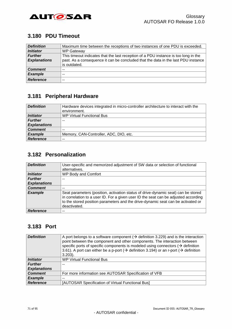
Glossary AUTOSAR FO Release 1.0.0
71 of 95 Document ID 055: AUTOSAR_TR_Glossary
- AUTOSAR confidential -
3.180 PDU Timeout
Definition Maximum time between the receptions of two instances of one PDU is exceeded.
Initiator WP Gateway
Further Explanations
This timeout indicates that the last reception of a PDU instance is too long in the past. As a consequence it can be concluded that the data in the last PDU instance is outdated.
Comment --
Example --
Reference --
3.181 Peripheral Hardware
Definition Hardware devices integrated in micro-controller architecture to interact with the environment.
Initiator WP Virtual Functional Bus
Further Explanations
--
Comment --
Example Memory, CAN-Controller, ADC, DIO, etc.
Reference --
3.182 Personalization
Definition User-specific and memorized adjustment of SW data or selection of functional alternatives.
Initiator WP Body and Comfort
Further Explanations
--
Comment --
Example Seat parameters (position, activation status of drive-dynamic seat) can be stored in correlation to a user ID. For a given user ID the seat can be adjusted according to the stored position parameters and the drive-dynamic seat can be activated or deactivated.
Reference --
3.183 Port
Definition A port belongs to a software component ( definition 3.229) and is the interaction point between the component and other components. The interaction between specific ports of specific components is modeled using connectors ( definition 3.61). A port can either be a p-port ( definition 3.194) or an r-port ( definition 3.203).
Initiator WP Virtual Functional Bus
Further Explanations
--
Comment For more information see AUTOSAR Specification of VFB
Example --
Reference [AUTOSAR Specification of Virtual Functional Bus]
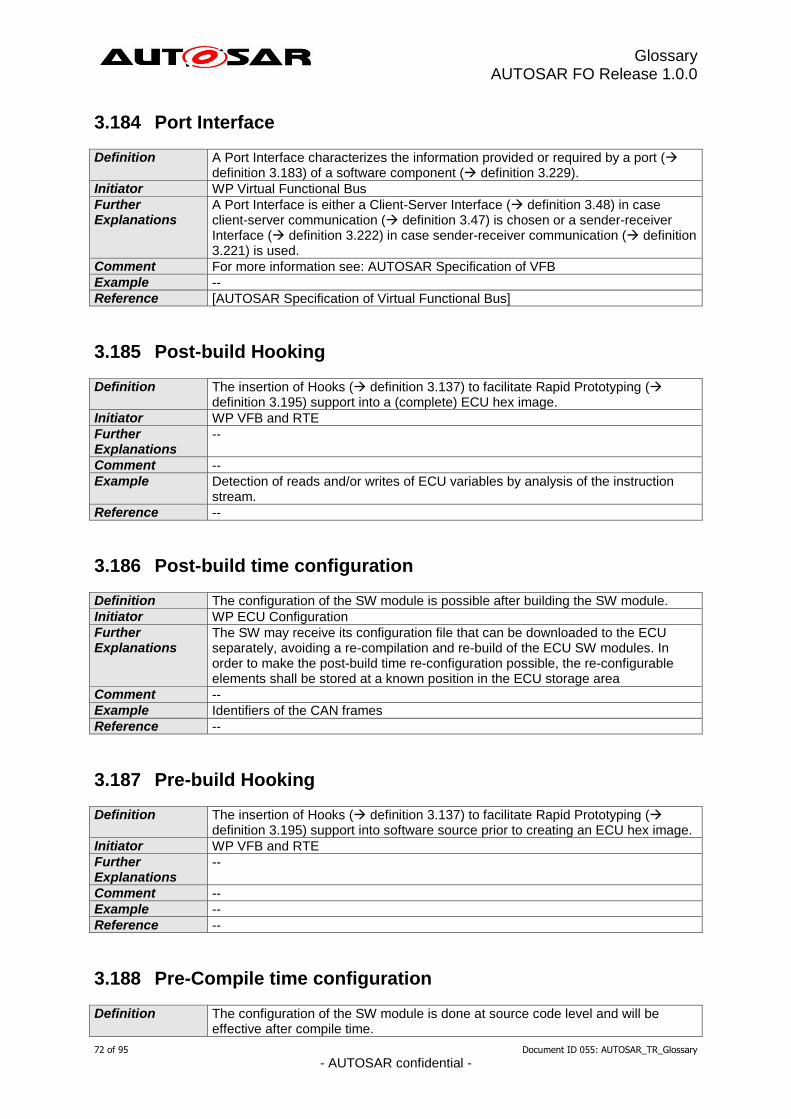
Glossary AUTOSAR FO Release 1.0.0
72 of 95 Document ID 055: AUTOSAR_TR_Glossary
- AUTOSAR confidential -
3.184 Port Interface
Definition A Port Interface characterizes the information provided or required by a port ( definition 3.183) of a software component ( definition 3.229).
Initiator WP Virtual Functional Bus
Further Explanations
A Port Interface is either a Client-Server Interface ( definition 3.48) in case client-server communication ( definition 3.47) is chosen or a sender-receiver Interface ( definition 3.222) in case sender-receiver communication ( definition 3.221) is used.
Comment For more information see: AUTOSAR Specification of VFB
Example --
Reference [AUTOSAR Specification of Virtual Functional Bus]
3.185 Post-build Hooking
Definition The insertion of Hooks ( definition 3.137) to facilitate Rapid Prototyping ( definition 3.195) support into a (complete) ECU hex image.
Initiator WP VFB and RTE
Further Explanations
--
Comment --
Example Detection of reads and/or writes of ECU variables by analysis of the instruction stream.
Reference --
3.186 Post-build time configuration
Definition The configuration of the SW module is possible after building the SW module.
Initiator WP ECU Configuration
Further Explanations
The SW may receive its configuration file that can be downloaded to the ECU separately, avoiding a re-compilation and re-build of the ECU SW modules. In order to make the post-build time re-configuration possible, the re-configurable elements shall be stored at a known position in the ECU storage area
Comment --
Example Identifiers of the CAN frames
Reference --
3.187 Pre-build Hooking
Definition The insertion of Hooks ( definition 3.137) to facilitate Rapid Prototyping ( definition 3.195) support into software source prior to creating an ECU hex image.
Initiator WP VFB and RTE
Further Explanations
--
Comment --
Example --
Reference --
3.188 Pre-Compile time configuration
Definition The configuration of the SW module is done at source code level and will be effective after compile time.
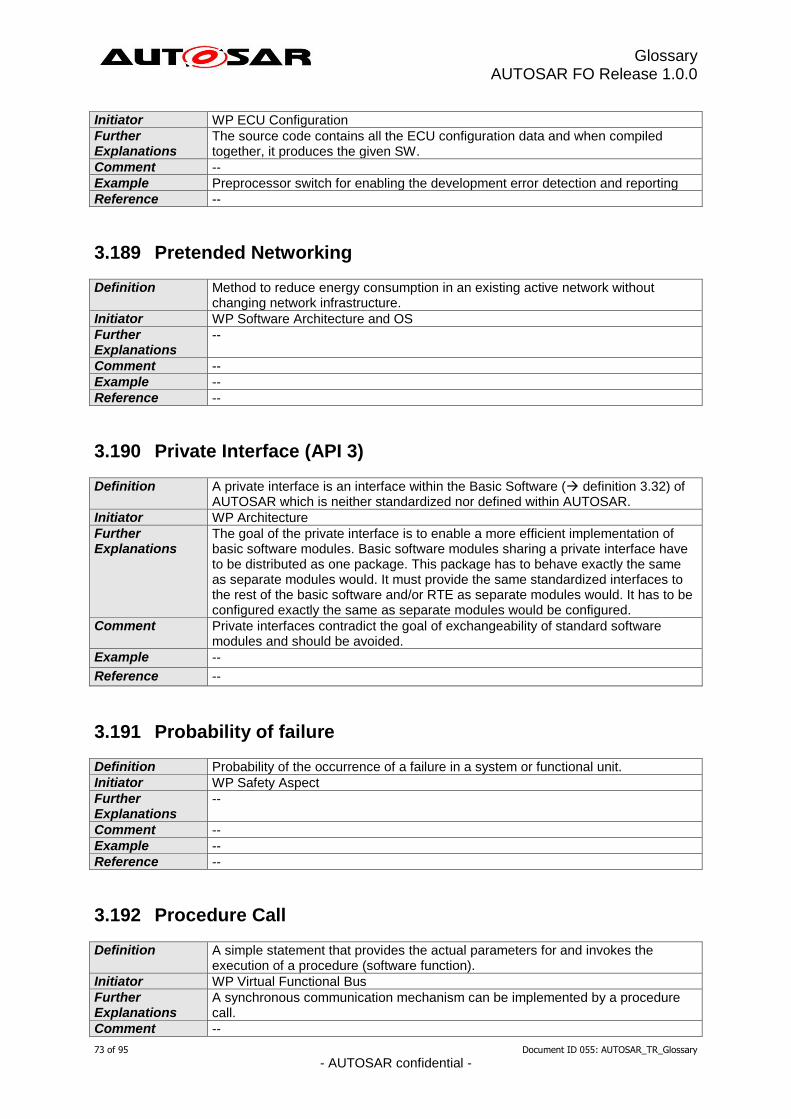
Glossary AUTOSAR FO Release 1.0.0
73 of 95 Document ID 055: AUTOSAR_TR_Glossary
- AUTOSAR confidential -
Initiator WP ECU Configuration
Further Explanations
The source code contains all the ECU configuration data and when compiled together, it produces the given SW.
Comment --
Example Preprocessor switch for enabling the development error detection and reporting
Reference --
3.189 Pretended Networking
Definition Method to reduce energy consumption in an existing active network without changing network infrastructure.
Initiator WP Software Architecture and OS
Further Explanations
--
Comment --
Example --
Reference --
3.190 Private Interface (API 3)
Definition A private interface is an interface within the Basic Software ( definition 3.32) of AUTOSAR which is neither standardized nor defined within AUTOSAR.
Initiator WP Architecture
Further Explanations
The goal of the private interface is to enable a more efficient implementation of basic software modules. Basic software modules sharing a private interface have to be distributed as one package. This package has to behave exactly the same as separate modules would. It must provide the same standardized interfaces to the rest of the basic software and/or RTE as separate modules would. It has to be configured exactly the same as separate modules would be configured.
Comment Private interfaces contradict the goal of exchangeability of standard software modules and should be avoided.
Example --
Reference --
3.191 Probability of failure
Definition Probability of the occurrence of a failure in a system or functional unit.
Initiator WP Safety Aspect
Further Explanations
--
Comment --
Example --
Reference --
3.192 Procedure Call
Definition A simple statement that provides the actual parameters for and invokes the execution of a procedure (software function).
Initiator WP Virtual Functional Bus
Further Explanations
A synchronous communication mechanism can be implemented by a procedure call.
Comment --
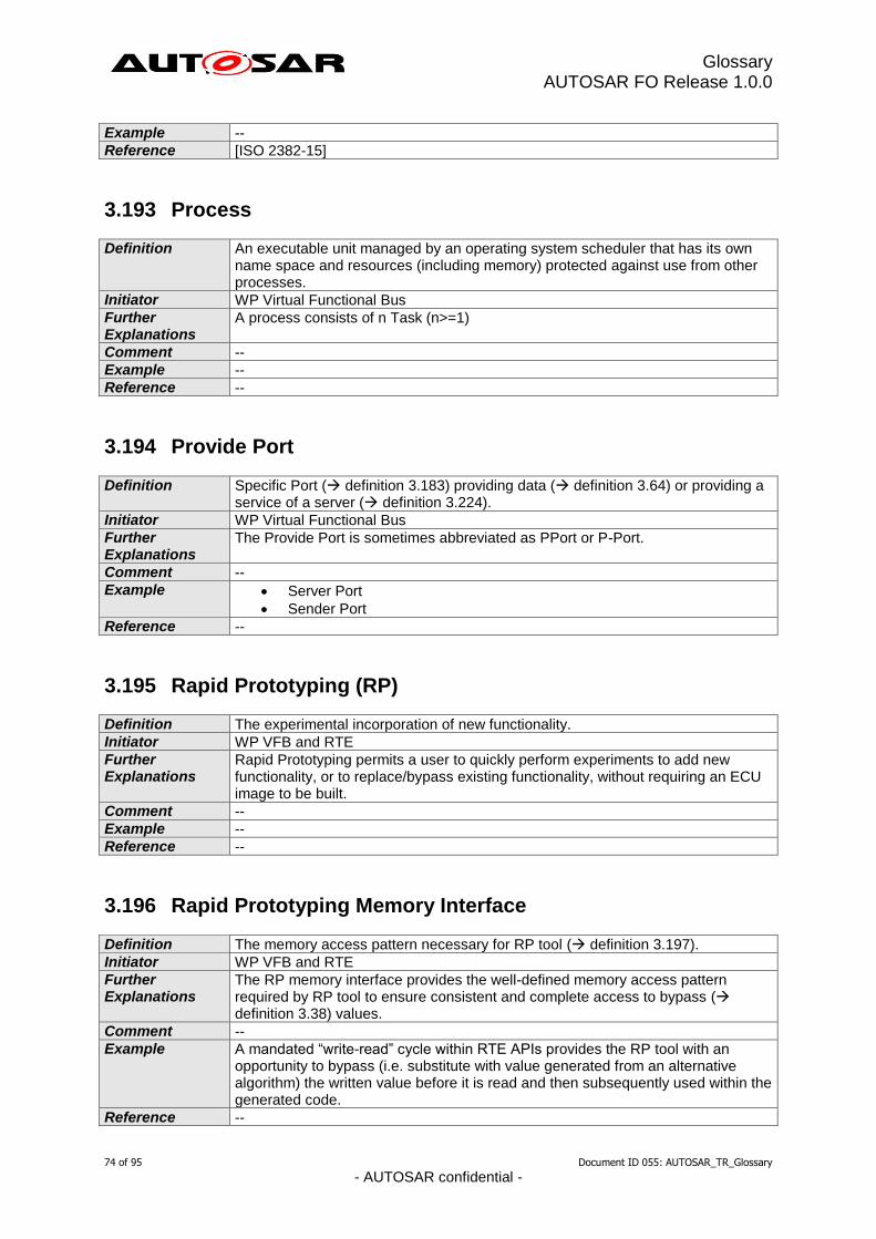
Glossary AUTOSAR FO Release 1.0.0
74 of 95 Document ID 055: AUTOSAR_TR_Glossary
- AUTOSAR confidential -
Example --
Reference [ISO 2382-15]
3.193 Process
Definition An executable unit managed by an operating system scheduler that has its own name space and resources (including memory) protected against use from other processes.
Initiator WP Virtual Functional Bus
Further Explanations
A process consists of n Task (n>=1)
Comment --
Example --
Reference --
3.194 Provide Port
Definition Specific Port ( definition 3.183) providing data ( definition 3.64) or providing a service of a server ( definition 3.224).
Initiator WP Virtual Functional Bus
Further Explanations
The Provide Port is sometimes abbreviated as PPort or P-Port.
Comment --
Example Server Port
Sender Port
Reference --
3.195 Rapid Prototyping (RP)
Definition The experimental incorporation of new functionality.
Initiator WP VFB and RTE
Further Explanations
Rapid Prototyping permits a user to quickly perform experiments to add new functionality, or to replace/bypass existing functionality, without requiring an ECU image to be built.
Comment --
Example --
Reference --
3.196 Rapid Prototyping Memory Interface
Definition The memory access pattern necessary for RP tool ( definition 3.197).
Initiator WP VFB and RTE
Further Explanations
The RP memory interface provides the well-defined memory access pattern required by RP tool to ensure consistent and complete access to bypass ( definition 3.38) values.
Comment --
Example A mandated “write-read” cycle within RTE APIs provides the RP tool with an opportunity to bypass (i.e. substitute with value generated from an alternative algorithm) the written value before it is read and then subsequently used within the generated code.
Reference --
Glossary AUTOSAR FO Release 1.0.0
75 of 95 Document ID 055: AUTOSAR_TR_Glossary
- AUTOSAR confidential -
3.197 Rapid Prototyping Tool
Definition Software and/ or hardware tools to support Rapid Prototyping ( definition 3.195).
Initiator WP VFB and RTE
Further Explanations
--
Comment --
Example Dedicated prototyping interfaces on ECUs accessed by PC-based software tools.
Reference --
3.198 Rate Conversion
Definition Operation to change the timing between two transmissions of the same PduId on one physical Network.
Initiator WP COM Stack
Further Explanations
--
Comment --
Example --
Reference --
3.199 Redundancy
Definition Existence of means in addition to the means that would be sufficient for an element to perform a required function or to represent information.
Initiator WP Safety Aspect
Further Explanations
Redundancy is used in ISO 26262 with respect to achieving a safety goal, a specified safety requirement, or representing safety-related information.
Comment --
Example Duplicated functional components can be an instance of redundancy for the purpose of increasing availability or allowing fault detection. The addition of parity bits to data representing safety-related information provides redundancy for the purpose of allowing fault detection.
Reference [ISO DIS 26262, Part 1]
3.200 Reentrancy
Definition In AUTOSAR a Function ( definition 3.127) is called reentrant if it can be interrupted in the middle of its execution and then safely called again ("re-entered") before its previous invocations complete execution. AUTOSAR differs between
(full) reentrancy
non reentrancy and
conditional reentrancy.
Initiator WP Architecture
Further Explanations
Reentrancy is always considered from the viewpoint of the caller. A Function which is conditional reentrant has to document the conditions for the reentrancy. Typical cases for conditional reentrancy are functions which are reentrant as long as a function parameter is different to (possible) ongoing calls.
Comment An implementation of a Function might be reentrant for one system but only conditional reentrant (or even non reentrant) for another one. It always depend how the reentrancy was realized (e.g. locks). As an example, just consider a function which uses interrupt locks to realize full reentrancy on a single core

Glossary AUTOSAR FO Release 1.0.0
76 of 95 Document ID 055: AUTOSAR_TR_Glossary
- AUTOSAR confidential -
system. If this implementation is used in a multi core system its reentrancy will only be conditional reentrant for calls from the same core.
Example --
Reference --
3.201 Reliability
Definition Probability of a system or functional unit to perform as expected under specified conditions within a time interval.
Initiator WP Safety Aspect
Further Explanations
--
Comment --
Example --
Reference --
3.202 Relocatability
Definition Capability of a software part being executed on different hardware environments without changing the code of the software part.
Initiator WP Virtual Functional Bus
Further Explanations
--
Comment --
Example --
Reference --
3.203 Require Port
Definition Specific Port ( definition 3.183) requiering data ( definition 3.64) or requiering a service of a server.
Initiator WP Virtual Functional Bus
Further Explanations
The Require Port is sometimes abbreviated as RPort or R-Port.
Comment --
Example Client Port
Receiver Port
Reference --
3.204 Required property
Definition A required property or quality of a design entity (e.g. SW component or system) is a property or quality which has to be fulfilled by the environment of this design entity.
Initiator WP Body and Comfort
Further Explanations
A property or quality can be required by a stakeholder (e.g. customer) or another design entity.
Comment --
Example 1) In order to meet its functionality, a SW component A requires a minimum temporal resolution of a signal (information on a required port) which has to be fulfilled by SW component B. 2) SW component requires to be activated by the runtime environment every
Glossary AUTOSAR FO Release 1.0.0
77 of 95 Document ID 055: AUTOSAR_TR_Glossary
- AUTOSAR confidential -
100ms with a jitter of 10ms.
Reference Compare term asserted property ( definition 3.9)
3.205 Residual Error Rate
Definition The ratio of the number of bits, unit elements, or blocks incorrectly received and undetected, to the total number of bits, unit elements, characters, or blocks sent.
Initiator WP Functional Safety and Processes
Further Explanations
--
Comment --
Example --
Reference --
3.206 Resource
Definition A resource is a required but limited hardware entity of an ECU ( definition 3.80), which in general can be accessed concurrently, but not simultaneously, by multiple software entities.
Initiator WP Virtual Functional Bus
Further Explanations
--
Comment The OSEK definition [ISO 17356-3: OS] cannot be used, due to the specific usage in ISO 17356.
Example CPU-load, interrupts (mechanism itself and the resulting CPU-load), memory, peripheral hardware, communication, …
Reference --
3.207 Resource-Management
Definition Entity which controls the use of resources ( definition 3.206).
Initiator WP Virtual Functional Bus
Further Explanations
The main functionality of resource management is the control of simultaneous use of a single resource by several entities, e.g. scheduling of requests, multiple access protection.
Comment --
Example OS-scheduler (CPU-load management)
Reference --
3.208 Response Time
Definition Time between receiving a stimulus and delivering an appropriate response or reaction.
Initiator WP SW Component Template
Further Explanations
The response time describes the time between a stimulus like e.g. the state change of hardware or software entity and the expected reaction of the system (e.g. response, actuator activation). Synonym: reaction time See also: execution time, worst case execution time and worst case response time.
Comment --
Example --
Glossary AUTOSAR FO Release 1.0.0
78 of 95 Document ID 055: AUTOSAR_TR_Glossary
- AUTOSAR confidential -
Reference --
3.209 Risk
Definition Combination of the probability of occurrence of harm and the severity of that harm.
Initiator WP Safety Aspect
Further Explanations
--
Comment --
Example --
Reference [ISO DIS 26262, Part 1]
3.210 Robustness
Definition Ability of a system or functional unit to perform as expected also under unexpected conditions.
Initiator WP Safety Aspect
Further Explanations
--
Comment --
Example --
Reference --
3.211 RTE Event
Definition An RTE Event encompasses all possible situations that can trigger execution of a runnable entity ( definition 3.212) by the RTE. Thus they can address timing, data sending and receiving, invoking operations, call server returning, mode switching, or external events. RTE Events can either activate a runnable entity or wakeup a runnable entity at its waitpoints.
Initiator Stefaan Sonck Thiebaut
Further Explanations
Note ‘event’ in this context is not necessarily synonymous with ‘RTEEvent’ as defined in the VFB specification. In particular, RTE Events that result from communication are handled by communication-triggered runnable entities.
Comment Events can have a variety of sources including time.
Example Scheduling of runnable entities from angular position, e.g. a crankshaft, that are used to trigger an interrupt and hence an RTE notification. A software component needs to perform a regular interval, e.g. flash an LED, reset a watchdog, etc.
Reference --
3.212 Runnable Entity
Definition A Runnable Entity is a part of an Atomic Software-Component ( definition 3.14) which can be executed and scheduled independently from the other Runnable Entities of this Atomic Software-Component. It is described by a sequence of instructions that can be started by the RTE (definition 3.211). Each runnable entity is associated with exactly one Entry Point (definition 3.83).
Initiator WP Virtual Functional Bus
Further Explanations
A Runnable Entity contains at least two points for the Scheduler ( definition 3.218): 1 Entry Point ( definition 3.83) and 1 Exit Point ( definition 3.89).
Glossary AUTOSAR FO Release 1.0.0
79 of 95 Document ID 055: AUTOSAR_TR_Glossary
- AUTOSAR confidential -
Due to the reason that an Atomic Software Component is not dividable, all its Runnable Entities are executed on the same ECU.
Comment In general a task in the runtime system consists out of n Runnable Entities of m Atomic Software-Components.
Example Server function of a Software Component.
Reference --
3.213 SAE J1939
Definition SAE J1939 is a vehicle bus standard created by the SAE (Society of Automotive Engineers, a USA standards body) for car and heavy duty truck industries.
Initiator WP COM Stack
Further Explanations
The J1939 standard encompasses the following areas: - bus physics (J1939/11, J1939/15) - CAN message layout (J1939/21) - request/response and multi packet transport protocols (J1939/21) - network management used to assign a unique address to each node (J1939/81) - diagnostics layer comparable to UDS in complexity (J1939/73) - standardized application signals and messages (J1939/71)
Comment The J1939 standard is used by most truck manufacturers worldwide and is prescribed for OBD in some states of the USA. It is also used as a base for other standards for maritime (NMEA 2000), agricultural (ISO 11783), and military (MilCAN A) applications.
Example --
Reference http://www.sae.org/
3.214 Safety
Definition Absence of unreasonable risk.
Initiator WP Virtual Functional Bus
Further Explanations
--
Comment --
Example --
Reference [ISO DIS 26262, Part 1]
3.215 Safety Protocol
Definition A communication protocol defining the necessary mechanisms to ensure the integrity of transmitted data and to detect any communication related error.
Initiator WP Functional Safety and Processes
Further Explanations
--
Comment --
Example --
Reference --
3.216 Sample Application
Definition Defined system used for evaluation purposes.
Initiator WP Virtual Functional Bus

Glossary AUTOSAR FO Release 1.0.0
80 of 95 Document ID 055: AUTOSAR_TR_Glossary
- AUTOSAR confidential -
Further Explanations
The application may be simplified for better understanding within the evaluation phase.
Comment --
Example Diagnosis Application Exterior Light Management
Reference --
3.217 Scalability
Definition The degree to which assets can be adapted to specific target environments for various defined measures.
Initiator WP Virtual Functional Bus
Further Explanations
--
Comment Target environment introduced compared to EAST-Glossary.
Example --
Reference [EAST-Glossary]
3.218 Scheduler
Definition The scheduler handles the scheduling of the tasks/runnable entities (definition 3.249 / 3.212) according to the priority and scheduling policy (pre-defined or configurable). It has the responsibility to decide during run-time when which task can run on on the CPU of the ECU.
Initiator WG System Team
Further Explanations
There are many strategies (priority-based, time-triggered, round-robbin, …) a scheduler can use, depending of the selected and/or implemented algorythms
Comment --
Example --
Reference [AUTOSAR Specification of Virtual Functional Bus]
3.219 SDU
Definition SDU is the abbreviation of “Service Data Unit”. It is the data passed by an upper layer, with the request to transmit the data. It is as well the data, which is extracted after reception by the lower layer and passed to the upper layer.
Initiator WP Architecture
Further Explanations
A SDU is part of a PDU ( definition 3.178).
Comment --
Example --
Reference --
3.220 Security
Definition Protection of data, software entities or resources from accidental or malicious acts.
Initiator WP Virtual Functional Bus
Further Explanations
--
Comment Slightly adapted norm.
Example --
Glossary AUTOSAR FO Release 1.0.0
81 of 95 Document ID 055: AUTOSAR_TR_Glossary
- AUTOSAR confidential -
Reference [ISO 2382-8]
3.221 Sender-Receiver Communication
Definition A communication pattern which offers asyncronous distribution of information where a sender communicates information to one or more receivers, or a receiver receives information from one or several senders.
Initiator WP Virtual Functional Bus
Further Explanations
The process of sending data does not block the sender and the sender usually gets no response from the receivers
Comment Often used for data or event distribution
Example --
Reference [AUTOSAR Specification of Virtual Functional Bus]
3.222 Sender-Receiver Interface
Definition A sender-receiver interface is a special kind of port-interface ( definition 3.184) used for the case of sender-receiver communication ( definition 3.221). The sender-receiver interface defines the data-elements which are sent by a sending component (which has a p-port providing the sender-receiver interface) or received by a receiving component (which has an r-port requiring the sender-receiver interface).
Initiator Stefaan Sonck Thiebaut
Further Explanations
--
Comment A special kind of Port-Interface
Example --
Reference [AUTOSAR Specification of Virtual Functional Bus]
3.223 Sensor/Actuator SW-Component
Definition SW-Component ( definition 3.229) dedicated to the control of a sensor or actuator.
Initiator WP Virtual Functional Bus
Further Explanations
There will be several Sensor/ Actuator SW-Cs in each ECU. In general there will be one Sensor/Actuator SW-C for each sensor and one for each actuator (=> number of Sensor/Actuator SW-C = number of sensors + number of actuators).
Comment --
Example --
Reference --
3.224 Server
Definition Software entity which provides services for clients ( definition 3.46).
Initiator WP Virtual Functional Bus
Further Explanations
The server ( definition 3.224) and the clients using its service might be located on one ECU or distributed on different calculation units (e.g. ECU).
Comment Adapted from Balzert.
Example --
Reference [Balzert99]
Glossary AUTOSAR FO Release 1.0.0
82 of 95 Document ID 055: AUTOSAR_TR_Glossary
- AUTOSAR confidential -
3.225 Service
Definition A service is a type of operation that has a published specification of interface and behavior, involving a contract between the provider of the capability and the potential clients.
Initiator WP Virtual Functional Bus
Further Explanations
--
Comment --
Example Diagnosis service, …
Reference [EAST-Glossary]
3.226 Service Port
Definition A Service Port is a Port ( definition 3.183) of an SW-C ( definition 3.229), Complex Driver ( definition 3.53) and/or ECU Abstraction ( definition 3.77) connected to an AUTOSAR Service ( definition 3.27).
Initiator WP Virtual Functional Bus
Further Explanations
The interface of a Service Port has to be a Standardized AUTOSAR Interface ( definition 3.22 and 3.237). A Service Port does not need to be connected to another Port in the VFB View ( definition 3.265).
Comment If a service is provided by the ECU where a specific Atomic Software Component is located the VFB View is sufficient. If a service is provided by another ECU the connection of the service call to the service has to be done explicitly during the mapping step.
Example Write data to non volatile memory.
Reference --
3.227 Services Layer
Definition The Services Layer is the highest layer of the Basic Software which also applies for its relevance for the application software: while access to I/O signals is covered by the Hardware Abstraction Layer, the Services Layer offers Operating system services Vehicle network communication and management services Memory services (NVRAM management) Diagnosis Services (including KWP2000 interface and error memory) ECU state management Task: Provide basic services for application and basic software modules
Initiator WP Architecture
Further Explanations
The Services Layer consists of the following parts: Communication Services Memory Services System Services
Comment --
Example Network Management, NVRAM Manager, ECU State Manager
Reference [AUTOSAR Software Architecture]
3.228 Shipping
Definition Component shipment refers to the action of a supplier releasing a software component (also a composition) to the system integrator. The integrator will gather
Glossary AUTOSAR FO Release 1.0.0
83 of 95 Document ID 055: AUTOSAR_TR_Glossary
- AUTOSAR confidential -
all shipments of the components that make up the whole system and then map them to ECUs.
Initiator WP SW Component Template
Further Explanations
--
Comment --
Example --
Reference --
3.229 Software Component (SW-C)
Definition Software-Components are architectural elements that provide and/or require interfaces and are connected to each other through the Virtual Function Bus to fulfill architectural responsibilities.
Initiator WP Virtual Functional Bus
Further Explanations
A Software Component has a formal description defined by the software component template ( definition 3.251). Software Components can be abbreviated as SW-Cs. SW-Cs may be atomic components, parameter components or compositions. Also the software modules providing the Software Component Interface ( definition 3.230) of a Basic Software Module ( definition 3.33) are called Software Components.
Comment --
Example --
Reference --
3.230 Software Component Interface (SW-CI)
Definition A SoftWare-Component Interface is the sum of all interfaces offered by the Basic Software ( definition 3.32), towards the SW-Cs ( definition 3.229).
Initiator WP Conformance Test Specification
Further Explanations
A SW-CI denotes the interface between an SW-C and the underlying Basic Software cluster including the RTE. The SW-CI therefore comprises all API ( definition 3.5), functions ( definition 3.127) and Callbacks ( definition 3.40) that the SW-C requires from and provides to the Basic Software (generally by means of RTE mechanisms). It includes also the mechanisms allowing SW-Cs sharing the SW-CI to communicate with one another. For the purposes of this definition, the Basic Software clustered on an ECU can be designed according to ICC1, 2 and 3.
Comment The term has been introduced as a short-hand to aid in discussion of the conformance of the content of Basic Software clusters of conformance class ICC1 / 2 and to define the backward compatibility between releases and revisions. However, since from the SW-C perspective, the clustering of the Basic Software is invisible, the Component Interface is applicable to all potential Basic Software conformance classes (ICC1, ICC2, ICC3) in the same way.
Example --
Reference Network Interface (NWI)
3.231 Software Configuration
Definition The arrangement of software elements in a SW system.
Initiator WP Virtual Functional Bus
Further Explanations
A software element is a clearly definable software part. A software configuration is a selection version of software modules, software components, parameters and
Glossary AUTOSAR FO Release 1.0.0
84 of 95 Document ID 055: AUTOSAR_TR_Glossary
- AUTOSAR confidential -
generator configurations. Calibration and Variant Coding ( definition 3.258) can be regarded as subset of Software Configuration.
Comment --
Example --
Reference [EAST-Glossary]
3.232 Software Interrupt
Definition Interrupt triggered by SW event.
Initiator WP Virtual Functional Bus
Further Explanations
SW events are for example calling an operating system service, starting a process with higher priority.
Comment --
Example --
Reference Translation/Adaptation from [VDI Lexikon]
3.233 Software Signal
Definition A Software Signal is an asynchronous event transmitted between one process and another.
Initiator WP Virtual Functional Bus
Further Explanations
A SW Signal is the software implementation of an (control-) information. Additionally it may have attributes (e.g. freshness, data type, …). It is exchanged between SW-Components.
Comment --
Example --
Reference --
3.234 Special Periphery Access
Definition Special functions to standard peripheral devices or special peripherals.
Initiator WP Virtual Functional Bus
Further Explanations
Is only used when, because of technical issues, no standard periphery access can be used
Comment --
Example --
Reference --
3.235 Standard Periphery Access
Definition Standard functions to typical standard peripheral devices that are available on an ECU (most microcontroller integrated) used in automotive embedded applications.
Initiator WP Virtual Functional Bus
Further Explanations
--
Comment --
Example Digital Input/Output, Analog/Digital Converter, Pulse Width (De)Modulator, EEPROM, FLASH, Capture Compare Unit, Watchdog Timer
Reference --
Glossary AUTOSAR FO Release 1.0.0
85 of 95 Document ID 055: AUTOSAR_TR_Glossary
- AUTOSAR confidential -
3.236 Standardized AUTOSAR Blueprint
Definition A Standardized AUTOSAR Blueprint is an AUTOSAR Blueprint ( definition 3.19) standardized within the AUTOSAR project. Its derived objects are considered as being standardized within the AUTOSAR project as well.
Initiator WP Application Interfaces
Further Explanations
Blueprints were introduced within the AUTOSAR projects to enable standardization of ports without standardizing the static view of the architecture (i.e. the software components providing or requesting the ports). Sometimes it is not possible to standardize all attributes of an AUTOSAR element because the values of some attributes are project specific. Nevertheless it enables better collaboration if some of the attributes are standardized. Additionally blueprints enable adding descriptions and long names in different languages.
Comment --
Example --
Reference [MOD AI Specification]
3.237 Standardized AUTOSAR Interface
Definition This is an AUTOSAR Interface which is standardized within the AUTOSAR project.
Initiator WP Virtual Functional Bus
Further Explanations
AUTOSAR Services ( definition 3.27) interact with other components through a Standardized AUTOSAR Interface. AUTOSAR Interfaces can be derived from AUTOSAR Application Interfaces ( definition 3.17).
Comment --
Example --
Reference --
3.238 Standardized Blueprint
Definition A Blueprint ( definition 3.35) is called a Standardized Blueprint if the derived objects are considered as being standardized as well. It also includes that additionally concrete standardized rules exist how to specify the blueprint as well as how to derive an object from that blueprint. This is typically not done for a specific blueprint but for all blueprints of the same class.
Initiator WP Application Interfaces
Further Explanations
--
Comment --
Example --
Reference --
3.239 Standardized Interface
Definition A software interface is called Standardized Interface if a concrete standardized API exists.
Initiator WP Virtual Functional Bus
Further Explanations
Modules in the Basic Software interact which each other through Standardized Interfaces.
Comment --
Example ISO 17356-4: COM Interface
Glossary AUTOSAR FO Release 1.0.0
86 of 95 Document ID 055: AUTOSAR_TR_Glossary
- AUTOSAR confidential -
Reference --
3.240 Standard Software
Definition Standard Software is software which provides schematic independent infrastructural functionalities on an ECU. It contains only Standardized Interfaces ( definition 3.239), Standardized AUTOSAR Interfaces ( definition 3.237) and/or Private Interfaces ( definition 3.190).
Initiator WP Virtual Functional Bus
Further Explanations
--
Comment --
Example OSEK (ISO 17356), MCAL, Services
Reference --
3.241 Static Configuration
Definition A setup where the routing configuration cannot be changed during normal operation of the gateway.
Initiator WP Gateway
Further Explanations
Static configuration doesn't allow reconfiguration of the routing during normal operation e.g. during driving. Static configuration does not restrict the update of the configuration in specific maintenance operation modes (e.g. programming mode).
Comment --
Example A software update may change a routing configuration such that a PDU is routed into two instead of one destination networks.
Reference --
3.242 Surveillance
Definition Systematic iteration of a reduced full-set assessment ( definition 3.10) as a basis for maintaining the validity of the full-set assessment.
Initiator WP Exploitation
Further Explanations
Within AUTOSAR context, reduced set surveillances of the accredited party are scheduled yearly between the full-set assessments.
Comment Supplementary full-set assessments are scheduled.
Example --
Reference [ISO/IEC 17000]
3.243 Synchronize
Definition To make two or more events or operations to occur at the same predefined moment in time.
Initiator WP COM Stack
Further Explanations
--
Comment --
Example Two NM Channels can enter Bus Sleep Mode at the same time ("synchronized network sleep") or they can be ordered to go to sleep at the same time ("synchronized shutdown initiation").
Reference AUTOSAR Generic NM Interface
Glossary AUTOSAR FO Release 1.0.0
87 of 95 Document ID 055: AUTOSAR_TR_Glossary
- AUTOSAR confidential -
3.244 Synchronous Communication
Definition A communication is synchronous when the calling software entity is blocked until the called operation is evaluated. The calling software entity continues its operation by getting the result.
Initiator WP Virtual Functional Bus
Further Explanations
Synchronous communication between distributed functional units has to be implemented as remote procedure call.
Comment Are further mechanisms possible?
Example --
Reference --
3.245 Synchronous Function
Definition A function is called synchronous if the described functionality is guaranteed to be completed the moment the function returns to the caller.
Initiator WP Software Architecture and OS
Further Explanations
--
Comment --
Example --
Reference --
3.246 System
Definition An integrated composite that consists of one or more of the processes, hardware, software, facilities and people, that provides a capability to satisfy a stated need or objective.
Initiator WP Virtual Functional Bus
Further Explanations
--
Comment ITEA EAST uses IEEE 14407 standard. Here not applicable because of problem with the definition of function. One correct interpretation is: - it might be a composition of one or more ECUs
Example Braking system
Reference [ISO 12207]
3.247 System Constraint
Definition Boundary conditions that restrict the Design-Freedom of the (cars E/E-) System.
Initiator WP System Constraint Template
Further Explanations
The design of ECU Networks and the distribution of functionalities to ECUs are limited by several constrains. These constraints result mostly by the communication matrix and safety requirements
Comment --
Example An existing communication matrix that restricts the distribution of signals to frames is a system constraint. Another system constraint is a safety requirement that does not allow to map a specified Software component to specific ECU.
Reference --
Glossary AUTOSAR FO Release 1.0.0
88 of 95 Document ID 055: AUTOSAR_TR_Glossary
- AUTOSAR confidential -
3.248 System Signal
Definition The system signal represents the communication system's view of data exchanged between SW components which reside on different ECUs. The system signals allow to represent this communication in a flattened structure, with (at least) one system signal defined for each data element sent or received by a SW component instance. If data has to be sent over gateways, there is still only one system signal representing this data. The representation of the data on the individual communication systems is done by the cluster signals.
Initiator WP System Constraint Template
Further Explanations
--
Comment --
Example --
Reference --
3.249 Task
Definition A Task is the smallest schedulable unit managed by the OS. The OS decides when which task can run on the CPU of the ECU.
Initiator WP Virtual Functional Bus
Further Explanations
A runnable entity ( definition 3.212) of a software component runs in the context of a task. Also the Basic Software Modules runs in the context of a task.
Comment --
Example --
Reference [AUTOSAR Specification of Virtual Functional Bus]
3.250 Technical Signal
Definition The technical signal is the physical value of an external event coupled to an AUTOSAR system. Technical signals are represented in SI units (e.g. pressure in PA).
Initiator WP ECU Resource Template
Further Explanations
The term Technical Signal is used when we are referring to the "real world" signal that is under consideration. So typical Technical Signals are temperature, velocity, torque, force, electrical current and voltage, etc.
Comment --
Example --
Reference --
3.251 Template
Definition A template is a structured collection of attributes that are required to formally describe AUTOSAR artifacts like e.g. software components or configurations of ECUs.
Initiator WP Virtual Functional Bus
Further Explanations
The term "Template" stresses the fact that the collected attributes still need to have actual values assigned in order to describe a particular artifact. Those values are collected in a Description. Templates are independent of the technology used for serialization of their respective descriptions. Possible serializations include XML, databases tables and so on.
Comment --
Example The templates defined by AUTOSAR are represented as an UML2.0 model (
Glossary AUTOSAR FO Release 1.0.0
89 of 95 Document ID 055: AUTOSAR_TR_Glossary
- AUTOSAR confidential -
definition 3.23) and an W3C XML Schema ( definition 3.30). Models and descriptions created according to the templates can be exchanged using the language defined in the AUTOSAR XML Schema).
Reference --
3.252 Third party
Definition An organization that is independent of the organization that provides automotive products, which are subject to AUTOSAR conformance testing.
Initiator WP Exploitation
Further Explanations
Criteria for the independence of conformity assessment ( definition 3.10) bodies and accreditation ( definition 3.1) bodies are provided in the International Standard and Guides applicable to their activities.
Comment --
Example --
Reference ISO/IEC 17000]
3.253 Timeout
Definition Notification with respect to deadline violation of an event or task (e.g. while working on/with information: receiving, sending, processing,...).
Initiator WP Virtual Functional Bus
Further Explanations
--
Comment --
Example --
Reference --
3.254 Use Case
Definition A model of the usage by the user of a system in order to realize a certain functional feature of the system.
Initiator WP Virtual Functional Bus
Further Explanations
--
Comment Added certain compared to EAST-glossary.
Example --
Reference [EAST-Glossary]
3.255 Validation
Definition Confirmation by examination and provisions of objective evidence that the particular requirements for a specific intended use are fulfilled.
Initiator WG System Team
Further Explanations
In design and development, validation concerns the process of examining a product to determine conformity with user needs. Validation is normally performed on the final product under defined operating conditions. It may be necessary in earlier stages. “Validated” is used to designate the corresponding status. Multiple validations may be carried out if there are different intended uses. [ISO 8402: 1994]
Comment --
Example --
Glossary AUTOSAR FO Release 1.0.0
90 of 95 Document ID 055: AUTOSAR_TR_Glossary
- AUTOSAR confidential -
Reference [IEEE 1012:1998]
3.256 Variability
Definition Variability of a system is its quality to describe a set of variants. These variants are characterized by variant specific property settings and / or selections.
Initiator WP General Methodology and Configuration
Further Explanations
--
Comment --
Example As an example, such a system property selection manifests itself in a particular “receive port” for a connection.
Reference --
3.257 Variant
Definition A system variant is a concrete realization of a system, so that all its properties have been set respectively selected. The software system has no variability anymore with respect to the binding time.
Initiator WP General Methodology and Configuration
Further Explanations
--
Comment --
Example --
Reference --
3.258 Variant Coding
Definition Adaptation of SW by selection of functional alternatives according to external requirements (e.g. country-dependent or legal restrictions).
Initiator WP Virtual Functional Bus
Further Explanations
The major difference with calibration is that this later doesn’t aim to adapt the SW functionality itself but only aims to adjust the SW to the HW/SW environment, e.g. the calibration of engine control SW that is adjusted to the physical parameters of every engine. Variant Coding also includes vehicle-specific (not user-specific) SW adaptation due to end-customer wishes (e.g. deactivation of speed-dependent automatic locking). Variant Coding is always done after compile time. Used techniques to select variants include end-of-line programming and garage programming.
Comment --
Example Country related adaptation of MMI with respect to speed and/or temperature unit (km/h vs. mph, °C vs. F).
Reference --
3.259 Variation Binding
Definition A variant is the result of a variation binding process that resolves the variability of the system by assigning particular values/selections to all the system’s properties.
Initiator WP General Methodology and Configuration
Further Explanations
--
Comment --
Glossary AUTOSAR FO Release 1.0.0
91 of 95 Document ID 055: AUTOSAR_TR_Glossary
- AUTOSAR confidential -
Example --
Reference --
3.260 Variation Binding Time
Definition The variation binding time determines the step in the methodology at which the variability given by a set of variable properties is resolved.
Initiator WP General Methodology and Configuration
Further Explanations
--
Comment --
Example --
Reference --
3.261 Variation Definition Time
Definition The variation definition time determines the step in the methodology at which the variation points are defined.
Initiator WP General Methodology and Configuration
Further Explanations
--
Comment --
Example --
Reference --
3.262 Variation Point
Definition A variation point indicates that a property is subject to variation. Furthermore, it is associated with a condition and a binding time which define the system context for the selection / setting of a concrete variant.
Initiator WP General Methodology and Configuration
Further Explanations
--
Comment --
Example --
Reference --
3.263 Vendor ID
Definition A vendor ID is a unique identification of the vendor of a software component. All basic software modules (definition 3.33) conformant to the AUTOSAR standard shall provide a readable vendor ID.
Initiator WP Architecture
Further Explanations
AUTOSAR Vendor IDs are used to determine vendors of basic software modules before and during runtime. The mechanism is used to improve bug handling. AUTOSAR currently only provides Vendor IDs to members of the AUTOSAR partnership.
Comment To apply for an AUTOSAR vendor ID the possible member has to send an E-Mail to [email protected]. Within the request name of the company, company address and contact person should be listed.
Example Vendor ID for EEPROM driver is called: EEP_VENDOR_ID
Reference SRS_BSW_00374
Glossary AUTOSAR FO Release 1.0.0
92 of 95 Document ID 055: AUTOSAR_TR_Glossary
- AUTOSAR confidential -
3.264 Verification
Definition Confirmation by examination and provisions of objective evidence that specified requirements have been fulfilled.
Initiator WG System Team
Further Explanations
In design and development, verification concerns the process of examining the result of a given activity to determine conformity with the stated requirement for that activity. “Verified” is used to designate the corresponding status. [ISO 8402: 1994]
Comment --
Example --
Reference [IEEE 1012:1998]
3.265 VFB View
Definition The VFB View describes systems or subsystems in the car independently of these resources; in other words, independently of:
what kind of and how many ECUs are present in the car
on what ECUs the entities in the VFB-View run
how the ECUs are interconnected: what kind of network technology (CAN, LIN,…) and what kind of topology (presence of gateways) is used
Initiator WP Virtual Functional Bus
Further Explanations
In the VFB-View, the system or subsystem under consideration is a Composition which consists out of Connectors and Components.
Comment --
Example --
Reference [AUTOSAR Specification of Virtual Functional Bus]
3.266 Virtual Functional Bus (VFB)
Definition The Virtual Functional Bus is an abstraction of the communication between Atomic Software Components ( definition 3.14) and AUTOSAR Services ( definition 3.27). This abstraction is such that specification of the communication mechanisms is independent from the concrete technology chosen to realize the communication.
Initiator WP Virtual Functional Bus
Further Explanations
After compilation and linking of software for a dedicated ECU ( definition 3.80) the Virtual Functional Bus interfaces are realized by the AUTOSAR Runtime Environment.
Comment --
Example --
Reference --
3.267 Virtual Integration
Definition The simulated, modeled and/or calculated (not real) combination of software entities forming a system ( definition 3.246).
Initiator WP Virtual Functional Bus
Further Explanations
By virtual integration several constraints and/or requirements are checked without the need of real hardware units, like needed CPU load, needed memory, completeness of interfaces, fulfillment of timing requirements etc.).
Glossary AUTOSAR FO Release 1.0.0
93 of 95 Document ID 055: AUTOSAR_TR_Glossary
- AUTOSAR confidential -
Comment --
Example --
Reference --
3.268 Worst Case Execution Time
Definition Maximum possible time during which a program is actually executing
Initiator WP Virtual Functional Bus
Further Explanations
The worst case execution time of a piece of software is the maximum possible time during which the CPU is executing instructions which belong to this piece. The worst case execution time is often identified by analytical methods. It is required to determine if a schedule meets the overall timing requirements. Abbreviation: WCET See also: response time, execution time, worst case response time
Comment This definition has been extended by WP COM
Example --
Reference --
3.269 Worst Case Response Time
Definition Maximum possible time between receiving a stimulus and delivering an appropriate response or reaction.
Initiator WP Virtual Functional Bus
Further Explanations
The worst case response time describes the maximum possible time between a stimulus like e.g. the state change of hardware or software entity and the expected reaction of the system (e.g. response, actuator activation). Typically: worst-case execution-time + infrastructure-overhead + scheduling-policy = worst-case reaction time Synonym: worst case reaction time See also: response time, execution time, worst case execution time
Comment Worst case reaction time was renamed to worst case response time because response time is the more common terminology. This definition has been extended by WP COM.
Example --
Reference --
Glossary AUTOSAR FO Release 1.0.0
94 of 95 Document ID 055: AUTOSAR_TR_Glossary
- AUTOSAR confidential -
Annex 1: Literature
[Balzert99], Balzert, H. “Lehrbuch Grundlagen der Informatik” Spektrum Verlag, Heidelberg, 1999 [DCE-IDL], Remote Procedure Call http://www.opengroup.org/onlinepubs/9629399/chap1.htm [EAST-Glossary], ITEA Project 00009 EAST-EEA Embedded Electronic Architecture “Glossary”, Version 6.1, 2003 [Hyper Dictionary], Hyper Dictionary, 2003 www.HyperDictionary.com [IEEE 1471], Institute of Electrical and Electronics Engineers, Inc. “IEEE 1471-2000: IEEE Recommended Practice for Architectural Description for Software- Intensive Systems”, 2001 [IEEE 1517], Institute of Electrical and Electronics Engineers, Inc. “IEEE 1517-1999: IEEE Standard for Information Technology – Software Life Cycle Processes – Reuse Processes”, 2000 [ISO 12207], International Standardization Organization “ISO/IEC 12207 Information technology – Software life cycle process”, first edition, Geneva, 1995 [ISO 2382-1], International Standardization Organization “ISO/IEC 2382 Part 1 Information technology – Vocabulary – Fundamental Terms”, Third Edition, Geneva, 1993 [ISO 2382-14], International Standardization Organization “ISO/IEC 2382 Part 14 Information technology – Vocabulary – Reliability, maintainability and availability”, Second Edition, Geneva, 1997 [ISO 2382-15], International Standardization Organization “ISO/IEC 2382 Part 15 Information technology – Vocabulary – Programming Languages”, First Edition, Geneva, 1999 [ISO 2382-20], International Standardization Organization “ISO/IEC 2382 Part 20 Information technology – Vocabulary – System Development”, First Edition, Geneva, 1990 [ISO 2382-8], International Standardization Organization “ISO/IEC 2382 Part 1 Information technology – Vocabulary – Security”, Second Edition, Geneva, 1998 [ISO 61511-1], International Standardization Organization “ISO/IEC 61511 Part 1 Information technology – Software life cycle process”, First Edition, Geneva, 1995 [ISO DIS 26262, Part 1], International Standardization Organization “ISO/IEC 26262 Part 1 Road vehicles – Functional safety: Vocabulary”

Glossary AUTOSAR FO Release 1.0.0
95 of 95 Document ID 055: AUTOSAR_TR_Glossary
- AUTOSAR confidential -
[OMG-IDL], http://www.omg.org/technology/documents/formal/corba_2.htm [ISO 17356], ISO versions of the OSEK standards [ISO 7498], Information processing systems -- Open Systems Interconnection -- Basic Reference Model [DIN 40041], DIN 40041 Ausgabe:1990-12 Zuverlässigkeit; Begriffe Deutsche Industrie Norm [VDI Lexikon], Translation/Adaptation from VDI Lexikon Informatik und Kommunikationstechnik, Springer Verlag, Berlin 1999, [IEEE.610.12-1990], IEEE Standard Glossary of Software Engineering Terminology; ISBN 1-55937-067-X, SH13748 [UML 2.0] Unified Modeling Language Superstructure, Version 2.0, OMG Available Specification, ptc/05-07-04. http://www.omg.org/cgi-bin/apps/doc?formal/05-07-04.pdf [IEEE 1394] Firewire, see “isochronous stream” http://www.1394ta.org/Technology/Specifications/specifications.htm [FR_PROTOCOL] FlexRay Communications System Protocol Specification V2.1 http://www.flexray.com/