Embed Size (px)
Citation preview
1© 2015 The MathWorks, Inc.
Developing AUTOSAR Compliant
Embedded Software
Senior Application Engineer
Sang-Ho Yoon
2
Agenda
AUTOSAR Compliant Code Generation
– AUTOSAR Workflows
– Starting from Software Component Descriptions in ARXML files
(Top-Down Approach)
– Starting from Simulink (Bottom-up Approach)
Verification of AUTOSAR ASWC with Model
Verification of AUTOSAR ASWC for Generated Code
3© 2015 The MathWorks, Inc.
AUTOSAR Compliant Code Generation
4
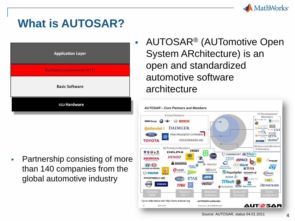
What is AUTOSAR?
AUTOSAR® (AUTomotive Open
System ARchitecture) is an
open and standardized
automotive software
architecture
Partnership consisting of more
than 140 companies from the
global automotive industry
Source: AUTOSAR, status 04.01.2011
5
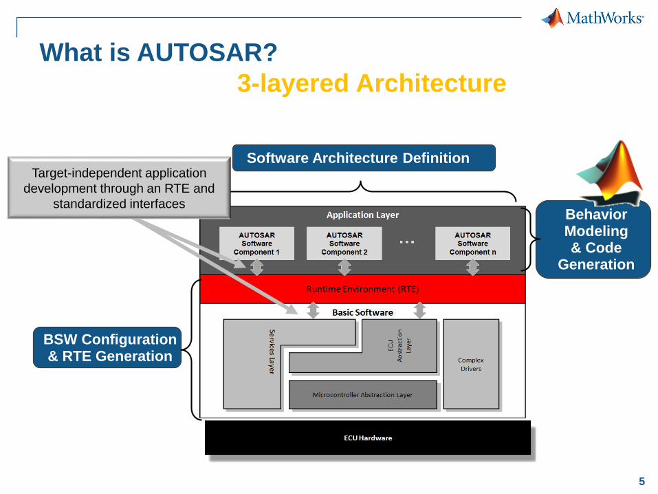
What is AUTOSAR?
3-layered Architecture
Behavior Modeling& Code
Generation
Software Architecture Definition
BSW Configuration& RTE Generation
Target-independent application
development through an RTE and
standardized interfaces
6
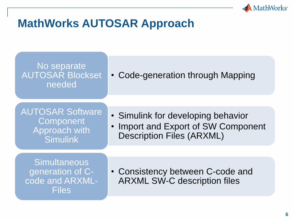
MathWorks AUTOSAR Approach
• Code-generation through MappingNo separate
AUTOSAR Blocksetneeded
• Simulink for developing behavior
• Import and Export of SW Component Description Files (ARXML)
AUTOSAR Software Component
Approach with Simulink
• Consistency between C-code and ARXML SW-C description files
Simultaneous generation of C-
code and ARXML-Files
7
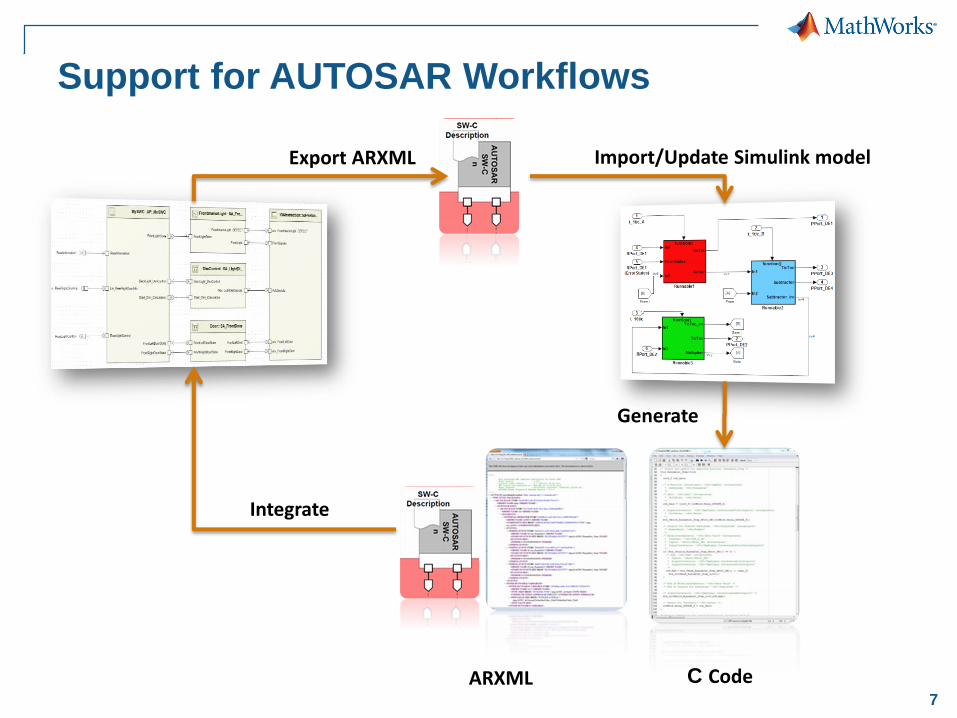
Support for AUTOSAR Workflows
Export ARXML Import/Update Simulink model
C CodeARXML
Generate
Integrate
8
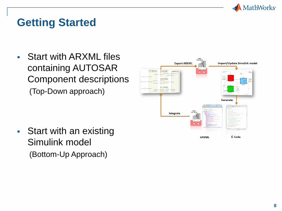
Getting Started
Start with ARXML files
containing AUTOSAR
Component descriptions
(Top-Down approach)
Start with an existing
Simulink model
(Bottom-Up Approach)
9© 2015 The MathWorks, Inc.
Starting from Software Component
Descriptions in ARXML filesTop-Down Approach
10
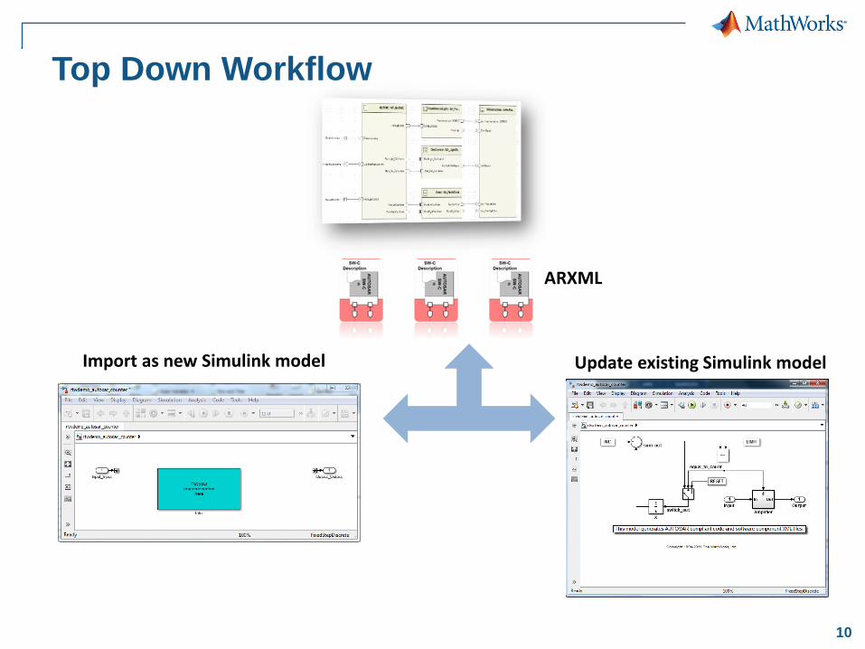
Top Down Workflow
ARXML
Import as new Simulink model Update existing Simulink model
11
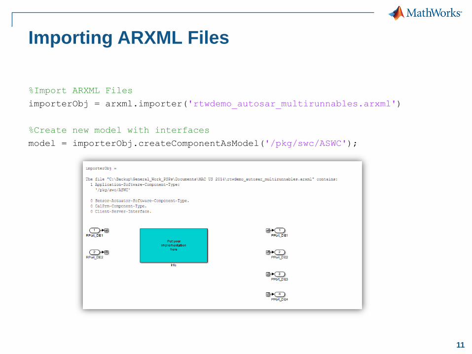
Importing ARXML Files
%Import ARXML Files
importerObj = arxml.importer('rtwdemo_autosar_multirunnables.arxml')
%Create new model with interfaces
model = importerObj.createComponentAsModel('/pkg/swc/ASWC');
12
Design Controller from Requirement
Case Study : Seat Belt Reminder
14
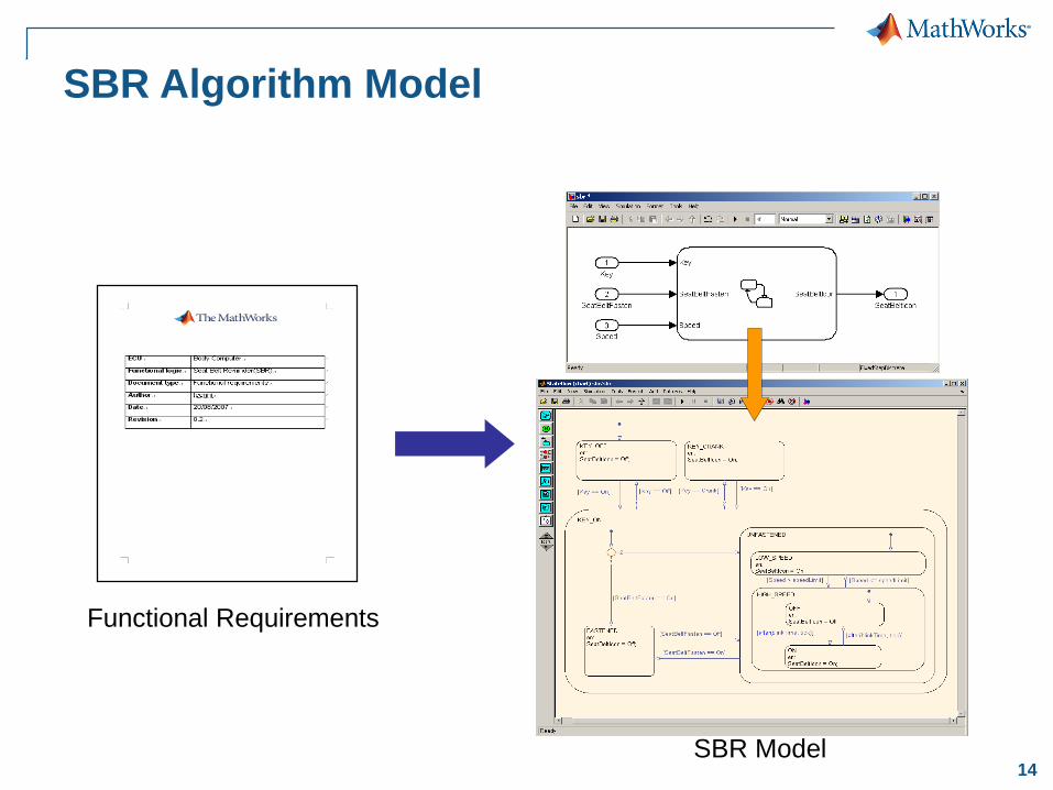
SBR Algorithm Model
Functional Requirements
SBR Model
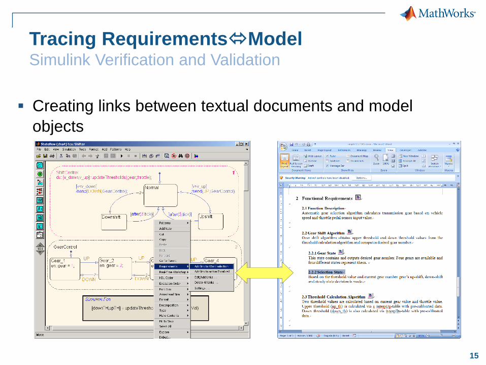
15
Creating links between textual documents and model
objects
Tracing RequirementsModelSimulink Verification and Validation
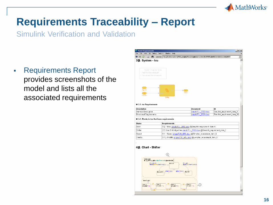
16
Requirements Traceability – ReportSimulink Verification and Validation
Requirements Report
provides screenshots of the
model and lists all the
associated requirements
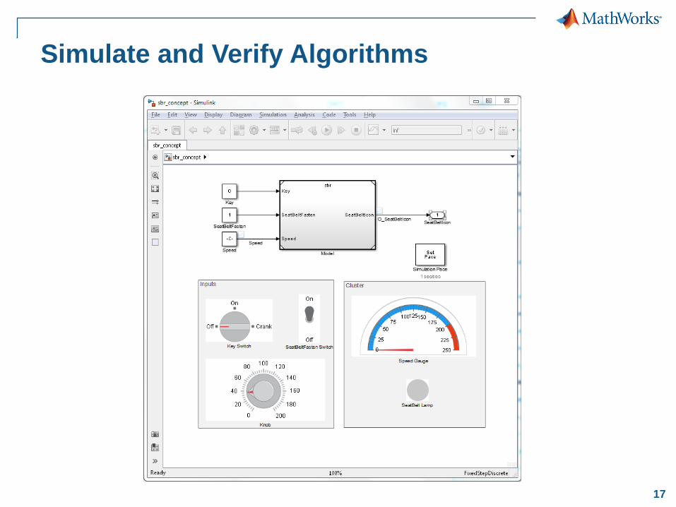
17
Simulate and Verify Algorithms
18
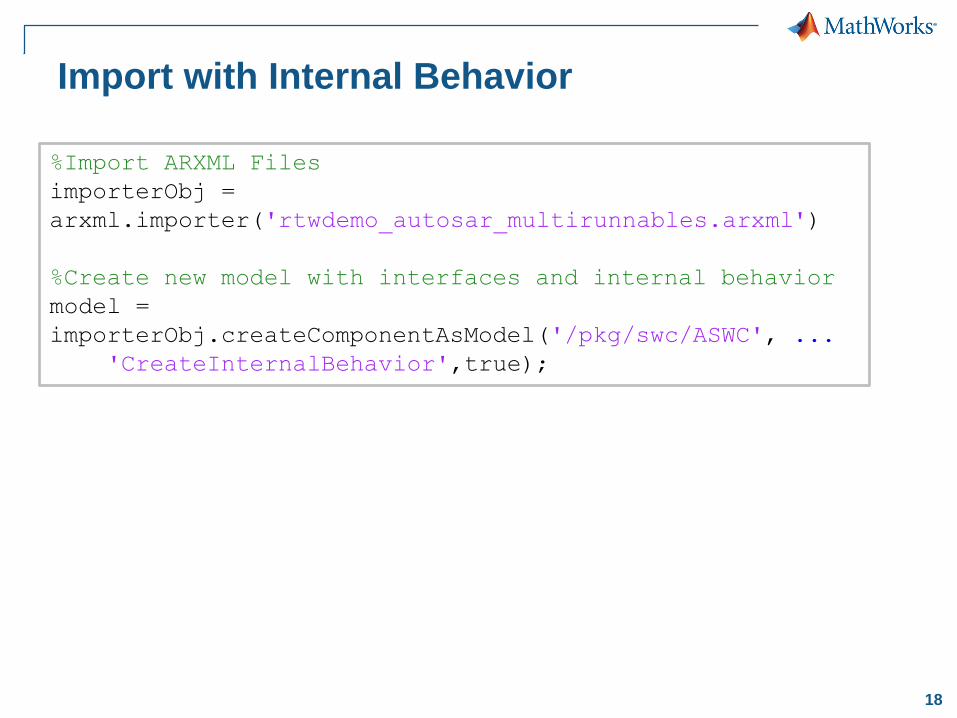
Import with Internal Behavior
%Import ARXML Files
importerObj =
arxml.importer('rtwdemo_autosar_multirunnables.arxml')
%Create new model with interfaces and internal behavior
model =
importerObj.createComponentAsModel('/pkg/swc/ASWC', ...
'CreateInternalBehavior',true);
19
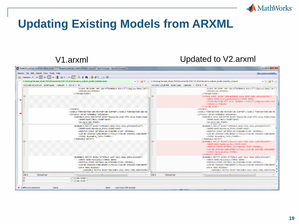
Updating Existing Models from ARXML
Updated to V2.arxmlV1.arxml
20
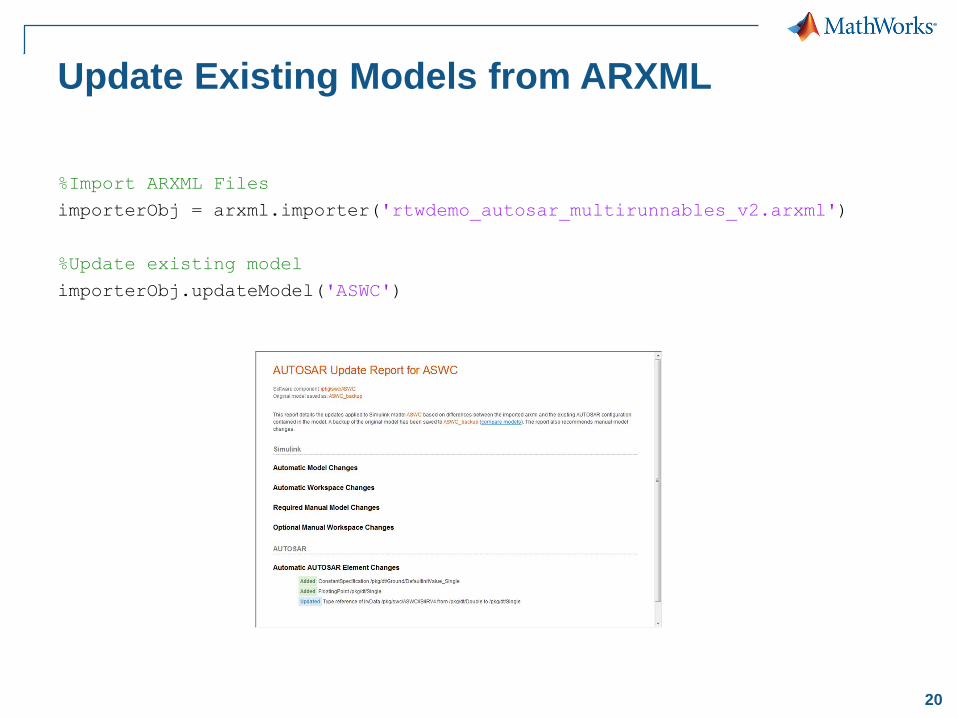
Update Existing Models from ARXML
%Import ARXML Files
importerObj = arxml.importer('rtwdemo_autosar_multirunnables_v2.arxml')
%Update existing model
importerObj.updateModel('ASWC')
21
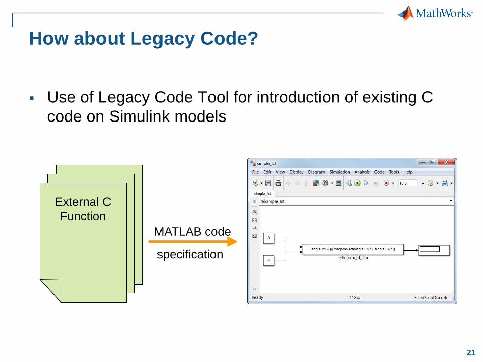
How about Legacy Code?
Use of Legacy Code Tool for introduction of existing C
code on Simulink models
specification
External C
Function
MATLAB code

22© 2015 The MathWorks, Inc.
Starting from SimulinkBottom-up Approach
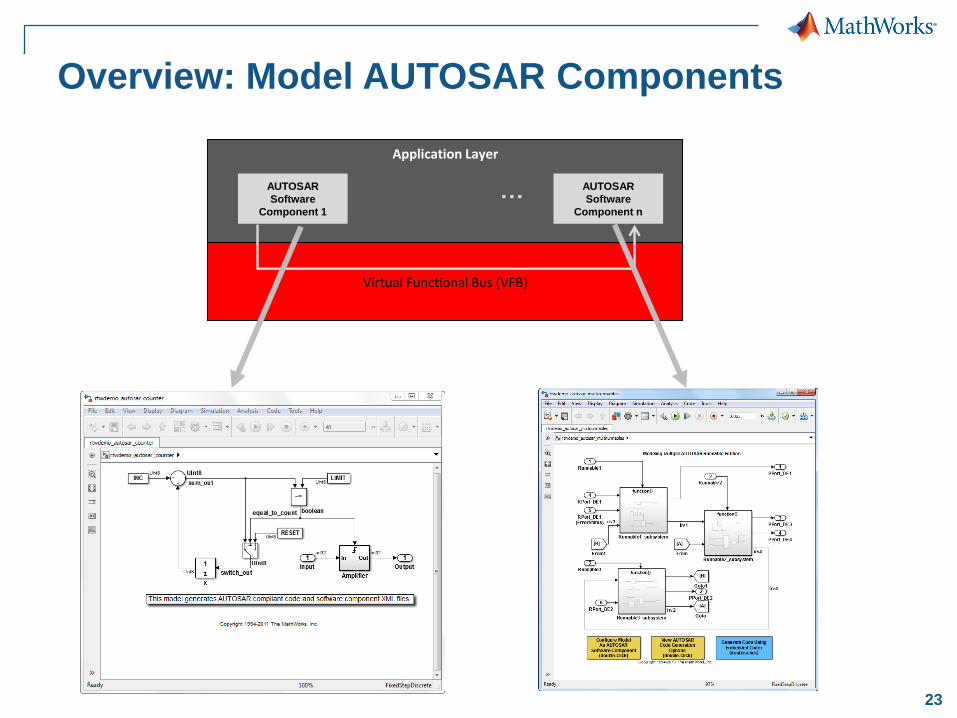
23
Application Layer
Virtual Functional Bus (VFB)
…AUTOSAR
Software
Component 1
AUTOSAR
Software
Component n
Overview: Model AUTOSAR Components
24
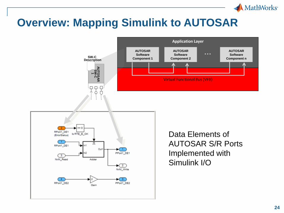
Overview: Mapping Simulink to AUTOSAR
Application Layer
Virtual Functional Bus (VFB)
…AUTOSAR
Software
Component 1
AUTOSAR
Software
Component 2
AUTOSAR
Software
Component n
AU
TO
SA
RS
W-C
1
SW-CDescription
Data Elements of
AUTOSAR S/R Ports
Implemented with
Simulink I/O
25
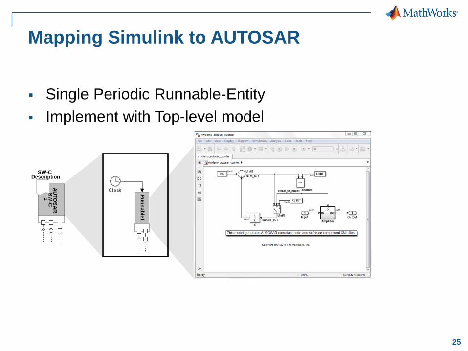
Mapping Simulink to AUTOSAR
Single Periodic Runnable-Entity
Implement with Top-level model
Ru
nn
ab
le1
AU
TO
SA
RS
W-C
1
SW-CDescription
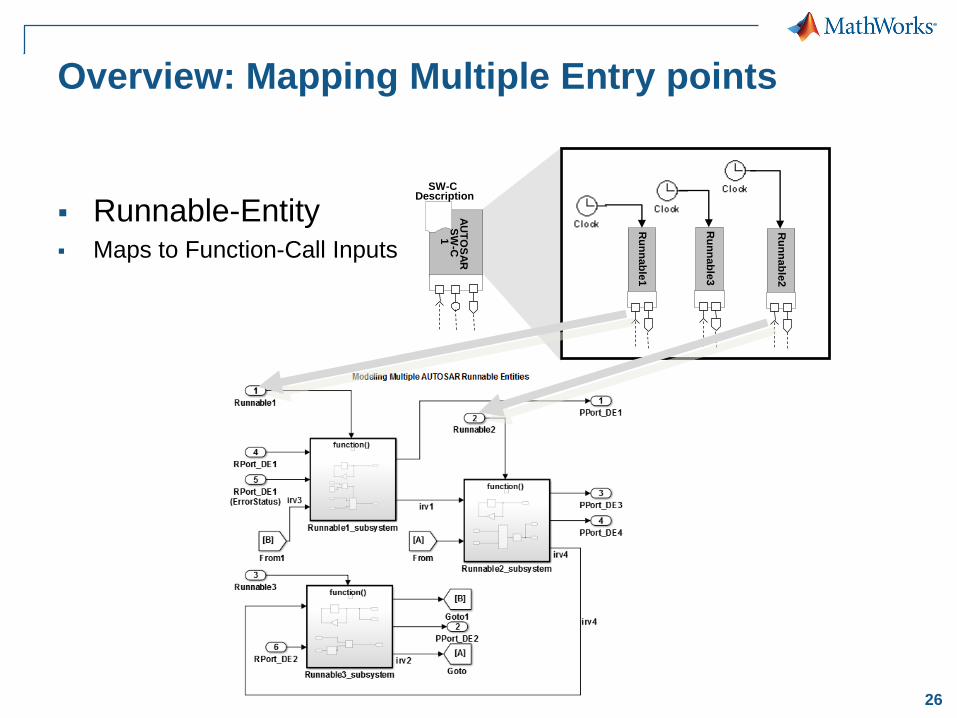
26
Ru
nn
ab
le1
Ru
nn
ab
le2
AU
TO
SA
RS
W-C
1
SW-CDescription
Ru
nn
ab
le3
Overview: Mapping Multiple Entry points
Runnable-Entity Maps to Function-Call Inputs
27
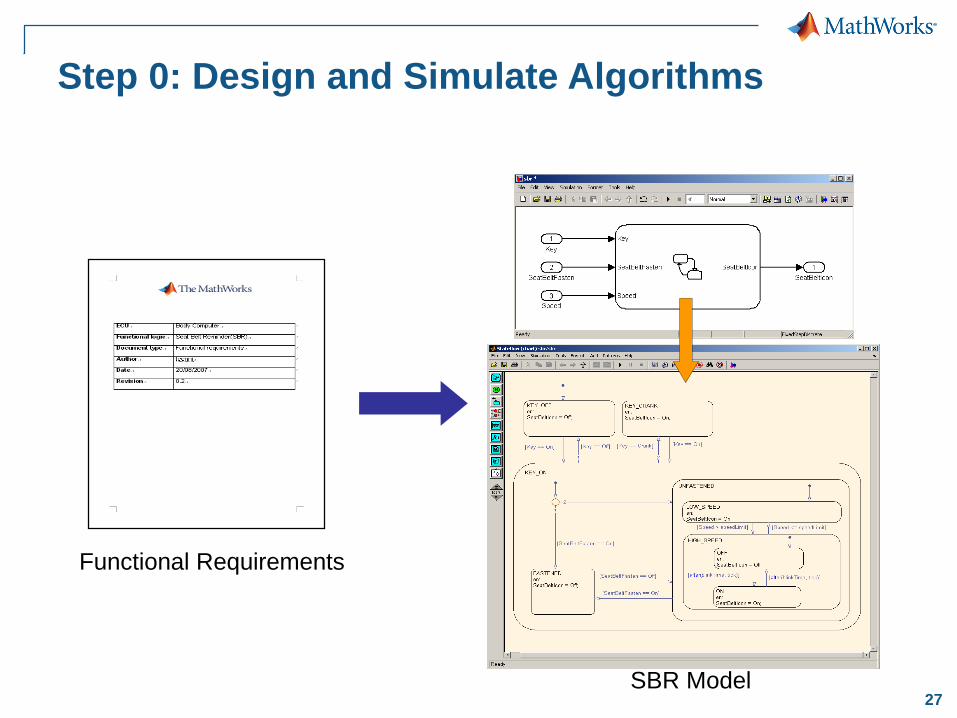
Step 0: Design and Simulate Algorithms
Functional Requirements
SBR Model
28
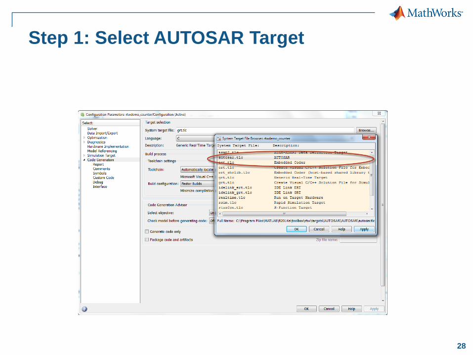
Step 1: Select AUTOSAR Target
29
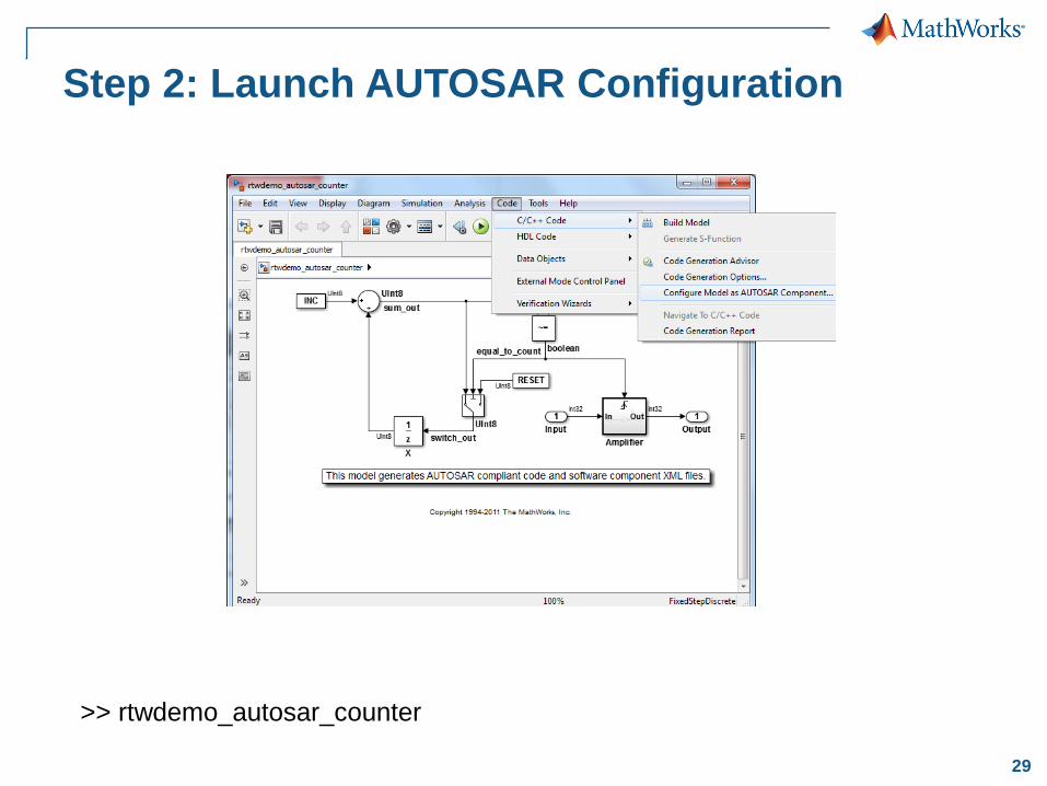
Step 2: Launch AUTOSAR Configuration
>> rtwdemo_autosar_counter
30
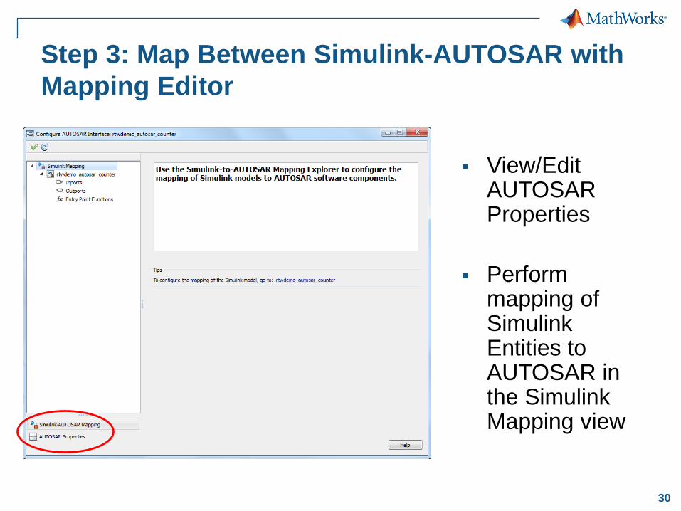
Step 3: Map Between Simulink-AUTOSAR with
Mapping Editor
View/Edit AUTOSAR Properties
Perform mapping of Simulink Entities to AUTOSAR in the Simulink Mapping view
31
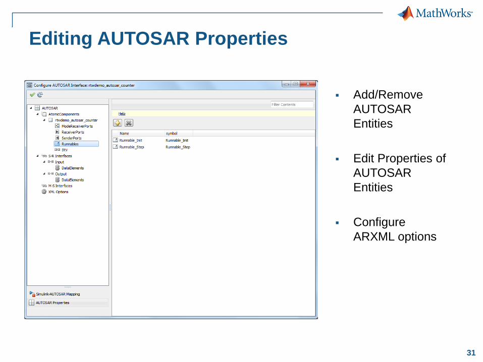
Editing AUTOSAR Properties
Add/Remove
AUTOSAR
Entities
Edit Properties of
AUTOSAR
Entities
Configure
ARXML options
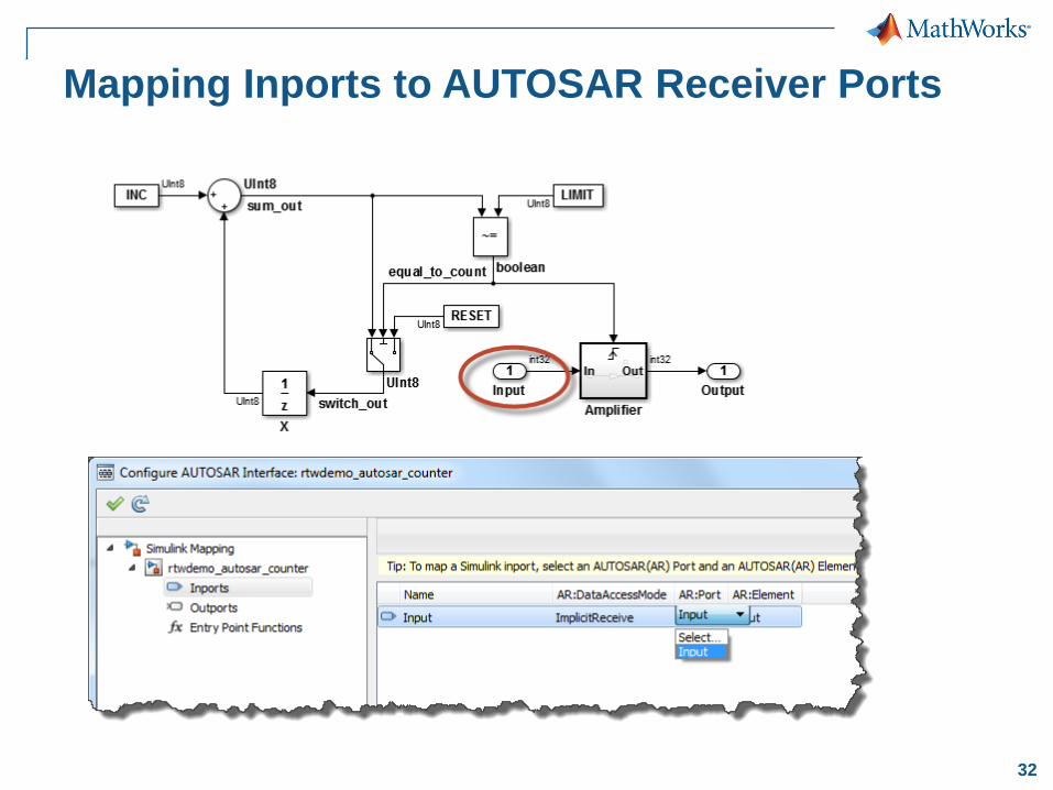
32
Mapping Inports to AUTOSAR Receiver Ports
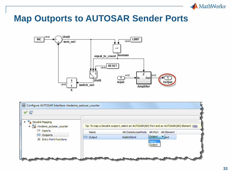
33
Map Outports to AUTOSAR Sender Ports
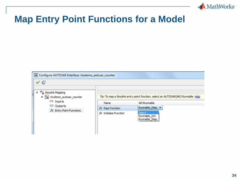
34
Map Entry Point Functions for a Model
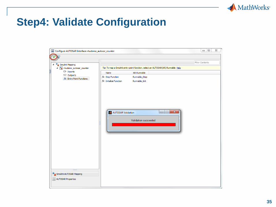
35
Step4: Validate Configuration
36
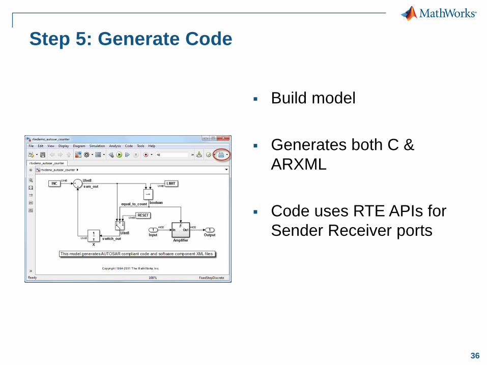
Step 5: Generate Code
Build model
Generates both C &
ARXML
Code uses RTE APIs for
Sender Receiver ports
37
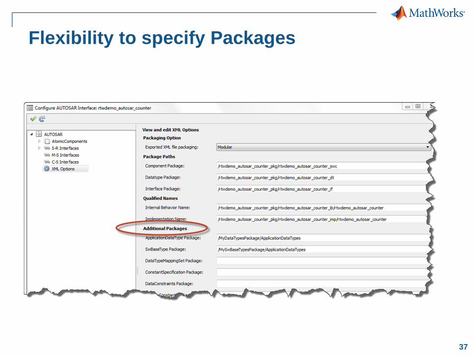
Flexibility to specify Packages
50© 2015 The MathWorks, Inc.
Verification of AUTOSAR ASWC with
Model
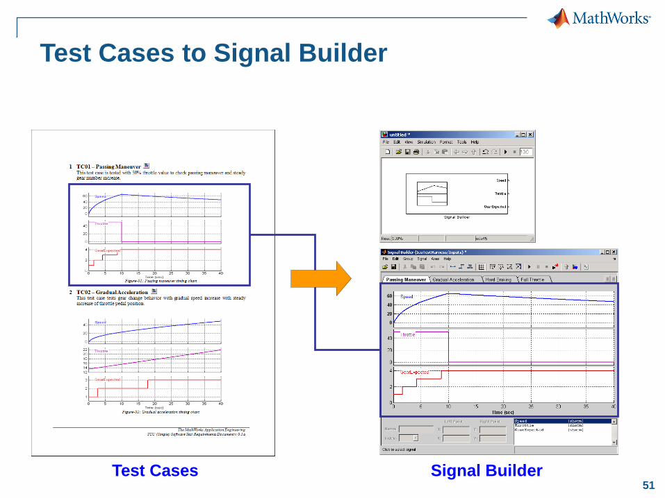
51Test Cases Signal Builder
Test Cases to Signal Builder
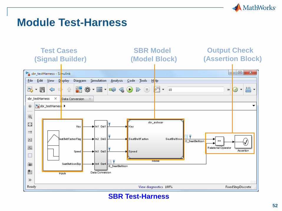
52
Module Test-Harness
SBR Test-Harness
Test Cases
(Signal Builder)
SBR Model
(Model Block)
Output Check
(Assertion Block)
53
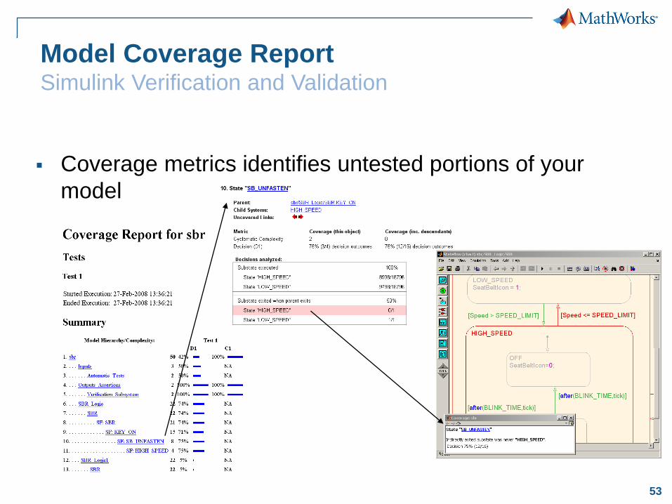
Model Coverage ReportSimulink Verification and Validation
Coverage metrics identifies untested portions of your
model
54
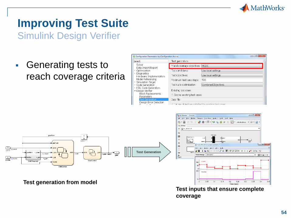
Improving Test SuiteSimulink Design Verifier
Generating tests to
reach coverage criteria
Test generation from model
Test inputs that ensure complete
coverage
Test Generation
55
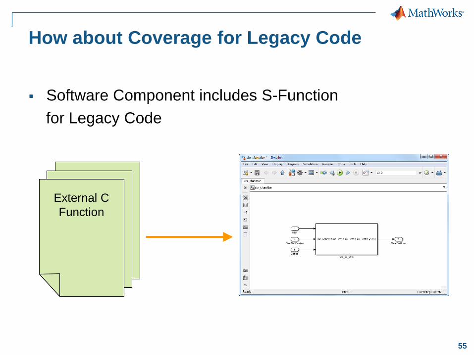
How about Coverage for Legacy Code
Software Component includes S-Function
for Legacy Code
External C
Function
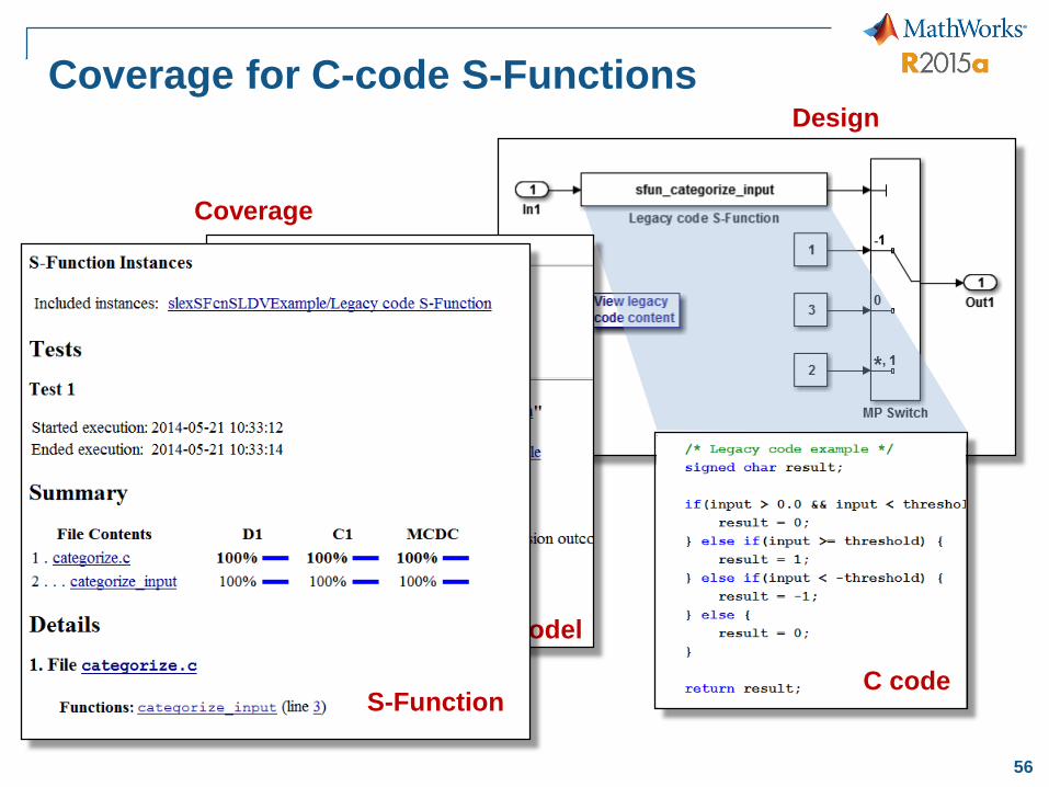
56
Coverage for C-code S-Functions
C code
Coverage
Model
Design
S-Function
57© 2015 The MathWorks, Inc.
Verification of AUTOSAR ASWC for
Generated Code
58
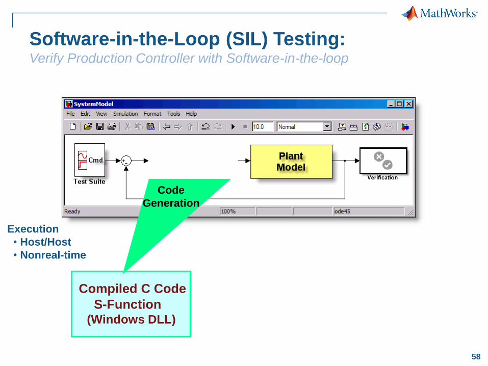
Compiled C Code
S-Function(Windows DLL)
Code
Generation
Execution
• Host/Host
• Nonreal-time
Software-in-the-Loop (SIL) Testing:Verify Production Controller with Software-in-the-loop
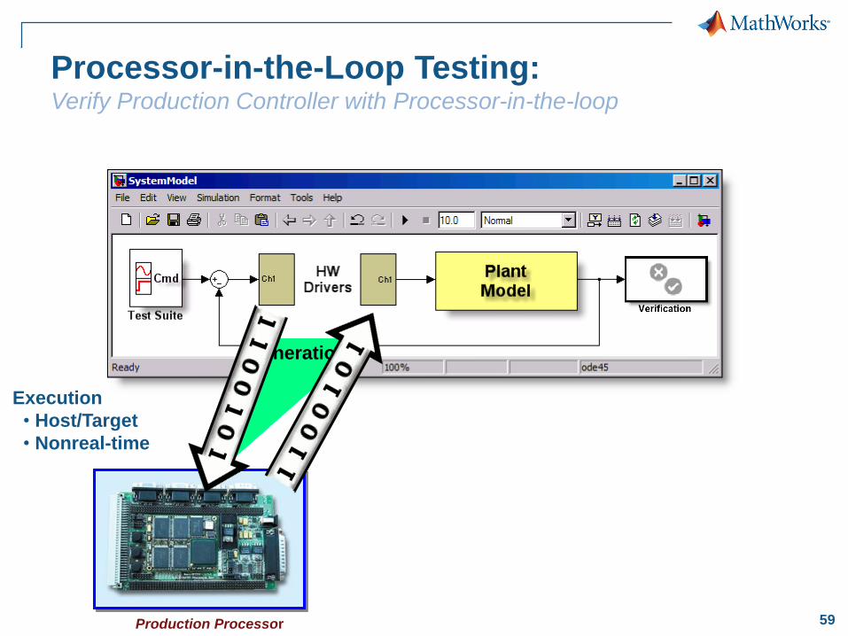
59Production Processor
Code
Generation
Execution
• Host/Target
• Nonreal-time
Processor-in-the-Loop Testing:Verify Production Controller with Processor-in-the-loop
60
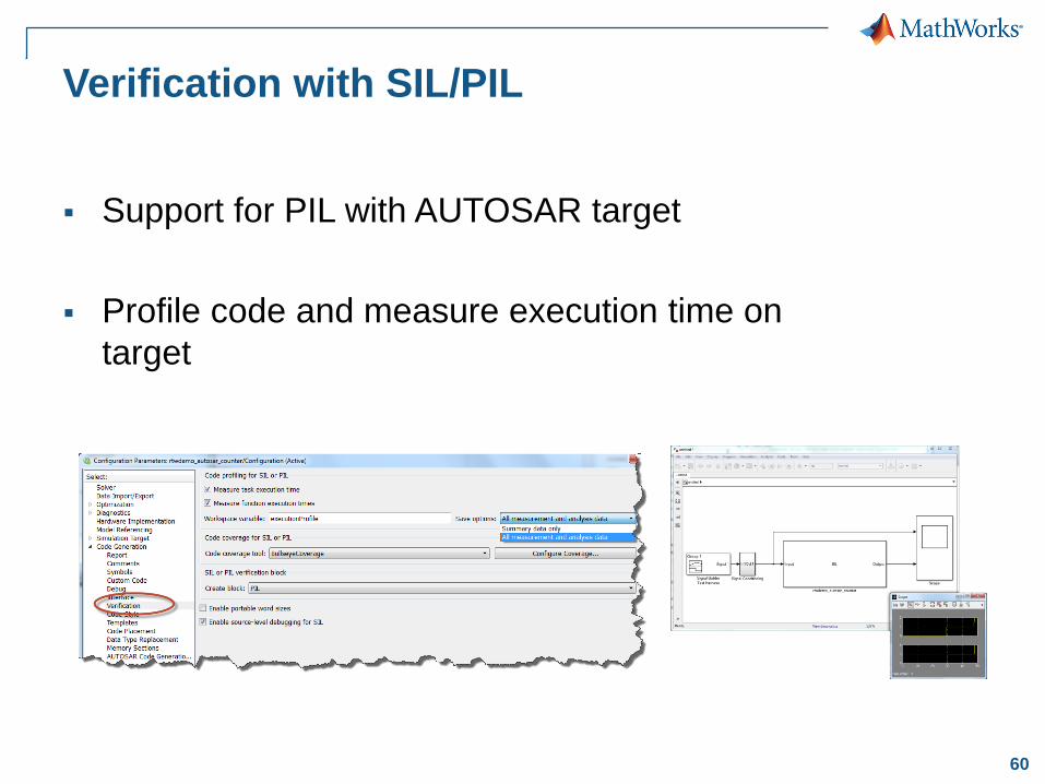
Verification with SIL/PIL
Support for PIL with AUTOSAR target
Profile code and measure execution time on
target
61© 2015 The MathWorks, Inc.
Formal Verification of Generated Code
with Polyspace
Can you prove absence of run-time errors?
62
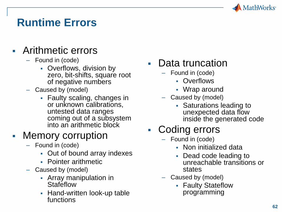
Arithmetic errors– Found in (code)
Overflows, division by zero, bit-shifts, square root of negative numbers
– Caused by (model)
Faulty scaling, changes in or unknown calibrations, untested data ranges coming out of a subsystem into an arithmetic block
Memory corruption– Found in (code)
Out of bound array indexes
Pointer arithmetic– Caused by (model)
Array manipulation in Stafeflow
Hand-written look-up table functions
Data truncation– Found in (code)
Overflows
Wrap around– Caused by (model)
Saturations leading to unexpected data flow inside the generated code
Coding errors– Found in (code)
Non initialized data
Dead code leading to unreachable transitions or states
– Caused by (model)
Faulty Stateflow programming
Runtime Errors
64
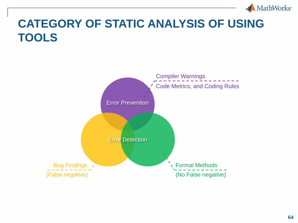
CATEGORY OF STATIC ANALYSIS OF USING
TOOLS
Compiler Warnings
Bug Findings Formal Methods
Code Metrics, and Coding Rules
(No False negative)(False negative)
Error Prevention
Error Detection
65
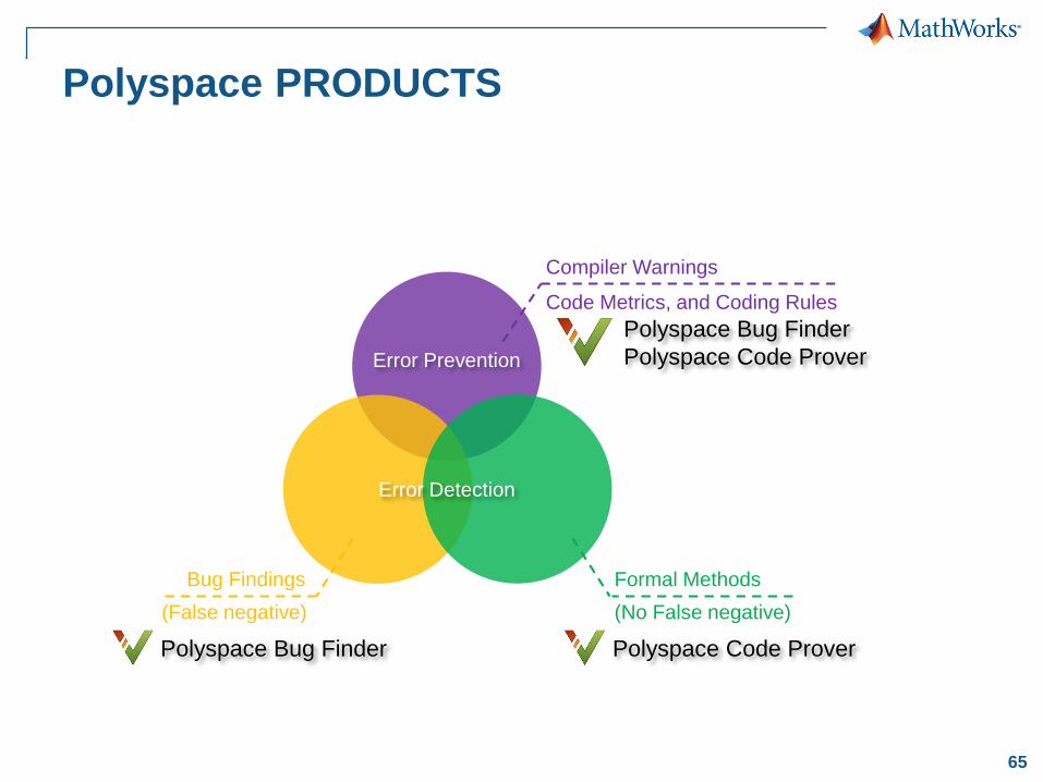
Polyspace PRODUCTS
Compiler Warnings
Bug Findings Formal Methods
Code Metrics, and Coding Rules
(No False negative)(False negative)
Polyspace Bug Finder
Polyspace Code Prover
Polyspace Bug Finder Polyspace Code Prover
Error Prevention
Error Detection
66
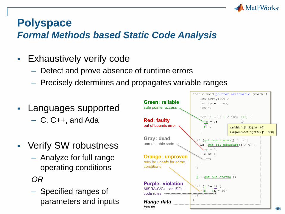
PolyspaceFormal Methods based Static Code Analysis
Exhaustively verify code
– Detect and prove absence of runtime errors
– Precisely determines and propagates variable ranges
Languages supported
– C, C++, and Ada
Verify SW robustness
– Analyze for full range
operating conditions
OR
– Specified ranges of
parameters and inputs
67
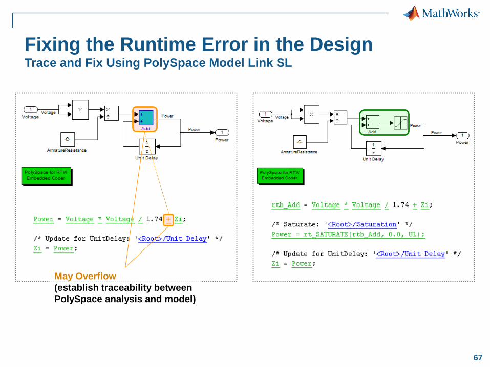
Fixing the Runtime Error in the DesignTrace and Fix Using PolySpace Model Link SL
May Overflow
(establish traceability between
PolySpace analysis and model)

68© 2015 The MathWorks, Inc.
Formal Verification in Design phase
with Simulink Design Verifier
Is it possible to verify early in “Design”
phase?
Can you prove your design always satisfies
requirements?
69
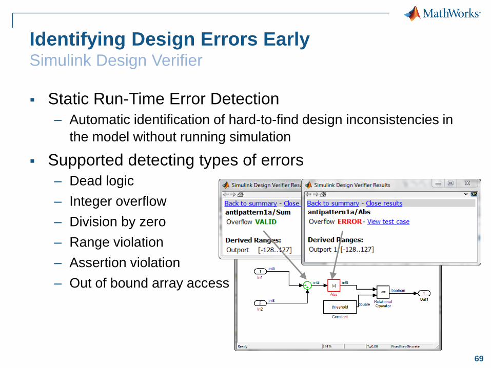
Identifying Design Errors EarlySimulink Design Verifier
Static Run-Time Error Detection
– Automatic identification of hard-to-find design inconsistencies in
the model without running simulation
Supported detecting types of errors
– Dead logic
– Integer overflow
– Division by zero
– Range violation
– Assertion violation
– Out of bound array access
70
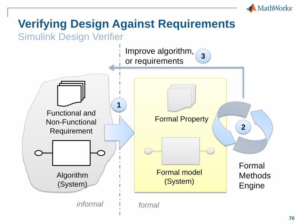
Verifying Design Against RequirementsSimulink Design Verifier
Algorithm
(System)
Functional and
Non-Functional
Requirement
informal formal
1
Formal model
(System)
Formal Property2
3Improve algorithm,
or requirements
Formal
Methods
Engine
71
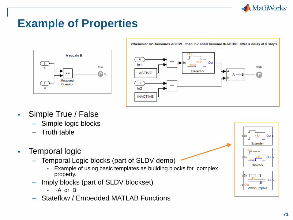
Example of Properties
Simple True / False– Simple logic blocks
– Truth table
Temporal logic– Temporal Logic blocks (part of SLDV demo)
Example of using basic templates as building blocks for complex property.
– Imply blocks (part of SLDV blockset) ~A or B
– Stateflow / Embedded MATLAB Functions
72
Summary
Simulink and Embedded Coder provide extensive
AUTOSAR capabilities out-of-the-box.
Use one AUTOSAR workflow (Top-Down/Bottom-Up)
that best support your workflow and AUTOSAR
concepts
Take advantage of Production Code Generation to
accelerate your AUTOSAR projects while reducing risk
and improving quality.
Various Model-Based Verification methods can also be
applied to AUTOSAR ASWC development.

73
Change the world by
Accelerating the paceof discovery, innovation, development, and learning
in engineering and science